


 Loading...

SDLT 220 and SDLT 320 Product Manual
Copyright
Copyright © 2004 by Quantum Corporation. All rights reserved.
Document Origination: Boulder, Colorado, USA.
Trademarks
Quantum, the Quantum logo, and the DLTtape logo are trademarks of Quantum Corporation registered in the U.S.A. and other countries. DLTtape, DLTSage, Value DLTtape, and Super DLTtape are trademarks of Quantum Corporation.
Other company and product names used in this document are trademarks, registered trademarks, or service marks of their respective owners.
Legal Disclaimers
The information contained in this document is the exclusive property of Quantum Corporation. Quantum retains its copyright on the information contained herein in all cases and situations of usage, including derivative works. The possessor agrees to safeguard this information and to maintain it in confidence and not re-publish it in whole or in part without Quantum’s prior written consent.
Quantum reserves the right to make changes and improvements to its products, without incurring any obligation to incorporate such changes or improvements in units previously sold or shipped.
It is the responsibility of the user to carefully read and understand the User Manual statements for Class A Equipment and Class B Equipment that appear on page iv and page v, respectively.
Contact Information
You can request Quantum publications from your Quantum Sales Representative or order them directly from Quantum.
Telephone numbers and street addresses change frequently; for the latest, up-to-date contact information, visit:
www.quantum.com
Telephone numbers, street addresses, time zones, and other pertinent facts are listed in the Support section of the web site.
ii |
March 2004 |
81-85002-01 |

SDLT 220 and SDLT 320 Product Manual
Revision History
Revisions made to this document are listed below in chronological order.
Document Release |
Date |
Summary of Changes |
|
|
|
A |
March 14, 2002 |
Create document. |
|
|
|
A01 |
April 29, 2002 |
Initial release. Note: This manual supersedes |
|
|
Quantum document 81-80000-01. |
|
|
|
A02 |
April 30, 2002 |
Minor changes. |
|
|
|
A03 |
October 30, 2002 |
Scheduled update. |
|
|
|
A04 |
March 12, 2004 |
Maintenance update. Added information about tape |
|
|
density selection. Updated Appendices A and B. |
|
|
|
81-85002-01 |
March 2004 |
iii |

SDLT 220 and SDLT 320 Product Manual
User Manual Statements for Class A Equipment (Internal Tape System)
This equipment generates, uses, and may emit radio frequency energy. The equipment has been tested and found to comply with the limits for a Class A digital device, pursuant to Part 15 of the FCC rules. These limits are designed to provide reasonable protection against radio frequency interference in a commercial installation.
Operation of this equipment in a residential area may cause interference, in which case the user at his own expense will be required to take whatever measures may be required to correct the interference.
Any modifications to this device—unless expressly approved by the manufacturer—can void the user’s authority to operate this equipment under Part 15 of the FCC rules.
Note: Additional information on the need to interconnect the device with shielded (data) cables or the need for special devices, such as ferrite beads on cables, is required if such means of interference suppression was used in the qualification test for the device. This information will vary from device to device and needs to be obtained from the EMC (Electromagnetic Compatibility) group or product manager.
Warning!
This is a Class A product. In a domestic environment this product may cause radio interference in which case the user may be required to take adequate measures.
Achtung!
Dieses ist ein Gerät der Funkstörgrenzwertklasse A. In Wohnbereichen können bei Betrieb dieses Gerätes Rundfunkstörungen auftreten, in welchen Fällen der Benutzer für entsprechende Gegenmaßnahmen verantwortlich ist.
Warning!
This Class A digital apparatus complies with Canadian ICES-003.
Cet appareil numérique de la classe A est conforme à la norme NMB-003 du Canada.
Attention!
Ceci est un produit de Classe A. Dans un environnement domestique, ce produit risque de créer des interférences radioélectriques, il appartiendra alors à l'utilisateur de prendre les mesures spécifiques appropriées.
iv |
March 2004 |
81-85002-01 |

SDLT 220 and SDLT 320 Product Manual
User Manual Statements for Class B Equipment (Tabletop Tape System)
This equipment has been tested and found to comply with the limits for a Class B digital device, pursuant to Part 15 of the FCC rules. These limits are designed to provide reasonable protection against harmful interference in a residential installation. Operation is subject to the following two conditions: (1) This device may not cause harmful interference, and (2) this device must accept any interference that may cause undesirable operation.
Any modifications to this device—unless expressly approved by the manufacturer—can void the user’s authority to operate this equipment under Part 15 of the FCC rules.
This equipment generates, uses, and can radiate radio frequency energy and, if not installed and used in accordance with the instructions, may cause harmful interference to radio communications. However, there is no guarantee that interference will not occur in a particular installation. If this equipment does cause harmful interference to radio or television reception, which can be determined by turning the equipment off and on, the user is encouraged to try to correct the interference by one or more of the following measures:
•Reorient or relocate the receiving antenna.
•Increase the separation between the equipment and receiver.
•Connect the equipment into an outlet on a circuit different from that to which the receiver is connected.
•Consult the dealer or an experienced radio or TV technician for help.
Note: Additional information on the need to interconnect the device with shielded (data) cables or the need for special devices, such as ferrite beads on cables, is required if such means of interference suppression was used in the qualification test for the device. This information will vary
81-85002-01 |
March 2004 |
v |

SDLT 220 and SDLT 320 Product Manual
from device to device and needs to be obtained from the EMC (Electromagnetic Compatibility) group or product manager.
This Class B digital apparatus complies with Canadian ICES-003.
Cet appareil numérique de la classe B est conforme à la norme NMB-003 du Canada.
|
|
|
|
|
|
|
|
|
|
|
|
|
|
|
|
|
|
|
|
|
|
|
|
vi |
March 2004 |
81-85002-01 |
|||

Table of Contents
CHAPTER 1 Introduction. . . . . . . . . . . . . . . . . . . . . . . . . . . . . . |
1-1 |
Purpose and Scope. . . . . . . . . . . . . . . . . . . . . . . . . . . . . . . . . . . . . . . . . . 1-1 Referenced Documents . . . . . . . . . . . . . . . . . . . . . . . . . . . . . . . . . . . . . . 1-1 Related Documents . . . . . . . . . . . . . . . . . . . . . . . . . . . . . . . . . . . . . . . . . 1-2 Structure of this Manual . . . . . . . . . . . . . . . . . . . . . . . . . . . . . . . . . . . . . 1-2 Conventions . . . . . . . . . . . . . . . . . . . . . . . . . . . . . . . . . . . . . . . . . . . . . . . 1-3 For More Information . . . . . . . . . . . . . . . . . . . . . . . . . . . . . . . . . . . . . . . 1-3 Reader Comments . . . . . . . . . . . . . . . . . . . . . . . . . . . . . . . . . . . . . . . . . . 1-4
CHAPTER 2 SDLT 220/320 Product Information . . . . . . . . . . . 2-1
Overview . . . . . . . . . . . . . . . . . . . . . . . . . . . . . . . . . . . . . . . . . . . . . . . . . 2-1
SDLT 220/320 Product Features . . . . . . . . . . . . . . . . . . . . . . . . . . . . . . . 2-2
SDLT 220/320 Technology . . . . . . . . . . . . . . . . . . . . . . . . . . . . . . . . . . . 2-3
Laser Guided Magnetic Recording . . . . . . . . . . . . . . . . . . . . . . . . . . 2-3
Pivoting Optical Servo . . . . . . . . . . . . . . . . . . . . . . . . . . . . . . . . . . . . 2-4
Magneto Resistive Cluster Heads . . . . . . . . . . . . . . . . . . . . . . . . . . . 2-4
Advanced Partial Response Maximum Likelihood . . . . . . . . . . . . . . 2-5
Advanced Metal Powder Media . . . . . . . . . . . . . . . . . . . . . . . . . . . . . 2-5
Positive Engagement . . . . . . . . . . . . . . . . . . . . . . . . . . . . . . . . . . . . . 2-5
SDLT 220/320 Modular Design . . . . . . . . . . . . . . . . . . . . . . . . . . . . . . . 2-6
Data Control Module . . . . . . . . . . . . . . . . . . . . . . . . . . . . . . . . . . . . . 2-7
Tape Control Module . . . . . . . . . . . . . . . . . . . . . . . . . . . . . . . . . . . . . 2-8
TCM PCBA . . . . . . . . . . . . . . . . . . . . . . . . . . . . . . . . . . . . . . . . . 2-8
Base Plate . . . . . . . . . . . . . . . . . . . . . . . . . . . . . . . . . . . . . . . . . . . 2-8
Cartridge Receiver . . . . . . . . . . . . . . . . . . . . . . . . . . . . . . . . . . . . 2-8
Positive Engagement Tape Leader Buckling Mechanism . . . . . . 2-9
Front Panel Module . . . . . . . . . . . . . . . . . . . . . . . . . . . . . . . . . . . . . . 2-9
Electronic Interface Module. . . . . . . . . . . . . . . . . . . . . . . . . . . . . . . 2-10
81-85002-01 |
March 2004 |
vii |

Table of Contents |
SDLT 220 and SDLT 320 Product Manual |
|
|
Super DLTtape I Data Cartridge Module . . . . . . . . . . . . . . . . . . . . . 2-10 Key Differences Between the SDLT 220 and the SDLT 320 . . . . . . . . 2-11 Quantum Diagnostics Tools . . . . . . . . . . . . . . . . . . . . . . . . . . . . . . . . . 2-12 TapeAlert . . . . . . . . . . . . . . . . . . . . . . . . . . . . . . . . . . . . . . . . . . . . . . . . 2-13
CHAPTER 3 Drive Specifications . . . . . . . . . . . . . . . . . . . . . . . |
3-1 |
Product Specifications . . . . . . . . . . . . . . . . . . . . . . . . . . . . . . . . . . . . . . . 3-1
Interface Type . . . . . . . . . . . . . . . . . . . . . . . . . . . . . . . . . . . . . . . . . . 3-2
Physical Dimensions . . . . . . . . . . . . . . . . . . . . . . . . . . . . . . . . . . . . . 3-2
Storage Capacity . . . . . . . . . . . . . . . . . . . . . . . . . . . . . . . . . . . . . . . . 3-3
Compression. . . . . . . . . . . . . . . . . . . . . . . . . . . . . . . . . . . . . . . . . . . . 3-3
Data Integrity . . . . . . . . . . . . . . . . . . . . . . . . . . . . . . . . . . . . . . . . . . . 3-3
Maximum Data Transfer Rate . . . . . . . . . . . . . . . . . . . . . . . . . . . . . . 3-4
Head Life and MTBF . . . . . . . . . . . . . . . . . . . . . . . . . . . . . . . . . . . . . 3-4
Media Durability . . . . . . . . . . . . . . . . . . . . . . . . . . . . . . . . . . . . . . . . 3-5
Cartridge Life Expectancy . . . . . . . . . . . . . . . . . . . . . . . . . . . . . . . . . 3-5
Positive Engagement Tape Leader Buckling Mechanism . . . . . . . . . 3-6
Functional Specifications . . . . . . . . . . . . . . . . . . . . . . . . . . . . . . . . . . . . 3-6 SDLT 220/320 Performance Data . . . . . . . . . . . . . . . . . . . . . . . . . . . 3-7 Shock and Vibration Specifications . . . . . . . . . . . . . . . . . . . . . . . . . . 3-8 Current and Power Requirements . . . . . . . . . . . . . . . . . . . . . . . . . . 3-10 Tape System Recording Method . . . . . . . . . . . . . . . . . . . . . . . . . . . 3-12
Environmental Specifications . . . . . . . . . . . . . . . . . . . . . . . . . . . . . . . . 3-13
Air Flow Requirements . . . . . . . . . . . . . . . . . . . . . . . . . . . . . . . . . . 3-13
Temperature and Humidity . . . . . . . . . . . . . . . . . . . . . . . . . . . . . . . 3-14
Storage and Shipment. . . . . . . . . . . . . . . . . . . . . . . . . . . . . . . . . . . . 3-14
Altitude. . . . . . . . . . . . . . . . . . . . . . . . . . . . . . . . . . . . . . . . . . . . . . . 3-15
Particulate Contamination Limits . . . . . . . . . . . . . . . . . . . . . . . . . . 3-15
Recording Media Specifications . . . . . . . . . . . . . . . . . . . . . . . . . . . . . . 3-15
Backward-Read Compatibility Transfer Rates . . . . . . . . . . . . . . . . 3-17
viii |
March 2004 |
81-85002-01 |

SDLT 220 and SDLT 320 Product Manual Table of Contents
CHAPTER 4 Installing Your Tape Drive . . . . . . . . . . . . . . . . . . . |
4-1 |
Safety, Handling, and ESD Protection . . . . . . . . . . . . . . . . . . . . . . . . . . 4-2 Safety Precautions . . . . . . . . . . . . . . . . . . . . . . . . . . . . . . . . . . . . . . . 4-2 Handling . . . . . . . . . . . . . . . . . . . . . . . . . . . . . . . . . . . . . . . . . . . . . . . 4-3 Electrostatic Discharge Protection . . . . . . . . . . . . . . . . . . . . . . . . . . . 4-4 Pre-Installation Guidelines . . . . . . . . . . . . . . . . . . . . . . . . . . . . . . . . . . . 4-5 Configuring and Installing an Internal Tape Drive . . . . . . . . . . . . . . . . . 4-6 Setting the Internal Drive SCSI ID . . . . . . . . . . . . . . . . . . . . . . . . . . 4-7 Configuring the Internal Drive for TERMPWR . . . . . . . . . . . . . . . 4-11 Configuring the Internal Drive for Narrow SCSI . . . . . . . . . . . . . . 4-11 Installing the Internal Tape Drive. . . . . . . . . . . . . . . . . . . . . . . . . . . 4-11 Securing the Internal Tape Drive . . . . . . . . . . . . . . . . . . . . . . . . 4-12 Connecting the Internal Drive Cables. . . . . . . . . . . . . . . . . . . . . 4-13 Configuring and Installing a Tabletop Drive. . . . . . . . . . . . . . . . . . . . . 4-21 Configuring the Drive . . . . . . . . . . . . . . . . . . . . . . . . . . . . . . . . . . . 4-21 Installing the Tabletop Drive . . . . . . . . . . . . . . . . . . . . . . . . . . . . . . 4-22 SCSI Cables . . . . . . . . . . . . . . . . . . . . . . . . . . . . . . . . . . . . . . . . 4-22 AC Power Cable . . . . . . . . . . . . . . . . . . . . . . . . . . . . . . . . . . . . . 4-23
Confirming the Installation . . . . . . . . . . . . . . . . . . . . . . . . . . . . . . . . . . 4-24
CHAPTER 5 Using Your Tape Drive . . . . . . . . . . . . . . . . . . . . . |
5-1 |
Power On Self Test . . . . . . . . . . . . . . . . . . . . . . . . . . . . . . . . . . . . . . . . . 5-2 Performing a Trial Back-up . . . . . . . . . . . . . . . . . . . . . . . . . . . . . . . . . . . 5-3 Updating the Firmware . . . . . . . . . . . . . . . . . . . . . . . . . . . . . . . . . . . . . . 5-4 Update the Firmware Using the SCSI Bus. . . . . . . . . . . . . . . . . . . . . 5-4 Making a FUP/CUP Tape . . . . . . . . . . . . . . . . . . . . . . . . . . . . . . . . . 5-5 Using a CUP/FUP Tape . . . . . . . . . . . . . . . . . . . . . . . . . . . . . . . . . . . 5-5 Troubleshooting the Firmware (Code) Update . . . . . . . . . . . . . . . . . 5-6 Cleaning the Tape Mechanism . . . . . . . . . . . . . . . . . . . . . . . . . . . . . . . . 5-7 Occasional Cleaning of Tape Head . . . . . . . . . . . . . . . . . . . . . . . . . . 5-7 When to Use the Cleaning Tape. . . . . . . . . . . . . . . . . . . . . . . . . . . . . 5-8 Life Expectancy of the Cleaning Tape . . . . . . . . . . . . . . . . . . . . . . . . 5-8 Compatibility of the Cleaning Tape . . . . . . . . . . . . . . . . . . . . . . . . . . 5-8 Loading the Cleaning Tape Into a Tabletop Drive . . . . . . . . . . . . . . . 5-9 Front Panel Controls and LEDs. . . . . . . . . . . . . . . . . . . . . . . . . . . . . . . 5-10 Density Selection. . . . . . . . . . . . . . . . . . . . . . . . . . . . . . . . . . . . . . . . . . 5-13 Selecting Tape Density. . . . . . . . . . . . . . . . . . . . . . . . . . . . . . . . . . . 5-13 Selecting Density via the Host over the SCSI Bus . . . . . . . . . . . 5-13 SDLT 220 and SDLT 320 Compatibility Issues. . . . . . . . . . . . . 5-14
81-85002-01 |
March 2004 |
ix |

Table of Contents |
SDLT 220 and SDLT 320 Product Manual |
|
|
Forcing Tape Density with MODE SELECT Parameters . . . . . 5-14 Tape Density and the Drive Density Indicator. . . . . . . . . . . . . . . . . 5-15 Troubleshooting. . . . . . . . . . . . . . . . . . . . . . . . . . . . . . . . . . . . . . . . . . . 5-17 POST Troubleshooting. . . . . . . . . . . . . . . . . . . . . . . . . . . . . . . . . . . 5-17 Over Temperature Condition . . . . . . . . . . . . . . . . . . . . . . . . . . . . . . 5-19
CHAPTER 6 SCSI Description . . . . . . . . . . . . . . . . . . . . . . . . . |
6-1 |
SCSI Overview . . . . . . . . . . . . . . . . . . . . . . . . . . . . . . . . . . . . . . . . . . . . 6-1
SCSI-2 Commands . . . . . . . . . . . . . . . . . . . . . . . . . . . . . . . . . . . . . . . . . 6-3
SCSI-3 Commands . . . . . . . . . . . . . . . . . . . . . . . . . . . . . . . . . . . . . . . . . 6-5
Parity . . . . . . . . . . . . . . . . . . . . . . . . . . . . . . . . . . . . . . . . . . . . . . . . . . . . 6-6
Signal States . . . . . . . . . . . . . . . . . . . . . . . . . . . . . . . . . . . . . . . . . . . . . . 6-6
Signal Values . . . . . . . . . . . . . . . . . . . . . . . . . . . . . . . . . . . . . . . . . . . 6-6
SCSI IDs. . . . . . . . . . . . . . . . . . . . . . . . . . . . . . . . . . . . . . . . . . . . . . . 6-8
SCSI Signals . . . . . . . . . . . . . . . . . . . . . . . . . . . . . . . . . . . . . . . . . . . . . . 6-8
SCSI Signal Definitions . . . . . . . . . . . . . . . . . . . . . . . . . . . . . . . . . . . 6-9
Signal Bus Timing . . . . . . . . . . . . . . . . . . . . . . . . . . . . . . . . . . . . . . 6-10
CHAPTER 7 Regulatory Compliance . . . . . . . . . . . . . . . . . . . . |
7-1 |
Safety Regulations. . . . . . . . . . . . . . . . . . . . . . . . . . . . . . . . . . . . . . . . . . 7-1
Safety Certifications. . . . . . . . . . . . . . . . . . . . . . . . . . . . . . . . . . . . . . 7-1
Safety Requirements . . . . . . . . . . . . . . . . . . . . . . . . . . . . . . . . . . . . . 7-2
Electromagnetic Field Specifications . . . . . . . . . . . . . . . . . . . . . . . . . . . 7-2
Electromagnetic Emissions . . . . . . . . . . . . . . . . . . . . . . . . . . . . . . . . 7-2
Electromagnetic Interference Susceptibility . . . . . . . . . . . . . . . . . . . 7-3
Conducted Emissions . . . . . . . . . . . . . . . . . . . . . . . . . . . . . . . . . . . . . 7-3
Radiated Emissions . . . . . . . . . . . . . . . . . . . . . . . . . . . . . . . . . . . . . . 7-4
Susceptibility and ESD Limits . . . . . . . . . . . . . . . . . . . . . . . . . . . . . . 7-5
Acoustic Noise Emissions . . . . . . . . . . . . . . . . . . . . . . . . . . . . . . . . . . . . 7-6
x |
March 2004 |
81-85002-01 |
SDLT 220 and SDLT 320 Product Manual |
Table of Contents |
|
|
APPENDIX A Super DLTtape I Data Cartridge . . . . . . . . . . . . . . A-1
Recognizing Quantum-authorized Super DLTtape Data Cartridges . . . . A-2
Data Cartridge Handling Guidelines . . . . . . . . . . . . . . . . . . . . . . . . . . . . A-3
Data Cartridge Inspection Procedure . . . . . . . . . . . . . . . . . . . . . . . . . . . A-4
Data Cartridge Write-protect Switch . . . . . . . . . . . . . . . . . . . . . . . . . . . . A-7
Loading a Data Cartridge . . . . . . . . . . . . . . . . . . . . . . . . . . . . . . . . . . . A-10
Unloading a Data Cartridge. . . . . . . . . . . . . . . . . . . . . . . . . . . . . . . . . . A-11
Overwriting 320-Formatted Super DLTtape I Data Cartridges. . . . . . . A-11
APPENDIX B DLTtape IV Data Cartridge . . . . . . . . . . . . . . . . . . B-1
Data Cartridge Handling Guidelines . . . . . . . . . . . . . . . . . . . . . . . . . . . . B-2
Data Cartridge Inspection Procedure . . . . . . . . . . . . . . . . . . . . . . . . . . . B-3
Data Cartridge Write-protect Switch . . . . . . . . . . . . . . . . . . . . . . . . . . . . B-7
Loading a Data Cartridge . . . . . . . . . . . . . . . . . . . . . . . . . . . . . . . . . . . . B-8
Unloading a Data Cartridge. . . . . . . . . . . . . . . . . . . . . . . . . . . . . . . . . . . B-9
Glossary G-1
81-85002-01 |
March 2004 |
xi |

Table of Contents |
SDLT 220 and SDLT 320 Product Manual |
|
|
xii |
March 2004 |
81-85002-01 |

List of Tables
CHAPTER 1 |
Introduction. . . . . . . . . . . . . . . . . . . . . . . . . . . . . . |
1-1 |
Table 1-1. Typographical Conventions . . . . . . . . . . . . . . . . . . . . . . . . . . . . . . . . . . . . . . . . . . . . . . . |
. . 1-3 |
|
CHAPTER 2 |
SDLT 220/320 Product Information . . . . . . . . . . . |
2-1 |
Table 2-1. A Comparison of SDLT 220 and SDLT 320 Features . . . . . . . . . . . . . . . . . . . . . . . . . . . |
. 2-11 |
|
CHAPTER 3 |
Drive Specifications . . . . . . . . . . . . . . . . . . . . . . . |
3-1 |
Table 3-1. SDLT 220/320 Physical Dimensions and Shipping Weight . . . . . . . . . . . . . . . . . . . . . . . . . 3-2 Table 3-2. SDLT 220/320 Storage Capacity . . . . . . . . . . . . . . . . . . . . . . . . . . . . . . . . . . . . . . . . . . . . . 3-3 Table 3-3. Data Transfer Error Rates. . . . . . . . . . . . . . . . . . . . . . . . . . . . . . . . . . . . . . . . . . . . . . . . . . . 3-3 Table 3-4. Maximum Data Transfer Rates. . . . . . . . . . . . . . . . . . . . . . . . . . . . . . . . . . . . . . . . . . . . . . . 3-4 Table 3-5. Loading and Unloading the Media Cartridge (Maximum). . . . . . . . . . . . . . . . . . . . . . . . . . 3-5 Table 3-6. SDLT 220/320 Performance Data . . . . . . . . . . . . . . . . . . . . . . . . . . . . . . . . . . . . . . . . . . . . 3-7 Table 3-7. Non-Operating Shock Specifications (Unpackaged) . . . . . . . . . . . . . . . . . . . . . . . . . . . . . . 3-8 Table 3-8. Non-Operating Shock Specifications (Packaged, Drop) . . . . . . . . . . . . . . . . . . . . . . . . . . . 3-8 Table 3-9. Non-Operating Vibration Specifications . . . . . . . . . . . . . . . . . . . . . . . . . . . . . . . . . . . . . . . 3-9 Table 3-10. Operating Shock and Vibration Specifications. . . . . . . . . . . . . . . . . . . . . . . . . . . . . . . . . 3-10 Table 3-11. Current and Power Specifications . . . . . . . . . . . . . . . . . . . . . . . . . . . . . . . . . . . . . . . . . . 3-11 Table 3-12. Temperature and Humidity Specification. . . . . . . . . . . . . . . . . . . . . . . . . . . . . . . . . . . . . 3-14 Table 3-13. Drive Storage and Shipment Specifications . . . . . . . . . . . . . . . . . . . . . . . . . . . . . . . . . . . 3-14 Table 3-14. Particulate Contamination Limits . . . . . . . . . . . . . . . . . . . . . . . . . . . . . . . . . . . . . . . . . . . 3-15 Table 3-15. Super DLTtape I Media Specifications . . . . . . . . . . . . . . . . . . . . . . . . . . . . . . . . . . . . . . 3-16 Table 3-16. DLTtape Media Operating and Storage Limits . . . . . . . . . . . . . . . . . . . . . . . . . . . . . . . . 3-16 Table 3-17. Backward-Read Compatibility (BRC) Transfer Rates . . . . . . . . . . . . . . . . . . . . . . . . . . . 3-17
81-85002-01 |
March 2004 |
xiii |

|
SDLT 220 and SDLT 320 Product Manual |
|
|
CHAPTER 4 Installing Your Tape Drive . . |
. . . . . . . . . . . . . . . . 4-1 |
Table 4-1. SCSI ID Address Selections (Graphical Format) . . . . . . . . . . . . . . . . . . . . . . . . . . . . . . . . . 4-8 Table 4-2. SCSI ID Address Selections . . . . . . . . . . . . . . . . . . . . . . . . . . . . . . . . . . . . . . . . . . . . . . . . 4-10 Table 4-3. MSE and SE Mode SCSI Connector Pin Assignments . . . . . . . . . . . . . . . . . . . . . . . . . . . 4-15 Table 4-4. MSE LVD Mode SCSI Connector Pin Assignments . . . . . . . . . . . . . . . . . . . . . . . . . . . . . 4-17 Table 4-5. HVD Mode SCSI Connector Pin Assignments . . . . . . . . . . . . . . . . . . . . . . . . . . . . . . . . . 4-18 Table 4-6. 4-Pin Power Connector Pin Assignments. . . . . . . . . . . . . . . . . . . . . . . . . . . . . . . . . . . . . . 4-20 Table 4-7. 8-Pin Loader Connector Pin Assignments . . . . . . . . . . . . . . . . . . . . . . . . . . . . . . . . . . . . . 4-20
CHAPTER 5 Using Your Tape Drive . . . . . . . . . . . . . . . . . . . . . |
5-1 |
Table 5-1. Indicator Pattern During POST . . . . . . . . . . . . . . . . . . . . . . . . . . . . . . . . . . . . . . . . . . . . . . 5-2 Table 5-2. Behavior of the Amber LED When a Tape Cartridge is Loaded . . . . . . . . . . . . . . . . . . . . 5-10 Table 5-3. Front Panel LED/Control Functionality . . . . . . . . . . . . . . . . . . . . . . . . . . . . . . . . . . . . . . . 5-12 Table 5-4. Behavior of the Amber (Drive Density) LED in Various Scenarios . . . . . . . . . . . . . . . . . 5-16 Table 5-5. Troubleshooting Chart . . . . . . . . . . . . . . . . . . . . . . . . . . . . . . . . . . . . . . . . . . . . . . . . . . . . 5-17
CHAPTER 6 SCSI Description . . . . . . . . . . . . . . . . . . . . . . . . . |
6-1 |
Table 6-1. Implemented ANSI SCSI-2 Commands. . . . . . . . . . . . . . . . . . . . . . . . . . . . . . . . . . . . . . . . 6-3 Table 6-2. Implemented ANSI SCSI-3 Commands. . . . . . . . . . . . . . . . . . . . . . . . . . . . . . . . . . . . . . . . 6-5 Table 6-3. ANSI Signal Sources . . . . . . . . . . . . . . . . . . . . . . . . . . . . . . . . . . . . . . . . . . . . . . . . . . . . . . 6-7 Table 6-4. SCSI-2 Bus Signal Definitions. . . . . . . . . . . . . . . . . . . . . . . . . . . . . . . . . . . . . . . . . . . . . . . 6-9 Table 6-5. SCSI Bus Timing Values . . . . . . . . . . . . . . . . . . . . . . . . . . . . . . . . . . . . . . . . . . . . . . . . . . 6-10
CHAPTER 7 Regulatory Compliance . . . . . . . . . . . . . . . . . . . . |
7-1 |
Table 7-1. EMI Regulations and Certifications . . . . . . . . . . . . . . . . . . . . . . . . . . . . . . . . . . . . . . . . . . . 7-3 Table 7-2. Conducted Emissions . . . . . . . . . . . . . . . . . . . . . . . . . . . . . . . . . . . . . . . . . . . . . . . . . . . . . . 7-3 Table 7-3. Radiated Emissions . . . . . . . . . . . . . . . . . . . . . . . . . . . . . . . . . . . . . . . . . . . . . . . . . . . . . . . 7-4 Table 7-4. Radiated, Magnetic Radiated, and Conducted Susceptibility . . . . . . . . . . . . . . . . . . . . . . . 7-5 Table 7-5. Electrostatic Discharge (ESD) Failure Level Limits . . . . . . . . . . . . . . . . . . . . . . . . . . . . . . 7-5 Table 7-6. Acoustic Noise Emissions, Nominal . . . . . . . . . . . . . . . . . . . . . . . . . . . . . . . . . . . . . . . . . . 7-6
APPENDIX A Super DLTtape I Data Cartridge. . . . . . . . . . . . . . A-1
Table A-1. Write-Protect Switch Positions . . . . . . . . . . . . . . . . . . . . . . . . . . . . . . . . . . . . . . . . . . . . . A-8
APPENDIX B DLTtape IV Data Cartridge. . . . . . . . . . . . . . . . . . B-1
xiv |
March 2004 |
81-85002-01 |

List of Figures
CHAPTER 2 SDLT 220/320 Product Information . . . . . . . . . . . |
2-1 |
Figure 2-1. SDLT 220/320 Drive System (Photographs) . . . . . . . . . . . . . . . . . . . . . . . . . . . . . . . . . . . 2-3 Figure 2-2. SDLT 220/320 Drive System (CAD Diagram in Perspective) . . . . . . . . . . . . . . . . . . . . . 2-4 Figure 2-3. SDLT 220/320 Modular Design. . . . . . . . . . . . . . . . . . . . . . . . . . . . . . . . . . . . . . . . . . . . . 2-6
CHAPTER 4 Installing Your Tape Drive . . . . . . . . . . . . . . . . . . |
4-1 |
Figure 4-1. Detail of the Empty SCSI ID Jumper Block . . . . . . . . . . . . . . . . . . . . . . . . . . . . . . . . . . . 4-7 Figure 4-2. Connectors on the Back Panel . . . . . . . . . . . . . . . . . . . . . . . . . . . . . . . . . . . . . . . . . . . . . . 4-9 Figure 4-3. Back Panel Connector Locations (Drawn to Scale). . . . . . . . . . . . . . . . . . . . . . . . . . . . . . 4-9 Figure 4-4. SDLT 220/320 — Two Views (Front + Side + Top and Back + Side + Top) . . . . . . . . . 4-12 Figure 4-5. Internal Drive Mounting Locations – Side and Bottom Views . . . . . . . . . . . . . . . . . . . . 4-13 Figure 4-6. Connectors on the Back Panel (Drawn to Scale) . . . . . . . . . . . . . . . . . . . . . . . . . . . . . . . 4-15 Figure 4-7. Back Panel of the Tabletop Model. . . . . . . . . . . . . . . . . . . . . . . . . . . . . . . . . . . . . . . . . . 4-21 Figure 4-8. AC Power Cord Connector Types . . . . . . . . . . . . . . . . . . . . . . . . . . . . . . . . . . . . . . . . . . 4-24
CHAPTER 5 Using Your Tape Drive . . . . . . . . . . . . . . . . . . . . . |
5-1 |
Figure 5-1. SDLT 220 and SDLT 320 Front Panels (A Comparison) . . . . . . . . . . . . . . . . . . . . . . . |
. 5-11 |
APPENDIX A Super DLTtape I Data Cartridge. . . . . . . . . . . . . . A-1
Figure A-1. Super DLTtape I Data Cartridge . . . . . . . . . . . . . . . . . . . . . . . . . . . . . . . . . . . . . . . . . . . A-2 Figure A-2. End View of Super DLTtape I Data Cartridge . . . . . . . . . . . . . . . . . . . . . . . . . . . . . . . . A-5 Figure A-3. Bottom View of Super DLTtape I Data Cartridge . . . . . . . . . . . . . . . . . . . . . . . . . . . . . A-5 Figure A-4. Problems to Look for Inside the Data Cartridge Door . . . . . . . . . . . . . . . . . . . . . . . . . . A-6 Figure A-5. CAD Diagram Showing Limit of Buckling Clip Toe-in. . . . . . . . . . . . . . . . . . . . . . . . . A-6 Figure A-6. Write-protect Switch on Data Cartridge . . . . . . . . . . . . . . . . . . . . . . . . . . . . . . . . . . . . . A-7 Figure A-7. Loading a Data Cartridge . . . . . . . . . . . . . . . . . . . . . . . . . . . . . . . . . . . . . . . . . . . . . . . A-10
81-85002-01 |
March 2004 |
xv |

SDLT 220 and SDLT 320 Product Manual
APPENDIX B DLTtape IV Data Cartridge. . . . . . . . . . . . . . . . . . B-1
Figure B-1. End View of DLT Data Cartridge . . . . . . . . . . . . . . . . . . . . . . . . . . . . . . . . . . . . . . . . . . B-4 Figure B-2. Bottom View of DLT Data Cartridge . . . . . . . . . . . . . . . . . . . . . . . . . . . . . . . . . . . . . . . B-4 Figure B-3. DLT Tape Leader Loop in its Correct Position (Top View) . . . . . . . . . . . . . . . . . . . . . . B-5 Figure B-4. DLT Tape Leader Loop in its Correct Position (Side View) . . . . . . . . . . . . . . . . . . . . . . B-5 Figure B-5. Data Cartridges with Damage Visible During Visual Inspection . . . . . . . . . . . . . . . . . . B-6 Figure B-6. Write-protect Switch on Data Cartridge . . . . . . . . . . . . . . . . . . . . . . . . . . . . . . . . . . . . . B-7 Figure B-7. Loading a Data Cartridge . . . . . . . . . . . . . . . . . . . . . . . . . . . . . . . . . . . . . . . . . . . . . . . . B-8
xvi |
March 2004 |
81-85002-01 |

CHAPTER 1 Introduction
1.1 Purpose and Scope
This product manual is a comprehensive source of information about the SDLT 220 and SDLT 320 cartridge tape drive systems; it describes both the
internal and tabletop versions of the Super DLTtape™ tape system. This manual is also intended to serve as an easy-to-use comprehensive information source and product catalog to familiarize both the Quantum customer base and systems professional with the SDLT 220 and SDLT 320 cartridge tape systems, subsequently referred to in this document as SDLT 220/320.
The SDLT 220 and SDLT 320 models have many characteristics in common, enabling both sets of information to be presented in a single document.
NOTE: Except where clearly noted, the information in this document applies to both models of the tape drive.
1.2Referenced Documents
•SDLT 220 and SDLT 320 SCSI Interface Guide 81-85001-01
•SDLT 220 and SDLT 320 Design and Integration Guide 81-81148-01
•Super DLTtape™ Interactive Libr ary Interface Specification 6464162-01
81-85002-01 |
March 2004 |
1-1 |

CHAPTER 1: Introduction |
SDLT 220 and SDLT 320 Product Manual |
|
|
1.3Related Documents
•SDLT 1.5 (320) Engineering Specification 81-81149-01
1.4Structure of this Manual
•Chapter 1, Introduction, is the chapter you are currently reading.
•Chapter 2, SDLT 220/320 Product Information, describes various features of the SDLT technology and the modular design used to build this exciting product.
•Chapter 3, Drive Specifications, lists various specifications for the tape system: product, functional, environmental, and recording media.
•Chapter 4, Installing Your Tape Drive, contains handling and preinstallation guidelines, configuration advice, plus mounting and installation information for your SDLT tape drive.
•Chapter 5, Using Your Tape Drive, contains information on running the selftest, descriptions of the front panel controls and LEDs, updating the firmware (microcode), and various pointers for caring for your SDLT tape drive.
•Chapter 6, SCSI Description, provides a high-level description of the logical interface to the tape system.
•Chapter 7, Regulatory Compliance, describes various regulations that apply to the SDLT tape drive.
•Appendix A, Super DLTtape I Data Cartridge, provides media data cartridge information for the Super DLTtape I data cartridge including handling and inspection procedures, information on the write-protect switch, and how to load and unload a tape cartridge.
•Appendix B, DLT IV Cartridge, includes the cartridge insertion and ejection guidelines.
•Glossary provides definitions for technical terms and acronyms that are used throughout the document.
1-2 |
March 2004 |
81-85002-01 |

SDLT 220 and SDLT 320 Product Manual |
CHAPTER 1: Introduction |
|
|
1.5 Conventions
This manual uses the following conventions to designate specific elements:
Table 1-1. Typographical Conventions
Element |
Convention |
Example |
|
|
|
|
|
Commands |
Uppercase (unless case- |
FORMAT UNIT |
|
sensitive) |
|||
|
|
||
|
|
|
|
Messages |
Uppercase |
INVALID PRODUCT |
|
NUMBER |
|||
|
|
||
|
|
|
|
Hexadecimal Notation |
Number followed by |
25h |
|
lowercase h |
|||
|
|
||
|
|
|
|
Binary Notation |
Number followed by |
101b |
|
lowercase b |
|||
|
|
||
|
|
|
|
Decimal Notation |
Number without suffix |
512 |
|
|
|
|
|
Acronyms |
Uppercase |
POST |
|
|
|
|
|
|
Lowercase, except where |
Mb (megabits) |
|
Abbreviations |
standard usage requires |
||
MB (megabytes) |
|||
|
uppercase |
||
|
|
||
|
|
|
1.6 For More Information
The web site http://www.dlttape.com includes much valuable information about Super DLTtape systems; or to locate very specific product-related information, visit http://www.quantum.com/SDLT.
For personalized information about Quantum’s reliable data protection products, call 1-800-624-5545 in the U.S.A. and Canada.
81-85002-01 |
March 2004 |
1-3 |

CHAPTER 1: Introduction |
SDLT 220 and SDLT 320 Product Manual |
|
|
1.7 Reader Comments
Quantum is committed to providing the best products and service. We encourage your comments, suggestions, and corrections for this manual. Please send all comments to:
Quantum Technical Publications
4001 Discovery Dr.
Suite 1100
Boulder, Colorado USA 80303
1-4 |
March 2004 |
81-85002-01 |
CHAPTER 2 SDLT 220/320 Product
Information
This chapter describes the features of the Quantum Super DLTtape system. This chapter covers the following topics:
•“Overview” describes basic features of the system.
•“SDLT 220/320 Product Features” lists key features of the SDLT family of tape drives.
•“SDLT 220/320 Technology” includes photographs of the tape drive, and introduces important basic features.
•“SDLT 220/320 Modular Design” introduces tape drive components such as the tape heads, media, cartridge, and host interface.
•“Key Differences Between the SDLT 220 and the SDLT 320” compares important features in the SDLT 220 and 320 products.
•“Quantum Diagnostics Tools” describes tools and utilities that provide the ability to run diagnostics and test for drive functionality.
•“TapeAlert” describes a built-in tape device status monitoring and messaging utility.
2.1Overview
The Quantum Super DLTtape™ (SDLT) System is a highly scalable tape drive designed for multiple product generations. It is a follow-on to the DLT product family, which remains the industry standard for mid-range UNIX and NT system backup and archive applications. The SDLT system comprises both the drive and the tape cartridge; the system is available in either a built-in (internal) model or a tabletop model. The model SDLT 220 system provides 110 GB of storage capacity with a transfer speed of 11MB/second (native); the model SDLT 320 system
81-85002-01 |
March 2004 |
2-1 |

CHAPTER 2: SDLT 220/320 Product Information |
SDLT 220 and SDLT 320 Product Manual |
|
|
provides 160 GB of storage capacity with a transfer speed of 16MB/second (native).
To view a succinct comparison of the two models, refer to “Key Differences Between the SDLT 220 and the SDLT 320” on page 2-11. For detailed engineering specifications (for both the SDLT 220 and 320), refer to CHAPTER 3, “Drive Specifications.”
2.2 SDLT 220/320 Product Features
SDLT tape drives offer the following product features:
•A streaming tape drive that uses half-inch wide Digital Linear Tape (DLT) media.
•Standard 5.25-inch full-height form factor to simplify integration into system and tape library solutions.
•The SDLT architecture builds on the DLT legacy by offering backward compatibility: data backed up today using the DLT 8000, DLT 7000, DLT 4000, and DLT 1 (Benchmark) systems will be retrievable in the future using SDLT-based systems with DLTtape IV type media.
•Global Storage Link (GS Link) — An infrared (wireless) interface that provides a wireless remote testing base allowing customers and integrators to access system diagnostic information from the front of the tape system.
•When needed, the SDLT 320 can be operated in a mode that is completely compatible with that of the SDLT 220.
•Handle-free load and unload feature to increase ease of use.
To see pictures of this product, refer to Figure 2-1 on page 2-3. For a complete SDLT 220/320 feature comparison, refer to Table 2-1 on page 2-11.
2-2 |
March 2004 |
81-85002-01 |

SDLT 220 and SDLT 320 Product Manual |
CHAPTER 2: SDLT 220/320 Product Information |
|
|
2.3 SDLT 220/320 Technology
SDLT incorporates various new state-of-the-art technologies that contribute to the SDLT architecture. Some of these ideas are trademarked, others are patented. The following subsections introduce the important technologies that together, comprise the SDLT tape drive system.
2.3.1 Laser Guided Magnetic Recording
The SDLT system (Figure 2-1 and Figure 2-2) is based on Quantum’s Laser Guided Magnetic Recording (LGMR) technology. LGMR provides a unique
combination of the best optical and magnetic technologies, which results in dramatically higher capacities by substantially increasing the number of recording tracks on the data-bearing surface of the media. By recording data magnetically on the data-bearing side of the media and servoing optically on the backside, LGMR optimizes highly proven technologies to deliver the most efficient, reliable and scalable data backup solution to the mid-range market.
Internal model |
Tabletop model |
Figure 2-1. SDLT 220/320 Drive System (Photographs)
81-85002-01 |
March 2004 |
2-3 |

CHAPTER 2: SDLT 220/320 Product Information |
|
|
|
|
|
|
|
|
|
|
|
|
|
|
|
|
|
|
|
|
|
|
|
|
|
|
|
|
|
|
|
|
|
|
|
|
|
|
SDLT 220 and SDLT 320 Product Manual |
||||||||||||||
|
|
|
|
|
|
|
|
|
|
|
|
|
|
|
|
|
|
|
|
|
|
|
|
|
|
|
|
|
|
|
|
|
|
|
|
|
|
|
|
|
|
|
|
|
|
|
|
|
|
|
|
|
|
|
|
|
|
|
|
|
|
|
|
|
|
|
|
|
|
|
|
|
|
|
|
|
|
|
|
|
|
|
|
|
|
|
|
|
|
|
|
|
|
|
|
|
|
|
|
|
|
|
|
|
|
|
|
|
|
|
|
|
|
|
|
|
|
|
|
|
|
|
|
|
|
|
|
|
|
|
|
|
|
|
|
|
|
|
|
|
|
|
|
|
|
|
|
|
|
|
|
|
|
|
|
|
|
|
|
|
|
|
|
|
|
|
|
|
|
|
|
|
|
|
|
|
|
|
|
|
|
|
|
|
|
|
|
|
|
|
|
|
|
|
|
|
|
|
|
|
|
|
|
|
|
|
|
|
|
|
|
|
|
|
|
|
|
|
|
|
|
|
|
|
|
|
|
|
|
|
|
|
|
|
|
|
|
|
|
|
|
|
|
|
|
|
|
|
|
|
|
|
|
|
|
|
|
|
|
|
|
|
|
|
|
|
|
|
|
|
|
|
|
|
|
|
|
|
|
|
|
|
|
|
|
|
|
|
|
|
|
|
|
|
|
|
|
|
|
|
|
|
|
|
|
|
|
|
|
|
|
|
|
|
|
|
|
|
|
|
|
|
|
|
|
|
|
|
|
|
|
|
|
|
|
|
|
|
|
|
|
|
|
|
|
|
|
|
|
|
|
|
|
|
|
|
|
|
|
|
|
|
|
|
|
|
|
|
|
|
|
|
|
|
|
|
|
|
|
|
|
|
|
|
|
|
|
|
|
|
|
|
|
|
|
|
|
|
|
|
|
|
|
|
|
|
|
|
|
|
|
|
|
|
|
|
|
|
|
|
|
|
|
|
|
|
|
|
|
|
|
|
|
|
|
|
|
|
|
|
|
|
|
|
|
|
|
|
|
|
|
|
|
|
|
|
|
|
|
|
|
|
|
|
|
|
|
|
|
|
|
|
|
|
|
|
|
|
|
|
|
|
|
|
|
|
|
|
|
|
|
|
|
|
|
|
|
|
|
|
|
|
|
|
|
|
|
|
|
|
|
|
|
|
|
|
|
|
|
|
|
|
|
|
|
|
|
|
|
|
|
|
|
|
|
|
|
|
|
|
|
|
|
|
|
|
|
|
|
|
|
|
|
|
|
|
|
|
|
|
|
|
|
|
|
|
|
|
|
|
|
|
|
|
|
|
|
|
|
|
|
|
|
|
|
|
|
|
|
|
|
|
|
|
|
|
|
|
|
|
|
|
|
|
|
|
|
|
|
|
|
|
|
|
|
|
|
|
|
|
|
|
|
|
|
|
|
|
|
|
|
|
|
|
|
|
|
|
|
|
|
|
|
|
|
|
|
|
|
|
|
|
|
|
|
|
|
|
|
|
|
|
|
|
|
|
|
|
|
|
|
|
|
|
|
|
|
|
|
|
|
|
|
|
|
|
|
|
|
|
|
|
|
|
|
|
|
|
|
|
|
|
|
|
|
|
|
|
|
|
|
|
|
|
|
|
|
|
|
|
|
|
|
|
|
|
|
|
|
|
|
|
|
|
|
|
|
|
|
|
|
|
|
|
|
|
|
|
|
|
|
|
|
|
|
|
|
|
|
|
|
|
|
|
|
|
|
|
|
|
|
|
|
|
|
|
|
|
|
|
|
|
|
|
|
|
|
|
|
|
|
|
|
|
|
|
|
|
|
|
|
|
|
|
|
|
|
|
|
|
|
|
|
|
|
|
|
|
|
|
|
|
|
|
|
|
|
|
|
|
|
|
|
|
|
|
|
|
|
|
|
|
|
|
|
|
|
|
|
|
|
|
|
|
|
|
|
|
|
|
|
|
|
|
|
|
|
|
|
|
|
|
|
|
|
|
|
|
|
|
|
|
|
|
|
|
|
|
|
|
|
|
|
|
|
|
|
|
|
|
|
|
|
|
|
|
|
|
|
|
|
|
|
|
|
|
|
|
|
|
|
|
|
|
|
|
|
|
|
|
|
|
|
|
|
|
|
|
|
|
|
|
|
|
|
|
|
|
|
|
|
|
|
|
|
|
|
|
|
|
|
|
|
|
|
|
|
|
|
|
|
|
|
|
|
|
|
|
|
|
|
|
|
|
|
|
|
|
|
|
|
|
|
|
|
|
|
|
|
|
|
|
|
|
|
|
|
|
|
|
|
|
|
|
|
|
|
|
|
|
|
|
|
|
|
|
|
|
|
|
|
|
|
|
|
|
|
|
|
|
|
|
|
|
|
|
|
|
|
|
|
|
|
|
|
|
|
|
|
|
|
|
|
|
|
|
|
|
|
|
|
|
|
|
|
|
|
|
|
|
|
|
|
|
|
|
|
|
|
|
|
|
|
|
|
|
|
|
|
|
|
|
|
|
|
|
|
|
|
|
|
|
|
|
|
|
|
|
|
|
|
|
|
|
|
|
|
|
|
|
|
|
|
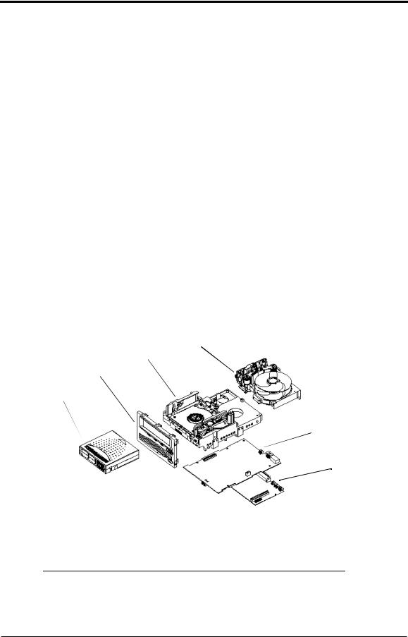
Figure 2-2. SDLT 220/320 Drive System (CAD Diagram in Perspective)
2.3.2 Pivoting Optical Servo
Pivoting Optical Servo (POS) is a Quantum-invented, optically-encoded servo system, which combines high-density magnetic read/write data recording with laser servo guiding. The POS is designed for high-duty-cycle applications, which decreases cost and increases user convenience. The POS enables the head to track dynamic variations in tape motion which allows Quantum to provide a track count with an order of magnitude increase over current DLT products.
2.3.3 Magneto Resistive Cluster Heads
Magneto Resistive Cluster (MRC) heads are a densely packed array of small, costeffective Magneto Resistive (MR) tape heads precisely positioned using advanced thin-film processing technology. SDLT MRC heads provide high wafer usage efficiency resulting in low head costs, are less susceptible to temperature and humidity, yield higher track density and capacity, and provide a multi-channel architecture for increased transfer rate and performance.
2-4 |
March 2004 |
81-85002-01 |

SDLT 220 and SDLT 320 Product Manual |
CHAPTER 2: SDLT 220/320 Product Information |
|
|
2.3.4 Advanced Partial Response Maximum
Likelihood
Improving on Partial Response Maximum Likelihood (PRML) technology traditionally used in disk drives and communication systems, Quantum’s advanced PRML channel technology was co-developed with Lucent Technologies to bring new levels of performance and capacity to high-performance linear tape products. This provides high-encoding efficiency recording densities for greater capacity and performance that enables SDLT to substantially increase transfer rates and capacity.
2.3.5 Advanced Metal Powder Media
Advanced Metal Powder (AMP) media is a state-of-the-art media using durable metal powder technology for recording very high densities of data. The back side of the AMP media receives a specially formulated coating to accept the optical servo tracks. Because the servo information is on the back side of the media, the entire data-bearing side of the media is available for recording data and eliminate the need for pre-formatting. In addition, AMP media has been designed to meet the needs of multiple generations of the SDLT technology.
2.3.6 Positive Engagement
Positive engagement is a highly robust tape leader-buckling mechanism that increases cartridge life and supports the heavy duty-cycle environments found in high-end and automation environments.
This mechanism engages the tape leaders upon cartridge load and disengages them upon cartridge unload. It uses a solid metal pin that is attached to the drive leader to link with molded clips that are permanently attached to the tape leader inside the cartridge. The Positive Leader Link design makes the buckling of Super DLTtape I media a totally reliable mechanical process.
In addition to supporting Super DLTtape I data cartridges, the buckling mechanism also supports existing DLTtape IV data cartridges to ensure complete backwardread compatibility.
81-85002-01 |
March 2004 |
2-5 |
CHAPTER 2: SDLT 220/320 Product Information |
SDLT 220 and SDLT 320 Product Manual |
|
|
2.4 SDLT 220/320 Modular Design
SDLT is designed as a total system. The system includes a complex interaction of a number of important components including such items as the tape path, tape heads, media, cartridge, and host interface.
SDLT is organized into five distinct modules (Figure 2-3) as follows:
•Data Control Module (DCM)
•Tape Control Module (TCM)
•Front Panel Module (FPM)
•Electronic Interface Module (EIM)
•Super DLTtape I Data Cartridge
The modular concept makes the SDLT system easy to manufacture and configure. Each module is optimized to perform a specific set of functions and designed to interface with the other modules in a well-defined and flexible manner. The following subsections provide a brief overview of each module.
DCM
TCM
FPM
Data
Cartridge
EIM ICM
EIM HIM
Figure 2-3. SDLT 220/320 Modular Design
NOTE: Despite the deliberate modularity of each module, with the exception of the data cartridge and the FPM, individual users should not “swap” modules. The data cartridge and
2-6 |
March 2004 |
81-85002-01 |

SDLT 220 and SDLT 320 Product Manual |
CHAPTER 2: SDLT 220/320 Product Information |
|
|
the FPM are the only two modules that are field replaceable. Customer adjustments to the TCM, DCM, or EIM are not allowed, and will void the drive’s warranty.
2.4.1 Data Control Module
The Data Control Module (DCM) contains several of the functions and features of Quantum’s LGMR technology, which is at the heart of the SDLT technology. Of the five technologies that constitute the LGMR technology, two are found in the DCM. These are the POS and the MRC heads.
The main functions of the DCM are to provide the path and guides for all the tape motion inside the drive and to write data to and read data from the tape. In addition to the POS and MRC heads described in Section 2.3.2, “Pivoting Optical Servo” on page 2-4 and Section 2.3.3, “Magneto Resistive Cluster Heads” on page 2-4, the DCM contains a number of components that interact to perform these functions. These components include the advanced head guide assembly, take-up reel, drive motor, the optical servo system, and the tape heads.
The SDLT system tape path, from the first tape guide through the take up reel and motor, has been simplified and improved from the previous DLT systems. The addition of servo technology in the POS system has allowed Quantum engineers to reduce the number of tape guides from six to four. This provides a simpler tape path in the SDLT tape drive, improving performance and reliability.
In addition to its mechanical components, the DCM also contains printed circuit boards that control the functions of the DCM and the tape heads.
81-85002-01 |
March 2004 |
2-7 |

CHAPTER 2: SDLT 220/320 Product Information |
SDLT 220 and SDLT 320 Product Manual |
|
|
2.4.2 Tape Control Module
The Tape Control Module (TCM) implements the functions required to buckle and unbuckle the tape and control the tape motion. The TCM consists of a variety of components:
•TCM PCBA (Printed Circuit Board Assembly)
•Base Plate
•Cartridge Receiver
•Positive Engagement Tape Leader Buckling Mechanism.
Other components include the tape supply motor assembly and the floor plate assembly.
TCM PCBA
The TCM has its own Printed Circuit Board Assembly (PCBA) that controls the functions of the TCM and interfaces with the main controller board in the EIM. By designing the TCM as a distinct module, it allows the TCM to be manufactured and tested as a stand-alone module, simplifying the design, manufacturing and troubleshooting processes.
Base Plate
The SDLT base plate is an aluminum die casting with precisely machined surfaces that acts as the support platform for the other modules and for the drive enclosure. The base plate also includes the precision mounting holes used to install SDLT tape drives into a server or tape library. The SDLT base plate, and therefore the entire SDLT drive, conforms to the 5.25 inch, full-height form factor. This means that SDLT tape drives are a little shorter, at the standard 8 inches, than the previous generation DLT products.
Cartridge Receiver
On tape insertion, the cartridge receiver assembly guides the tape into its operating position, opens the cartridge door, unlocks the cartridge brakes, engages the cartridge drive motor, and secures the tape for operation. On tape ejection, the
2-8 |
March 2004 |
81-85002-01 |

SDLT 220 and SDLT 320 Product Manual |
CHAPTER 2: SDLT 220/320 Product Information |
|
|
cartridge receiver assembly reverses the process and automatically ejects the tape a fixed distance from the front of the drive. There is no longer a manual lock and release handle to operate when loading and unloading the cartridge. This “soft load” capability makes SDLT easier for customers to use in both stand-alone applications and automated tape libraries.
Positive Engagement Tape Leader Buckling Mechanism
This design for SDLT uses a solid metal pin attached to the drive leader which positively links with molded clips that are permanently attached to the tape leader inside the cartridge. The buckling mechanism is responsible for engaging the tape leaders upon cartridge load and disengaging them on cartridge unload.
The SDLT buckling mechanism has been designed to work with the new leaders of the Super DLTtape design as well as the leaders of the previous DLTtape design, allowing backward-read compatibility (BRC) of DLTtape IV cartridges in the SDLT system.
2.4.3 Front Panel Module
The Front Panel Module (FPM) of the system (sometimes referred to as the bezel) performs a number of functions. The functions of the SDLT FPM include:
•Protecting the front of the TCM from physical damage
•Channeling airflow through the system
•Aligning the cartridge when it is inserted into the system
•Providing system status and information through LEDs
•Enabling cartridge ejection
•Delivering the overall cosmetic look of the system.
The FPM is a single module with lenses for the system’s LEDs and a button to activate the drive eject switch. Unlike previous generations of DLT, the SDLT front panel contains no electronics.
81-85002-01 |
March 2004 |
2-9 |

CHAPTER 2: SDLT 220/320 Product Information |
SDLT 220 and SDLT 320 Product Manual |
|
|
2.4.4 Electronic Interface Module
The Electronic Interface Module (EIM) is the electronic heart of the SDLT system. It provides the main control function for the system and the interface from the system to the host computer. The EIM provides the Advanced PRML feature of Quantum’s SDLT technology; advanced PRML is described in “Advanced Partial Response Maximum Likelihood” on page 2-5.
The EIM consists of two major boards: the Integrated Controller Module (ICM), and a separate Host Interface Module (HIM). The ICM contains the main controller and servo micro-processor, the custom-designed SDLT ASICs and the cache memory while the HIM implements the interface between the host system and the drive. This allows easy configuration of the drive to match different host interfaces by simply substituting the appropriate HIM card.
As with the other major modules of the SDLT technology, the EIM has been designed to be manufactured and tested as a distinct module.
2.4.5 Super DLTtape I Data Cartridge Module
As with all tape technologies, the Super DLTtape I data cartridge is a key part of the overall system. The main function of the data cartridge is to provide the magnetic recording media used by the system to store customer information. The data cartridge also provides the protective cartridge that allows the media to be removed and stored safely.
From the outside, the Super DLTtape I data cartridge looks very similar to the DLTtape IV data cartridges. The basic geometry, write protection switch, and label space are unchanged from the DLTtape IV data cartridge. This simplifies the integration of SDLT into existing operating environments and into automated tape libraries. The Super DLTtape I data cartridge is easy to recognize; it has a different color than the DLTtape IV data cartridge and contains a distinctive pattern molded into the shell.
The Super DLTtape I data cartridge has a new, more rugged design that includes a thicker internal circular wall surrounding the media and more structural ribbing to increase overall cartridge resilience and reduce potential damage to the cartridge if it should be dropped. New, wear-resistant materials reduce the potential for debris generation and increase the life of the cartridge.
2-10 |
March 2004 |
81-85002-01 |
Loading...