


ORDER NO.
RRV2309
DVD TUNER
XV-DV55
THIS MANUAL IS APPLICABLE TO THE FOLLOWING MODEL(S) AND TYPE(S).
Type |
Model |
Power Requirement |
Regional restriction |
Remarks |
|
|
codes(Region N0.) |
||||
XV-DV55 |
|||||
|
|
|
|||
|
|
|
|
||
|
|
|
|
|
|
AUCXJ |
O |
AC power supplied from power trans former’s |
1 |
|
|
secondary of other system component. |
|
||||
|
|
|
|
|
|
ADXJ/RA |
O |
AC power supplied from power trans former’s |
1 |
|
|
secondary of other system component. |
|
||||
|
|
|
|
|
|
APWXJ |
O |
AC power supplied from power trans former’s |
4 |
|
|
secondary of other system component. |
|
||||
|
|
|
|
||
|
|
|
|
|
|
AVXJ |
O |
AC power supplied from power trans former’s |
2 |
|
|
secondary of other system component. |
|
||||
|
|
|
|
||
|
|
|
|
|
|
AYXJ |
O |
AC power supplied from power trans former’s |
2 |
|
|
secondary of other system component. |
|
||||
|
|
|
|
||
|
|
|
|
|
 This product is component of system.
|
Component |
Model |
Service Manual |
Remarks |
|
|
|
|
|
DVD SURROUND SYSTEM |
- |
- |
|
|
|
|
|
|
|
|
DVD TUNER |
XV-DV55 |
RRV2309 |
This service manual |
|
|
|
|
|
|
POWERED SUBWOOFER |
S-DV55SW-K |
RRV2310 |
|
|
|
|
|
|
|
SATELLITE SPEAKER |
S-DV55ST-K |
RRV2306 |
|
CONTENTS
1. |
SAFETY INFORMATION ....................................... |
2 |
7.1.2 TEST POINTS LOCATIONS..................... |
63 |
|
2. EXPLODED VIEWS AND PARTS LIST ................. |
4 |
7.1.3 TEST MODE SCREEN DISPLAY ........... |
64 |
||
3. BLOCK DIAGRAM AND SCHEMATIC DIAGRAM .. 12 |
7.1.4 POWER ON SEQUENCE......................... |
66 |
|||
4. |
PCB CONNECTION DIAGRAM ........................... 41 |
7.1.5 TROUBLE SHOOTING ............................ |
67 |
||
5. PCB PARTS LIST ................................................ |
54 |
7.1.6 SINGLE OPERATION METHOD .............. |
68 |
||
6. ADJUSTMENT ..................................................... |
61 |
7.1.7 TEST MODE (FOR SERVICE) ................. |
69 |
||
7. |
GENERAL INFORMATION .................................. 62 |
7.1.8 ERROR CODE ......................................... |
70 |
||
|
7.1 DIAGNOSIS ................................................... |
62 |
7.1.9 DISASSEMBLY ........................................ |
74 |
|
|
7.1.1 SELF-DIAGNOSTIC FUNCTION OF PICKUP |
7.2 PARTS ........................................................... |
77 |
||
|
DEFECTIVE ............................................. 62 |
7.2.1 IC ............................................................. 77 |
|||
|
|
|
8. PANEL FACILITIES AND SPECIFICATIONS |
....... |
90 |
|
|
|
|
||
PIONEER CORPORATION 4-1, Meguro 1-chome, Meguro-ku, Tokyo 153-8654, Japan PIONEER ELECTRONICS SERVICE, INC. P.O. Box 1760, Long Beach, CA 90801-1760, U.S.A. PIONEER ELECTRONIC NV Haven 1087, Keetberglaan 1, 9120 Melsele, Belgium
PIONEER ELECTRONICS ASIACENTRE PTE. LTD. 253 Alexandra Road, #04-01, Singapore 159936 c PIONEER CORPORATION 2000
T – ZZY JUNE 2000 Printed in Japan
XV-DV55
1. SAFETY INFORMATION
This service manual is intended for qualified service technicians ; it is not meant for the casual do-it- yourselfer. Qualified technicians have the necessary test equipment and tools, and have been trained to properly and safely repair complex products such as those covered by this manual.
Improperly performed repairs can adversely affect the safety and reliability of the product and may void the warranty. If you are not qualified to perform the repair of this product properly and safely, you should not risk trying to do so and refer the repair to a qualified service technician.
WARNING
This product contains lead in solder and certain electrical parts contain chemicals which are known to the state of California to cause cancer, birth defects or other reproductive harm.
Health & Safety Code Section 25249.6 – Proposition 65
NOTICE
(FOR CANADIAN MODEL ONLY)
Fuse symbols  (fast operating fuse) and/or
  (slow operating fuse) on PCB indicate that replacement parts must be of identical designation.
REMARQUE
(POUR MODÈLE CANADIEN SEULEMENT)
Les symboles de fusible  (fusible de type rapide) et/ou
  (fusible de type lent) sur CCI indiquent que les pièces de remplacement doivent avoir la même désignation.
(FOR USA MODEL ONLY)
1. SAFETY PRECAUTIONS
The following check should be performed for the continued protection of the customer and service technician.
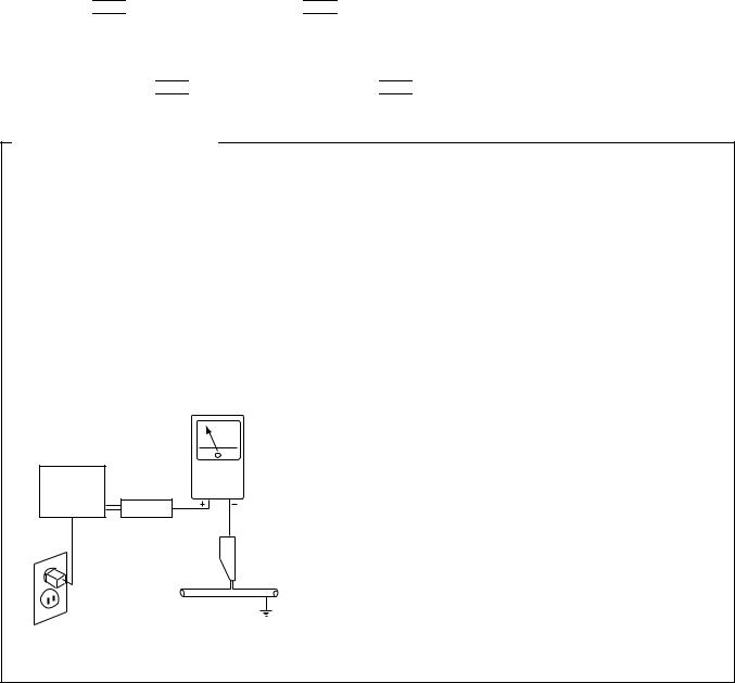
LEAKAGE CURRENT CHECK
Measure leakage current to a known earth ground (water pipe, conduit, etc.) by connecting a leakage current tester such as Simpson Model 229-2 or equivalent between the earth ground and all exposed metal parts of the appliance (input/output terminals, screwheads, metal overlays, control shaft, etc.). Plug the AC line cord of the appliance directly into a 120V AC 60Hz outlet and turn the AC power switch on. Any current measured must not exceed 0.5mA.
|
|
Reading should |
|
Leakage |
not be above |
Device |
current |
0.5mA |
under |
tester |
|
test |
|
|
Test all |
|
|
exposed metal |
|
|
surfaces |
|
|
Also test with |
|
|
plug reversed |
|
Earth |
(Using AC adapter |
|
ground |
plug as required) |
|
|
AC Leakage Test
ANY MEASUREMENTS NOT WITHIN THE LIMITS OUTLINED ABOVE ARE INDICATIVE OF A POTENTIAL SHOCK HAZARD AND MUST BE CORRECTED BEFORE RETURNING THE APPLIANCE TO THE CUSTOMER.
2. PRODUCT SAFETY NOTICE
Many electrical and mechanical parts in the appliance have special safety related characteristics. These are often not evident from visual inspection nor the protection afforded by them necessarily can be obtained by using replacement components rated for voltage, wattage, etc. Replacement parts which have these special safety characteristics are identified in this Service Manual.
Electrical components having such features are identified by marking with a  on the schematics and on the parts list in this Service Manual.
The use of a substitute replacement component which does not have the same safety characteristics as the PIONEER recommended replacement one, shown in the parts list in this Service Manual, may create shock, fire, or other hazards.
Product Safety is continuously under review and new instructions are issued from time to time. For the latest information, always consult the current PIONEER Service Manual. A subscription to, or additional copies of, PIONEER Service Manual may be obtained at a nominal charge from PIONEER.
2
XV-DV55
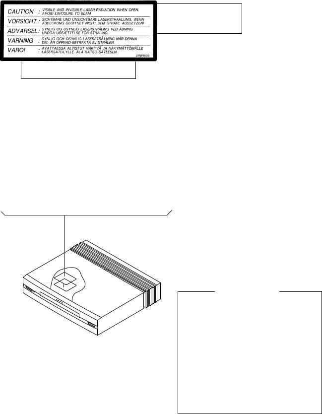
WARNING
THE AEL(ACCESSIBLE EMISSION LEVEL) OF THE LASER POWER OUTPUT IS LESS THAN CLASS 1
BUT THE LASER COMPONENT IS CAPABLE OF EMITTING RADIATION EXCEEDING THE LIMIT FOR
CLASS1.
A SPECIALLY INSTRUCTED PERSON SHOULD DO SERVICING OPERATION OF THE APPARATUS.
LASER DIODE CHARACTERISTICS
FOR DVD : MAXIMUM OUTPUT POWER : 5 mW
WAVELENGTH : 655 nm
FOR CD : MAXIMUM OUTPUT POWER : 5mW
WAVELENGTH : 785 nm
LABEL CHECK
ADXJ/RA, APWXJ, AVXJ and AYXJ only
Additional Laser Caution
1. Inside detection switch (S201 on the SMEB assy) and loadingstatus detection switch (S101 on the LOAB assy) are detected by the microprocessor (IC11 in the DVDM assy).
• To permit the laser diode to oscillate, it is required to set the inside detection switch for the inside position (S201 : ON) and to set the loading-status detection switch for the clamp position (the center terminal of S101 is shorted to +5V). The 655 nm laser diode for DVD oscillation will continue if pin 19 of IC1 is shorted to +5V (fault condition) in the DVDM assy.
The 785 nm laser diode for CD oscillates if pin 20 of IC1 is shorted to +5V in the DVDM assy.
In the test mode , the laser diode oscillates when microprocessor detects a PLAY signal, or when the PLAY key is pressed (S5924 ON in the KEYB assy), with the above requirements satisfied.
2. When the cover is open, close viewing through the objective lens with the naked eye will cause exposure to the laser beam.
: See page 69.
3
XV-DV55
2. EXPLODED VIEWS AND PARTS LIST
NOTES: |
∙ Parts marked by "NSP" are generally unavailable because they are not in our Master Spare Parts List. |
|
|||||
|
∙ The |
mark found on some component parts indicates the importance of the safety factor of the part. |
|
||||
|
Therefore, when replacing, be sure to use parts of identical designation. |
|
|
|
|
||
|
∙ Screws adjacent to |
mark on the product are used for disassembly. |
|
|
|
|
|
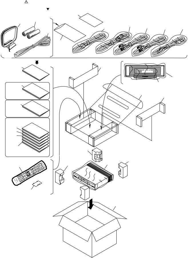
2.1 PACKING |
15 |
|
|
|
|
||
|
16 |
19 |
|
|
|
|
|
|
|
|
4 |
|
|
|
|
|
|
|
18 |
3 |
2 |
1 |
|
|
|
|
|
||||
|
|
|
5 |
|
|
|
|
|
|
|
20 |
|
|
|
|
6 |
29 |
|
25
7 |
27 |
AUCXJ, |
|
AVXJ, |
24 |
AYXJ type only |
29 |
8
ADXJ/RA,
APWXJ type only
9
10 
11
12
13
14 |
22(1/2) |
AYXJ type only
|
21(1/2) |
26 |
22(2/2) |
17 |
|
||
|
|
28
 21(2/2)
23
4

XV-DV55
(1) PACKING PARTS LIST
Mark No. |
Description |
Part No. |
|||
|
1 |
Display Cable (10P Din) |
|
|
ADE7014 |
2 |
Control Cable A (Blue) (10P) |
See Contrast table (2) |
|||
3 |
Control Cable B (Black) (12P) |
See Contrast table (2) |
|||
4 |
AC Power Cord |
See Contrast table (2) |
|||
5 |
FM Antena |
See Contrast table (2) |
|||
6 |
Operating Instructions (Basic) |
See Contrast table (2) |
|||
|
|
(English/Flanch) |
|
||
7 |
Operating Instructions |
See Contrast table (2) |
|||
|
|
(English/Flanch) |
|
||
8 |
Operating Instructions |
See Contrast table (2) |
|||
|
|
(English) |
|
||
9 |
Operating Instructions |
See Contrast table (2) |
|||
|
|
(Dutch/Italian) |
|
||
10 |
Operating Instructions |
See Contrast table (2) |
|||
|
|
(Dutch/Spanish) |
|
||
11 |
Operating Instructions (Basic) |
See Contrast table (2) |
|||
|
|
(Dutch/Italian) |
|
||
12 |
Operating Instructions (Basic) |
See Contrast table (2) |
|||
|
|
(Dutch/Spanish) |
|
||
13 |
Operating Instructions |
See Contrast table (2) |
|||
|
|
(Swedish/Portuguese) |
|
||
14 |
Operating Instructions (Basic) |
See Contrast table (2) |
|||
|
|
(Swedish/Portuguese) |
|
||
Mark |
No. |
Description |
|
Part No. |
NSP |
15 |
Warranty Card |
|
See Contrast table (2) |
|
16 |
AM Loop Antenna |
|
ATB7009 |
|
17 |
Remote Control Unit |
|
See Contrast table (2) |
|
18 |
Video cable |
|
VDE1053 |
NSP |
19 |
Alkaline battery(AA/LR6) 2p |
|
VEM1021 |
NSP |
20 |
Polyethylene Bag |
|
Z21-038 |
|
|
(340 x 230 x 0.03) |
|
|
|
21 |
Pad Front(Pls) |
|
AHA7291 |
|
22 |
Pad Rear(Pls) |
|
AHA7292 |
|
23 |
Packing Case |
|
See Contrast table (2) |
|
24 |
Accessory Case |
|
AHD7877 |
|
25 |
Packing Sheet(300 x 350 x 0.5) AHG7073 |
||
|
26 |
Sheet (650 x 550 x 0.2) |
|
Z23-022 |
|
27 |
Display Unit |
|
AXX7075 |
|
28 |
Battery Cover |
|
AZN7826 |
|
29 |
Partition |
|
See Contrast table (2) |
(2) CONTRAST TABLE
AUCXJ, ADXJ/RA, APWXJ, AVXJ and AYXJ types are constructed the same except for the following:
Mark |
No. |
Symbol and Description |
|
|
Part No. |
|
|
|
|
|
|
|
|
|
Remarks |
||||
AUCXJ |
ADXJ/RA |
APWXJ |
AVXJ |
AYXJ |
|||||
|
|
|
|||||||
|
|
|
|
||||||
|
|
|
type |
type |
type |
type |
type |
|
|
|
|
|
|
|
|
|
|
|
|
|
2 |
Control Cable A (Blue) (10P) |
ADE7061 |
ADE7061 |
ADE7061 |
ADE7062 |
ADE7062 |
|
|
|
3 |
Control Cable B (Black) (12P) |
ADE7063 |
ADE7063 |
ADE7063 |
ADE7064 |
ADE7064 |
|
|
|
4 |
AC Power Cord |
ADG7022 |
ADG1158 |
ADG1160 |
ADG1156 |
ADG1154 |
|
|
|
5 |
FM Antena |
ADH7004 |
ADH7004 |
ADH7004 |
ADH7005 |
ADH7005 |
|
|
|
6 |
Operating Instructions (Basic) |
ARE7262 |
ARE7262 |
ARE7262 |
ARE7261 |
ARE7261 |
|
|
|
|
(English/Flanch) |
|
|
|
|
|
|
|
|
7 |
Operating Instruction |
ARE7260 |
Not used |
Not used |
ARE7259 |
ARE7259 |
|
|
|
|
(English/Flanch) |
|
|
|
|
|
|
|
|
8 |
Operating Instructions |
Not used |
ARB7228 |
ARB7228 |
Not used |
Not used |
|
|
|
|
(English) |
|
|
|
|
|
|
|
|
9 |
Operating Instructions |
Not used |
Not used |
Not used |
Not used |
ARC7303 |
|
|
|
|
(Dutch/Italian) |
|
|
|
|
|
|
|
|
10 |
Operating Instructions |
Not used |
Not used |
Not used |
Not used |
ARC7304 |
|
|
|
|
(Dutch/Spanish) |
|
|
|
|
|
|
|
|
11 |
Operating Instructions (Basic) |
Not used |
Not used |
Not used |
Not used |
ARC7305 |
|
|
|
|
(Dutch/Italian) |
|
|
|
|
|
|
|
|
12 |
Operating Instructions (Basic) |
Not used |
Not used |
Not used |
Not used |
ARC7306 |
|
|
|
|
(Dutch/Spanish) |
|
|
|
|
|
|
|
|
13 |
Operating Instructions |
Not used |
Not used |
Not used |
Not used |
ARC7328 |
|
|
|
|
(Swedish/Portuguese) |
|
|
|
|
|
|
|
|
14 |
Operating Instructions (Basic) |
Not used |
Not used |
Not used |
Not used |
ARC7329 |
|
|
|
|
(Swedish/Portuguese) |
|
|
|
|
|
|
|
NSP |
15 |
Warranty Card |
ARY7045 |
ARY7025 |
ARY7027 |
ARY7022 |
ARY7022 |
|
|
|
17 |
Remote Control Unit |
AXD7264 |
AXD7264 |
AXD7264 |
AXD7265 |
AXD7265 |
|
|
|
23 |
Packing Case |
AHD7943 |
AHD7913 |
AHD7914 |
AHD7911 |
AHD7911 |
|
|
|
29 |
Partition |
AHB7049 |
Not used |
AHB7049 |
AHB7049 |
AHB7049 |
|
|
|
|
|
|
|
|
|
|
|
5
XV-DV55
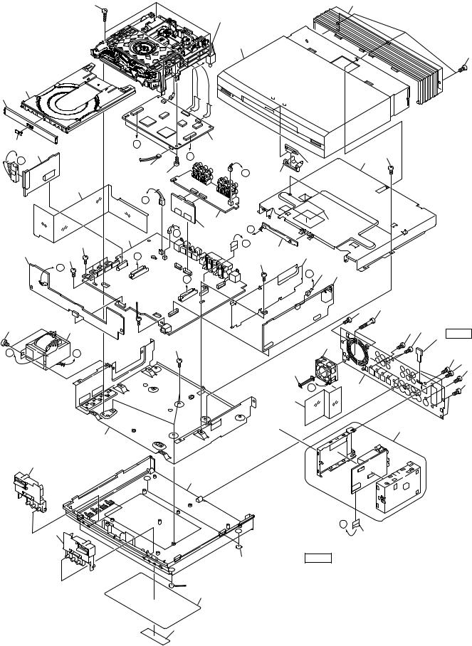
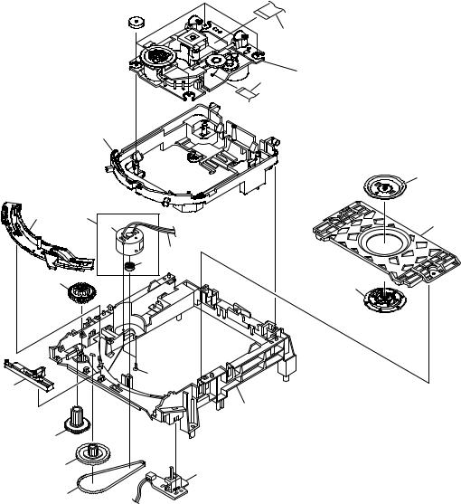
2.2 EXTERIOR
46 |
Refer to |
29 |
|
"2.3 LOADING MECHANISM ASSY". |
|
|
18 |
|
|
30 |
|
49
17
27
33 |
4 |
A |
|
11 |
|
|
|
|
49 |
|
|
To LOAB Assy |
|
B |
|
|
|
21 |
|
||
|
|
|
|
|
|
|
||||
H |
|
CN101 |
|
|
|
|
|
|
||
|
|
|
|
|
34 |
|
|
|||
|
|
16 |
49 |
|
E |
26 |
|
|
|
|
|
|
|
|
|
|
|
|
|||
|
|
|
|
|
|
|
|
|
||
|
24 |
|
|
|
|
|
|
|
|
|
|
|
D |
|
|
|
|
|
|
|
|
|
|
|
|
1 |
|
C |
|
40, 44 |
|
|
|
|
2 |
G |
5 |
|
|
|
|
|
|
|
|
|
|
|
|
|
|
|
||
|
49 |
|
|
F |
|
|
|
|
|
|
|
|
|
|
8 |
|
|
|
|
||
3 |
49 |
A |
|
|
|
45 |
|
|
|
|
|
|
|
49 |
|
|
|
||||
|
|
|
|
|
|
|
|
|||
|
C |
|
|
|
|
|
|
|
|
|
|
|
|
|
|
|
E |
37 6 |
|
|
|
|
|
|
|
B |
|
|
|
|
||
|
|
|
|
|
|
|
|
|
|
|
|
|
49 |
|
|
|
|
|
|
|
|
|
|
|
|
|
|
|
|
49 |
47 |
|
|
|
|
|
|
|
|
|
|
|
|
48 |
13 |
|
|
|
|
|
|
|
50 |
49 |
|
|
|
|
|
|
|
|
|
|
38 NOTE |
|
|
|
49 |
|
|
|
|
15 |
|
|
H |
D |
|
|
|
|
|
|
|
50 |
|
|
|
|
|
|
|
|
|
|||
|
|
|
|
|
|
|
|
|
|
49 |
|
|
|
|
|
|
|
22 |
|
|
50 |
|
|
|
|
|
|
|
|
|
|
|
|
|
|
|
|
|
|
G |
19 |
|
49 |
|
|
|
|
|
|
|
|
|
||
|
|
|
|
|
|
|
25 |
|
|
|
|
|
|
|
|
|
|
|
|
10 |
|
|
|
20 |
|
|
|
|
|
|
|
|
|
31 |
|
|
|
|
|
|
|
|
|
|
|
|
|
28 |
|
|
|
|
|
|
32 |
|
F |
|
14 |
|
|
|
|
|
36 |
NOTE |
|
Parts of No.38 do no service part |
|
|
|
|
|
36 |
partially of the PCB board of AUDIO Assy. |
|
|
|
|
42 |
|
|
43 |
|
6
|
|
|
|
|
|
|
|
|
XV-DV55 |
∙ EXTERIOR PARTS LIST |
|
|
|
|
|
|
|
||
Mark |
No. |
Description |
|
Part No. |
Mark |
No. |
Description |
|
Part No. |
|
1 |
AJKB ASSY |
|
See Contrast table (2) |
|
26 |
Lens Holder(Pls) |
|
AMR7320 |
|
2 |
MOTHER ASSY |
|
See Contrast table (2) |
|
27 |
Tray Panel(Pls) |
|
AAN7199 |
|
3 |
KEYB ASSY |
|
AWU7675 |
|
28 |
Bottom Base(Pls) |
|
AMA7019 |
|
4 |
REGULATOR ASSY |
|
AWU7676 |
|
29 |
Bonnet(Pls) |
|
AMA7020 |
|
5 |
TRADE ASSY |
|
AWU7677 |
|
30 |
Top Panel(Pls) |
|
See Contrast table (2) |
|
6 |
DSP ASSY |
|
See Contrast table (2) |
|
31 |
Button Assy A |
|
AXG7100 |
|
7 |
• • • • • |
|
|
|
32 |
Button Assy B |
|
AXG7101 |
|
8 |
BLED ASSY |
|
AWU7680 |
|
33 |
DVD Plate (Ni) |
|
VAM1077 |
|
9 |
• • • • • |
|
|
|
34 |
Illumination Lens |
|
VNK4168 |
|
10 |
TUNER MODULE |
|
See Contrast table (2) |
|
35 |
• • • • • |
|
|
|
11 |
DVDM ASSY |
|
AWX7724 |
|
36 |
Leg |
|
AEB7090 |
|
12 |
• • • • • |
|
|
|
37 |
Connector Assy 3p |
|
ADE7068 |
|
13 |
Power Transformer |
|
ATT7068 |
NSP |
38 |
Spacer |
|
• • • • • |
|
14 |
13p F•F•C/60v |
|
ADD7246 |
|
39 |
• • • • • |
|
|
|
15 |
DC Fan Motor |
|
AXM7014 |
NSP |
40 |
Fuse Caution |
|
See Contrast table (2) |
|
16 |
Connector Ass’y |
|
PG03KK-E07 |
|
41 |
• • • • • |
|
|
|
17 |
Tray |
|
VNL1858 |
|
42 |
Name Label |
|
See Contrast table (2) |
NSP |
18 |
Loading Mechanism Ass’y |
|
VWT1174 |
NSP |
43 |
Label |
|
See Contrast table (2) |
|
19 |
Rear Panel(Mtl) |
|
See Contrast table (2) |
|
44 |
Caution Label |
|
See Contrast table (2) |
NSP |
20 |
Bottom Plate(Mtl) |
|
ANF7023 |
|
45 |
DSP Shield |
|
See Contrast table (2) |
NSP |
21 |
Top Plate(Mtl) |
|
ANF7024 |
|
46 |
Screw |
|
BBZ30P180FMC |
|
22 |
Fan Plate (Fe) |
|
ANG7153 |
|
47 |
Screw |
|
BBZ30P300FZK |
|
23 |
• • • • • |
|
|
|
48 |
Screw |
|
BBZ40P060FMC |
|
24 |
Power Barrier(Pls) |
|
AEC7271 |
|
49 |
Screw |
|
BPZ30P080FMC |
|
25 |
Fan Barrier(Pls) |
|
AEC7292 |
|
50 |
Screw |
|
PSC30P080FNI |
(2) CONTRAST TABLE
AUCXJ, ADXJ/RA, APWXJ, AVXJ and AYXJ types are constructed the same except for the following:
Mark |
No. |
Symbol and Description |
|
|
|
Part No. |
|
|
|
|
|
|
|
|
|
Remarks |
|||
|
AUCXJ |
ADXJ/RA |
APWXJ |
AVXJ |
AYXJ |
||||
|
|
|
|
||||||
|
|
|
|
|
|||||
|
|
|
|
type |
type |
type |
type |
type |
|
|
|
|
|
|
|
|
|
|
|
|
1 |
AJKB ASSY |
AWU7641 |
AWU7641 |
AWU7641 |
AWU7670 |
AWU7670 |
|
|
|
2 |
MOTHER ASSY |
AWU7674 |
AWU7650 |
AWU7651 |
AWU7648 |
AWU7648 |
|
|
|
6 |
DSP ASSY |
AWU7640 |
AWU7640 |
AWU7640 |
AWU7669 |
AWU7669 |
|
|
|
10 |
TUNER MODULE |
AXQ7228 |
AXQ7228 |
AXQ7228 |
AXQ7229 |
AXQ7229 |
|
|
|
19 |
Rear Panel(Mtl) |
ANC7919 |
ANC7956 |
ANC7957 |
ANC7920 |
ANC7920 |
|
|
|
30 |
Top Panel |
AMB7734 |
AMB7703 |
AMB7734 |
AMB7734 |
AMB7734 |
|
|
NSP |
40 |
Fuse Caution |
AAX7808 |
Not used |
Not used |
Not used |
Not used |
|
|
|
42 |
Name Label |
ARW7097 |
ARW7100 |
ARW7098 |
ARW7098 |
ARW7098 |
|
|
NSP |
43 |
Label |
VRW1629 |
Not used |
Not used |
Not used |
Not used |
|
|
|
44 |
Caution Label |
Not used |
VRW1699 |
VRW1699 |
VRW1699 |
VRW1699 |
|
|
|
45 |
DSP Shield |
Not used |
Not used |
Not used |
ANG7320 |
ANG7320 |
|
|
|
|
|
|
|
|
|
|
|
|
7
XV-DV55
2.3 LOADING MECHANISM ASSY
To DVDM Assy
CN4
17

18 |
|
1 |
Refer to |
15 |
"2.4 TRAVERSE MECHANISM ASSY-S". |
|
To DVDM Assy
CN3
16
|
|
|
20 |
3 |
11 |
|
22 |
|
12 |
To DVDM Assy |
|
|
|
|
|
|
|
CN2 |
|
|
4 |
14 |
|
|
|
13 |
|
|
4 |
|
21 |
|
|
|
|
9 |
5 |
|
|
6 |
10 |
|
8 |
2 |
|
|
7 |
|
 LOADING MECHANISM ASSY PARTS LIST
Mark |
No. |
Description |
|
Part No. |
Mark No. |
Description |
Part No. |
||
|
1 |
Traverse Mechanism Assy-S |
|
VXX2653 |
|
11 |
Loading Motor Assy |
|
VXX2505 |
NSP |
2 |
LOAB Assy |
|
VWG2171 |
12 |
DC Motor / 0.3W (LOADING) |
PXM1027 |
||
|
3 |
Drive Cam |
|
VNL1862 |
13 |
Motor Pulley |
PNW1634 |
||
|
4 |
Drive Gear |
|
VNL1861 |
14 |
Connector Assy |
VKP2253 |
||
|
5 |
Lock Plate |
|
VNL1820 |
15 |
Flexible Cable (08P) |
VDA1822 (or VDA1818) |
||
|
6 |
Loading Base |
|
VNL1863 |
16 |
Float Base |
VNL1865 |
||
|
7 |
Belt |
|
VEB1315 (or VEB1320) |
17 |
Floating Rubber |
VEB1286 |
||
|
8 |
Gear Pulley |
|
VNL1866 |
18 |
Flexible Cable (24P) |
VDA1821 (or VDA1820) |
||
|
9 |
Screw |
|
JGZ17P028FMC |
19 |
• • • • • |
|
||
|
10 |
Loading Gear |
|
VNL1860 |
20 |
Clamper Plate |
VNE2162 |
||
|
|
|
|
|
21 |
Clamper |
VNL1738 |
||
|
|
|
|
|
22 |
Bridge |
VNL1859 |
||
8
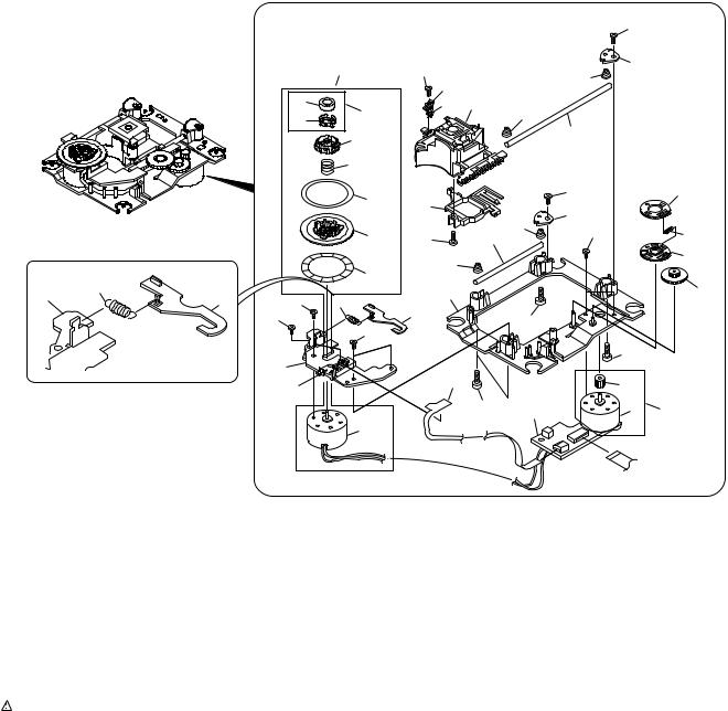
2.4 TRAVERSE MECHANISM ASSY-S
∙ Top View
|
|
|
35 |
|
|
30 |
34 |
|
|
16 |
|
|
|
|
|
|
|
|
19 |
|
|
|
8 |
|
|
|
6 |
|
|
|
20 |
|
9 |
|
12 |
|
|
|
|
17 |
21 |
31 |
9 |
|
|
||
|
|
37 |
|
|
|
|
37 |
17
24
4
XV-DV55
|
|
|
37 |
|
33 |
|
10 |
18 |
|
|
|
|
||
28 |
|
|
|
|
|
|
|
|
|
15 |
5 |
10 |
|
|
|
|
|
|
|
|
|
13 |
|
|
|
|
37 |
|
26 |
22 |
|
18 |
|
|
|
|
|
|
|
|
|
10 |
|
11 |
33 |
14 |
32 |
|
|
|
|
|
||
10 |
|
|
|
25 |
|
|
|
|
|
23 |
|
|
|
27 |
21 |
|
7 |
|
|
|
|
|
|
|
|
|
|
7 |
|
2 |
|
|
29 |
|
|
|
|
|
|
|
7 |
1 |
3 |
36 |
To
DVDM Assy
CN3
 TRAVERSE MECHANISM ASSY-S PARTS LIST
Mark |
No. |
Description |
|
Part No. |
Mark |
No. |
Description |
|
Part No. |
NSP |
1 |
SMEB Assy |
|
VWG2048 |
|
21 |
Hook |
|
VNL1770 |
NSP |
2 |
FGSB Assy |
|
VWG2009 |
|
22 |
FFC Holder |
|
VNL1802 |
NSP |
3 |
Motor (CARRIAGE) |
|
VXM1079 |
|
23 |
Mechanism Base |
|
VNL1806 |
NSP |
4 |
Motor (SPINDLE) |
|
VXM1084 |
|
24 |
FG Holder |
|
VNL1807 |
NSP 5 |
Pickup Assy |
|
VWY1055 |
|
25 |
Gear A |
|
VNL1808 |
|
|
6 |
Table Sheet |
|
DEC2040 |
|
26 |
Gear B |
|
VNL1809 |
|
7 |
Screw |
|
VBA1058 |
|
27 |
Gear C |
|
VNL1810 |
|
8 |
Centering Spring |
|
VBH1278 |
|
28 |
Slider |
|
VNL1811 |
|
9 |
Hook Spring |
|
VBH1317 |
|
29 |
Gear D |
|
VNL1814 |
|
10 |
Skew Spring |
|
VBH1303 |
NSP |
30 |
Magnet |
|
VYM1024 |
|
11 |
Gear Spring |
|
VBH1308 |
|
31 |
Screw |
|
JFZ17P025FZK |
NSP |
12 |
Reflected Sheet |
|
VEC1959 |
|
32 |
Screw |
|
JGZ17P028FMC |
|
13 |
Guide Bar |
|
VLL1504 |
|
33 |
Screw |
|
VBA1051 |
|
14 |
Sub-guide Bar |
|
VLL1505 |
|
34 |
Magnet Holder Assy |
|
VXX2507 |
|
15 |
Hold Spring |
|
VNC1017 |
|
35 |
Spindle Motor Assy |
|
VXX2649 |
NSP |
16 |
Magnet Holder |
|
VNE2070 |
|
36 |
Carriage Motor Assy |
|
VXX2650 |
NSP |
17 |
Motor Base |
|
VNE2154 |
NSP |
37 |
Screw |
|
PBA1069 |
NSP |
18 |
Cover |
|
VNE2155 |
|
|
|
|
|
|
19 |
Centering Ring |
|
VNL1746 |
|
|
|
|
|
NSP |
20 |
Disc Table |
|
VNL1747 |
|
|
|
|
|
9
XV-DV55
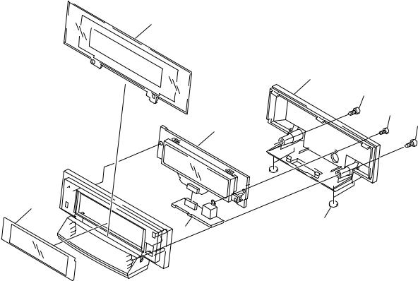
2.5 DISPLAY UNIT
4
7
8
9
8
1
3 


 6 5
6 5 

3
2
∙ DISPLAY UNIT PARTS LIST
Mark No. |
Description |
|
Part No. |
|
|
1 |
FLDP ASSY |
|
AWU7678 |
2 |
CNB ASSY |
|
AWU7679 |
|
3 |
Leg |
|
AEB7090 |
|
4 |
Window (Pls) |
|
AAK7785 |
|
5 |
Fl Filter(Pls) |
|
AEC7272 |
|
6 |
Display Panel(Pls) |
|
AMB7704 |
|
7 |
Display Cover(Pls) |
|
AMC7044 |
|
8 |
Screw |
|
BPZ30P080FMC |
|
9 |
Screw |
|
PSC30P080FNI |
|
10
XV-DV55
11
|
1 |
|
2 |
|
3 |
|
4 |
|
|
|
|
|
|
XV-DV55
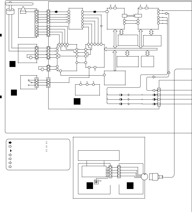
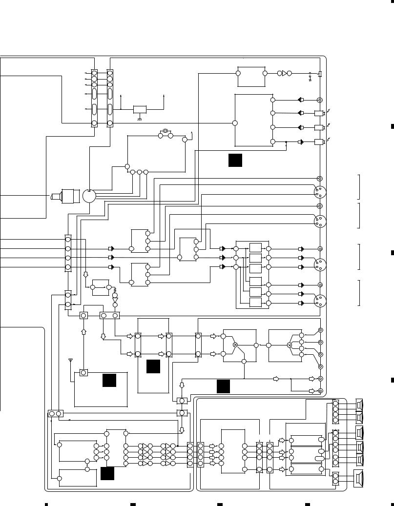
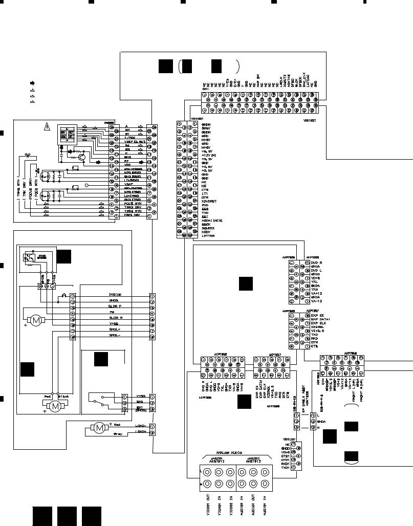
3. BLOCK DIAGRAM AND SCHEMATIC DIAGRAM
3.1 BLOCK DIAGRAM
A
27M |
16M |
27M |
36/16M |
|
|
|
|
(24P) |
|
|
|
|
|
|
|
|
|
|
4 |
107 |
|
|
197 |
205 |
|
|
|
|
(24P) |
CN4 |
|
|
|
|
|
|
|
|
|
|
|
|
AODAI(AC3) |
||||||
Spindle |
OEIC |
15 |
RF |
15 |
|
|
RF |
5 |
|
54 |
RFO |
|
|
|
170 |
|
|
|
|
|
64 |
ADAO |
|
|
RF IC |
|
|
|
|
|
SD0-SD7 |
|
|
62 |
|||||||||||
Motor |
|
22 |
B1 |
22 |
|
|
B1 |
6 |
46 |
DSPRF |
|
|
|
|
DVD |
57-60 |
78,80-84 |
MPEG2 |
|
|||
|
|
|
|
IC1 |
|
|
|
|
|
|
|
|||||||||||
|
|
23 |
B2 |
23 |
|
|
B2 |
7 |
|
BH |
|
|
|
DECODER |
63-66 |
|
86,87 |
DECODER |
45 |
VOUT |
||
|
|
B3 |
|
|
B3 |
LA9701M 56 |
PH |
|
|
|
BY CHIP |
|
SREQ |
|
AV-1 |
YOUT |
||||||
|
|
18 |
18 |
|
|
B4 |
8 |
|
57 |
|
|
|
|
|
56 |
91 |
|
39 |
||||
|
|
19 |
B4 |
19 |
|
|
9 |
|
|
|
|
|
|
IC12 |
|
IC18 |
COUT |
|||||
|
PICKUP |
|
|
|
FE |
|
|
|
|
|
XSACK |
|
36 |
|||||||||
|
|
|
|
|
|
42 |
|
|
|
|
55 |
89 |
||||||||||
|
|
|
|
|
|
|
|
|
|
|
|
PE5108A |
|
MB86373B |
|
|||||||
|
ASSY |
4 |
F RTN |
4 |
|
|
|
|
|
TE |
|
|
|
|
|
|
|
|
||||
|
|
|
|
|
|
|
|
|
35 |
|
|
|
|
Q105 |
|
|
|
|
|
|
|
|
|
|
|
F DRV |
|
|
|
|
|
|
|
|
|
|
|
|
|
|
|
|
|
||
|
|
1 |
1 |
|
|
|
|
|
|
|
|
|
|
|
|
|
|
|
|
|
|
|
|
|
|
|
|
|
|
|
|
|
|
|
|
|
|
|
|
|
|
|
|
||
|
|
3 |
T DRV |
3 |
|
|
|
|
|
|
|
|
|
|
|
|
|
|
|
|
|
|
|
|
|
|
|
|
|
|
|
|
|
|
|
|
|
|
|
|
|
|
|
||
|
|
2 |
T RTN |
2 |
|
|
|
|
|
|
|
|
|
|
|
|
|
|
|
|
|
|
|
|
|
|
|
|
|
|
|
|
|
|
|
|
|
|
|
|
|
|
|
||
|
|
|
|
|
|
|
|
|
|
|
|
|
|
|
|
|
4M DRAM |
|
16M SDRAM |
|
||
|
|
|
|
|
|
|
|
|
|
|
|
|
|
|
|
|
IC15 |
|
IC19 |
|
|
|
|
|
CN202 |
|
(8P) |
|
|
|
|
|
|
|
|
|
|
|
MN414800CSJ-07 |
MB811171622A |
|
||||
|
|
|
CN30 |
13 |
12 |
10 |
9 |
|
|
32 |
33 |
30 |
31 |
39 |
|
|
|
|
-100FN |
|
|
|
|
|
|
|
|
|
|
|
|
|
|
|
|
|
|||||||||
|
(8P) |
7 |
SPDL+ |
7 |
31 |
|
|
FDO |
|
|
|
|
|
|
|
|
|
|
|
|
3 |
47 |
|
|
|
|
|
|
|
||||
|
|
8 |
SPDL- |
8 |
32 |
|
|
|
|
|
|
|
|
|
||
|
|
|
|
TDO |
|
|
|
|
|
|
|
|
||||
|
|
|
|
20 |
48 |
|
|
|
|
|
|
|
||||
|
|
|
SLDR R |
|
|
|
|
|
|
|
|
|
|
|
||
|
|
5 |
5 |
34 |
|
|
SLDO 45 |
|
|
|
|
|
|
|
||
|
|
|
|
17 |
|
|
|
|
|
|
|
|||||
|
- M + |
3 |
SLDR F |
3 |
35 |
SPDL & FTS |
SERVO DSP |
|
|
WORK SRAM |
FLASH |
|
||||
|
|
|
|
|
|
|
||||||||||
|
Carriage |
|
|
|
|
DRIVER |
|
SPDO 46 |
|
IC2 |
|
|
(1M) |
MEMORY |
|
|
|
Motor |
|
|
|
(2P) |
IC3 |
28 |
|
LC78652W |
|
|
IC14 |
IC13 |
|
||
|
B SMEB ASSY |
|
|
|
CN2 |
|
|
|
|
|
|
|
|
|||
B |
|
|
1 |
LOAD- 15 |
M56788FP |
|
|
|
84 |
14 |
|
KM68V1000CLT-7L |
AYW7005 |
|
||
|
Loading |
- M + |
2 |
LOAD+ 14 |
|
|
|
|
|
|
|
|
|
|||
|
Motor |
17 |
|
|
|
|
|
|
|
|
|
|
||||
|
|
|
|
|
|
|
|
|
|
16M |
|
|
|
|
|
|
|
|
|
|
|
|
LODDRV |
|
|
|
|
SYSTEM |
|
|
|
||
|
|
|
|
|
(3P) |
|
|
|
|
|
|
|
|
|||
|
|
|
|
|
|
|
|
|
|
|
42 CONTROL CPU |
|
|
|||
|
CN101 |
|
|
CN1 |
|
|
|
|
|
|
|
|
||||
|
|
|
|
|
|
|
|
|
|
|
|
|
|
|||
|
S101 |
1 |
|
1 |
+3.3V |
|
|
27M |
16M |
36/16M |
|
IC11 |
|
|
|
|
|
Loading |
2 |
|
2 |
LODPOS |
|
|
|
|
|
PD3410A |
|
|
|
||
|
Position |
|
|
|
|
6 |
|
5 |
1 |
|
|
|
|
CN15 |
||
|
3 |
|
3 |
|
|
|
|
|
|
|
|
|||||
|
Switch |
|
GND |
|
|
|
|
|
|
|
||||||
|
|
|
|
|
|
|
CLOCK GENERATOR |
|
|
|
ADATA0 |
(30P) |
||||
|
A LOAB ASSY |
|
|
|
|
|
|
IC21 |
|
|
|
|
23 |
|||
|
|
|
|
|
|
|
|
VOUT |
(V) |
|
(V) |
|||||
|
|
|
|
|
|
CY2081SL-638 |
Q83 |
7 V |
||||||||
|
|
|
|
|
|
|
|
|
|
|
|
|||||
|
|
|
|
|
|
|
D DVDM ASSY |
YOUT |
(Y) |
Q81 |
(Y) |
Y |
||||
|
|
|
|
|
|
|
|
|||||||||
|
|
|
|
|
|
|
|
|
|
11 |
||||||
|
|
|
|
|
|
|
|
|
|
|
||||||
|
|
|
|
|
|
|
|
(C) |
Q85 |
(C) |
9 |
|||||
|
|
|
|
|
|
|
|
|
|
|
|
COUT |
|
C |
||
C
XV-DV55
(DVD TUNER)
|
|
|
(V) |
|
|
|
|
: RF Signal Route |
|
|
|
|
(Y) |
|
|
|
|
: Audio Signal Route (L ch) |
|
|
|
|
|
|
|
(D) |
(C) |
||
|
|
|
: Digital Audio |
|
|
(SL) |
: SL Audio Signal Route (L ch) |
||
|
|
|
||
|
(FL) |
: FL Audio Signal Route (L ch) |
||
|
(C) |
|||
|
: C Audio Signal Route (L ch) |
|||
|
|
|
||
|
(SW) |
: SW Audio Signal Route (L ch) |
||
|
|
|
||
D
 : V Signal Route
 : Y Signal Route
 : C Signal Route
DISPLAY UNIT |
|
|
|
|
||
(AXX7075) |
|
|
|
|
|
|
FL TUBE |
|
|
|
|
|
|
FL DRIVER |
10 |
SR IN |
10 |
|
||
4 |
XFLCS |
|
||||
MSM9202-01 |
FLCK |
4 |
CN5651 |
|||
3 |
3 |
|||||
|
||||||
|
2 |
|
FL |
2 |
|
|
|
DATA |
|
||||
|
|
|
|
|||
CN5652 |
CN5661 |
|
||||
(11P) |
|
|
(11P) |
|
||
L SR |
|
|
|
K |
|
|
CNB ASSY |
|
|
|
FLDP ASSY |
|
|
12
|
1 |
|
2 |
|
3 |
|
4 |
|
|
|
|
|
|
||||
|
|
|
|
|
|
5 |
|
6 |
|
7 |
|
8 |
|
|
|
|
XV-DV55
(30P) |
|
|
(30P) |
|
|
|
|
H.P. AMP |
|
|
CN5 |
|
|
CN8502 |
|
|
|
|
|
||
|
|
|
|
|
8 H.P. VOL 7 |
|
|
|
||
+5V |
2 |
2 |
|
|
|
|
5 |
7 |
JA3901 |
|
M + 6V |
5,7 |
5,7 |
|
|
|
IC3901 |
IC3902 |
HP OUT |
||
|
|
|
M62429FP |
|
||||||
+12V |
9 |
9 |
|
|
|
|
NJM4560M |
|
||
|
|
|
|
|
|
|||||
+3.3V |
8 |
8 |
+2.5V |
VD+3DVD |
|
|
|
(D) |
|
|
10 |
10 |
PQ025EZ5MZP |
|
|
|
|
JA5101 |
|||
|
|
|
|
4 |
||||||
|
|
|
|
|
||||||
|
12 |
12 |
IC8521 |
|
|
DIGITAL INPUT |
|
|
COAXCIAL INPUT |
|
+2.5V |
|
REG |
|
|
|
(D) |
|
|||
| |
| |
|
|
|
SELECTOR |
|
JA5101 |
|||
|
13 |
13 |
|
|
|
|
5 |
|
||
|
|
|
|
|
|
|
||||
|
|
|
|
|
|
|
IC5101 |
|
|
OPTICAL INPUT |
|
26 |
26 |
|
|
|
AODAI 3 |
|
(D) |
|
|
AODAI(AC3) |
AODAI(AC3) |
X5501(10MHz) |
TC74HC153AF |
6 |
JA5102 |
|||||
|
|
|
|
|
|
VU+5V |
|
|
|
OPTICAL INPUT |
|
|
|
|
15 |
16 |
|
|
|
|
|
|
|
|
|
|
|
|
(D) |
|
||
|
|
|
|
|
|
90 |
|
|
JA5151 |
|
|
|
|
|
|
|
|
7 |
|
||
|
|
|
|
|
|
|
|
|
||
|
|
|
|
MICRO COMPUTER |
|
|
|
|
OPTICAL OUTPUT |
|
|
|
|
|
|
|
|
|
(AUDIO1) |
||
|
|
|
|
|
|
|
|
|
|
|
|
|
|
|
|
|
|
|
|
IC5501 |
|
|
|
|
|
|
|
F MOTHER ASSY |
|
|
|
|
||||||||
|
|
|
REMOCON(SR IN) |
|
|
|
|
PDC062 |
|
|
|
|
|
|
|
|
|
|
|
||||||||||
|
|
|
29 |
|
|
|
|
|
|
|
|
|
|
|
|
|
|
|
|
||||||||||
|
|
|
|
|
92 |
93 |
94 |
|
|
|
|
|
|
|
|
|
|
|
|
|
|
|
|
|
|
|
|
||
|
|
|
|
|
XFLCS |
|
FLCK |
|
FLDATA |
|
|
|
|
|
|
|
|
|
|
|
|
|
|
|
|
|
|
COMPOSITE |
|
|
|
CN5591 |
|
|
|
|
|
|
|
|
|
|
|
|
|
|
|
|
|
|
|
|
|
|
|
|
|
VIDEO INPUT |
|
|
|
|
|
|
|
|
|
|
|
|
|
|
|
|
|
|
|
|
|
|
|
|
|
3 |
|
|
|
VIDEO |
|
|
|
|
|
|
|
|
|
|
|
|
|
|
|
|
|
|
|
|
|
|
|
|
|
|
|
|
S VIDEO |
||
|
|
|
|
|
|
|
|
|
|
|
|
|
|
|
|
|
|
|
|
|
|
|
|
|
|
|
|
INPUT 1 |
|
|
|
|
|
|
|
|
|
|
|
|
|
|
|
|
|
|
|
|
|
|
|
|
|
|
4 |
|
|
INPUT |
|
|
|
|
|
|
|
|
|
|
|
|
|
|
|
|
|
|
|
|
|
|
|
|
|
|
|
|
|
||
|
|
|
|
|
|
|
|
|
|
|
|
|
|
|
|
|
|
|
|
|
|
|
|
|
|
|
|
|
|
|
|
|
|
|
|
|
|
|
|
|
|
|
|
|
|
|
|
|
|
|
|
|
|
|
|
|
|
COMPOSITE |
|
|
|
|
|
|
|
|
|
|
|
|
|
|
|
|
|
|
|
|
|
|
|
|
|
|
|
|
|
VIDEO INPUT |
VIDEO |
|
|
|
|
|
|
|
|
|
|
|
|
|
|
|
|
|
|
|
|
|
|
|
|
|
3 |
|
|
|
|
|
|
|
|
|
|
IC5301 |
|
|
|
|
|
|
|
|
|
|
|
|
|
|
|
|
|
S VIDEO |
INPUT 2 |
||||
|
|
|
|
|
|
|
|
|
|
|
|
|
|
|
|
|
|
|
|
|
|
|
|
|
|||||
CN8501 |
|
|
NJM2534M |
|
|
|
|
|
|
|
|
IC5351 |
|
|
|
|
|
4 |
|
|
INPUT |
|
|||||||
|
|
|
|
|
|
|
|
|
|
|
|
|
|
|
|
|
|
|
|
|
|
|
|
|
|||||
|
(30P) |
|
|
|
|
|
VIDEO |
SELECT |
1 |
|
|
VIDEO |
SELECT |
|
|
|
|
LA7135AM |
|
|
|
|
(Y) |
|
|
|
|
MONITOR |
|
|
Y |
|
|
|
|
|
|
|
|
|
|
|
|
VIDEO AMP |
|
|
|
|
|
|
|
|
|||||||
ADATA0 |
23 |
|
|
|
|
|
|
3 |
|
|
|
|
1 |
|
|
|
|
|
|
|
|
|
|
|
JA5351 |
|
|||
|
V |
|
(V) |
|
|
|
|
|
|
|
|
|
|
|
(V) |
|
AMP |
|
|
|
|
(V) |
|
|
|
COMPOSITE |
|
||
|
7 |
5 |
|
|
|
7 |
|
|
|
|
3 |
|
|
|
3 |
23 |
|
|
|
|
|
|
|
||||||
|
|
|
(Y) |
|
|
|
|
|
|
|
|
|
|
|
(Y) |
|
|
|
|
|
|
|
|
|
|
|
VIDEO OUT |
|
|
|
|
|
|
|
|
|
|
|
|
5 |
|
7 |
|
|
|
AMP |
|
|
|
|
|
|
|
|
|
|
|||
|
|
11 |
|
|
|
|
|
|
|
|
|
|
|
|
|
10 |
15 |
|
|
|
|
3 |
|
|
CN501 |
OUTPUT |
|||
|
C |
|
|
|
|
|
|
|
|
|
|
IC5303 |
|
|
|
|
|
|
|
|
(C) |
|
|
||||||
|
9 |
(C) |
5 |
|
VIDEO |
SELECT |
7 |
|
|
|
|
|
6 |
AMP |
19 |
|
|
|
|
|
|
S VIDEO |
|
||||||
|
|
DAC |
|
|
|
|
|
|
|
|
|
|
|
|
(V) |
|
|
|
COMPOSITE |
|
|||||||||
|
|
|
|
|
|
|
|
1 |
|
|
NJM2534M |
|
|
AMP |
|
|
|
|
4 |
|
|
OUTPUT |
|
||||||
|
|
|
IC5401 |
|
|
|
|
3 |
|
|
|
|
|
|
(C) |
|
|
|
|
|
|
|
|
|
|
|
|||
|
|
|
PCM1716E |
|
|
|
|
|
|
|
|
|
|
|
|
|
|
|
|
|
|
|
|
|
|
JA5351 |
|
||
|
|
|
|
|
|
|
|
|
|
|
|
|
|
|
|
|
|
|
|
|
|
|
|
|
|
|
|||
|
|
|
|
|
|
|
|
|
|
|
|
|
|
|
|
|
|
|
|
|
|
|
|
|
|
|
|
|
|
CN5504 |
2 |
16 |
|
|
|
|
|
|
|
|
|
|
|
|
|
|
|
21 |
|
|
|
|
|
|
|
VIDEO OUT |
|
||
|
IC5302 |
|
|
|
|
|
|
|
|
|
AMP |
|
|
|
|
(Y) |
|
|
|
VIDEO |
|||||||||
(11P) |
|
|
|
|
|
|
|
|
|
|
|
|
|
13 |
|
|
|
|
|
|
|
||||||||
|
DIN |
1 |
|
2 |
NJM2534M |
|
|
|
|
|
|
|
|
|
|
|
|
|
|
3 |
|
|
CN501 |
OUTPUT 1 |
|||||
|
|
|
|
|
|
|
|
|
|
|
|
|
|
|
|
(C) |
|
|
|||||||||||
|
|
HP L |
LPF |
IC5421 |
|
|
|
|
|
|
|
|
|
|
|
AMP |
|
|
|
|
|
|
|
S VIDEO |
|
||||
|
|
1 BA4558F |
|
|
|
|
|
|
|
|
|
|
|
17 |
|
|
|
|
|
|
|
|
|||||||
|
|
9 |
|
|
|
|
|
|
|
|
|
|
|
|
|
|
|
|
4 |
|
|
OUTPUT |
|
||||||
|
|
|
|
CN5505 |
|
|
|
|
|
|
|
|
|
|
|
|
|
|
|
|
|
|
|
|
|
|
|||
|
|
7 |
7 |
9 |
|
(11P) |
|
|
|
|
|
|
|
|
|
|
|
|
|
|
|
|
|
|
|
|
|
||
|
|
CN5701 |
LchTX |
LchDVD |
(11P) |
|
|
|
|
(11P) |
|
|
|
(11P) |
|
IC5231 |
|
IC5201 |
|
|
|
JA5201 |
|
||||||
|
|
(13P) |
|
|
|
|
|
|
|
|
|
|
BU4052BCF |
|
BU4052BCF |
|
|
|
ANALOG IN1 |
|
|||||||||
|
|
|
CN5203 |
|
|
CN5202 |
|
|
CN5201 |
|
|
|
|
|
|
||||||||||||||
|
|
|
|
|
|
|
|
|
|
|
|
|
|
||||||||||||||||
|
|
|
|
|
|
|
|
|
|
|
|
|
|
|
|
|
|
|
(VIDEO 1) |
|
|||||||||
|
|
|
|
|
|
|
9 |
|
|
9 |
|
|
|
|
9 |
|
12 |
|
|
|
|
|
|
12 |
|
|
|
||
|
|
|
|
|
|
|
|
DVD Lch |
|
DVD Lch |
|
|
|
|
|
|
|
|
|
|
ANALOG IN2 |
|
|||||||
|
|
|
|
|
|
|
|
|
|
|
|
|
|
|
|
|
|
|
|
|
|
14 |
|
|
|
||||
|
|
|
|
|
|
|
|
|
|
|
|
|
|
|
|
|
|
|
15 |
13 |
|
|
|
|
|
|
(VIDEO 2) |
|
|
|
|
|
|
|
|
|
|
|
|
|
|
|
|
|
|
|
|
|
|
|
|
|
15 |
|
|
|
|||
|
|
|
|
|
|
|
|
|
TX Lch |
|
|
TX Lch |
|
|
|
|
|
|
|
|
|
|
|
|
|
|
ANALOG IN3 |
|
|
|
|
TX |
|
|
|
|
6 |
|
6 |
|
|
|
6 |
|
14 |
|
|
|
|
|
|
11 |
|
|
|
||||
|
|
|
|
|
|
|
|
|
|
|
|
|
|
|
|
|
|
|
|
|
(AUDIO 1) |
|
|||||||
|
|
|
|
|
|
|
|
G |
|
|
|
|
|
|
|
|
|
|
|
|
|
|
|
|
|
|
|||
|
|
|
|
|
|
|
|
|
|
|
|
|
|
|
|
13 |
|
|
|
|
|
|
|
|
|
ANALOG IN4 |
|
||
|
|
|
|
|
|
|
|
|
|
|
|
|
|
AUDIO OUT |
|
|
AUDIO IN |
|
|
|
|
||||||||
|
|
|
|
|
|
|
|
|
|
|
|
|
|
|
|
|
|
|
(AUDIO 2) |
|
|||||||||
|
|
7 |
|
|
|
|
|
|
|
|
|
|
|
SELECTOR |
|
|
SELECTOR |
|
|
|
|
||||||||
|
|
|
J |
|
|
|
|
|
|
|
|
|
|
|
|
|
|
ANALOG OUT1 |
|||||||||||
|
|
CN201 (13P) |
|
|
|
TRADE |
|
|
|
|
|
|
|
|
|
|
|
|
|
|
|
|
|
||||||
|
|
|
|
|
|
|
|
|
|
H AJKB ASSY |
|
|
|
|
|
|
(VIDEO 1) |
|
|||||||||||
|
|
|
TUNER |
|
|
|
ASSY |
|
Lch |
|
|
|
|
|
|
|
|
|
ANALOG OUT2 |
||||||||||
|
|
|
|
|
|
|
|
(3P) |
|
|
|
|
|
|
|
|
|
|
|
|
|
CN3303 |
(AUDIO 1) |
FL |
|||||
|
|
|
MODULE |
|
|
|
|
|
|
|
|
|
|
|
|
|
|
|
|
|
|
|
+ |
||||||
DIN |
HP L |
|
|
|
|
|
|
|
CN5207 |
|
1 |
|
|
|
S-DV55SW |
|
|
|
|
|
|
|
|
|
|
||||
|
|
|
|
|
|
|
|
|
|
|
|
|
|
|
|
|
|
|
|
|
|
- |
SP |
||||||
11 |
3 |
CN3702 (11P) |
|
|
|
|
|
CN3703 (3P) |
|
|
|
|
(POWERED SUBWOOFER) |
|
|
||||||||||||||
|
|
|
|
|
1 |
|
|
|
|
|
+ |
FR |
|||||||||||||||||
|
|
|
|
|
|
|
|
|
|
|
|
|
|
|
|
|
|
|
|
|
|
|
|
|
|
|
|
|
|
|
|
|
|
IC3751 |
|
|
|
|
|
|
|
Lch |
|
|
|
|
|
IC3001 |
|
|
|
|
|
|
|
|
|
- |
SP |
|
|
|
|
|
|
|
|
|
|
|
|
|
|
|
|
|
|
|
|
|
|
|
|
|
|
CN3401 |
|
||
|
|
|
|
AK4527 |
|
|
|
|
|
|
|
|
|
|
|
M62446FP |
|
|
|
|
|
POWER AMP |
CENTER |
||||||
|
|
|
|
9 |
29 |
IC8701,3,5 |
IC8851,3, 5,6 |
|
|
|
(12P) |
|
6ch |
(20P) |
|
(20P) |
|
|
|
|
|
|
+ |
||||||
|
|
|
|
6ch |
|
|
|
|
|
CN3501 CN3301 |
|
|
|
IC3301 |
|
|
- |
SP |
|||||||||||
|
|
|
|
CODEC |
BA4558F |
BA4558F |
|
|
|
CN3001 |
|
VOLUME |
|
|
|
|
1 |
|
|
6,7 |
|
||||||||
|
84 |
IC3801 |
47 |
6 |
27 |
|
|
6 |
7 |
3 |
1 |
FLN |
2 |
|
2 |
(FL) |
17 |
31 |
2 |
2 |
(FL) |
|
STK402-040 |
+ |
LS |
||||
|
|
|
|
|
|
|
IC3401 |
|
|
|
|||||||||||||||||||
|
|
YSS912C-F |
|
|
|
|
|
|
|
|
|
SLN |
|
|
|
|
|
|
|
|
|
1 |
|
|
6,71 |
- |
SP |
||
|
|
46 |
7 |
25 |
|
|
2 |
1 |
3 |
1 |
10 |
|
10 |
9 |
34 |
16 |
16 |
(SL) |
|
|
|
||||||||
|
|
DSP |
|
|
|
|
|
|
|
|
|
CN |
|
|
|
(SL) |
|
|
|
|
|
|
STK402-040 |
+ |
|
||||
|
|
45 |
8 |
23 |
|
|
2 |
1 |
3 |
1 |
|
11 |
|
11 |
11 |
33 |
20 |
20 |
|
|
16 |
|
18,19 |
RS |
|||||
|
|
85 |
|
|
|
|
|
|
|
|
|
SW |
|
|
|
(CN) |
|
|
|
|
(CN) |
|
|
|
|
|
|||
|
|
|
|
24 |
|
|
6 |
7 |
3 |
1 |
1 |
|
1 |
6 |
|
|
|
|
|
|
|
|
|
- |
SP |
||||
|
|
|
|
|
|
|
|
|
(SW) |
|
|
|
|
|
|
|
IC3601 |
|
|
||||||||||
|
|
16 |
|
I |
LPF&GAIN BALANCE CN8901 |
|
|
|
36 |
6 |
6 |
|
|
2 |
|
|
13 |
CN3601 |
|
||||||||||
|
|
|
|
|
|
|
(SW) |
|
TDA7294V |
|
|||||||||||||||||||
|
|
DIR |
|
|
|
|
|
|
|
|
|
|
|
|
|
||||||||||||||
|
3 |
IC8801 |
|
|
|
|
|
|
for SW |
|
(12P) |
|
|
|
|
|
|
|
|
|
|
|
|
|
|
+ |
SW |
||
|
|
|
|
|
|
|
|
|
|
|
|
|
AF ASSY |
|
|
AMP ASSY |
|
||||||||||||
|
|
LC89055W |
|
DSP ASSY |
|
|
|
|
|
|
|
|
- |
SP |
|||||||||||||||
|
|
|
|
|
|
|
|
|
|
|
|
|
|
||||||||||||||||
|
|
|
|
|
|
|
|
|
|
|
|
|
|
|
|
|
|
|
|
|
|
|
|
|
|
|
|
|
13 |
|
|
5 |
|
|
|
|
|
|
|
|
6 |
|
|
|
|
|
|
7 |
|
|
|
|
|
|
|
|
8 |
|
|
A
B
C
D
1 |
2 |
3 |
4 |
XV-DV55 |
|
|
|
3.2 OVERALL CONNECTION DIAGRAM |
|
||
A |
D |
D 1/3- D 3/3 |
|
|
|
|
|
: RF SIGNAL ROUTE |
DVDM ASSY |
|
|
(F) |
(AWX7724)CN15 |
|
|
(T) : TRACKING SERVO LOOP LINE |
|
||
: FOCUS SERVO LOOP LINE |
|
|
|
(S)
: SLIDER SERVO LOOP LINE
|
|
|
|
CN4 |
CN5 |
CN8502 |
|
CN8501 |
|
|
|
|
|
|
|
||
|
|
|
|
|
|
|
|
|
|
(T) |
(F) |
|
(T) |
|
|
|
|
|
(F) |
(F) |
(F) |
|
|
|
|
|
PICKUP ASSY |
|
|
|
|
|
|||
(F) |
|
|
(F) |
|
|
|
|
|
(VWY1055) |
(T) |
(F) |
|
|
|
|
|
|
|
|
|
|
|
|
|
||
|
|
|
|
(F) |
|
|
|
|
|
|
|
|
(F) |
|
|
|
|
|
|
|
|
(T) |
|
|
|
|
B |
|
|
(F) |
|
|
|
|
|
(F) |
|
|
|
|
|
|
|
|
(T) |
|
|
(T) |
|
|
|
|
|
(T) |
|
|
(T) |
|
|
|
|
|
(F) |
|
|
(F) |
|
|
|
|
|
LOADING MECHANISM ASSY (VWT1174) |
|
|
|
|
|
|||
TRAVERSE MECHANISM |
|
|
|
|
|
|
||
ASSY (VWT1161) |
|
|
|
|
|
|
|
|
C |
FGSB ASSY |
|
|
|
CN5203 |
CN5505 |
||
(VWG2009) |
|
|
|
|
|
|||
R101 |
|
|
|
|
|
|
|
|
330 |
|
|
|
|
|
|
|
|
|
CN201 |
|
|
|
52044-0345 |
CN202 |
|
|
|
|
|
|
|
|
VKN1212 |
|
|
|
S201 |
|
|
|
: DSG1016 |
C |
CARRIAGE |
|
|
MOTOR |
|
||
|
ASSY |
|
|
|
: VXX2650 |
|
|
|
B |
SMEB ASSY |
(VWG2048) |
|
|
||
SPINDLE MOTOR ASSY
: VXX2649
CN3 |
G |
TRADE ASSY
(AWU7677) CN5204  CN5506
A |
|
CN5202 |
|
CN5205 |
|
|
|
|
|
|
|
|
|
|
|
LOAB ASSY |
|
|
|
|
|
|
CN3702 |
CN101 |
|
|
|
|
|
|
|
(VWG2171) |
|
|
|
|
|
|
|
S3B-PH-K-S |
CN1 |
CN5201 |
H |
|
|
CN5207 |
CN3703 |
|
|
|
|
||||
|
|
AJKB ASSY |
CN5206 |
||||
|
|
|
|
||||
S101 |
|
|
|
|
|
||
: VSK1011 |
|
(AUCXJ: AWU7641) |
|
|
|
||
|
CN2 |
|
|
|
|||
|
(ADXJ/RA: AWU7641) |
|
|
|
|||
|
|
|
|
I |
|||
LOADING MOTOR ASSY |
|
(APWXJ: AWU7641) |
CN5507 |
||||
: VXX2505 |
|
(AVXJ, AYXJ: AWU7670) |
|
||||
|
|
|
|
||||
D
CN5504
I 1/2- I 2/2
14 A 
 B
B 
 C
C
|
1 |
|
2 |
|
3 |
|
4 |
|
|
|
|
|
|
||||
|
|
|
|
|
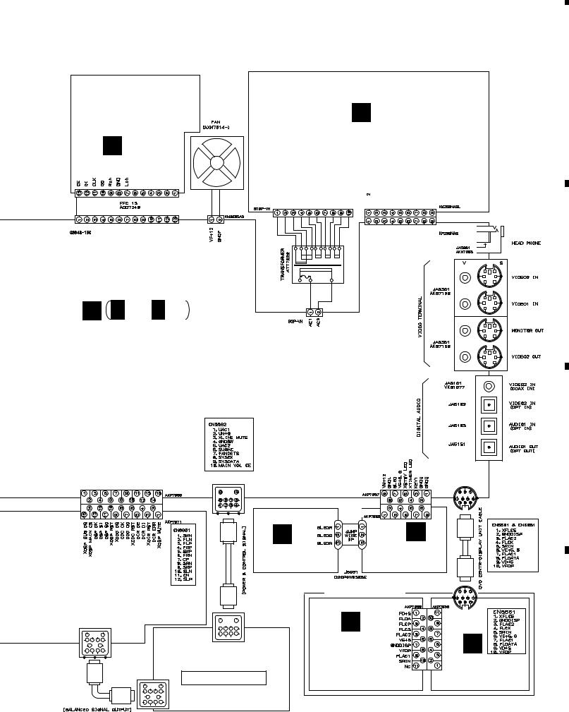
|
5 |
|
6 |
|
7 |
|
8 |
|
|
|
|
XV-DV55
Note : When ordering service parts, be sure to refer to "EXPLODED VIEWS and PARTS LIST" or "PCB PARTS LIST".
TUNER MODULE
(AUCXJ, ADXJ/RA, APWXJ: AXQ7228) (AVXJ,AYXJ: AXQ7229)
J
 CN201
CN201
CN5701
E
REGULATOR ASSY (AWU7676)
CN5011

 CN5021
CN3651 |
CN5002 |
|
F F 1/2- F 2/3 |
CN5001 |
MOTHER ASSY (AUCXJ: AWU7674) (ADXJ/RA: AWU7650) (APWXJ: AWU7651) (AVXJ,AYXJ: AWU7648)
|
CN5503 |
CN5592 |
|
CN5501 |
|
|
AKP7134 |
|
|
||
|
|
|
|
|
|
|
CN3701 |
|
|
CN5621 |
|
|
M |
J5931 |
N |
||
|
|
|
J5931 |
||
|
|
|
|
|
|
DSP ASSY |
|
BLED ASSY |
KEYB ASSY |
||
|
(AWU7680) |
|
(AWU7675) |
||
(AUCXJ: AWU7640) |
|
|
|
|
|
(ADXJ/RA: AWU7640) |
|
|
DISPLAY UINT |
||
(APWXJ: AWU7640) |
|
|
|
CN5661 |
|
(AVXJ, AYXJ: AWU7669) |
|
|
K |
|
|
CN8901 |
CN3002 |
|
|
|
|
|
|
FLDP ASSY |
|
||
AKP7131 |
AKP7134 |
|
|
|
|
|
|
|
|
|
|
|
SUBWOOFER |
|
(AWU7678) |
|
|
|
|
|
|
||
|
S-DV55SW-K/Q |
|
|
|
|
|
CN3001 |
|
|
|
|
|
AKP7131 |
|
|
|
|
CN5652
CN5591
AKP7128
CN5651
AKP7128
L
CNB ASSY (AWU7679)
15
A
B
C
D
|
5 |
|
6 |
|
7 |
|
8 |
|
|
|
|
|
|
||||
|
|
|
|
|
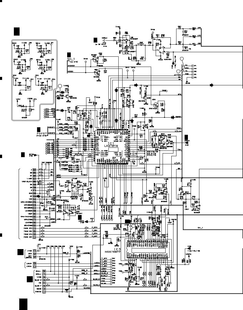
A
B
C
D
1 |
|
2 |
|
|
|
XV-DV55
3.3 DVDM ASSY (1/3)
D 1/3 DVDM ASSY (AWX7724)
D 2/3 
D 2/3
1
D 2/3 |
|
|
(F) |
D 2/3 |
(T) |
(T) |
|
|
(T) |
CN4 |
(T) |
|
|
DKN1193(T) |
|
(F) |
|
(F) |
|
(F) |
|
(F) |
2SC4081 |
ASSY |
|
(T) |
|
PICKUP |
D 2/3 |
|
(F) |
(F) |
(F) |
(F) |
(T) |
(T) |
(T) |
(T) |
CN1
S3B-PH-SM3
A
CN101
LOADING MOTOR ASSY |
CN2 |
|
S2B-PH-SM3 |
B |
(S) |
(S) |
|
||
CN202 |
(S) |
(S) |
CN3
VKN1763
16 D 1/3
3 |
|
4 |
|
|
|
|
|
1/2 |
|
|
2 |
|
|
CHECKER CHIP |
|
|
4 |
|
(DVD) |
(DVD) |
(DVD) |
|
|
|
|
(CD) |
(DVD) |
(CD) |
(F) |
|
(F) |
D 2/3
(F)
RF IC
(T) |
(T) |
2/3 |
(S) |
D |
|

 7
7
(S)
(S)
SPDL & FTS DRIVER
(F) (F) |
(T) (T) |
(F)
(T)
|
1 |
|
2 |
|
3 |
|
4 |
|
|
|
|
|
|
||||
|
|
|
|
|
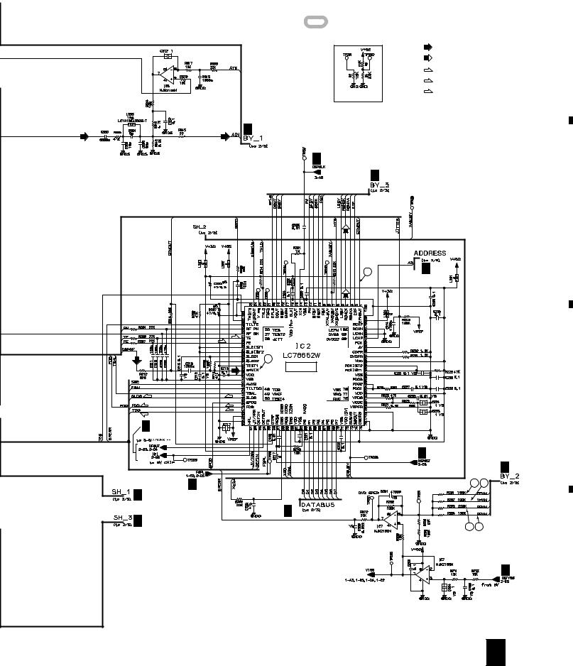
|
5 |
|
6 |
|
7 |
|
8 |
|
|
|
|
|
|
XV-DV55
: The power supply is shown with the marked box.
A
|
|
|
: RF SIGNAL ROUTE |
|
|
|
: ROM DATA SIGNAL ROUTE |
|
|
|
(F) |
|
2/2 |
|
: FOCUS SERVO LOOP LINE |
|
|
(T) |
|
|
|
|
: TRACKING SERVO LOOP LINE |
|
|
|
(S) |
|
|
LANDMARK |
: SLIDER SERVO LOOP LINE |
|
|
for CHECKER |
|
(DVD) |
(DVD) |
D 2/3 |
|
D 3/3
D 2/3
B
6 |
D 2/3 |
(CD)
(T)
(F)
|
(CD) |
5 |
|
DSP IC |
|
(S) |
(S) |
C |
(F) |
(F) |
|
(T) |
(T) |
|
|
|
D 2/3 |
|
|
D 2/3 |
|
D 2/3 |
D 2/3 |
8 9 |
D 2/3 |
|
|
D 2/3 |
D 2/3 |
|
2/2 |
10 11 |
|
|
||
|
|
|
|
1/2 |
D 2/3 |
|
|
D
D 1/3 17
|
5 |
|
6 |
|
7 |
|
8 |
|
|
|
|
|
|
||||
|
|
|
|
|
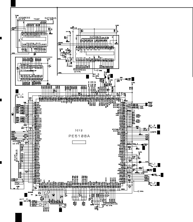
|
1 |
|
2 |
|
3 |
|
4 |
|
|
|
|
|
|
XV-DV55
3.4 DVDM ASSY (2/3)
D 2/3 DVDM ASSY (AWX7724)
A
WORK SRAM (1M)
KM68V1000CLT-7L
AWY7005 FLASH MEMORY (4M)
B
D 3/3
4M DRAM
D 3/3 |
D 1/3 |
|
D 3/3 |
D 1/3
C
BY CHIP
D 1/3
D 1/3

 D 1/3
D 1/3
(DVD)
D 1/3
D 3/3
D 1/3
D 1/3
D
D 3/3 

D 3/3
D 1/3
18 D 2/3
|
1 |
|
2 |
|
3 |
|
4 |
|
|
|
|
|
|
||||
|
|
|
|
|
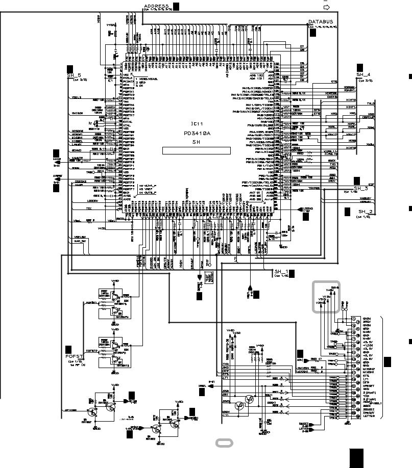
|
5 |
|
6 |
|
7 |
|
8 |
|
|
|
|
|
|
XV-DV55
 : RF SIGNAL ROUTE

 : ROM DATA SIGNAL ROUTE
D 1/3, 3/3 |
: AUDIO SIGNAL ROUTE |
|
A |
|
|
|
D 1/3, 3/3 |
|
|
|
D 3/3 |
|
D 3/3 |
|
|
|
|
|
|
|
B |
D 3/3 |
|
SYSTEM CONTROL CPU |
|
|
|
|
|
|
|
|
|
D 3/3 |
|
|
D 1/3 |
|
|
|
|
|
|
|
|
|
|
|
D 1/3 |
|
|
|
|
|
D 1/3 |
|
|
|
|
|
D 1/3 |
|
C |
|
|
D 1/3 |
D 3/3 |
|
|
|
|
|
CN5 |
|
|
|
|
|
VKN1626 |
|
|
|
D 1/3 |
|
D 3/3 |
|
|
|
|
|
|
F 2/3 |
|
|
|
|
|
|
|
|
|
|
|
|
CN8502 |
|
D 1/3 |
D 3/3 |
Q3 |
|
|
|
|
|
|
||
|
|
Q3 |
|
|
|
|
|
|
|
|
|
|
|
D 1/3 |
RN1911 |
|
D |
|
|
|
|
||
|
|
|
|
|
|
|
D 1/3 |
|
|
|
|
|
|
|
: The power supply is shown with the marked box. |
||
|
|
|
D |
2/3 |
19 |
|
|
|
|
|
|
|
5 |
|
6 |
|
7 |
|
8 |
|
|
|
|
|
|
||||
|
|
|
|
|
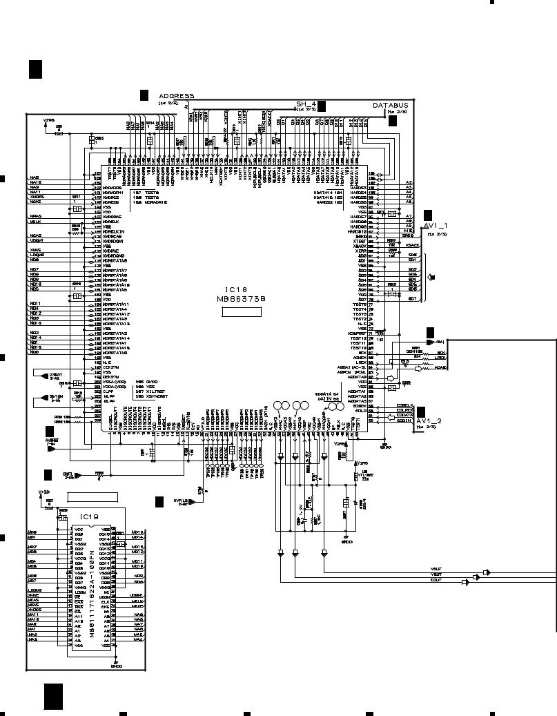
|
1 |
|
2 |
|
3 |
|
4 |
|
|
|
|
XV-DV55
3.5 DVDM ASSY (3/3) |
|
|
|
|
||
D 3/3 DVDM ASSY (AWX7724) |
|
|
|
|||
A |
|
D 2/3 |
|
|
|
|
|
|
|
|
D 2/3 |
|
|
|
|
|
|
|
|
|
|
|
|
|
|
|
D 2/3 |
|
|
|
|
|
|
D 2/3 |
B |
|
|
|
|
|
|
|
|
|
AV-1 |
|
|
|
|
|
|
|
|
|
D 2/3 |
|
|
|
14 17 |
13 16 |
12 15 |
D 2/3 |
|
|
|
|
|
|
|
|
D 2/3 |
|
|
|
(VCB) |
|
C |
|
|
(C) |
(Y) |
|
|
|
|
|
|
|
|
|
|
D 2/3 |
|
|
|
|
|
|
16M SDRAM |
D 2/3 |
|
|
|
|
|
|
|
|
|
|
|
|
|
|
(C) |
(Y) |
(VCB) |
|
D |
|
|
|
|
|
|
20 |
D 3/3 |
|
|
|
|
|
|
1 |
|
2 |
3 |
|
4 |
(VCB) |
(Y) |
(C) |
5 |
6 |
7 |
|
8 |
|
|
|
|
XV-DV55 |
||
D 2/3 |
|
|
: AUDIO SIGNAL ROUTE |
|
|
|
|
|
: ROM DATA SIGNAL ROUTE |
|
|
|
|
(VCB) |
: V/CB SIGNAL ROUTE |
|
|
|
|
(Y) |
|
|
|
|
|
: Y SIGNAL ROUTE |
|
|
|
|
|
(C) |
|
|
|
|
|
: C SIGNAL ROUTE |
|
|
|
|
|
|
|
|
|
|
|
D 2/3 |
|
|
|
|
CLOCK |
D 2/3 |
|
|
|
|
GENERATOR |
|
|
|
|
|
|
D 1/3 |
|
|
|
|
|
D 2/3 |
|
|
|
|
D 2/3 |
|
|
|
|
|
(VCB) |
|
|
|
|
|
(VCB) |
|
|
|
|
|
(Y) |
|
|
|
|
|
(Y) |
|
CN15 |
|
|
|
|
|
|
|
|
|
|
|
VKN1763 |
|
|
|
|
(VCB) |
|
|
|
|
(C) |
(C) |
|
|
|
|
(C) |
(Y) |
|
|
|
|
|
|
|
|
|
(VCB) |
|
|
|
|
|
(Y) |
|
|
|
F 2/3 |
|
(C) |
|
|
|
||
|
|
|
|
CN8501 |
|
|
|
|
D |
3/3 |
21 |
|
|
|
|
|
|
5 |
6 |
7 |
|
8 |
|
A
B
C
D
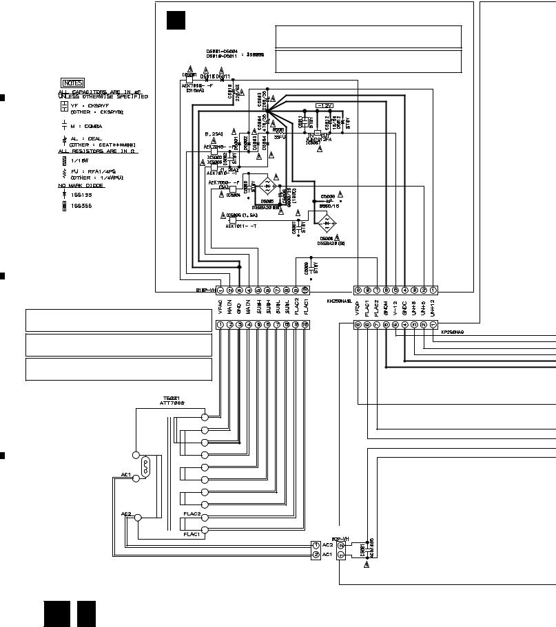
|
1 |
|
2 |
|
3 |
|
4 |
|
|
|
|
|
|
XV-DV55
3.6 REGULATOR and MOTHER ASSYS (1/3)
A
E |
REGULATOR ASSY |
|
|
(AWU7676) |
CAUTION : FOR CONTINUED PROTECTION AGAINST RISK OF FIRE. |
|
|
REPLACE WITH SAME TYPE NO. AEK7059 MFD. BY |
|
|
LITTELFUSE INC. FOR IC5001. |
|
|
CAUTION : FOR CONTINUED PROTECTION AGAINST RISK OF FIRE. |
|
|
REPLACE WITH SAME TYPE NO. AEK7048 MFD. BY |
|
|
LITTELFUSE INC. FOR IC5002. |
B
CN5011
CN5021
CAUTION : FOR CONTINUED PROTECTION AGAINST RISK OF FIRE.
REPLACE WITH SAME TYPE NO. AEK7010 MFD. BY
LITTELFUSE INC. FOR IC5003.
CAUTION : FOR CONTINUED PROTECTION AGAINST RISK OF FIRE.
REPLACE WITH SAME TYPE NO. AEK7050 MFD. BY
LITTELFUSE INC. FOR IC5004.
CAUTION : FOR CONTINUED PROTECTION AGAINST RISK OF FIRE.
C REPLACE WITH SAME TYPE NO. AEK7011 MFD. BY
LITTELFUSE INC. FOR IC5005.
CN5001
D
CN5002 |
22 E 
 F 1/3
F 1/3
|
1 |
|
2 |
|
3 |
|
4 |
|
|
|
|
|
|
||||
|
|
|
|
|
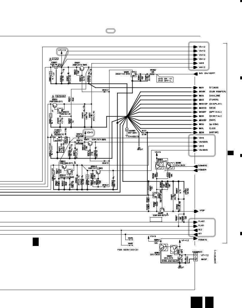
|
5 |
|
6 |
|
7 |
|
|
|
|
|
: The power supply is shown with the marked box.
VFDP
F 1/3 MOTHER ASSY
(AUCXJ: AWU7674) |
CN3651 |
|
(ADXJ/RA: AWU7650) |
||
|
||
(APWXJ:AWU7651) |
|
|
(AVXJ,AYXJ: AWU7648) |
|
8
XV-DV55
A
B
F 2/3
C
TO. FAN
D
E 
 F 1/3 23
|
5 |
|
6 |
|
7 |
|
8 |
|
|
|
|
|
|
||||
|
|
|
|
|

|
1 |
|
|
2 |
|
|
|
|
3 |
|
|
|
4 |
|
|
||
|
|
|
|
|
|||||||||||||
|
XV-DV55 |
|
|
|
|
|
|
|
|
|
|
|
|
||||
|
3.7 MOTHER ASSY (2/3) |
|
|
|
|
|
|
|
|
|
|
|
|
||||
|
|
|
2/3 MOTHER ASSY |
|
|
|
|
|
|
|
|
|
|
||||
|
|
F |
|
|
|
CN5621 |
|
|
|
1/3 |
|
|
|||||
|
|
|
|
N |
|
|
F |
|
|
||||||||
|
|
|
(AUCXJ: AWU7674) |
|
|
|
|
|
|
|
|
|
|
|
|
||
|
|
|
|
|
|
|
|
|
|
|
|
|
|
|
|||
A |
(ADXJ/RA: AWU7650) |
|
|
|
(APWXJ:AWU7651) |
|
(AVXJ,AYXJ: AWU7648) |
|
CN5501 |
|
CN8501 |
D 3/3 CN15
B
F 1/3
C
D 1/3 CN5
CN8502
|
1/3 |
|
|
|
|
|
|
||||
|
|
||||
|
|
||||
D |
F |
|
|
|
|
|
|||||
|
|
|
|
|
|
|
|
|
|
|
|
(DVD)
(DVD) |
(DVD) |
(DVD)
|
R5592 |
R5594 |
R5597 |
|
AUCXJ |
Not used |
Not used Not used |
||
ADXJ/RA |
47k |
Not used Not used |
||
APWXJ |
Not used |
Not used |
47k |
|
AVXJ |
Not used |
47k |
Not used |
|
AYXJ |
||||
|
|
|
||
24 F 2/3 |
N CN5651 |
|
|
1 |
|
2 |
|
3 |
|
4 |
|
|
|
|
|
|
||||
|
|
|
|
|
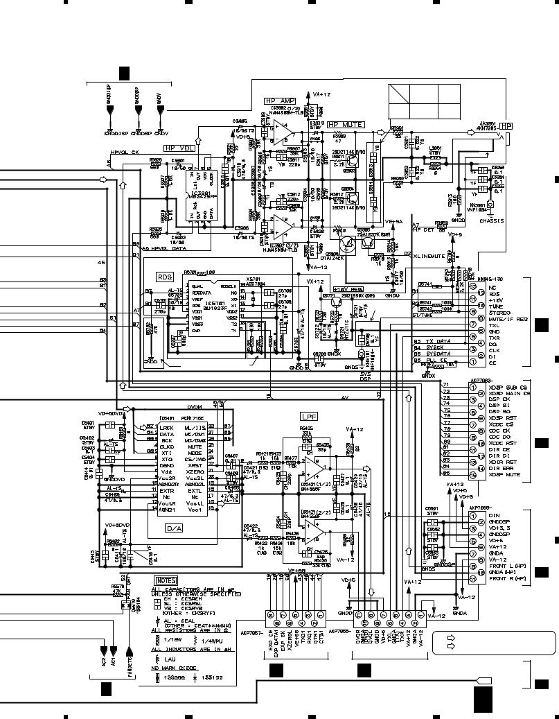
5 |
6 |
7 |
|
|
|
8 |
|
|
|
|
|
|
|
|
XV-DV55 |
|
|
||
F 1/3 |
|
|
|
|
|
|
|
|
|
|
|
|
AUCXJ |
AVXJ |
|
|
|
|
A |
|
|
|
ADXJ/RA |
|
|
|
|
|
|
|
|
|
APWXJ |
AYXJ |
|
|
|
|
|
|
|
C3913 |
1000p |
10000p |
|
|
|
|
|
|
|
C3914 |
|
|
|
|
|||
|
|
|
|
|
|
|
|
|
|
(DVD) |
|
|
|
|
|
|
|
|
|
|
|
|
|
|
CN5701 |
|
|
B |
|
|
|
|
|
|
|
|
|
||
|
|
AVXJ, AYXJ |
|
|
|
|
|
CN201 |
|
|
|
only |
|
|
|
|
|
|
|
|
|
|
|
|
|
|
|
|
|
|
|
|
|
|
|
|
|
J |
|
|
except AUXJ, AVXJ |
|
|
|
|
|
|
|
|
|
|
|
|
|
CN5503 |
|
|
|
|
(DVD) |
|
|
|
|
|
|
|
CN3701 |
|
(DVD) |
|
|
|
|
|
|
|
|
|
|
|
|
|
|
|
|
1/2 |
|
|
|
|
|
|
|
|
|
|
|
|
|
|
|
|
|
|
|
|
I |
C |
|
|
|
|
|
|
|
|
|
|
|
|
(DVD) |
|
|
|
|
|
|
|
|
|
|
|
|
CN5504 |
|
|
|
|
|
(DVD) |
|
|
|
|
|
|
|
|
|
|
|
|
|
|
|
|
1/2 CN3702 |
|
|
|
(DVD) |
|
|
|
|
|
I |
|
|
|
|
|
|
|
|
|
|
|
|
CN5506 |
CN5505 |
|
|
|
|
|
|
D |
|
|
|
|
|
|
|
|
|
|
|
|
|
(DVD) |
: AUDIO SIGNAL ROUTE |
|
|
|||
|
|
|
: DVD AUDIO SIGNAL ROUTE |
|
|||||
|
|
|
|
|
|
||||
|
G CN5204 |
G CN5203 |
8, 9, 10,13,14,15 |
AVPART |
|
3/3 |
|
||
F 1/3 |
|
|
|
|
F |
|
F |
|
|
|
|
|
|
2/3 |
|
|
|||
|
|
|
|
|
|
|
|||
|
|
|
|
|
25 |
|
|
||
|
|
7 |
|
|
|
|
|
||
5 |
6 |
|
|
|
8 |
|
|
|
|
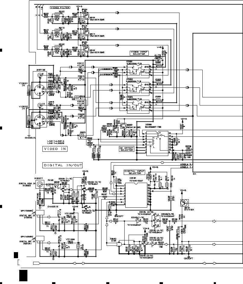
|
1 |
|
2 |
|
3 |
|
4 |
|
|
|
|
|
|
XV-DV55
3.8 MOTHER ASSY (3/3)
A |
|
|
|
(Y) |
|
|
|
|
|
|
(C) |
|
|
|
|
|
|
(V) |
|
|
|
|
(V) |
(V) |
|
|
|
|
JA5301 |
|
|
(V) |
|
|
|
|
|
(V) |
|
|
|
|
|
|
|
(C) |
|
|
|
|
|
|
|
(C) |
|
B |
|
|
|
(C) |
|
|
|
|
|
|
|
|
|
|
|
(C) |
|
|
|
|
|
|
|
|
(Y) |
|
|
|
|
(V) |
|
|
(Y) |
|
|
|
|
|
(Y) |
|
|
|
|
(Y) |
|
|
|
|
|
|
(C) |
|
|
|
|
|
|
VTL1087 |
|
|
|
|
C |
|
|
|
|
(DVD) |
|
|
|
|
|
|
|
|
|
JA5101 |
|
(DVD) |
|
|
|
|
|
VTL1112 |
|
|
|
|
|
|
|
|
|
|
|
|
|
VTL1112 |
|
(D) |
|
|
|
|
|
|
|
|
|
|
JA5102 |
|
|
|
|
|
|
|
(D) |
(D) |
|
|
|
|
|
|
|
|
|
|
|
|
|
(D) |
(D) |
|
(D) |
|
JA5103 |
|
|
|
|
|
D |
|
(D) |
|
|
|
(D) |
|
|
|
|
|
|
|
P |
|
|
|
|
|
|
F 2/3 |
|
|
|
|
|
|
|
AVPART |
8, 9, 10, 13, 14, 15 |
|
|
|
|
|
(DVD) |
(D) |
|
(DVD) |
(D) |
|
|
|
|
||||
26 |
F 3/3 |
|
|
|
|
|
|
1 |
|
2 |
3 |
4 |
|
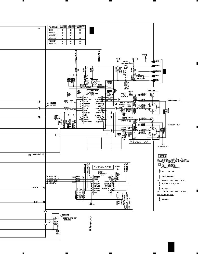
|
5 |
6 |
|
|
7 |
|
|
8 |
|
|
|
|
|
|
|
|
XV-DV55 |
||
|
|
|
F 3/3 MOTHER ASSY |
|
|
|
A |
||
|
|
|
|
(AUCXJ: AWU7674) |
|
|
|||
|
|
|
|
(ADXJ/RA: AWU7650) |
|
|
|||
|
|
|
|
(APWXJ:AWU7651) |
|
|
|||
|
|
|
|
(AVXJ,AYXJ: AWU7648) |
|
|
|||
|
|
|
|
|
|
|
P |
|
|
|
|
|
|
|
|
|
F 2/3 |
|
|
|
|
|
|
|
|
|
JA5351 |
|
|
|
|
|
|
|
|
(V) |
|
|
B |
|
|
|
|
|
|
330p |
|
|
|
|
|
|
|
|
(V) |
|
|
|
|
(V) |
|
|
|
|
|
|
|
|
|
|
|
|
|
|
|
|
|
|
|
|
|
|
|
|
|
330p |
(Y) |
|
|
|
|
|
|
|
(V) |
|
|
|
|
(C) |
|
|
|
|
|
|
|
|
|
|
|
|
|
|
|
|
|
|
|
|
|
|
|
|
(C) |
(C) |
|
|
|
|
|
|
|
|
|
C5376 |
|
|
|
|
|
|
|
(C) |
|
330p |
|
|
|
(Y) |
|
|
|
|
|
|
|
|
|
|
|
|
|
|
(V) |
|
|
||
|
|
|
|
(Y) |
|
|
|
||
|
|
|
|
|
|
|
|
|
|
|
|
|
|
|
|
330p |
|
|
|
|
|
|
|
|
|
330p |
|
|
|
|
|
|
|
(Y) |
|
(Y) |
|
|
|
|
|
|
|
|
|
(C) |
|
|
|
|
|
|
|
|
|
C5382 |
|
|
|
|
|
|
|
AUCXJ |
|
330p |
|
|
|
|
|
|
|
|
|
|
|
|
|
|
|
|
|
ADXJ/RA |
AVXJ |
|
|
|
|
|
|
|
|
APWXJ |
AYXJ |
|
|
|
|
|
|
L5371L5374 |
VTL1087 |
VTL1081 |
|
|
|
|
|
|
|
L5377L5380 |
|
|
|
|
|||
|
|
|
|
|
|
|
|
||
(DVD) |
|
|
|
|
|
|
|
|
C |
|
|
|
|
|
|
|
|
|
|
(DVD) |
|
JA5151 |
|
|
|
|
|
|
|
|
(D) |
: AUDIO SIGNAL ROUTE (DIGITAL) |
|
|
|
|
|||
|
|
|
|
|
|
||||
|
|
(DVD) |
|
|
|
|
|||
|
|
: DVD AUDIO SIGNAL ROUTE |
|
|
|
|
|||
|
|
(V) |
|
|
|
D |
|||
(D) |
(D) |
: VIDEO SIGNAL ROUTE |
|
|
|
||||
|
(Y) |
|
|
|
|
||||
|
|
: Y SIGNAL ROUTE |
|
|
|
|
|||
|
|
(C) |
|
|
|
|
|||
|
|
: C SIGNAL ROUTE |
|
|
|
|
|||
|
|
|
|
|
|
|
|||
|
|
|
|
|
|
|
F |
3/3 |
27 |
|
|
|
|
|
7 |
|
|
||
|
5 |
6 |
|
|
|
|
8 |
|
|
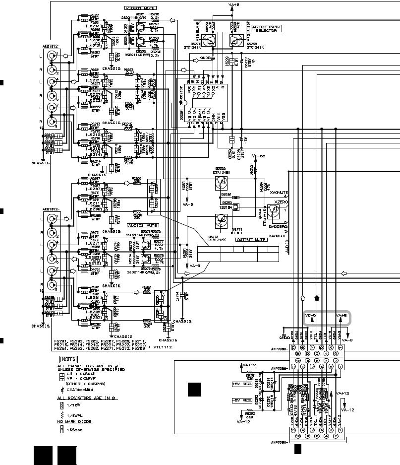
|
1 |
|
2 |
|
|
XV-DV55
3.9 AJKB and TRADE ASSYS
A
JA5201
VIDEO1 OUT
VIDEO1 IN
VIDEO2 IN
B
JA5202
AUDIO2 IN
AUDIO1 OUT
C
AUDIO1 IN
D
28 G
 H
H
|
3 |
|
4 |
|
|
|
|
(DVD)
(TA)
 AUCXJ ADXJ APWXJ AVXJ AYXJ
C5203, C5204 |
100p |
1000p |
|
C5209, C5210 |
|||
|
|
(DVD) |
(TA) |
CN5201
CN5202
G
TRADE ASSY
(AWU7677)
CN5203
F 2/3 CN5505
|
1 |
|
2 |
|
3 |
|
4 |
|
|
|
|
|
|
||||
|
|
|
|
|
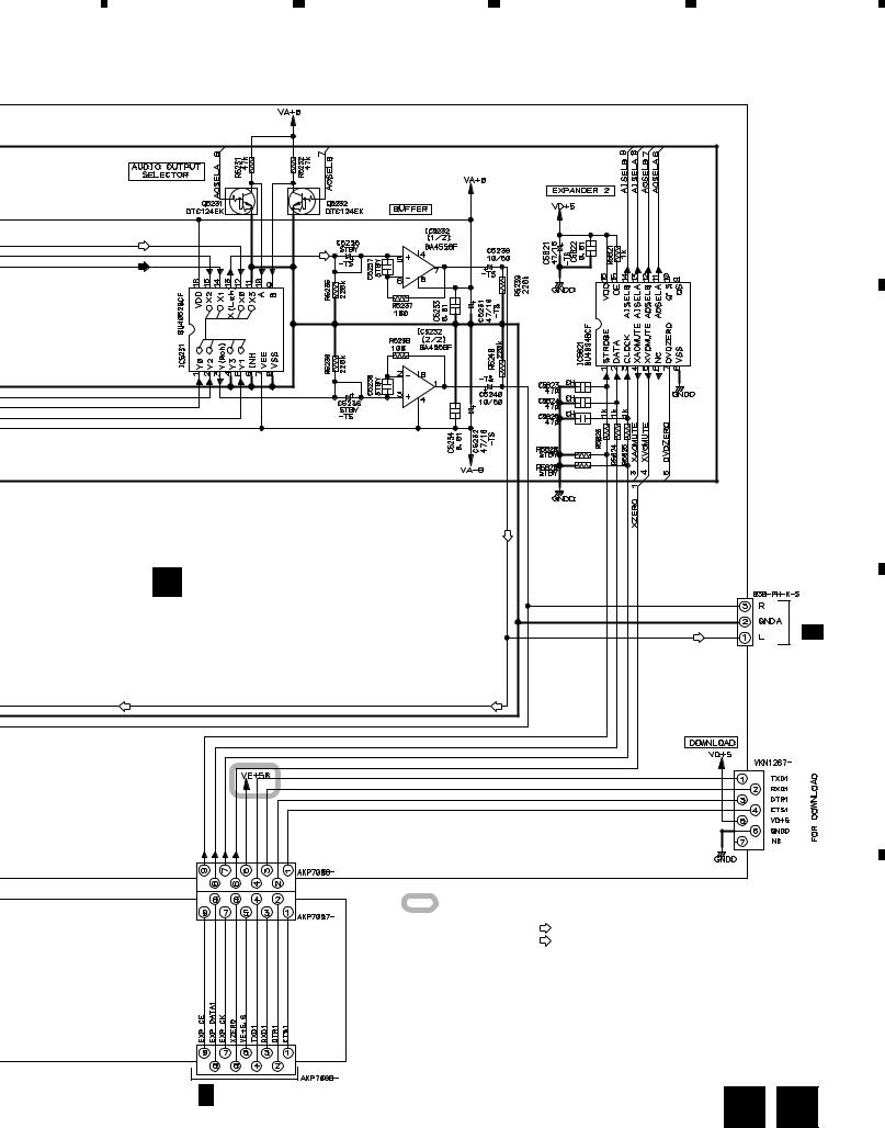
5 |
6 |
7 |
8 |
|
|
|
|
XV-DV55 |
|
|
|
|
|
A |
(DVD) |
|
|
|
|
(TA) |
|
|
|
|
|
|
|
|
B |
H |
|
|
CN5207 |
CN3703 |
|
|
|
||
AJKB ASSY |
|
|
|
1/2 |
(AUCXJ, ADXJ/RA, APWXJ: AWU7641) |
|
|
I |
|
|
|
|
||
(AVXJ,AYXJ: AWU7670) |
|
|
|
|
C
CN5507
CN5206
CN5205 |
: The power supply is shown with the marked box. |
|
: AUDIO SIGNAL ROUTE
(DVD) |
: DVD AUDIO SIGNAL ROUTE |
|
(TX) : TUNER AUDIO SIGNAL ROUTE
CN5204
F 2/3 CN5506
D
G
 H 29
H 29
|
5 |
|
6 |
|
7 |
|
8 |
|
|
|
|
|
|
||||
|
|
|
|
|
 Loading...