


AUDIO/VIDEO
MULTI-CHANNEL RECEIVER
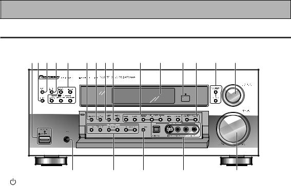
VSX-35TX
Operating Instructions
Thank you for buying this Pioneer product.
Please read through these operating instructions so you will know how to operate your model properly.
After you have finished reading the instructions, put them away in a safe place for future reference.
IMPORTANT NOTICE
The serial number for this equipment is located on the rear panel. Please write this serial number on your enclosed warranty card and keep it in a secure area. This is for your security.
WARNING: TO PREVENT FIRE OR SHOCK
HAZARD, DO NOT EXPOSE THIS APPLIANCE TO RAIN OR MOISTURE.
THE STANDBY/ON BUTTON IS SECONDARY CONNECTED AND THEREFORE DOES NOT SEPARATE THE UNIT FROM MAINS POWER IN STANDBY POSITION.
IMPORTANT
The lightning flash with arrowhead symbol, within an equilateral triangle, is intended to alert the user to the presence of uninsulated "dangerous voltage" within the product's enclosure that may be of sufficient magnitude to constitute a risk of electric shock to persons.
CAUTION
RISK OF ELECTRIC SHOCK
DO NOT OPEN
CAUTION:
TO PREVENT THE RISK OF ELECTRIC SHOCK, DO NOT REMOVE COVER (OR BACK). NO USER-SERVICEABLE PARTS INSIDE. REFER SERVICING TO QUALIFIED SERVICE PERSONNEL.
The exclamation point within an equilateral triangle is intended to alert the user to the presence of important operating and maintenance (servicing) instructions in the literature accompanying the appliance.
NOTE: This equipment has been tested and found to comply with the limits for a Class B digital device, pursuant to Part 15 of the FCC Rules. These limits are designed to provide reasonable protection against harmful interference in a residential installation. This equipment generates, uses, and can radiate radio frequency energy and, if not installed and used in accordance with the instructions, may cause harmful interference to radio communications. However, there is no guarantee that interference will not occur in a particular installation. If this equipment does cause harmful interference to radio or television reception, which can be determined by turning the equipment off and on, the user is encouraged to try to correct the interference by one or more of the following measures:
–Reorient or relocate the receiving antenna.
–Increase the separation between the equipment and receiver.
–Connect the equipment into an outlet on a circuit different from that to which the receiver is connected.
–Consult the dealer or an experienced radio/TV technician for help.
Information to User
Alteration or modifications carried out without appropriate authorization may invalidate the user's right to operate the equipment.
[For Canadian model]
This Class B digital apparatus complies with Canadian ICES-003.
[Pour le modèle Canadien]
Cet appareil numérique de la classe B est conforme à la norme NMB-003 du Canada.
[For Canadian model]
CAUTION: TO PREVENT ELECTRIC SHOCK DO NOT USE THIS (POLARIZED) PLUG WITH AN EXTENSION CORD, RECEPTACLE OR OTHER OUTLET UNLESS THE BLADES CAN BE FULLY INSERTED TO PREVENT BLADE EXPOSURE.
ATTENTION: POUR PREVENIR LES CHOCS ELECTRIQUES NE PAS UTILISER CETTE FICHE POLARISEE AVEC UN PROLONGATEUR, UNE PRISE DE COURANT OU UNE AUTRE SORTIE DE COURANT, SAUF SI LES LAMES PEUVENT ETRE INSERESS A FOND SANS EN LAISSER AUCUNE PARTIE A DECOUVERT.
ATTENTION: AFIN DE PREVENIR TOUS
RISQUES DE CHOC ELECTRIQUE OU DE DEBUT D'ENCENDIE, NE PAS EXPOSER CET APPAREIL A L'HUMIDITE OU A LA PLUIE.
LE BOUTON STANDBY/ON EST RACCORDE SECONDAIREMENT ET PAR CONSEQUENT NE SEPARE PAS L’APPAREIL DE L’ALIMENTATION SECTEUR SUR LA POSITION D’ATTENTE.
2
IMPORTANT SAFETY INSTRUCTIONS
READ INSTRUCTIONS — All the safety |
GROUNDING OR POLARIZATION |
OBJECT AND LIQUID ENTRY — Never |
||||||||||||
and operating instructions should be |
÷ If this product is equipped with a |
push objects of any kind into this product |
||||||||||||
read before the product is operated. |
polarized alternating current line plug (a |
through openings as they may touch |
||||||||||||
RETAIN INSTRUCTIONS —The safety and |
plug having one blade wider than the |
dangerous voltage points or short-out |
||||||||||||
operatinginstructionsshouldberetained |
other), it will fit into the outlet only one |
parts that could result in a fire or electric |
||||||||||||
for future reference. |
|
|
|
way. This is a safety feature. If you are |
shock. Never spill liquid of any kind on |
|||||||||
HEED WARNINGS — All warnings on the |
unable to insert the plug fully into the |
the product. |
|
|
|
|
||||||||
product and in the operating instructions |
outlet, try reversing the plug. If the plug |
SERVICING — Do not attempt to service |
||||||||||||
should be adhered to. |
|
|
should still fail to fit, contact your |
this product yourself as opening or |
||||||||||
FOLLOW INSTRUCTIONS — All operating |
electrician to replace your obsolete |
removing covers may expose you to |
||||||||||||
and use instructions should be followed. |
outlet. Do not defeat the safety purpose |
dangerous voltage or other hazards. |
||||||||||||
CLEANING — Unplug this product from the |
of the polarized plug. |
|
|
Refer all servicing to qualified service |
||||||||||
wall outlet before cleaning. The product |
÷ If this product is equipped with a three- |
personnel. |
|
|
|
|
||||||||
should be cleaned only with a polishing |
wire grounding type plug, a plug having |
DAMAGE REQUIRING SERVICE — Unplug |
||||||||||||
cloth or a soft dry cloth. Never clean |
a third (grounding) pin, it will only fit into |
this product from the wall outlet and |
||||||||||||
with furniture wax, benzine, insecticides |
a grounding type power outlet. This is a |
refer servicing to qualified service |
||||||||||||
or other volatile liquids since they may |
safety feature. If you are unable to insert |
personnel |
under |
the |
following |
|||||||||
corrode the cabinet. |
|
|
|
the plug into the outlet, contact your |
conditions: |
|
|
|
|
|||||
ATTACHMENTS— Do notuse attachments |
electrician to replace your obsolete |
÷ When the power-supply cord or plug is |
||||||||||||
not recommended by the product |
outlet. Do not defeat the safety purpose |
damaged. |
|
|
|
|
||||||||
manufacturer as they may cause |
of the grounding type plug. |
|
÷ If liquid has been spilled, or objects |
|||||||||||
hazards. |
|
|
|
|
|
POWER-CORD PROTECTION — Power- |
have fallen into the product. |
|
||||||
WATER AND MOISTURE — Do not use |
supply cords should be routed so that |
÷ If the product has been exposed to rain |
||||||||||||
this product near water — for example, |
they are not likely to be walked on or |
or water. |
|
|
|
|
||||||||
near a bathtub, wash bowl, kitchen sink, |
pinched by items placed upon or against |
÷ If the product does not operate normally |
||||||||||||
or laundry tub; in a wet basement; or |
them,payingparticularattentiontocords |
by following the operating instructions. |
||||||||||||
near a swimming pool; and the like. |
at plugs, convenience receptacles, and |
Adjust only those controls that are |
||||||||||||
ACCESSORIES — Do not place this product |
the point where they exit from the |
covered by the operating instructions |
||||||||||||
on an unstable cart, stand, tripod, |
product. |
|
|
as an improper adjustment of other |
||||||||||
bracket, or table. The product may fall, |
OUTDOOR ANTENNA GROUNDING — If |
controls may result in damage and will |
||||||||||||
causing serious injury to a child or adult, |
an outside antenna or cable system is |
often require extensive work by a |
||||||||||||
and serious damage to the product. Use |
connected to the product, be sure the |
qualified technician to restore the |
||||||||||||
only with a cart, stand, tripod, bracket, |
antenna or cable system is grounded so |
product to its normal operation. |
||||||||||||
or table recommended by the |
as to provide some protection against |
÷ If the product has been dropped or |
||||||||||||
manufacturer, or sold with the product. |
voltage surges and built-up static |
damaged in any way. |
|
|
|
|||||||||
Any mounting of the product should |
charges. Article 810 of the National |
÷ When the product exhibits a distinct |
||||||||||||
follow the manufacturer’s instructions, |
ElectricalCode,ANSI/NFPA70,provides |
change in performance — this indicates |
||||||||||||
and should use a mounting accessory |
information with regard to proper |
a need for service. |
|
|
|
|||||||||
recommended by the manufacturer. |
grounding of the mast and supporting |
REPLACEMENT PARTS |
— |
When |
||||||||||
CART — A product and cart combination |
structure, grounding of the lead-in wire |
replacement parts are required, be sure |
||||||||||||
should be moved with care. Quick stops, |
to an antenna discharge unit, size of |
the service technician has used |
||||||||||||
excessive force, and uneven surfaces |
grounding conductors, |
location of |
replacement parts specified by the |
|||||||||||
may cause the product and cart |
antenna-discharge unit, connection to |
manufacturer or have the same |
||||||||||||
combination to overturn. |
|
|
grounding electrodes, andrequirements |
characteristics as the original part. |
||||||||||
|
|
|
|
|
|
for the grounding electrode. See Figure |
Unauthorized substitutions may result |
|||||||
|
|
|
|
|
|
A. |
|
|
in fire, electric shock, or other hazards. |
|||||
|
|
|
|
|
|
LIGHTNING — For added protection for this |
SAFETY CHECK — Upon completion of any |
|||||||
|
|
|
|
|
|
productduringalightningstorm,orwhen |
service or repairs to this product, ask |
|||||||
|
|
|
|
|
|
it is left unattended and unused for long |
the service technician to perform safety |
|||||||
|
|
|
|
|
|
periods of time, unplug it from the wall |
checks to determine that the product is |
|||||||
|
|
|
|
|
|
outlet and disconnect the antenna or |
in proper operating condition. |
|
||||||
|
|
|
|
|
|
cable system. This will prevent damage |
WALL OR CEILING MOUNTING — The |
|||||||
|
|
|
|
|
|
to the product due to lightning and |
product should not be mounted to a |
|||||||
|
|
|
|
|
|
power-line surges. |
|
|
wall or ceiling. |
|
|
|
||
|
|
|
|
|
|
POWER LINES — An outside antenna |
HEAT — The product should be situated |
|||||||
VENTILATION — Slots and openings in the |
system should not be located in the |
away from |
heat sources |
such as |
||||||||||
vicinity of overhead power lines or other |
radiators, heat registers, stoves, or other |
|||||||||||||
cabinet are provided for ventilation and |
||||||||||||||
electric light or power circuits, or where |
products (including |
amplifiers) that |
||||||||||||
to ensure |
reliable |
operation of the |
||||||||||||
itcanfallintosuchpowerlinesorcircuits. |
produce heat. |
|
|
|
||||||||||
product and |
to |
protect |
it |
from |
|
|
|
|||||||
When installing an outside |
antenna |
|
|
|
|
|
||||||||
overheating, and these openings must |
|
|
|
|
|
|||||||||
system, extreme care should be taken |
|
|
|
|
|
|||||||||
not be blocked or covered. The openings |
to keep from touching such power lines |
|
|
|
|
|
||||||||
should never be blocked by placing the |
|
|
|
|
|
|||||||||
or circuits as contact with them might |
|
|
|
|
|
|||||||||
product on a bed, sofa, rug, or other |
|
|
|
|
|
|||||||||
be fatal. |
|
|
|
|
|
|
|
|||||||
similar surface. This product should not |
OVERLOADING — Do not overload wall |
|
|
|
|
|
||||||||
be placed in a built-in installation such |
|
|
|
|
|
|||||||||
outlets, extension cords, |
or |
integral |
|
|
|
|
|
|||||||
as a bookcase or rack unless proper |
|
|
|
|
|
|||||||||
convenience receptacles |
as |
this can |
|
|
|
|
|
|||||||
ventilation |
is |
provided |
or |
the |
result in a risk of fire or electric shock. |
|
ANTENNA |
|
|
|||||
manufacturer’s instructions have been |
|
|
|
|||||||||||
|
|
|
|
|
|
|||||||||
adhered to. |
|
|
|
|
|
|
|
|
|
LEAD IN |
|
|
||
POWER SOURCES — This product should |
|
|
|
|
WIRE |
|
|
|
||||||
be operated only from the type of power |
|
|
GROUND |
|
|
|
|
|
||||||
source indicated on the marking label. If |
|
|
|
|
|
|
|
|||||||
|
|
CLAMP |
|
|
|
|
|
|||||||
you are not sure of the type of power |
|
|
|
|
|
|
|
|||||||
|
|
|
|
|
|
|
|
|||||||
supply to your home, consult your |
|
|
|
|
ANTENNA |
|
|
|||||||
product dealer or local power company. |
|
|
|
|
DISCHARGE UNIT |
|||||||||
LOCATION – The appliance should be in- |
|
|
|
|
(NEC SECTION 810-20) |
|||||||||
stalled in a stable location. |
|
|
|
|
|
|
|
|
|
|
||||
NONUSE PERIODS – The power cord of |
ELECTRIC |
|
GROUNDING CONDUCTORS |
|||||||||||
the appliance should be unplugged from |
|
|||||||||||||
the outlet when left un-used for a long |
SERVICE |
|
|
(NEC SECTION 810-21) |
||||||||||
period of time. |
|
|
|
|
EQUIPMENT |
GROUND CLAMPS |
|
|
||||||
|
|
|
|
|
|
|
|
|
|
|
||||
|
|
|
|
|
|
|
|
|
POWER SERVICE GROUNDING |
|||||
|
|
|
|
|
|
Fig. A |
ELECTRODE SYSTEM |
|
|
|||||
|
|
|
|
|
|
|
|
|
(NEC ART 250, PART H) |
|
||||
NEC — NATIONAL ELECTRICAL CODE
3
Quick Start Guide
This is a quick guide to setting up your new receiver so you can get home theater surround sound. For more details on any of the information presented here check the main section of the manual.
Before making or changing the connections, switch off the power and disconnect the power cord from the AC wall outlet.
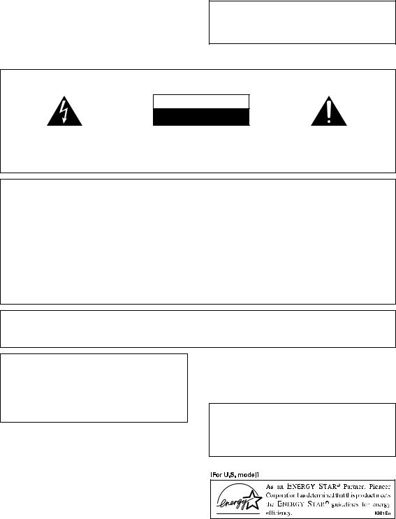
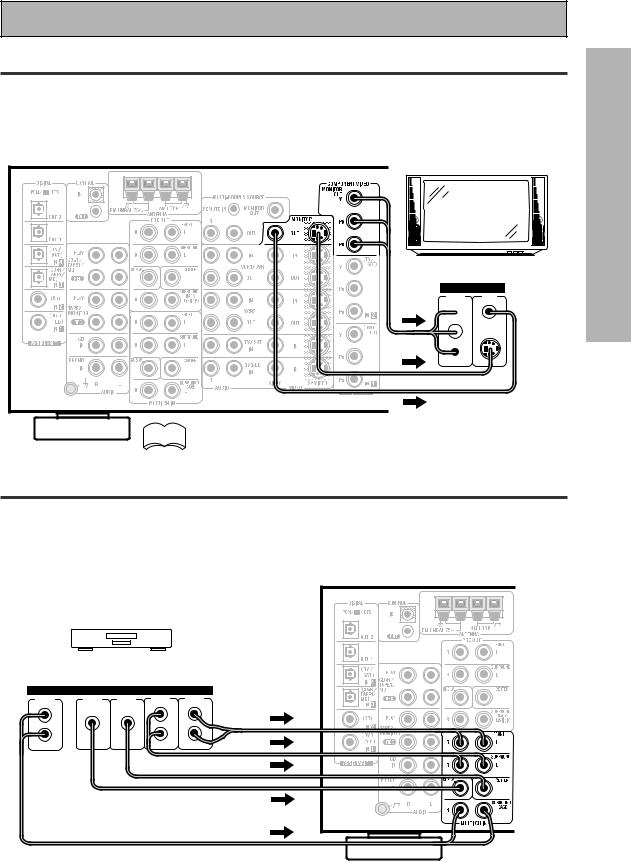
1 Hooking Up Your DVD Player & TV
In order to use Dolby Digital/DTS soundtracks which are at the heart of home theater you need to hook up your DVD player with digital audio connections. You can do this by either a coaxial or an optical connection, you don’t need to do both. The quality of these two types of connections is the same but since some digital components only have one type of digital terminal you need to figure out which yours has and hook it up to the appropriate terminal on the receiver. In order to do this you will need the proper cable. For coaxial connections you can use a regular RCA stereo cord or the specially-made coaxial cords, they have the same type of plugs. For optical connections you will need a special optical cord which you can buy at your local stereo store. Also hook up the video connection of your DVD player, the analog audio (for recording the audio on DVDs, use regular RCA stereo cords), and your TV (it's easiest to use a regular composite RCA video cords) as shown below. It is important that you hook up your TV (or monitor) in order to see a video image as well as the on screen displays (OSDs) shown by this receiver (for more on p. 16-17). We also recommend hooking up your all your digital components to analog audio jacks. For this you can use regular RCA stereo cords.
Coaxial Digital Connection
If your DVD player has a coaxial terminal (not a PCM-only output) for the audio out hook it up using this terminal. Follow the diagram below. This is the best scenario, as you will be able to follow the default settings of this receiver and won't need to assign the digital inputs.
VIDEO INPUT
RCA video cord
VSX-35TX
VIDEO
RCA video cord |
VIDEO |
OUT |
|
ANALOG |
RCA stereo cord |
STEREO |
|
|
L |
L |
R |
R |
R |
L |
DIGITAL |
|
|
OUTPUT |
|
|
Coaxial cord |
DVD player
(not a PCM-only output)
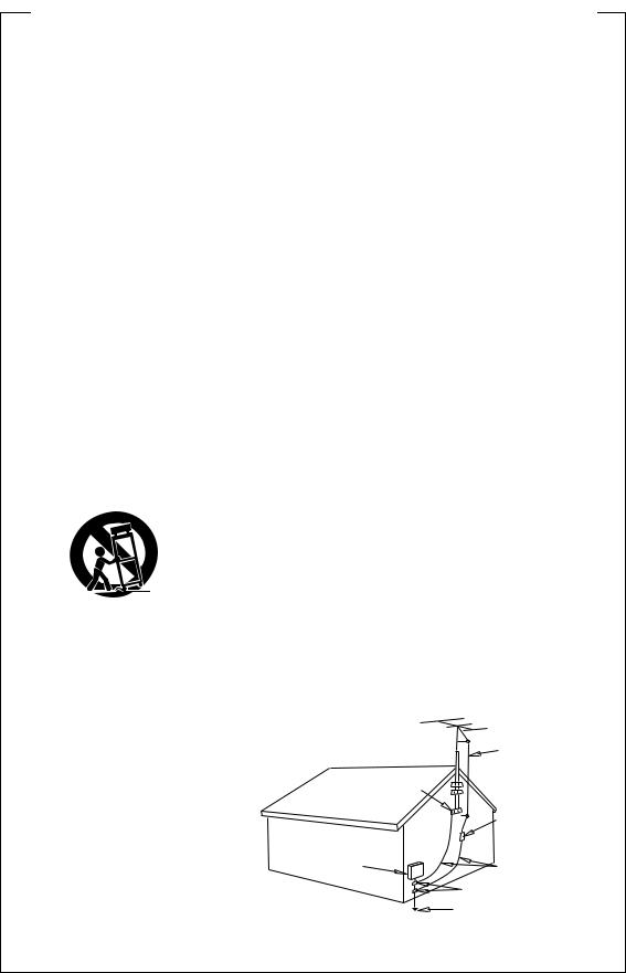
Optical Digital Connection
If your DVD player has an optical terminal (not a PCM-only output) for the audio out you can hook it up using this following the diagram on the next page. You will need to assign the digital input (tell the receiver which input you put your DVD digital audio into). See p. 6 for this.
4
Quick Start Guide
VIDEO INPUT
RCA video cord
VSX-35TX |
R |
L |
|
VIDEO |
RCA video cord |
VIDEO |
OUT |
|
RCA stereo cord |
ANALOG |
STEREO |
L |
L |
R |
R |
DIGITAL
OUTPUT
optical cord

DVD player
(not a PCM-only output)
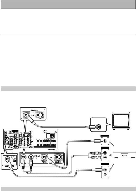
2 Speaker Connections
Home theater is designed to be setup with five, or seven speakers (front left & right; center; surround left & right; and, optimally, surround back left & right) and a subwoofer but you can use this receiver with fewer speakers. Hook up the speakers you have to the SPEAKERS A terminals on the back of the receiver. If you only have two speakers hook them up as "FRONT." If you have three, hook up the single speaker as "CENTER." Follow the diagram on p. 19 in order to hook up all your speakers. A center speaker is very important for watching films because the dialog comes from the center speaker in digital soundtracks. If you do not have a CENTER speaker you must tell the receiver the CENTER channel is OFF or when you listen to digital soundtracks you won't hear any dialog. Use the instructions on p. 33 – 34 in order to do this.
Follow the diagram below to hook up an additional amplifier in order to use surround back speakers. These speakers are important to hear all the sound channels on new, eight channel home theater DVDs. The diagram below also explains how to hook up a subwoofer which provides realistic bass sounds.
Make sure you connect the speaker on the right to the right terminal and the speaker on the left to the left terminal. Also make sure the positive and negative (+/–) terminals on the amplifier match those on the speakers.
RCA audio cord |
INPUT |
Powered |
|
||
|
|
subwoofer |
|
|
ANALOG |
Additional Amplifier (See p.21) |
|
|
|
|
INPUT |
|
|
|
R |
L |
|
R |
L |
R |
L |
SPEAKERS |
FRONT |
||||
RCA stereo cord |
R |
L |
|
|
|
|
Surround back |
Surround back |
|
speaker (Left) |
speaker (Right) |
5
Quick Start Guide
3 Setting up the Remote Control & Unit
1Put the batteries in the REMOTE CONTROL.
2Plug the main unit into an AC wall outlet.
3Press the  STANDBY/ON button on the receiver to put the receiver in ON mode.
4 Digital Input Assignment
This is only necessary if you did not hook up your DVD to DIGITAL IN 1, as in the first diagram on p. 4.
|
Î |
|
USE |
SETUP |
|
|
S0URCE |
|
|
|
RECEIVER |
|
|
MULTI |
SYSTEM |
|
|
|
|
OPERATION |
OFF |
|
|
|
DVD/LD |
TV/SAT |
VCR 1/ |
|
VCR2 |
|
DVR |
|
|||
|
|
MULTI CONTROL |
|
|
|
|
CD |
CD-R/ |
TUNER |
|
TV CONT |
|
TAPE 1 |
|
|||
|
CLASS |
MPX |
BAND |
DIRECT ACCESS |
|
|
¶ |
7 |
3 |
|
8 |
|
- TUNING + |
- STATION + |
|||
|
1 |
¡ |
4 |
¢ |
|
|
DTV ON/OFF DTV MENU |
- CHANNEL + |
|||
|
1 |
2 |
|
|
3 |
|
4 |
5 |
|
|
6 |
|
7 |
8 |
|
|
9 |
|
GUIDE |
0 |
|
|
EXIT |
|
|
|
ENTER |
||
|
+10 |
|
|
|
DISC |
|
+ |
TV |
|
|
+ |
|
TV VOL |
TV CONTROL |
VOLUME |
||
|
– |
TV FUNC |
|
– |
|
|
REMOTE SETUP |
|
|
|
|
|
INPUT |
MENU |
|
MUTE |
|
|
ATT |
|
|||
2 |
SYSTEM SETUP |
+ |
|
|
|
EFFECT/ |
|
|
FUNCTION |
||
|
CH SEL |
|
|
|
|
|
|
ENTER |
|
|
|
|
DIGITAL |
– |
|
|
SIGNAL |
|
NR |
|
|
SELECT |
|
|
MIDNIGHT |
MULTI CH |
DSP |
|
STEREO/ |
|
INPUT |
|
DIRECT |
||
|
|
|
/DTS |
|
|
|
LIGHT |
THX |
ADVANCED |
|
STANDARD |
AV PRE-PROGRAMMED AND LEARNING
REMOTE CONTROL UNIT
1
3-7
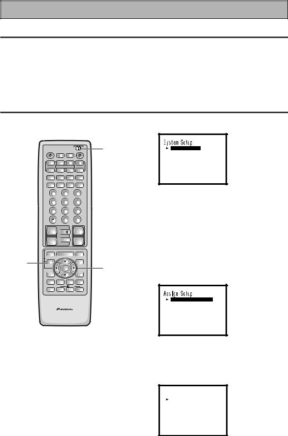
[ As s i gn S e t u p ]
[ S u r r o u n d S e t u p ] [ F u n c t i o n R en ame ] [ EX I T ]
•You can escape from this screen at any time by pressing the SYSTEM SETUP button again. None of the settings you made will be entered in this case.
•If don't enter any settings the receiver will revert back to its prevoius state after three minutes.
3Assign Setup should be selected, if it isn't use the 5¥ buttons to
select it. Press ENTER.
You should see the following display on your TV.
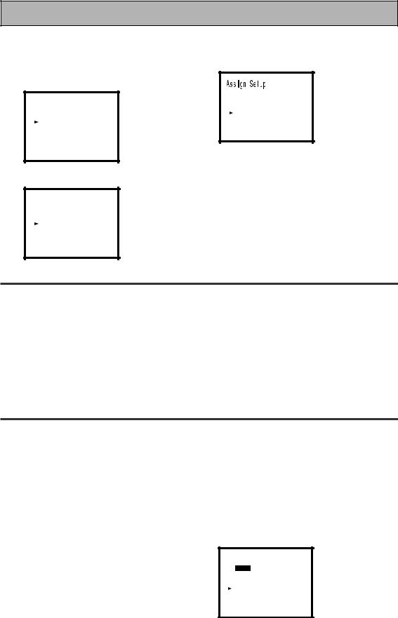
[ D i g i t a l - I n Se l e c t ] [ Mu l t i Ch a n ne l I n ]
[ C ompo n en t - I n Se l e c t ] [ Mu l t i - Ro om ]
[ EX I T ]
1 Set the remote control slide switch to SETUP.
Also make sure your TV is on and set to the receiver.
•When you're done setting up the receiver, remember to set the slide switch back to USE.
2 Press the SYSTEM SETUP button.
You should see the following display on your TV.
4Digital in Select should be selected, if it isn't use the 5¥ buttons to
select it. Press ENTER.
You should see the following display on your TV.
D i g i t a l - i n Se l e c t
D i g i t a l - 1i |
[ DVD / LD ] |
|
D i g i t a l - 2i |
[ |
CD ] |
D i g i t a l - 3i |
[ |
CD - R ] |
D i g i t a l - 4i |
[ TV / SAT ] |
|
[ EX I T ]
6
Quick Start Guide
5Choose the Digital-3 you hooked up your DVD player to on p. 4 – 5 and assign "DVD/LD" to it.
6Select EXIT with 5¥ buttons and press ENTER to return to the Assign Setup menu.
1Use the 5¥ buttons to choose the Digital-3 and press ENTER.
D i g i t a l - i n Se l e c t
D i g i t a l - 1i |
[ DVD / LD ] |
||
D i g i t a l - 2i |
[ CD ] |
||
D i g i t a l - 3i |
[ |
DVD / LD |
] |
D i g i t a l - 4i |
[ |
TV / SAT |
] |
[ EX I T ] |
|
|
|
2Use the 5¥ buttons to choose the DVD/LD setting and press ENTER.
[ D i g i t a l - I n Se l e c t ] [ Mu l t i Ch a n ne l I n ]
[ C ompo n en t - I n Se l e c t ] [ Mu l t i - Ro om ]
[ EX I T ]
7Select EXIT with 5¥ buttons and press ENTER to return to the System Setup menu.
D i g i t a l - i n Se l e c t
D i g i t a l - 1i D i g i t a l - 2i D i g i t a l - 3i D i g i t a l - 4i
[ EX I T ]
[ |
OF F |
] |
[ |
CD |
] |
[ DVD / LD ] [ TV / SAT ]
5 Playing a DVD with Surround Sound
1 |
Turn on the receiver, your TV, and |
3 |
Press the STANDARD button for the |
|
the DVD player. |
|
basic surround sound setting. |
2 |
Set the remote control slide switch |
4 |
Play a DVD. |
|
to USE. Press the DVD/LD button |
|
|
|
on the remote control. |
|
|
You should see "DVD/LD" in the display on the receiver.
6 For Better Surround Sound
1Go through the entire "Initial Setup" procedures as outlined on p. 27 – 40
of this instruction manual.
If you don't hook up any other conmponents with digital audio or do so following the default settings of the receiver (see p. 15) you won't have to assign any more digital inputs, but many other adjustments will improve the sound tremendously.
2Experiment with the different sound settings offered with the 2/DTS
and DSP buttons.
For more information see p. 41 – 45.
3As mentioned above you should go through the "speaker setting" instructions on p. 28 – 40 to set up your speakers properly. If you don't do this you, at least, need to make sure the CENTER channel is turned off if you don't have a center speaker. Use the instructions on
p. 33 – 34.
Sp e a k e r Se t t i n g
[ FREE t] [ THX ]
F r o n t |
[ LARGE ] |
Ce n t e r |
[ NO ] |
Su r r o u n d |
[ LARGE ] |
Su r r B a c k |
[ LARGE x 2 ] |
Su bwo o f e r |
[ YES ] |
[ EX I T ] |
|
7
Features
Multi Channel Stereophonic Concept
The VSX-35TX receiver is constructed with Pioneer’s industry-leading multi channel stereophonic concept. This well-developed approach to receiver circuitry takes the high level base technology that, up until now, has been only used for stereo equipment and applies it to multi-channel audio-visual receivers. The result is that the product, in addition to being expertly built, and gives you optimal sound reproduction of DVDs, other multi channel sources and stereo sources as well. This receiver is designed capture to a true reproduction of the intentions of a filmmaker or music producer at the time they were mastering the soundtrack in the studio. It incorporates 5 independent 90 watt built in power amplifiers, with high-performance Hex power Direct Power MOS FET output transistors. The isolated chamber construction cuts off unwanted electrical influences from the digital circuitry and allows accurate representation of each channel for true high fidelity reproduction from even the most demanding Dolby Digital and DTS program sources. In addition, the amplifier uses Direct Construction to give the purest sound available. All these elements consolidated in one receiver afford the listener a new surround sound experience in his or her home.
Universal Player Compatibility
This receiver incorporates the latest technology and is able to handle cutting edge audio formats, like DVD Audio, which are just hitting the market. Its high compatibility offers a variety of inputs to decode all types of sources at the highest possible quality. The receiver’s multi channel in connections lets you hook up eight discrete channels of audio. It also has multi channel direct inputs and the ability to decode the cutting edge formats.
Decoding of Next Generation Digital Source Film Formats
Built into this receiver is the latest in film sound format technology. This technology includes the recent THX SURROUND EX and HOME THX CINEMA surround modes which employ special processing to allow you to enjoy movie soundtracks with the same level of power and realism you experience in well-designed movie theaters. The THX SURROUND EX mode has been especially designed to incorporate surround back channels that some new source material uses. This receiver has the ability to decode Dolby Digital, Dolby Pro Logic and
DTS (Digital Theater Systems) sources, which are the standards of home theater today. It also offers component video terminals for the sharpest video transmission available to the consumer.
Manufactured under license from Lucasfilm Ltd. U.S. patent numbers 5,043,970; 5,189,703; and/or 5,222,059. European patent number 0323830. Other U.S. and foreign patents pending. Lucasfilm and THX are registered trademarks of Lucasfilm Ltd. Surround EX is a trademark of Dolby Labs. Used under authorization.
“DTS”, "ES" and “DTS Digital Surround” are trademarks of Digital Theater Systems, Inc. Manufactured under licence from Digital Theater Systems, Inc.
Manufactured under license from Dolby Laboratories. “Dolby”, “Pro Logic”, and double-D symbol are trademarks of Dolby Laboratories. Confidential unpublished works.
© 1992 - 1997 Dolby Laboratories. All rights reserved.
Advanced Theater Modes & DSP Surround Modes
Advanced Theater modes enhance the sound of either film or music so a more dramatic effect can be achieved. The four modes are each designed to accentuate specific sound qualities, giving the listener a wide range of possibilities. DSP (Digital Signal Processing) surround modes give you the capability of transforming your living room into seven different sonic environments when listening to music.
Midnight Mode, Digital Noise Reduction & 7 Channel Tone Control
The Midnight mode allows you to obtain excellent surround sound effects even when listening at low volumes, something that was previously impossible. Digital noise reduction filters out unwanted noise from recordings to give you a clearer sound and the 7 channel tone control allows you to adjust the treble and bass of each channel individually to suit your listening tastes.
Remote Control with Illuminated Buttons
This improved remote control is extremely convenient to use. Its buttons can be easily viewed as they illuminate when functions are preformed. In addition, one button can perform many tasks on this remote because of the Use and Setup switch, which allows different uses for the same button in the different settings. This remote can be used to operate a variety of other components simply by recalling the appropriate setup codes or by using the learning function to teach the remote control new commands. In addition, the multi-operation functions allow you to perform a variety of operations automatically.
The Energy-saving Design
8 This unit is designed to use less than 1 W of energy when the receiver is in standby mode.

Table of Contents
Quick Start Guide............................... |
4 Remote Control of Other Components .. 58 |
Before You Start ................................. |
10 |
Checking the Supplied Accessories ........................ |
10 |
How to Use This Manual .......................................... |
10 |
Preparing the Remote Control ................................. |
10 |
Installing the Receiver .............................................. |
11 |
Opening the Front Panel .......................................... |
11 |
Connecting Your Equipment ............. |
12 |
Audio Components ................................................... |
12 |
Digital Connections .................................................. |
13 |
Video Components ................................................... |
14 |
Example Connection for a DVD/LD or LD player .... |
15 |
Satellite TV Components ......................................... |
16 |
TV ............................................................................... |
17 |
Multi Channel Input (External Decoder) ................. |
17 |
Connecting the Radio Antennas .............................. |
18 |
Speakers .................................................................... |
19 |
Placing Your Speakers .............................................. |
20 |
Connecting Additional Amplifiers ........................... |
21 |
Plugging In ................................................................ |
21 |
Setting Up the Remote Control to Control Other |
|
Components .............................................................. |
58 |
Using the Remote Control with |
|
Other Components ................................................... |
62 |
Using Other Functions....................... |
69 |
Function Rename ...................................................... |
69 |
Recording from Audio Components ....................... |
71 |
Recording from Digital Audio Components ........... |
72 |
Recording from Video Components ....................... |
72 |
Multi Operations ....................................................... |
73 |
System Off ................................................................. |
75 |
Setting Up the Direct Function ................................ |
76 |
Remote Back Light .................................................... |
77 |
Resetting the Remote Control ................................. |
77 |
Erasing Learned Remote Control Commands ........ |
78 |
Erasing All Learned Commands and Preset Codes ... |
78 |
Video Select .............................................................. |
79 |
Changing the Display ............................................... |
79 |
Multi-Room ............................................................... |
80 |
|
|
|
Techno Tidbits & Problem-solving |
86 |
|
Displays & Controls |
22 |
||||
Dolby Digital |
86 |
||||
Front Panel |
22 |
|
|||
|
DTS |
86 |
|||
Remote Control |
24 |
|
|||
|
THX |
87 |
|||
Display |
26 |
|
|||
|
Preset Code List |
88 |
|||
|
|
|
|||
Initial Set Up |
27 |
........................................................Troubleshooting |
89 |
||
Specifications |
92 |
||||
On Screen Display |
27 |
|
|||
|
|
|
|||
Setting Up for Surround Sound .............................. |
28 |
|
|
|
|
|
|
|
|
|
|
Basic Playback .................................... |
41 |
|
|
|
|
Sound Modes ............................................................ |
41 |
|
|
|
|
Selecting a Sound Mode .......................................... |
44 |
|
|
|
|
Playing Sources with |
|
|
|
|
|
Dolby Digital or DTS Sound ..................................... |
45 |
|
|
|
|
Playing Stereo Sources ............................................ |
46 |
|
|
|
|
Switching Analog and Digital Signal Input ............ |
47 |
|
|
|
|
Reducing Noise During Playback ............................ |
48 |
|
|
|
|
Listening in Midnight Mode ..................................... |
49 |
|
|
|
|
Listening the Loudness Mode ................................. |
49 |
|
|
|
|
Adjusting Bass and Treble ....................................... |
50 |
|
|
|
|
MULTI CHANNEL IN Playback ................................. |
51 |
|
|
|
|
96kHz 24bit Performance ......................................... |
51 |
|
|
|
|
Direct Playback .......................................................... |
52 |
|
|
|
|
Adjusting the Brightness of the Display ................. |
52 |
|
|
|
|
DUAL MONO Setting ................................................ |
53 |
|
|
|
|
|
|
|
|
|
|
Using the Tuner .................................. |
54 |
|
|
|
|
Automatic and Manual Tuning ................................ |
54 |
|
|
|
|
Direct Access Tuning ................................................ |
55 |
|
|
|
|
Memorizing Frequently Used Stations ................... |
56 |
|
|
|
|
Recalling Memorized Stations ................................. |
57 |
|
|
|
|
PREPARATION
SET UP
OPERATION
9
Before You Start
Checking the Supplied Accessories
Please check that you have received all of the following supplied accessories.
FM wire Antenna |
AM loop Antenna “AA” IEC LR6 |
Remote Control Unit |
|
batteries x 2 |
• Operating Instructions |
|
|
How to Use This Manual
This manual is for the VSX-35TX Audio/Video MultiChannel Receiver.
This manual is divided into three main sections which will tell you how to setup and use the unit :
PREPARATION
First carry out the tasks below in this “Before You Start“ section to prepare the remote control, then connect the receiver to your other components as described in “Connecting Your Equipment“ (p.12). Take special care to connect your digital equipment like DVDs and LDs properly to be able to take advantage of the receiver’s surround sound systems (p.13-15). To learn about a specific button, control, or indicator, see “Displays & Controls“ starting on p.22.
SET UP
Performing the tasks in “Initial Setup“ (from p.27) is essential to get proper surround sound.
OPERATION
To play some music or soundtrack refer to “Basic Playback“ on p.41. “Using the Tuner“ (p.54) explains how to use the radio of this unit. Doing the operations in “Remote Control of Other Components“ (p.58) is highly recommended so you can use this unit’s remote control for all your components. “Using Other Functions“ (p.69) explain the other possibilities of the receiver.
“Techno Tidbits & Problem-solving“ (p.86) provide detailed technical information and a troubleshooting guide.
The following marks and symbols are used throughout the manual:
memo |
Provides additional information, |
|
precautions, and advice. |
Indicates a blinking button, indicator, or display.
Indicates a steadily lit button, indicator, or display.
Preparing the Remote Control
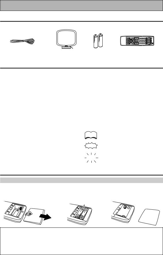
Loading the batteries
Load the batteries into the remote control as shown below. Please use alkaline batteries. When you notice a decrease in the operating range of the remote control, replace all batteries with new ones.
1 |
2 |
“AA” IEC LR6 |
|
|
batteries x 2 |
\
3
\ 


CAUTION!
Incorrect use of batteries may result in such hazards as leakage and bursting. Observe the following precautions.
•Never use new and old batteries together.
•Insert the plus and minus sides of the batteries properly according to the marks in the battery case.
•Batteries with the same shape may have different voltages. Do not use different batteries together.
•When disposing of used batteries, please comply with governmental regulations or environmental public institution’s rules that apply in your country / area.
10
Before You Start
Operating range of remote control unit
The area in which you can use the remote control to operate the VSX-35TX is fairly large. To use, point the remote control toward the remote sensor on the front panel of this unit while within the range shown below.
Remote control may not function properly if:
•There are obstacles between the remote control and the remote sensor.
•Direct sunlight or fluorescent light is shining onto the remote sensor.
•The receiver located near a device emitting infrared
rays. |
30 |
• Operated simultaneously with another remote control |
|
which uses infrared rays. |
30 |
|
23 feet (7 m) |
Installing the Receiver |
|
Please note: |
|
• Do not place objects directly on top of this unit. This would |
8 inches (20 cm) |
prevent proper heat dispersal. |
|
• When installing in a rack, shelf, etc., be sure to leave more |
|
than 8 inches of space above the receiver. |
|
|
Receiver |
Opening the Front Panel |
|
To open the front panel push gently on the lower third of the panel |
|
with your finger. |
|
PREPARATION
11
Connecting Your Equipment
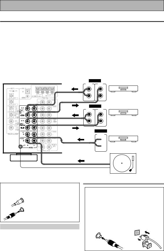
Audio Components
To begin set up connect your audio components to the jacks as shown below. These are all analog connections and your analog audio components (turntable, cassette deck) use these jacks. Remember that for components you want to record with you need to hook up four plugs (a set of stereo ins and a set of stereo outs), but for components that only play (like a turntable) you only need to hook up one set of stereo plugs (two plugs). To use DTS or Dolby Digital surround sound features you must hook up your digital components to the digital inputs (see p. 13). We also recommend hooking up your digital components to analog audio jacks. If you want to record to/from digital components (like an CD-R) to/from analog components you must hook up your digital equipment with these analog connections. See p.13 & 15 for more on digital connections.
Before making or changing the connections, switch off the power and disconnect the power cord from the AC wall outlet.
*The arrows indicate the direction of the audio signal.
ANALOG
OUTPUT |
INPUT |
(PLAY) |
(REC) |
L |
L |
R |
R |
ANALOG |
|
OUTPUT |
INPUT |
(PLAY) |
(REC) |
L |
L |
R |
R |
|
ANALOG |
|
OUTPUT |
 L
L
 R
R
Please don't hook up any other component to the PHONO jacks other than a turntable. It could damage the equipment. If your turntable has a built-in amplifier please hook it up to an input other than the PHONO.
Recorder 1 (CD-R/Tape)
Recorder 2
CD player
Turntable
If your turntable has a ground wire, connect it to the SIGNAL GND terminal.
7 Analog audio/video cords
Use audio/video cords (not supplied) to make analog audio and video connections.
L |
Connect red plugs to R (right) |
|
and white plugs to L (left). |
R |
Be sure to insert completely. |
Cassette deck placement
Depending on where the cassette deck is placed, noise may occur during playback of your cassette deck which is caused by leakage flux from the transformer in the receiver. If you experience noise, move the cassette deck farther away from the receiver.
7Coaxial cords/Optical cables
Commercially available digital audio coaxial cords (standard video cords can also be used) or optical cables (not supplied) are used to connect digital components to this receiver.
When you use optical digital input or output terminals, pull off the caps and insert the plugs. Be sure to insert completely.
Coaxial cord |
Optical cable |
(or standard video cord) |
|
12
Connecting Your Equipment
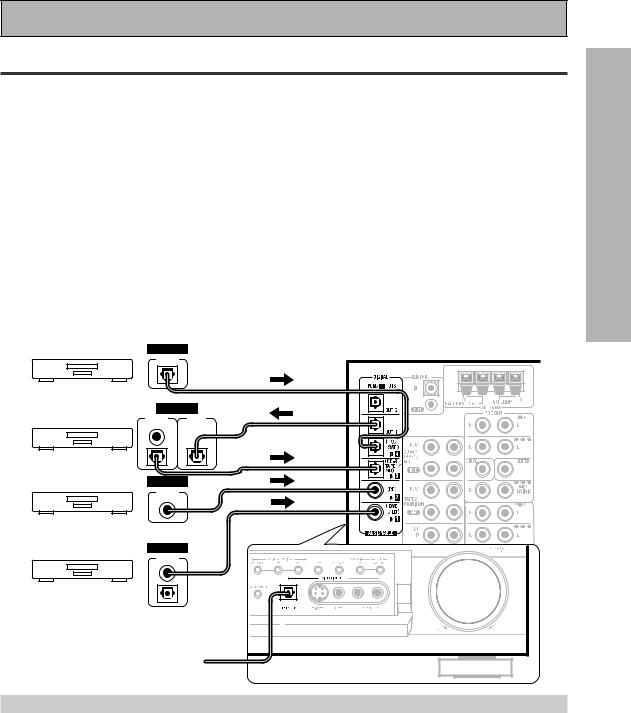
Digital Connections
In order to use Dolby Digital/DTS soundtracks which are at the heart of home theater you need to make digital audio connections. You can do this by either a coaxial or an optical connection (you don’t need to do both). The quality of these two types of connections is the same but since some digital components only have one type of digital terminal, it is a matter of matching like with like (for example, the coaxial out from the component to coaxial in on the receiver). The VSX-35TX has two coaxial and three optical inputs for a total of five digital inputs. For a DVD/LD player or LD player hook up see p.15. If possible hook up your digital equipment in accordance with this receiver's default settings, see "Digital Input Assignment," below, in order to do this. We also recommend hooking up your digital components to analog audio jacks in order to make recording from some digital sources which may be copy protected.
Connect your digital components as shown below.
There are two optical digital out jacks (the CD recorder is connected to one in the diagram below). If you connect this to the optical input on a digital recorder (currently these include MD, DAT and CD-R) you can make direct digital recordings with this unit.
Before making or changing the connections, switch off the power and disconnect the power cord from the AC wall outlet.
*The arrows indicate the direction of the audio signal.
DIGITAL
OUTPUT
TV tuner
DIGITAL
OUTPUT |
INPUT |
(PLAY) |
(REC) |
CD recorder
DIGITAL
OUTPUT
CD player
(not a PCM-only output) DIGITAL
OUTPUT
DVD player
(for DVD/LD player hook up see p.15)
Front DIGITAL IN connection is  accessed via the input selector
as "VIDEO"
Digital Input Assignment
Unlike analog connections, the jacks for digital connections are not dedicated to one type of component, they can be used freely. Thus you must tell the receiver what digital componenet in which jack so your components will be in sync with the the names on the remote control buttons and the like. To avoid having to assign the digital inputs you can hook up your equipment in accordance with the receiver's default settings.
The default settings are:
DIGITAL IN 1: |
DVD/LD |
DIGITAL IN 3: |
CD-R |
DIGITAL IN 2: |
CD |
DIGITAL IN 4: |
TV/SAT |
You will notice that Digital IN 1, for example, is a coaxial jack. If your DVD/LD player only has an optical out jack on it then you won't be able to hook up your components in accordance with the VSX-35TX default setting. In this case you will need to assign the digital inputs. See Digital-In Select on p.30 in order to do this.
PREPARATION
13

Connecting Your Equipment
Video Components
Connect your video components to the jacks as shown below. Regarding a DVD there are two types of connections to make. Hook up your video signal with either component video, S-video, or composite video cords (the quality descends in this order) but remember, the video component you are watching and your TV must be hooked up with same type of video cord or you won't be able to see the picture. For the audio signal, order to use Dolby Digital/DTS you must hook up a digital input. It is also a good idea to hook up your DVD components with analog audio connections as well, since some DVDs may not have a digital audio track. To cover all possible LaserDiscs a DVD/LD player or LD player requires an analog connection and two digital connections (a coaxial or optical and a specialized RF demodulator connection shown on the next page).
Before making or changing the connections, switch off the power and disconnect the power cord from the AC wall outlet.
*The arrows indicate the direction of the video signal.
Connecting DVD players
VIDEO |
|
COMPO- |
VIDEO |
NENT |
OUT |
Y |
|
PB |
S-VIDEO |
|
|
PR |
|
ANALOG DIGITAL |
|
STEREO |
PCM/ |
|
2/ DTS |
L |
DIGITAL |
|
|
R |
|
(not a PCM-only output)
DVD/LD player
If you hook up your DVD player using component video connections be sure to select component video output on your DVD player as well. See you DVD manual for details.
Connecting VCRs or DVRs
OUT |
IN |
|
AUDIO |
AUDIO |
|
(PLAY) |
(REC) |
|
L |
L |
|
R |
R |
|
VIDEO |
VIDEO |
|
|
|
VCR 1/DVR |
S-VIDEO S-VIDEO |
|
|
OUT |
IN |
|
AUDIO |
AUDIO |
|
(PLAY) |
(REC) |
|
L |
L |
|
R |
R |
VCR 2 |
VIDEO |
VIDEO |
|
S-VIDEO S-VIDEO
|
|
|
Portable |
|
|
|
DVD |
V |
L |
R |
player |
VIDEO OUTPUT |
|
(etc.) |
|
Front video connections are accessed via the front panel input
14 selector as "VIDEO."
memo If your video components have S-video jacks, you could use  S-video cords (not supplied) to connect them on the back of the receiver. These jacks are labeled by the Japanese designation "S2" on the VSX-35TX but they are simply S-video jacks.
if you use S-video cords for your video hook ups you must also hook up your TV with S-video connections. This holds true with all cord types. If you use regular composite video cords for video hook ups, you should use them for your TV as well. If you use the high-grade component video cords for your video connection you must use them for your TV hook up as well (some TVs may not be able to do this).
Connecting Your Equipment
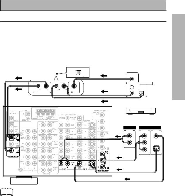
Example Connection for a DVD/LD or LD player
Make sure you connect your DVD/LD or LD players using both a RF demodulator and either a coaxial or optical (you don't need to do both of these) digital connections. To connect a DVD/LD player or LD player with it's 2RF output, a commercially available RF demodulator (RFD-1) is required. The RF demodulator changes the RF signal to a digital signal which is then processed by the VSX-35TX model through their digital input jacks. For more details, refer to the instruction manual supplied with the RFD-1. If your player has an 2RF output this will ensure you can use all LDs. We also recommend hooking up your digital components to analog audio jacks.
Before making or changing the connections, switch off the power and disconnect the power cord from the AC wall outlet.
*The arrows indicate the direction of the audio signal.
RF demodulator RFD-1 |
|
DIGITAL IN |
|
|||||||
|
|
|
|
|
|
|
|
|
|
2RF OUT |
|
|
|
|
|
|
|
OPTICAL COAXIAL |
(AC-3)(LD) |
||
|
|
|
|
|
|
|
|
|
|
|
DIGITAL OUT
1 
PCM/ |
PCM/ |
PCM/ |
PCM/ |
|
|
|
|
(OPT.) |
|
(OPT.) |
|
RF IN |
2 |
3 |
|
DIGITAL OUT |
DIGITAL IN |
||||||
(AC-3)(LD) |
|||||||
|
|
|
|
||||
memo |
(not a PCM-only output)
DVD/LD player or LD player
ANALOG VIDEO
STEREO |
COMPO- |
VIDEO |
|
NENT |
OUT |
L |
Y |
|
R |
PB |
S-VIDEO |
|
PR |
|
Be sure to make either a digital coaxial or digital optical connection (pictured as DIGITAL jack 1 or DIGITAL jack 3 in this diagram) as well, but you DON'T need to make both.
Make sure the RF demodulator digital in switch is set correctly (optical or coaxial depending on the connection).
Also, be sure to assign the jacks to the proper component(s) with the Digital-In Select procedure (see p. 30 and/or the explanation on the left for details.) if necessary. See the components instruction manual if you are unsure about its input and output jacks.
PREPARATION
15
Connecting Your Equipment
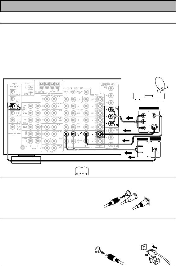
Satellite TV Components
Connect your satellite TV components to the jacks as shown below. Hook up the video signal with either component video, S-video, or composite video cords (the quality descends in this order) but remember, the video component you are watching and your TV must be hooked up with same type of video cord or you won't be able to see the picture. For the audio signal, order to use digital soundtracks (sometimes broadcast over digital satellite TV) you must hook up a digital input. Use either a coaxial or optical cables, it doesn't matter which (you don't need to use both). It's also a good idea to hook up your audio with analog cables (see below). This connection is called STEREO AUDIO OUT in the diagram.
Before making or changing the connections, switch off the power and disconnect the power cord from the AC wall outlet.
*The arrows indicate the direction of the TV signal.
TV/Satellite tuner
VIDEO |
|
COMPO- |
VIDEO |
NENT |
OUT |
Y |
|
PB |
S-VIDEO |
PR |
|
ANALOG DIGITAL
STEREO DIGITAL
 L
L
 R
R
memo See the components instruction manual if you are  unsure about its input and output jacks.
7 Analog audio/video cords
Use audio/video cords (not supplied) to connect the video components and a video cord to connect the monitor TV.
Connect red plugs to R (right), white plugs to L (left), and the yellow plugs to VIDEO.
Be sure to insert completely.
R
L
VIDEO
7Digital audio coaxial cords/
Optical cables
Commercially available digital audio coaxial cords (standard video cords can also be used) or optical cables (not supplied) are used to connect digital components to this receiver.
When you use optical digital input or output terminals, pull off the caps and insert the plugs. Be sure to insert completely.
Digital audio coaxial |
Optical cable |
cord |
|
(or standard video cord)
16
Connecting Your Equipment
TV
Connect your TV to the jacks as shown below. Hook up the signal with either component video, S-video, or composite video cords (the quality descends in this order) but remember, the video component you are watching and your TV must be hooked up with same type of video cord or you won't be able to see the picture. Before making or changing the connections, switch off the power and disconnect the power cord from the AC wall outlet.
TV/monitor
VIDEO IN
COMPO- |
VIDEO |
NENT |
|
 Y
Y
 PB S-VIDEO
 PR
PR
memo The COMPONENT VIDEO OUT jack can be used to get a TV picture  but it doesn't show this receiver's on screen display (OSD).
Multi Channel Input (External Decoder)
In some cases you may want to have you source material (DVD, etc) decoded externally. If you find you need a multi channel external decoder hook one up as shown below, but for most people this component is unnecessary (For more on this see p.51).
Before making or changing the connections, switch off the power and disconnect the power cord from the AC wall outlet.
Components equipped with
7.1 or 5.1 channel analog output jacks
ANALOG
SURR- |
SUB |
CENTER |
SURR- |
FRONT |
OUND BACK |
WOOFER |
|
OUND |
|
L |
|
|
L |
L |
R |
|
|
R |
R |
PREPARATION
17
Connecting Your Equipment
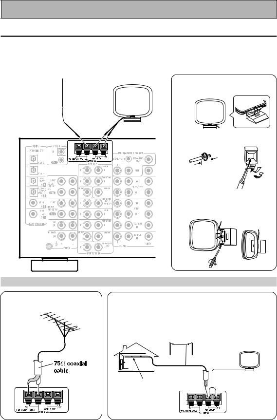
Connecting the Radio Antennas
Connect the supplied FM wire antenna and the AM loop antenna to the antenna terminals as shown below. These antennas should provide adequate reception quality in most cases, but connecting outdoor antennas should noticeably improve sound quality.
Before making or changing the connections, switch off the power and disconnect the power cord from the AC wall outlet.
FM wire antenna |
AM loop antenna |
7 AM loop antenna |
|
||
|
|
1 Assemble the antenna. |
2 Twist exposed wire strands together and insert.
|
.(10 |
mm) |
3/8 |
in |
|
|
|
3 Attach to a wall, etc. (if desired) and face toward the direction providing the best reception.
Using external antennas
7 To improve FM reception
Connect an external FM antenna.
7 To improve AM reception
Connect a 15-18 feet (5-6 meter) length of vinyl-coated wire to the AM antenna terminal in addition to the supplied AM loop antenna.
For best possible reception, suspend horizontally outdoors.
Outdoor antenna
AM loop antenna
15–18 ft. (5–6 m)
Indoor antenna (vinyl-coated wire)
18
Connecting Your Equipment
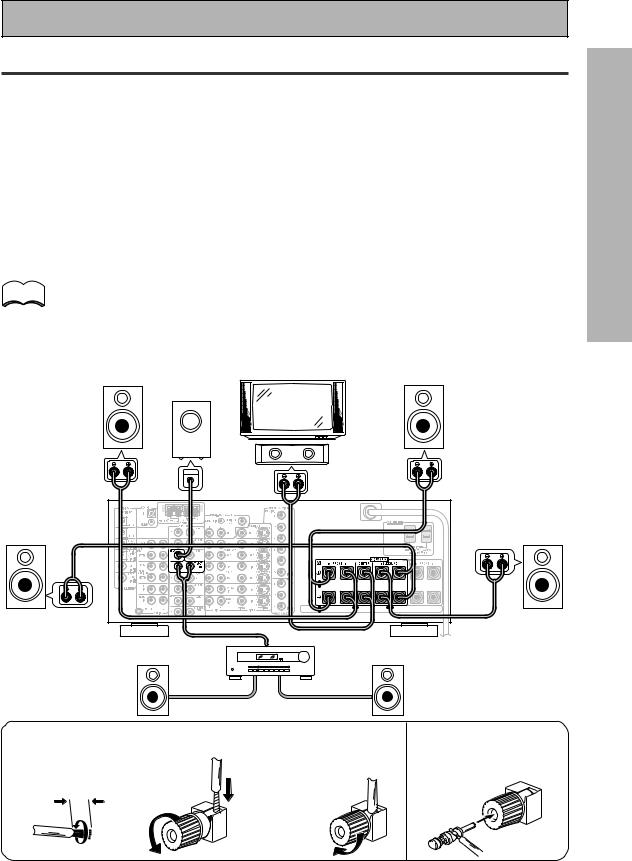
Speakers
A full complement of eight speakers is shown here but, naturally, everyone's home set up will vary. Simply connect the speakers you have in the manner described below. The receiver will work with just two stereo speakers (called "front" speakers in the diagram) but the receiver is designed to be used with at least three speakers.
One of the latest features of home theater is the use of SURROUND BACK speakers. These speakers add even greater realism in movie sound effects and new discs with soundtracks in Dolby Digital or DTS incorporates these channels. In order to be able to use these channels you must hook your SURROUND BACK speakers up to an external amplifier and then connect that to the VSX-35TX, as shown in the diagram below. If you only have one SURROUND BACK speaker hook it up to the SURROUND BACK L (SINGLE) terminal on the back of the receiver.
In general, make sure you connect the speaker on the right to the right terminal and the speaker on the left to the left terminal. Also make sure the positive and negative (+/–) terminals on the receiver match those on the speakers. Before making or changing the connections, switch off the power and disconnect the power cord from the AC wall outlet.
The receiver has two speaker systems, A & B. A is the main system supporting the full complement of surround memo sound speakers. If you switch on both A & B speaker systems, only front speakers and the sub-woofer will be
audible. No sound will come from the center or surround speakers but multi channel sources will be down-mixed to the active speakers so no sound will be lost. Similarly, if you choose just the B system you‘ll only hear the front speakers connected to the B system and multi channel sources will be down-mixed to these two speakers.
For the VSX-35TX you can use speakers with a nominal impedance rated 6Ω-16Ω, see the following page.
|
Powered |
|
Front |
subwoofer |
Front |
TV/monitor |
||
speaker (A) |
|
speaker (A) |
(Left) |
|
(Right) |
|
Center |
|
speaker |
|
INPUT |
Surround |
Surround |
speaker |
speaker |
(Left) |
(Right) |
Additional Amplifier (See p.21) (Pioneer A-35R etc.)
Surround back |
|
|
Surround back |
|
speaker (Left) |
|
|
speaker (Right) |
|
7 Speaker terminals 2 Loosen speaker terminal |
3 Tighten |
The speaker terminals |
||
1 Twist exposed wire |
and insert exposed wire. |
terminal. |
also accept single banana |
|
plugs. |
||||
|
|
|||
strands together. |
|
|
||
|
|
(Refer to speaker manual |
||
|
|
|
||
3/8 in. (10 mm) |
|
|
for details.) |
|
|
|
|
||
PREPARATION
19
Connecting Your Equipment
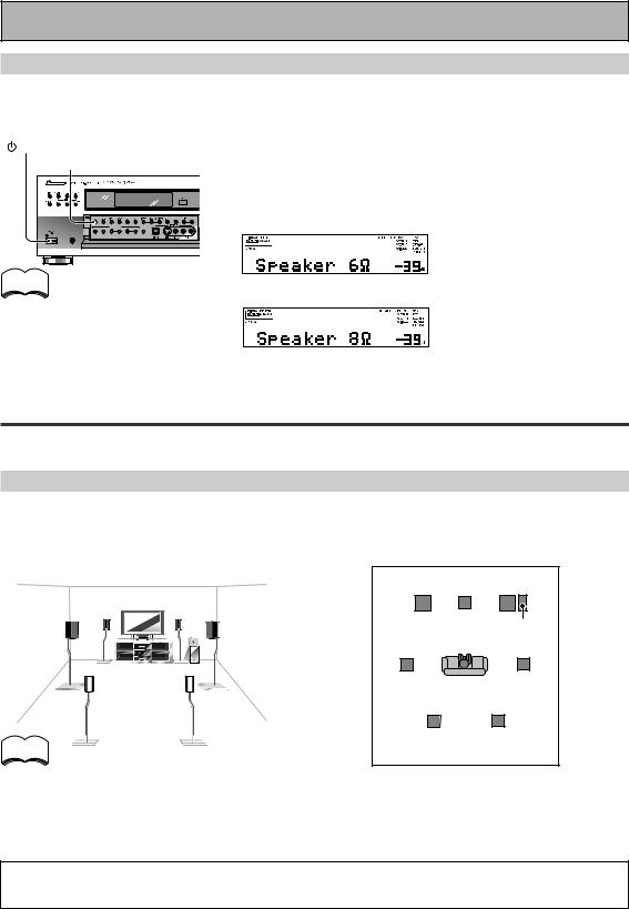
Speaker impedance
You can change the speaker impedance for VSX-35TX but we recommend using speakers with an impedance of 8Ω-16Ω (the default setting). If you are using 6Ω- less than 8Ω impedance speakers, you need to change the impedance setting. Use any speaker rated between 6Ω-16Ω.
STANDBY/ON |
First put the receiver in STANDBY mode, then press the power |
SPEAKERS |
button while holding down the SPEAKERS button. |
|
The receiver will re-set to the new impedance setting. You can |
|
choose the 8Ω-16Ω setting or the 6Ω-8Ω setting. |
|
(This display indicates a 6Ω- |
|
less than 8Ω impedance |
memo |
setting.) |
|
To check which impedance setting to hold down the SPEAKERS button for 2-3 seconds. You'll get a display like these telling you the speaker impedance setting.
(This display indicates an 8Ω- 16Ω impedance setting.)
Placing Your Speakers
Proper speaker placement is essential to realize the best sound from your system. The diagram and tips given here are just a rough guide; be sure to read the instructions that come with your speakers.
Speaker placement
If you have a multiple speaker arrangement the placement of the speakers is extremely important. To achieve the best possible surround sound, install your speakers as shown below. Make sure all speakers are installed securely to prevent accidents and improve sound quality. Be sure to consult your speaker manuals for the best placement of the speakers. Some speakers are designed to be floor-standing but others benefit greatly from speakers stands which raise them off the floor.
|
Front |
|
Front |
|
Left |
Center |
Right |
|
|
|
Sub |
|
|
|
Woofer |
|
Surround |
Listening |
Surround |
|
Left |
Right |
|
|
Position |
||
|
|
|
|
memo |
Surround Back Surround Back |
||
Left |
|
Right |
|
•Install the left and right front speakers at equal distances from the TV.
•When installing speakers near the TV, we recommend using magnetically shielded speakers to prevent possible interference such as distortion in the color of the TV screen. If you do not have magnetically shielded speakers and notice discoloration of the TV screen, place the speakers farther away from the TV.
•Install the center speaker above or below the TV so that the sound of the center channel is localized at the TV screen.
CAUTION:
When installing the center speaker on top of the TV, be sure to secure it with tape or some other suitable means. Otherwise, the speaker may fall from the TV due to external shocks such as earthquakes, and it may lead to endangering those nearby or damaging the speaker.
•If possible, install the surround speakers slightly above ear level.
•It may be difficult to obtain a cohesive surround effect if the surround speakers are installed farther away from the listening position than the front and center speakers.
20
Connecting Your Equipment
Connecting Additional Amplifiers
To hook up surround back speakers you need to use an additional amplifier. Other than for that purpose this receiver has more than sufficient power for any home use, but it is possible to add additional amplifiers to every channel of your system. Make the connections shown below to add amplifiers to power your speakers. Before making or changing the connections, switch off the power and disconnect the power cord from the AC wall outlet.
|
ANALOG |
|
|
|
L |
INPUT |
|
|
R |
Front channel amplifier |
|
|
|
|
|
|
ANALOG |
|
|
|
L |
INPUT |
|
|
R |
Surround channel amplifier |
|
|
|
|
|
|
ANALOG |
|
|
|
|
INPUT |
Center channel amplifier |
|
|
|
|
|
|
|
(mono) |
|
ANALOG |
|
|
|
|
INPUT |
|
|
|
|
Powered sub woofer |
|
ANALOG |
|
|
|
|
INPUT |
Surround back channel |
|
L |
R |
|
|
|
|
amplifier |
memo |
You can use the additional amplifier on the surround back channels |
||
|
for a single speaker as well. In this case plug the amplifier into the L |
||
|
(SINGLE) terminal only. |
|
|
Plugging In
Up to two components can be powered from this receiver. Two of the outlets are switched, which means that power is switched on and off with the receiver.
Before making or changing the connections, switch off the power and disconnect the power cord from the AC wall outlet.
After connecting all your components, plug the receiver's power cord into a standard wall power outlet.
Caution!
Power consumption of any equipment connected to the switched power outlets should not exceed 100W (0.8 A).
To avoid overheating, fire risk and possible malfunction, do not connect high-wattage appliances such as heaters, irons, monitors or TV sets to this units AC outlets.
Disconnect the receiver from the power outlet when it's not in regular use, for example, when on vacation.
Caution!
Do not connect a monitor or TV to this unit's
AC OUTLETS.
PREPARATION
21
Displays & Controls
Front Panel
All the controls on the front panel are explained and/or referenced here. To open the front panel push gently on the lower third of the panel.
1 2 |
3 |
4 |
5 |
6 |
7 |
8 |
9 |
10 |
11 |
12 |
13 |
14 |
15 |
|
|
|
20 |
|
|
|
19 |
18 |
|
17 |
|
|
16 |
1 |
STANDBY/ON button |
|
|
|
/ DTS buttons (See p. 41, 42, 86, 87) |
|
|
Press to switch the receiver ON or into |
|
THX CINEMA – Cycles through the THX |
|||
|
STANDBY mode. |
|
CINEMA, THX SURROUND EX or THX AUTO |
|||
|
STANDBY indicator |
|
sound modes. Use when listening THX- |
|||
|
|
certified sources if you have THX-certified |
||||
|
Lights when the receiver is in STANDBY mode. |
|
||||
|
|
speaker setup or want to re-create a THX-style |
||||
|
(Please note that this receiver consumes a |
|
||||
|
|
sound environment. It is also appropriate for |
||||
|
small amount of power [1.0 W] in the standby |
|
||||
|
|
Dolby Digital, Dolby Pro Logic or DTS |
||||
|
mode.) |
|
||||
|
|
sources.Those with surround back speakers |
||||
|
|
|
||||
2 MIDNIGHT button (See p. 49) |
|
can use all three THX modes, those without |
||||
|
Switches the MIDNIGHT mode on or off |
|
should use the THX CINEMA mode. |
|||
|
(cannot be used in THX mode). |
|
ADVANCED THEATER – Use to select one of |
|||
3 DIGITAL NR button (See p.48) |
|
the four Advanced Theater modes. Use to |
||||
|
create certain types of sound environments |
|||||
|
Switches the DIGITAL Noise Reduction on or |
|
||||
|
|
when listening to Dolby Digital, Dolby Pro Logic |
||||
|
off (cannot be used in THX mode). |
|
||||
|
|
or DTS sources. |
||||
4 MULTI CH INPUT (See p.51) |
|
|||||
|
STANDARD – Use for pure decoding of multi |
|||||
|
Use to hook up an external component that can |
|
||||
|
|
channel sources, especially Dolby Digital, Dolby |
||||
|
decode other types of signals and input them |
|
||||
|
|
Pro Logic or DTS software. |
||||
|
into the VSX-35TX. |
|
||||
|
6 |
SPEAKERS (A/B) button |
||||
5 DSP MODE button (See p.43 – 44) |
||||||
|
Use to select the speaker system. A is the |
|||||
|
Press repeatedly to select a DSP sound mode. |
|
||||
|
|
primary setting. It plays all speakers hooked up |
||||
|
(HALL 1, HALL 2, JAZZ, DANCE, THEATER 1, |
|
||||
|
|
to the A system. A & B setting only plays the |
||||
|
or THEATER 2, 5/7 CH STEREO). Use these |
|
||||
|
|
front speakers of both the A & B systems and |
||||
|
modes to produce surround sound from |
|
||||
|
|
the sub-woofer. Multi channel sources will be |
||||
|
standard (two channel) stereo sources and |
|
||||
|
|
down-mixed to these speakers so no sound will |
||||
|
create different listening environments. |
|
||||
|
|
be lost. B setting only plays the front speakers |
||||
|
|
|
||||
|
STEREO/DIRECT button (See p.43 & 52) |
|
connected to the B system and multi channel |
|||
|
Switches the receiver into STEREO mode if it |
|
sources will be down-mixed to these two |
|||
|
was in a different sound mode (like ADVANCED |
|
speakers. The button cycles through the |
|||
|
THEATER) or toggles between DIRECT and |
|
speaker systems as follows: A]B]A&B]off |
|||
|
STEREO mode. For more on STEREO mode |
7 |
FL DIMMER button |
|||
|
see p. 46. |
|||||
|
|
Use to adjust the brightness of the fluorescent |
||||
|
DIRECT playback bypasses the tone controls |
|
||||
|
|
display (FL = fluorescent display). |
||||
|
and channel level for the most accurate |
|
Four levels of the brightness ranging from very |
|||
|
reproduction of a program source. |
|
dim to very bright can be selected. Each press |
|||
22 |
|
changes the brightness of the display. |
||||

Displays & Controls
8VIDEO SELECT button
Switches the receiver between the various types of video input while keeping the audio input the same.
9TAPE 2 MONITOR button
Selects the tape deck (MD recorder, etc.) connected to the TAPE 2 MONITOR inputs/ outputs. Allows monitoring of a recording as it's being made.
10TUNER CONTROL buttons (See p.54-57)
BAND – Press to select the AM or FM band.
CLASS – Press repeatedly to switch the preset station classes.
TUNING SELECT – Switches the STATION/ TUNING button between station memory and frequency select modes.
STATION –/+ – Selects station memories when using the tuner.
TUNING –/+ – Selects the frequency when using the tuner.
MPX – Press to switch between auto stereo and MONO reception of FM broadcasts. When the broadcast signal is weak, selecting MONO will improve the sound quality.
MEMORY – Press to start the memorization of a preset station.
11Display (See p. 26)
12Remote sensor
Point the remote control toward the remote sensor to operate the receiver.
13MULTI-JOG CONTROL buttons
SETUP – Press to switch the setup mode.
RETURN – Press to move back one step in the SETUP process.
14MULTI-ROOM & SOURCE button (See p.80 – 84)
Press to use the multi room feature (it's best to have an optional PIONEER Multi-Room Remote Sensor Unit MR-100 or another IR receiver for this feature).
CONTROL button (See p.80 – 84): Used together with the INPUT SELECTOR to select the function to select the volume of the MULTI ROOM system.
15MULTI JOG dial
You can use this dial for three purposes. In normal mode turn it to select a source component or press it to switch the display between function mode and sound mode. When you press the SETUP button (13), you can use it to perform SETUP operations (turn to select, push to enter).
The source indicators show the current component:
DVD/LD – DVD player or LaserDisc player.
TV/SAT– TV or satellite tuner.
CD – Compact Disc player.
CD-R/TAPE1/MD – CD recorder, tape deck or Mini Disc recorder connected to CD-R/TAPE 1/ MD inputs/outputs.
TUNER – The built-in tuner.
PHONO – Turntable.
VIDEO – Video camera (etc.) connected to the VIDEO INPUT on the front panel.
VCR1/DVR – Video cassette recorder connected to VCR1/DVR inputs.
VCR 2 – Video cassette recorder or other component connected to VCR 2 inputs.
16MASTER VOLUME
Adjusts the overall receiver volume.
17VIDEO INPUT jacks (See p.14)
DIGITAL IN: Optical video input for connecting a video camera (or video game, portable DVD, etc.), that has an optical out.
S-VIDEO : Video input for connecting a video camera (etc.), that has an S-Video out.
VIDEO / AUDIO (L/R) : Video input for connecting a video camera, etc. that has standard video/audio outputs.
18LOUDNESS button (See p.49)
Switches the LOUDNESS mode on or off (cannot be used in THX mode).
19TONE button
This button has two functions. Firstly, it switches between TONE on and TONE BYPASS, which bypasses the tone circuitry. Secondly, you need to press the button before using the CHANNEL SELECT buttons to adjust the BASS & TREBLE (cannot be used in THX mode).
CHANNEL SELECT button
Switches the tone adjust controls between the FRONT, CENTER, SURROUND and SURROUND BACK speakers. You can then use the BASS and TREBLE controls to adjust the sound.
BASS (–/+) button (See p.50)
Use to adjust low frequencies.
TREBLE (–/+) button (See p.50)
Use to adjust the high frequencies.
20 PHONES jack
Connect headphones for private listening (no sound will be heard through the speakers).
PREPARATION
23
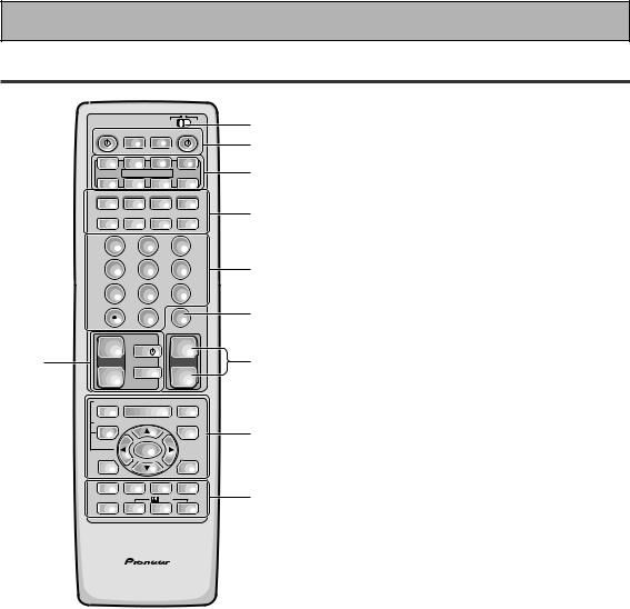
Displays & Controls
Remote Control
|
Î |
|
USE |
SETUP |
1 |
|
|
S0URCE |
|
|
RECEIVER |
||
|
|
MULTI |
SYSTEM |
|
|
2 |
|
|
OPERATION |
OFF |
|
|
|
|
DVD/LD |
TV/SAT |
VCR 1/ |
VCR2 |
3 |
|
|
DVR |
|||||
|
|
MULTI CONTROL |
|
|
||
|
CD |
CD-R/ |
TUNER |
TV CONT |
||
|
TAPE 1 |
|
||||
|
CLASS |
MPX |
BAND |
DIRECT ACCESS |
|
|
|
¶ |
7 |
3 |
8 |
|
4 |
|
- TUNING + |
- STATION + |
||||
|
|
|||||
|
1 |
¡ |
4 |
¢ |
|
|
|
DTV ON/OFF DTV MENU |
- CHANNEL + |
|
|||
|
1 |
2 |
|
3 |
|
|
|
4 |
5 |
|
6 |
|
5 |
|
7 |
8 |
|
9 |
|
6 |
|
GUIDE |
0 |
|
|
EXIT |
|
|
|
|
|
ENTER |
|
|
|
+10 |
|
|
|
DISC |
|
7 |
+ |
TV |
|
+ |
|
8 |
TV VOL |
TV CONTROL |
VOLUME |
||||
|
– |
TV FUNC |
– |
|
|
|
|
REMOTE SETUP |
|
|
|
|
|
|
INPUT |
MENU |
MUTE |
|
||
|
ATT |
|
||||
|
|
|
|
|
|
|
|
SYSTEM SETUP |
+ |
|
|
|
9 |
|
EFFECT/ |
|
FUNCTION |
|||
|
CH SEL |
|
|
|
|
|
|
|
ENTER |
|
|
|
|
|
DIGITAL |
– |
|
SIGNAL |
|
|
|
NR |
|
SELECT |
|
||
|
MIDNIGHT |
MULTI CH |
DSP |
STEREO/ |
10 |
|
|
INPUT |
DIRECT |
||||
|
|
|
/DTS |
|
|
|
|
LIGHT |
THX |
ADVANCED |
STANDARD |
|
|
AV PRE-PROGRAMMED AND LEARNING
REMOTE CONTROL UNIT
1USE/SETUP slide switch
Use to put the remote into receiver SETUP, or receiver USE mode.
2 SOURCE button
Use to turn on the power of your other components after you have recalled or taught the signals to this remote control.
MULTI OPERATION button
Use this button to start the MULTI OPERATION mode. See p. 73 – 74 for how to program and use the MULTI OPERATION mode.
SYSTEM OFF button
This button turns off components in two ways. First, when pressed it will turn off all PIONEER components. Secondly, any component that has programmed into the MULTI OPERATIONS settings will also be turned off (see p. 75).
For example : If you programmed power on for your TV and VCR, pressing the SYSTEM OFF button will turn off these components even if they are not PIONEER products.
 RECEIVER button
Press to turn power of the receiver on or to STANDBY (off).
3MULTI CONTROL buttons
Use these to select a source and the corresponding remote operation mode.
For example, pressing TUNER selects the built in tuner and sets the remote operation to the tuner functions.
4Component Control buttons
Use to control specific components, like a CD player or DVD player, after you have programmed the remote control to do these operations (see p.62– 68) and the remote is put in that operation mode.
[Tuner control]
CLASS – Press repeatedly to switch the preset station classes.
MPX – Press to switch between auto stereo and MONO reception of FM broadcasts. BAND – Press to select AM or FM band. DIRECT ACCESS – Press to activate the direct access tuning mode.
TUNING +/– – Use to manually tune in to radio stations.
STATION +/– – Use to choose programmed radio stations.
5Number buttons
These buttons can perform a variety of different functions depending on the remote operation mode. They are most useful for CD and tuner operations.
6ENTER button
Use for controlling other components only.
7TV CONTROL buttons
The following buttons are used to control the TV only and can be used no matter what function the remote control is set to.
TV  button – Press to turn the power of the TV on/off.
TV FUNC button – Press TV FUNC to select the TV for remote control operation.
TV VOL +/– button – Use to adjust the TV volume.
24

Displays & Controls
8MASTER VOLUME buttons
Use to raise or lower the volume of the receiver.
9INPUT ATT button (when USE mode is selected)
Use to lower the input level of an analog signal that is too powerful, thus causing the sound to distort (the OVERLOAD indicactor will light).
REMOTE SETUP button (when SETUP mode is selected)
Use to customize the remote control functions and the remote control itself. (See “Setting Up the Remote Control to Control Other Components“ starting on p. 58, “Multi Operations“ starting on p. 73.)
MENU button
Use to get the various menus for your DVD, TV or DTV.
MUTE button
Press to mute or restore the volume.
EFFECT/CH SEL (when USE mode is selected) button (see memo on p.44).
EFFECT – Use these buttons to increase or decrease the amount of effect applied in a DSP or Advanced Theater mode. When the amount of effect is increased in a DSP/Advanced Theater mode the characteristics of that mode become stronger and more noticeable. The scale ranges from 10-90 with 70 as the default setting. First turn on the DSP/Advanced Theater you want (by pressing the DSP/ Advanced Theater button until you get the mode) and then increase or decrease the amount of effect.
CH SEL – You may want to adjust the channels when listening to some sound sources. Use this button to select the channel you want to adjust.
SYSTEM SET UP button (when SETUP mode is selected)
Use to set up the speaker and sound systems. For more information see “Setting up for Surround Sound“ starting on p. 28.
FUNCTION button
Press to select a source. The button will cycle through all the possible sources.
5(+)/ (–)/2/3/ENTER buttons
Use to operate the on-screen menu on your TV screen and enter commands when setting up surround sound, speakers levels & settings, and other set up features see p. 28 – 40).
They also can be used to operate DVD players, DTVs and other components after you have input the components preset codes. Specific use of these buttons is described in conjunction with the operations they perform. For more information see each individual section.
DIGITAL NR button
Press to switch Digital NR on or off. (See p. 48)
SIGNAL SELECT button (See p. 45)
Press SIGNAL SELECT repeatedly to select one of the following:
ANALOG – Analog signal.
DIGITAL – Digital signal (DVD/LD, TV/SAT, CD, CD-R/TAPE 1, VCR 1/DVR, VCR 2, VIDEO).
AUTO – This is the default. If there are analog, or digital signals input the receiver automatically selects the best possible signal.
10 MIDNIGHT button (See p. 49)
Switches the MIDNIGHT mode on or off.
MULTI CH INPUT button (See p.51).
Press to switch to multi channel input mode.
DSP button (See p. 43, 44)
Press to select a DSP sound mode. Repeated presses cycle through the diffferent possible DSP modes.
STEREO/DIRECT button (See p. 43 & 52)
Switches the receiver into STEREO mode if it was in a different sound mode (like ADVANCED THEATER) or or toggles between DIRECT and STEREO mode. For more on STEREO mode see p. 52.
DIRECT playback bypasses the tone controls and channel level for the most accurate reproduction of a program source.
LIGHT button
Press to light the remote control buttons.
 /DTS buttons (See p. 41-45)
Press these buttons to put the receiver in the selected sound mode. For more information on these specific sound modes see p. 86 & 87.
PREPARATION
25
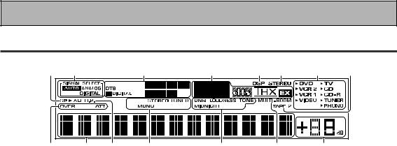
Displays & Controls
Display
All the display information is explained and/or referenced here.
1 |
2 |
|
3 |
4 |
5 |
6 |
7 |
8 |
15 |
14 |
13 |
12 |
11 |
|
10 |
|
9 |
1Speaker indicators
Light to indicate the current speaker system, A and/or B.
2SIGNAL SELECT indicators
Light to indicate the input signal you selected.
ANALOG – Lights when analog signals are assigned.
DIGITAL – Lights when digital audio signals are selected.
AUTO – Lights when the receiver is set to select the input signal automatically.
3Program Format indicator
2DIGITAL – Lights when a source with Dolby Digital signals is played.
DTS – Lights when a source with DTS audio signals is played.
For Dolby Digital or DTS sources: These indicators change according to which channels are active in the source. When all three LS (left surround), S (surround) and RS (right surround) light at the same time it means a SURROUND EX source or a DTS ES source with surround back channels is being used.
L – Left front channel. C – Center channel.
R – Right front channel.
LS – Left surround channel. S – Surround channel (mono). RS – Right surround channel.
LFE – Low Frequency Effects channel.
42/dts mode indicators (See p.42 – 44)
2DIGITAL – Indicates multi channel playback of a Dolby Digital source.
2PRO LOGIC – Lights when Dolby Pro Logic decoding is switched on.
dts – When the 2/dts mode on the receiver is on, this indicator lights to indicate playback of a DTS signal.
THX – Lights when the HOME THX CINEMA mode is selected.
EX – Lights when decoding a Surround EX source.
5DSP indicator (See p.42 – 44)
Light when a DSP or Advanced Theater mode is selected.
6STEREO indicator
Lights when a STEREO mode is selected.
7Source indicators
3 indicator lights at the selecting source.
8TAPE 2 indicator
Lights when the TAPE 2 monitor is on.
9MASTER VOLUME indicator
Displays current volume level.
10MULTI-ROOM indicator
Lights when the Multi-room system is on.
11Sound control indicators
DNR – Lights when the digital NR is on. LOUDNESS – Lights when the Loudness is on. TONE – Lights when the Tone control is on. MIDNIGHT – Lights when the Midnight mode is on.
12Tuner indicators
STEREO – Lights when a FM stereo broadcast is received in the auto stereo mode.
TUNED – Lights when a broadcast is received. MONO – Lights when the tuner is set to receive FM broadcasts with the mono mode selected.
13H.P. (headphones)
Lights when headphones are connected to the PHONES jack (speakers systems A and B both turn off automatically).
14Character display
Shows current mode, status, etc.
15Analog level indicators
OVER – When the source signal is analog, this lights if the signal is in danger of distorting. Press INPUT ATT on the remote control to lower the signal level.
ATT – Lights when INPUT ATT is used to reduce the level of the analog source signal.
26

Initial Setup
On Screen Display
There are a number of possible ways to hook up the receiver to your video components, like a DVD player, and hook up to your receiver to your TV, but some of them will not allow you to use the on-screen display of this unit. To avoid this, you simply need to keep the following rules:
1Always use the same type of video cords to hook up your video components to the receiver as you use to hook up the receiver to your TV. For example, if you use composite video cords to hook up your DVD player to the receiver, use composite video cords to hook up the receiver to your TV. If you use S video cords to hook up your DVD player and the receiver, use S video cords to hook up the receiver to your TV.
2Always make sure your TV is set to the appropriate input channel (for example, video 1).Your TV may have a number of input channels and if you do not select the proper one, you will not be able to use this receiver’s on-screen display, or, in fact see any picture from this receiver at all. If you are unsure how to choose an input channel for your TV, refer to the manual which came with your TV.
SET
UP
27
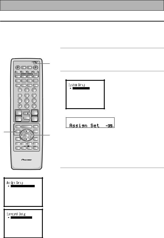
Initial Setup
Setting Up for Surround Sound
To ensure the best possible surround sound, complete the following setup operations. You only need to make these settings once (unless you change the placement of your current speaker system or add new speakers, etc.).
To set up this receiver's home cinema system you can use on-screen displays on your TV or the front panel display on the receiver. Switch on the receiver and your TV, and make sure that the receiver is selected as your TV's video input. You can make the settings with the remote control or the MULTI JOG dial on the front panel.
|
|
|
|
1 |
Set the slide switch to SETUP. |
|
|
|
|
1 |
Also make sure your TV is on and set to the receiver. |
S0URCE |
|
|
RECEIVER |
• When you're done setting up the receiver, remember to |
|
Î |
|
USE SETUP |
|
|
|
|
OPERATION |
OFF |
|
|
set the slide switch back to USE. |
|
MULTI |
SYSTEM |
|
|
|
DVD/LD |
TV/SAT |
VCR 1/ |
VCR2 |
|
|
DVR |
|
|
|||
|
MULTI CONTROL |
|
2 Press the SYSTEM SETUP button. |
||
|
TAPE 1 |
|
|
||
CD |
CD-R/ |
TUNER |
TV CONT |
|
|
|
|
|
|||
CLASS |
MPX |
BAND |
DIRECT ACCESS |
|
|
¶ 7 3 8
3 8
- TUNING + |
|
- STATION + |
1 ¡ 4 ¢ |
||
DTV ON/OFF DTV MENU |
- CHANNEL + |
|
1 |
2 |
3 |
4 |
5 |
6 |
7 |
8 |
9 |
GUIDE |
0 |
EXIT |
|
ENTER |
|
+10 |
|
DISC |
[ As s i gn S e t u p ]
[ S u r r o u n d S e t u p ]
[ F u n c t i o n R en ame ] [ EX I T ]
|
+ |
TV |
|
+ |
|
This SYSTEM SETUP MENU appears on your TV screen. |
|
TV VOL |
TV CONTROL |
VOLUME |
|
|
|
|
– |
TV FUNC |
– |
|
|
|
|
REMOTE SETUP |
|
|
|
|
|
|
INPUT |
MENU |
|
MUTE |
|
|
|
ATT |
|
|
|
||
2 |
SYSTEM SETUP |
+ |
|
|
|
This display appears on the receiver. |
EFFECT/ |
|
FUNCTION |
|
|||
|
CH SEL |
|
|
3 |
|
|
|
|
ENTER |
|
• You can escape from this screen at any time by pressing the |
||
|
DIGITAL |
– |
|
SIGNAL |
||
|
NR |
|
SELECT |
|
SYSTEM SETUP button again. None of the settings you |
|
|
|
MULTI CH |
|
STEREO/ |
|
|
|
MIDNIGHT |
DSP |
|
made will be entered in this case. |
||
|
INPUT |
DIRECT |
|
|||
|
|
/DTS |
|
|||
|
LIGHT |
THX ADVANCED |
STANDARD |
|
|
|
AV PRE-PROGRAMMED AND LEARNING
REMOTE CONTROL UNIT
•If you want to go back one level in the setup process press the RETURN button.
•If don't enter any settings the receiver will revert back to it's previous state after three minutes.
[ D i g i t a l - I n Se l e c t ] [ Mu l t i Ch a n ne l I n ]
[ C ompo n en t - I n Se l e c t ] [ Mu l t i - Ro om ]
[ EX I T ]
[ Sp e a k e r S e t t i n g ] [ C h a n n e l De l a y ]
[ C h a n n e l L e v e l ]
[ C r o s s o ve r Ne t wo r k ] [ B a s s Pea k Le v e l ]
[ D - R a n g e Co n t r o l ] [ EX I T ]
28
3Press the 5 or arrow buttons (or turn the
MULTI JOG dial) to move the hand to the second tier of setup modes and choose the one you want. Then press the ENTER button
(or the MULTI JOG dial).
There are three second tier setup modes: Assign Setup, Surround Setup and Rename. The first of these, Assign Setup, is for telling the receiver which components are hooked up to which terminals and how they are connected as well as setting up the optional MULTI ROOM feature, which is only used if you want the receiver to power systems in more than one room. In the Assign Setup menu you must make the Digital In adjustments if you didn't follow the default settings when you hooked up your DVD/LD player.
We suggest you start with Digital In and adjust and make all the necessary adjustments here and then move on to the other entries in this menu and decide if you need to make these adjustments. It is likely you will not need to bother with any of the other things on this menu.
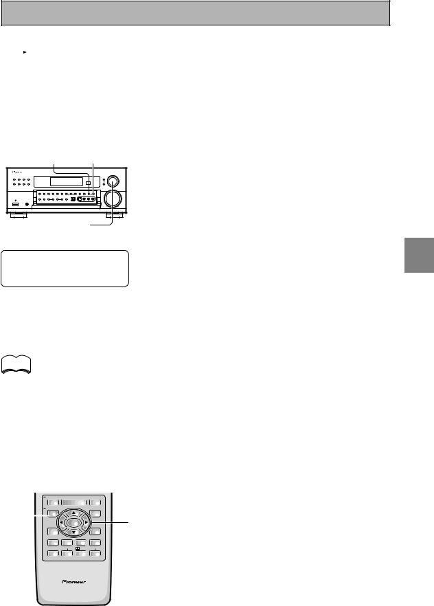
Initial Setup
Fu n c t i on Re n ame |
|
|
DVD / L D |
[ DVD / L D |
] |
VCR2 |
[ VCR2 |
] |
VCR1 |
[ VCR1 / DVR |
] |
V I DEO |
[ V I DEO |
] |
PHONO |
[ PHONO |
] |
CD - R |
[ CD - R / TAPE1 ] |
|
CD |
[ CD |
] |
TV / SAT |
[ TV / SAT |
] |
[ EX I T ] |
|
|
|
|
|
RETURN |
SETUP |
MULTI JOG
(Turn to select / Push to enter)
Next move on to the SURROUND SETUP menu and make all the necessary settings. It is essential you make these settings in order to get good surround sound .
The last set up menu, RENAME, lets you customize the receiver to match your home system.
The sound set up modes explained here in a little more detail. The order follows that of the SYSTEM SETUP menu.
ASSIGN SETUP:
Digital In Select (See p.30)
In order to use your digital components you must match the numbered digital input settings with the numbered digital jacks used by your digital components.
Multi Channel In (See p.31)
This is for hooking up a multi channel external decoder that may give you higher quality when decoding discs. This feature lets you select adjustable to non-adjustable sound.
Component-In Select (See p.32)
In order to use component video connections you must tell the receiver which components are hooked to which terminals.
Multi Room (See p.81)
This receiver can power different systems set up in separate
RETURN button: |
|
|
|
|
|
rooms. |
||||||||
Press to move back one step in the |
|
|||||||||||||
|
SURROUND SETUP: |
|||||||||||||
SETUP process. |
|
|
|
|
|
|
|
|
||||||
|
|
|
|
|
|
|
|
Speaker Setting (See p.33 – 34) |
||||||
|
|
|
|
|
|
|
|
|
|
|
|
|
||
|
|
|
|
|
|
|
|
|
|
|
|
|
Use to specify the type and number of speakers you connected. |
|
|
|
|
|
|
|
|
|
|
|
|
|
|
Channel Delay (See p.35) |
|
|
|
|
|
|
|
|
|
|
|
|
|
|
Adding a slight delay to some speakers enhances sound |
|
|
|
|
|
|
|
|
|
|
|
|
|
|
separation and is particularly important for achieving a surround |
|
|
|
|
|
|
|
|
|
|
|
|
|
|
sound effect. You need to figure out the distance from your |
|
memo |
|
|
|
|
|
|
|
|
|
|
|
listening position to your speakers to add the proper delay. |
||
|
|
|
|
|
|
|
|
|
|
|
Channel Level (See p.36 – 37) |
|||
|
|
|
|
|
|
|
|
|
|
|
|
|
||
After you complete one of the |
|
Use to balance the volumes of your different speakers. |
||||||||||||
|
Crossover Network (See p.38) |
|||||||||||||
System Setup menus and return to |
||||||||||||||
the basic System Setup screen the |
|
This feature lets you select which bass frequencies will be sent |
||||||||||||
receiver automatically moves the |
|
to the subwoofer or front speakers. |
||||||||||||
cursor to the next System Setup |
|
Bass Peak Level (See p.39) |
||||||||||||
menu. For example, if you've |
|
Dolby Digital and DTS audio sources include ultra-low bass |
||||||||||||
completed Speaker Settings and |
|
|||||||||||||
|
tones. Set the bass peak level as needed to prevent the ultra- |
|||||||||||||
returned to the basic System Setup |
||||||||||||||
low bass tones from distorting the sound from the speakers. |
||||||||||||||
screen, Channel Delay will be |
|
Dynamic Range Control (See p.40) |
||||||||||||
selected automatically. You can |
|
|||||||||||||
|
This feature makes possible excellent surround sound effects |
|||||||||||||
notice this on your TV screen. |
|
|||||||||||||
|
when listening to Dolby Digital sources at low volumes. |
|||||||||||||
|
|
|
|
|
|
|
|
|
|
|
|
|
||
|
|
|
INPUT |
|
|
|
|
|
|
|
|
RENAME (See p.69 – 70) |
||
|
|
REMOTE SETUP |
|
MENU |
|
|
MUTE |
|
|
|||||
|
|
|
ATT |
|
|
|
|
This feature lets you rename specific "functions," which in this |
||||||
4 |
|
|
EFFECT/ |
|
|
|
|
|
FUNCTION |
|
||||
|
SYSTEM SETUP |
+ |
|
|
|
|
|
|
|
|||||
|
|
|
CH SEL |
|
|
|
|
|
4 |
case stands for components like DVD/LD, VCR 1 , etc. This is a |
||||
(to exit |
|
|
|
|
ENTER |
|
|
|||||||
|
DIGITAL |
|
– |
|
|
SIGNAL |
useful feature for matching the remote control and receiver |
|||||||
SYSTEM |
|
NR |
|
|
|
SELECT |
|
display exactly with your home setup. |
||||||
|
|
|
|
|
|
|
|
|
|
|
||||
SETUP) |
|
MIDNIGHT |
MULTI CH |
/DTS |
STEREO/ |
|
||||||||
|
|
|
INPUT |
DSP |
DIRECT |
|
|
|||||||
|
|
|
|
|
|
|
|
|
||||||
|
|
|
|
|
|
|
|
|
|
|
|
4 Press ENTER. Go on to the next page to |
||
|
|
|
LIGHT |
THX ADVANCED |
STANDARD |
|
||||||||
|
|
|
|
|
|
|
|
|
|
|
|
|
||
|
|
|
|
|
|
|
|
|
|
|
|
|
start the set up. |
|
|
|
|
AV PRE-PROGRAMMED AND LEARNING |
|
If you don't want to make any settings go can exit this setup. |
|||||||||
|
|
|
|
REMOTE CONTROL UNIT |
|
|
|
To exit the System Setup menu and on-screen display press |
||||||
|
|
|
|
|
|
|
|
|
|
|
|
|
||
SYSTEM SETUP button again.
SET UP
29
 Loading...