


|
TV |
|
FUNC |
VOL |
VOL |
ORDER NO.
RRV1897
AUDIO/VIDEO MULTI-CHANNEL RECEIVER
VSX-D607S
THIS MANUAL IS APPLICABLE TO THE FOLLOWING MODEL(S) AND TYPE(S).
Type |
Model |
Power Requirement |
The voltage can be converted by the |
|
VSX-D607S |
following method. |
|||
|
||||
|
|
|||
KUXJI |
|
AC120V |
|
|
|
|
|
|
|
KCXJI |
|
AC120V |
|
|
SDXJI |
|
AC110V/120-127V/220V/240V |
With the voltage selector |
CONTENTS
1. SAFETY INFORMATION ...................................... |
2 |
7. GENERAL INFORMATION ................................ |
53 |
2. EXPLODED VIEWS AND PARTS LIST ................ |
3 |
7.1 DISPLAY ....................................................... |
53 |
3. SCHEMATIC DIAGRAM ....................................... |
8 |
7.2 PCB LOCATION ........................................... |
55 |
4. PCB CONNECTION DIAGRAM .......................... |
32 |
7.3 BLOCK DIAGRAM ........................................ |
56 |
5. PCB PARTS LIST ............................................... |
44 |
7.4 REMOTE CONTROL UNIT .......................... |
58 |
6. ADJUSTMENT .................................................... |
51 |
[CU-VSX128 (AXD7153)] |
|
|
|
8. PANEL FACILITIES AND SPECIFICATIONS .... |
62 |
PIONEER ELECTRONIC CORPORATION 4-1, Meguro 1-Chome, Meguro-ku, Tokyo 153-8654, Japan PIONEER ELECTRONICS SERVICE, INC. P.O. Box 1760, Long Beach, CA 90801-1760, U.S.A.
PIONEER ELECTRONIC (EUROPE) N.V. Haven 1087, Keetberglaan 1, 9120 Melsele, Belgium
PIONEER ELECTRONICS ASIACENTRE PTE. LTD. 501 Orchard Road, #10-00 Lane Crawford Place, Singapore 0923 c PIONEER ELECTRONIC CORPORATION 1998
T - IZK JAN. 1998 Printed in Japan
VSX-D607S
1. SAFETY INFORMATION
This service manual is intended for qualified service technicians ; it is not meant for the casual do-it- yourselfer. Qualified technicians have the necessary test equipment and tools, and have been trained to properly and safely repair complex products such as those covered by this manual.
Improperly performed repairs can adversely affect the safety and reliability of the product and may void the warranty. If you are not qualified to perform the repair of this product properly and safely, you should not risk trying to do so and refer the repair to a qualified service technician.
WARNING
Lead in solder used in this product is listed by the California Health and Welfare agency as a known reproductive toxicant which may cause birth defects or other reproductive harm (California Health & Safety Code, Section 25249.5).
When servicing or handling circuit boards and other components which contain lead in solder, avoid unprotected skin contact with the solder. Also, when soldering do not inhale any smoke or fumes produced.
NOTICE
(FOR CANADIAN MODEL ONLY)
Fuse symbols  (fast operating fuse) and/or
  (slow operating fuse) on PCB indicate that replacement parts must be of identical designation.
REMARQUE
(POUR MODÈLE CANADIEN SEULEMENT)
Les symboles de fusible  (fusible de type rapide) et/ou
  (fusible de type lent) sur CCI indiquent que les pièces de remplacement doivent avoir la même désignation.
(FOR USA MODEL ONLY)
1. SAFETY PRECAUTIONS
The following check should be performed for the continued protection of the customer and service technician.
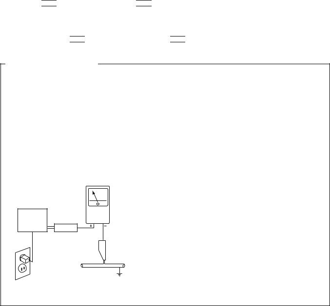
LEAKAGE CURRENT CHECK
Measure leakage current to a known earth ground (water pipe, conduit, etc.) by connecting a leakage current tester such as Simpson Model 229-2 or equivalent between the earth ground and all exposed metal parts of the appliance (input/output terminals, screwheads, metal overlays, control shaft, etc.). Plug the AC line cord of the appliance directly into a 120V AC 60Hz outlet and turn the AC power switch on. Any current measured must not exceed 0.5mA.
|
|
Reading should |
|
Leakage |
not be above |
Device |
current |
0.5mA |
under |
tester |
|
test |
|
|
Test all |
|
|
exposed metal |
|
|
surfaces |
|
|
Also test with |
|
|
plug reversed |
|
Earth |
(Using AC adapter |
|
ground |
plug as required) |
|
|
AC Leakage Test
ANY MEASUREMENTS NOT WITHIN THE LIMITS OUTLINED ABOVE ARE INDICATIVE OF A POTENTIAL SHOCK HAZARD AND MUST BE CORRECTED BEFORE RETURNING THE APPLIANCE TO THE CUSTOMER.
2. PRODUCT SAFETY NOTICE
Many electrical and mechanical parts in the appliance have special safety related characteristics. These are often not evident from visual inspection nor the protection afforded by them necessarily can be obtained by using replacement components rated for voltage, wattage, etc. Replacement parts which have these special safety characteristics are identified in this Service Manual.
Electrical components having such features are identified by marking with a  on the schematics and on the parts list in this Service Manual.
The use of a substitute replacement component which does not have the same safety characteristics as the PIONEER recommended replacement one, shown in the parts list in this Service Manual, may create shock, fire, or other hazards.
Product Safety is continuously under review and new instructions are issued from time to time. For the latest information, always consult the current PIONEER Service Manual. A subscription to, or additional copies of, PIONEER Service Manual may be obtained at a nominal charge from PIONEER.
2
VSX-D607S
2. EXPLODED VIEWS AND PARTS LIST
∙
∙The  mark found on some component parts indicates the importance of the safety factor of the part. Therefore, when replacing, be sure to use parts of identical designation.
∙Screws adjacent to  mark on the product are used for disassembly.
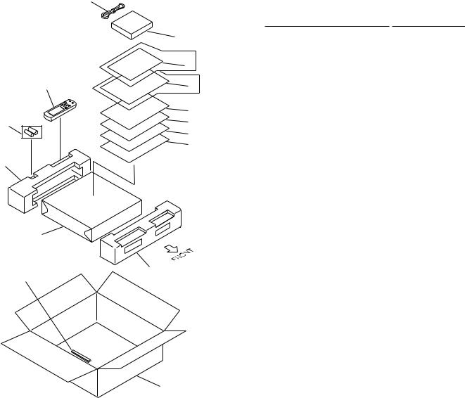
2.1PACKINGParts marked by "NSP" are generally unavailable because they are not in our Master Spare Parts List.NOTES:
2 |
|
(1) PACKING PARTS LIST |
|
||
|
|
|
|||
|
|
Mark |
No. |
Description |
Part No. |
|
6 |
NSP |
1 |
Dry Cell Battery (LR6,AA) |
AEX1007 |
|
SDXJI Type Only |
|
2 |
FM Antenna |
ADH7004 |
|
|
3 |
Operating Instructions |
See Contrast table (2) |
|
|
|
|
|||
|
15 |
|
4 |
Sub Instruction Manual |
ARH7015 |
Refer to |
|
|
(Remote Control Unit)(English) |
||
|
|
|
|||
"7.4 REMOTE CONTROL UNIT". |
|
|
|
|
|
9 |
8 |
NSP |
5 |
Warranty Card |
See Contrast table (2) |
|
KCXJI Type Only |
|
6 |
AM Loop Antenna |
ATB7009 |
|
|
7 |
Sub Instruction Manual |
ARH7030 |
|
|
5 |
|
|||
|
|
|
(AC-3) (English) |
|
|
1 |
7 |
|
8 |
Operating Instructions |
See Contrast table (2) |
4 |
|
|
(French) |
|
|
|
|
|
|
||
|
|
|
|
|
|
|
3 |
|
9 |
Remote Control Unit |
AXD7153 |
|
|
|
|
(CU-VSX128) |
|
11 |
|
|
10 |
Front Pad |
AHA7137 |
|
|
|
11 |
Rear Pad |
AHA7140 |
|
|
|
12 |
Packing Case |
See Contrast table (2) |
|
|
|
13 |
Packing Sheet |
AHG7010 |
|
|
|
14 |
Sub Pad B |
AHB7027 |
|
|
|
15 |
Caution 220V Label |
See Contrast table (2) |
13 |
|
|
|
|
|
14 |
10 |
|
12
(2) CONTRAST TABLE
VSX-D607S/KUXJI, KCXJI and SDXJI are constructed the same except for the following :
|
|
|
|
Part No. |
|
|
Mark |
No. |
Symbol and Description |
|
|
|
Remarks |
VSX-D607S |
VSX-D607S |
VSX-D607S |
||||
|
|
|
/KUXJI |
/KCXJI |
/SDXJI |
|
|
|
|
|
|
|
|
|
3 |
Operating Instructions (English) |
ARB7140 |
ARB7140 |
Not used |
|
|
3 |
Operating Instructions (English/Chinese/Spanish) |
Not used |
Not used |
ARE7155 |
|
NSP |
5 |
Warranty Card |
ARY1051 |
ARY1075 |
ARY1077 |
|
|
8 |
Operating Instructions (French) |
Not used |
ARC7189 |
Not used |
|
|
12 |
Packing Case |
AHD7570 |
AHD7570 |
AHD7571 |
|
|
15 |
Caution 220V Label |
Not used |
Not used |
ARR1003 |
|
|
|
|
|
|
|
|
3
VSX-D607S
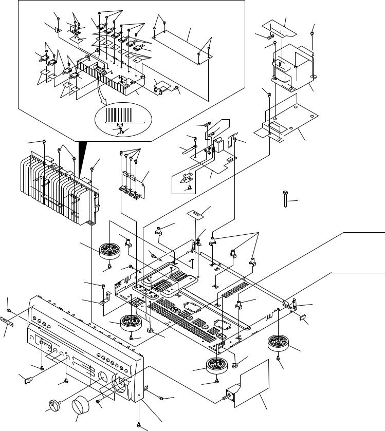
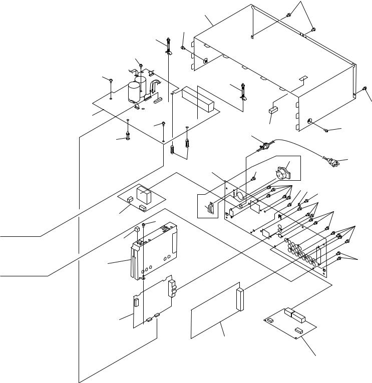
2.2 EXTERIOR
50 |
50 |
14 |
|
45 |
50 |
|
|
3 |
|
|
|
|
|
|
|||
|
|
|
|
|
|
|
||
19 |
27 |
27 |
|
|
45 |
5 |
|
|
|
|
|
|
|
|
|
||
|
2 |
|
|
|
|
|
|
|
|
13 |
|
|
|
|
50 |
16 |
|
45 |
|
32 |
|
|
14 |
|
|
|
|
13 |
33 |
|
|
|
|
56 |
|
14 |
|
|
13 |
|
|
|||
45 |
|
|
|
|
|
|||
|
|
|
|
|
|
|||
|
|
|
|
|
33 |
|
|
|
|
|
14 |
|
|
11 |
|
|
|
|
|
|
|
|
|
|
|
|
33 |
|
|
|
|
|
|
|
50 |
|
|
|
|
|
|
|
|
|
|
33 |
|
|
|
25 |
50 |
|
|
|
|
|
|
|
|
|
|
|
|
|
|
|
|
|
|
|
SDXJI Type |
|
|
|
|
|
|
|
|
Only |
|
|
|
43 |
50 |
|
17 |
|
64 |
|
|
|
|
51 |
|
|
||
|
|
|
|
|
|
|
||
|
|
|
|
|
|
|
|
|
48 |
48 |
|
|
|
50 |
36 |
|
51 |
|
|
|
|
|
||||
|
|
|
|
|
|
|
||
|
|
|
48 |
|
|
|
|
|
|
|
|
|
|
4 |
|
|
|
|
|
|
|
|
|
57 |
7 |
|
|
|
|
|
|
|
58 |
|
|
|
|
|
|
|
|
|
59 |
|
|
|
|
|
|
|
34 |
30 |
|
|
|
|
|
|
|
|
34 |
|
|
|
|
|
34 |
|
|
|
|
|
|
|
|
|
|
|
|
|
|
20 |
|
|
|
50 |
|
|
|
|
|
|
|
|
|
|
|
|
|
|
|
50 |
50 |
|
|
|
|
|
|
|
|
|
|
|
|
|
|
50 |
|
|
|
|
|
|
|
55 |
46 |
|
|
|
|
|
|
34 |
|
|
|
|
|
|
|
||
|
|
|
21 |
|
|
|
|
|
42 |
|
|
|
|
50 |
60 |
|
|
|
|
|
|
|
|
|
|
|
|
|
|
|
|
|
|
|
60 |
50 |
|
|
|
|
|
|
|
|
39 |
|
|
|
|
|
21 |
|
50 |
50 |
|
|
|
|
50 |
|
|
|
|
|
|
|
|
|
55 |
|
|
40 |
|
|
50 |
|
|
|
|
9 |
|
38 |
|
|
|
|
Refer to |
|
|
50 |
"2.3 FRONT PANEL SECTION". |
|
56
15
41
53
22
61
20
4
VSX-D607S
50
24
50
31
51
51
31
50
1
51 |
28 |
50 |
|
35 |
|
29 |
|
|
29 |
62 |
18 |
|
|
|
23 |
50 |
SDXJI Type |
|
|
|
|
50 |
Only |
|
50 37 |
|
|
|
|
|
|
54 |
63 |
|
50 |
|
|
50 |
10 |
|
51 |
50 |
|
44
50
26
12
6
8
5
VSX-D607S
(1) EXTERIOR PARTS LIST
Mark No. |
Description |
|
Part No. |
Mark No. |
Description |
|
Part No. |
||
|
|
|
|
|
|
|
|
|
|
|
1 |
INPUT Assy |
See Contrast table (2) |
NSP |
2 |
MOS FET Assy |
AWZ8497 |
|
3 |
TRANS Assy |
AWZ8496 |
|
4 |
REG.1 Assy |
AWZ8507 |
|
5 |
R/C AMP Assy |
AWZ8504 |
|
6 |
FM/AM TUNER Module |
See Contrast table (2) |
NSP |
7 |
PRIMARY Assy |
See Contrast table (2) |
|
8 |
VIDEO/SR Assy |
AWZ8509 |
|
9 |
VOLUME Assy |
AWZ8047 |
|
10 |
R/C SPEAKER Assy |
See Contrast table (2) |
|
11 |
REG.2 Assy |
AWZ8498 |
|
12 |
DOLBY DIGITAL Assy |
AWX7042 |
|
13 |
Transistor(Q3,Q4,Q7,Q8,Q10) |
2SA1962 |
|
14 |
Transistor(Q1,Q2,Q5,Q6,Q9) |
2SC5242 |
|
15 |
Power Transformer |
See Contrast table (2) |
|
16 |
Fuse (FU3-FU5 : 1.6A) |
REK1077 |
|
17 |
Fuse (FU1) |
See Contrast table (2) |
|
18 |
AC Power Cord |
See Contrast table (2) |
|
19 |
FET Plate |
ANG7124 |
|
20 |
Insulator |
AMR7198 |
|
21 |
Insulator |
PNW2766 |
|
22 |
Chassis |
ANA7052 |
|
23 |
Rear Panel |
See Contrast table (2) |
|
24 |
Bonnet Case |
ANE7136 |
|
25 |
Radiator |
ANH7050 |
|
26 |
Shield Case |
ANK7037 |
NSP |
27 |
Bushing |
AEC1402 |
NSP |
28 |
Cushion |
AEB7076 |
|
29 |
PCB Support |
AEC1581 |
|
30 |
PCB Support |
AEC7006 |
|
31 |
PCB Support |
AEC7056 |
|
32 |
Sheet |
AEE1028 |
|
33 |
Sheet |
AEE7010 |
|
34 |
PCB Mold |
AMR2533 |
|
35 |
Cord Stopper |
See Contrast table (2) |
NSP |
36 |
Clamper |
RNE1277 |
|
37 |
Washer |
AEC7110 |
|
38 |
Round Knob L |
AAB7082 |
|
39 |
Round Knob S |
AAB7106 |
|
40 |
Jog Knob |
AAB7048 |
|
41 |
Trans Frame |
ANG7140 |
|
42 |
Name Plate |
PAM1755 |
NSP |
43 |
Cord with Plug (J105) |
DE012CD0 |
|
44 |
Cushion Rubber |
AEB7081 |
|
45 |
Screw |
ABA1037 |
|
46 |
PCB Stopper |
ANG7136 |
|
47 |
.• • • • • |
|
|
48 |
Screw |
ABA7019 |
|
49 |
• • • • • |
|
|
50 |
Screw |
BBZ30P080FZK |
|
51 |
Screw |
BBZ30P180FMC |
|
52 |
• • • • • |
|
NSP |
53 |
Binder |
ZCA-BK1 |
|
54 |
Screw |
ABA7035 |
|
55 |
Screw |
ABA-298 |
|
56 |
Screw |
ABA1147 |
|
57 |
Barrier |
See Contrast table (2) |
|
58 |
Push Rivet |
See Contrast table (2) |
|
59 |
Spacer |
AEE7024 |
NSP |
60 |
Spacer |
AEB7092 |
NSP |
61 |
Spacer B |
AEB7086 |
|
62 |
Voltage Selector (S1) |
See Contrast table (2) |
|
63 |
Voltage Selector (S2) |
See Contrast table (2) |
|
64 |
Fuse (FU2 : 3.15A) |
See Contrast table (2) |
(2) CONTRAST TABLE
VSX-D607S/KUXJI, KCXJI and SDXJI are constructed the same except for the following :
|
|
|
|
Part No. |
|
|
Mark |
No. |
Symbol and Description |
|
|
|
Remarks |
VSX-D607S |
VSX-D607S |
VSX-D607S |
||||
|
|
|
/KUXJI |
/KCXJI |
/SDXJI |
|
|
|
|
|
|
|
|
|
1 |
INPUT Assy |
AWX7148 |
AWX7148 |
AWX7149 |
|
|
6 |
FM/AM TUNER Module |
AXQ7219 |
AXQ7219 |
AXQ3112 |
|
NSP |
7 |
PRIMARY Assy |
AWZ8865 |
AWZ8865 |
AWZ8866 |
|
|
10 |
R/C SPEAKER Assy |
AWZ8505 |
AWZ8505 |
AWZ8613 |
|
|
15 |
Power transformer (AC120V) |
ATS7161 |
ATS7161 |
Not used |
|
|
15 |
Power transformer (AC110V/120-127V/220V/240V) |
Not used |
Not used |
ATS7163 |
|
|
17 |
Fuse (FU1 : 6.3A) |
REK1085 |
REK1085 |
Not used |
|
|
17 |
Fuse (FU1 : 3.15A) |
Not used |
Not used |
REK1064 |
|
|
18 |
AC Power Cord |
PDG1015 |
PDG1015 |
ADG1157 |
|
|
23 |
Rear Panel |
ANC7650 |
ANC7650 |
ANC7652 |
|
|
35 |
Cord Stopper |
CM-22C |
CM-22C |
CM-22B |
|
|
57 |
Barrier |
Not used |
Not used |
AEC7137 |
|
|
58 |
Push Rivet |
Not used |
Not used |
AEC7138 |
|
|
62 |
Voltage Selector (S1) |
Not used |
Not used |
AKX-507 |
|
|
63 |
Voltage Selector (S2) |
Not used |
Not used |
AKX1004 |
|
|
64 |
Fuse (FU2 : 3.15A) |
Not used |
Not used |
REK1064 |
|
|
|
|
|
|
|
|
6
VSX-D607S
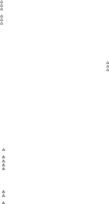
2.3 FRONT PANEL SECTION
|
15 |
|
|
|
3 |
15 |
15 |
|
|
15 |
|
|
|
|
15 |
|
|
|
15 |
9 |
|
|
|
5 |
15 |
|
15 |
|
|
|
|
|
1 |
|
15 |
|
|
15 |
|
|
15 |
|
15 |
|
|
14 |
|
|
|
|
14 |
|
11 |
|
4 |
|
|
2 |
|
|
|
|
8 |
7
6
12 |
13 |
16 |
10 |
|
∙ FRONT PANEL SECTION PARTS LIST
Mark |
No. |
Description |
|
Part No. |
Mark No. |
Description |
|
Part No. |
|
NSP |
1 |
POWER SWITCH Assy |
|
AWZ8501 |
|
11 |
FL Filter |
|
AAK7294 |
NSP |
2 |
FRONT INPUT Assy |
|
AWZ8502 |
12 |
Sub Panel |
|
AAP7042 |
|
|
3 |
FL/U-COM Assy |
|
AWZ8043 |
13 |
Front Panel |
|
AMB7501 |
|
NSP |
4 |
Housing 5P Shield (J27) |
|
ADX1653 |
14 |
Screw |
|
ABA7009 |
|
|
5 |
Power Button |
|
AAD7325 |
15 |
Screw |
|
BPZ30P080FMC |
|
|
6 |
Tuner Button |
|
AAD7326 |
16 |
Screw |
|
BBZ30P080FZK |
|
|
7 |
Input Button |
|
AAD7327 |
|
|
|
|
|
|
8 |
Func. Button |
|
AAD7328 |
|
|
|
|
|
|
9 |
SFC Button |
|
AAD7329 |
|
|
|
|
|
|
10 |
FL Panel |
|
AAK7295 |
|
|
|
|
|
7
|
1 |
|
2 |
|
3 |
|
4 |
|
|
|
|
|
|
VSX-D607S
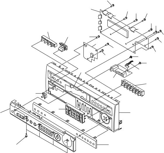
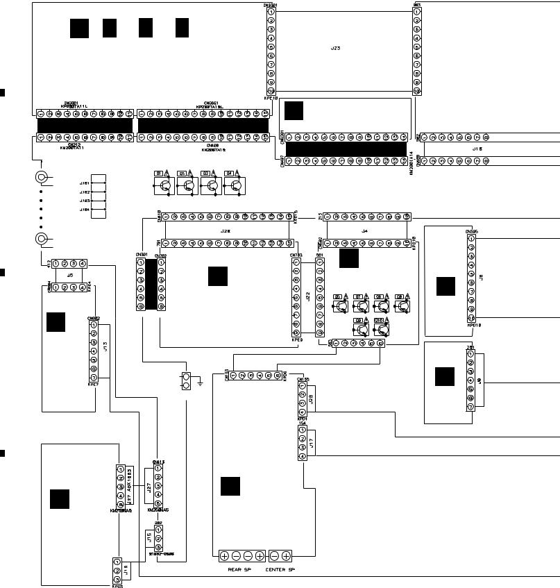
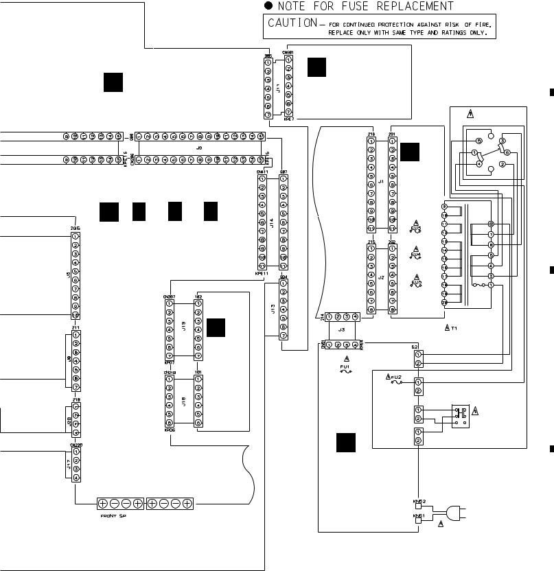
3. SCHEMATIC DIAGRAM
3.1 OVERALL CONNECTION DIAGRAM
Note : When ordering service parts, be sure to refer to "EXPLODED VIEWS and PARTS LIST" or "PCB PARTS LIST".
A
H ( H 1/3, H 2/3, H 3/3 )
DOLBY DIGITAL ASSY (AWX7042)
FM/AM TUNER MODULE O (AXQ7219:KUXJI,KCXJI)
(AXQ3112:SDXJI)
B
L
VIDEO/SR
ASSY
C (AWZ8509)
F |
CN1993 |
|
FRONT INPUT
ASSY
(AWZ8502)
D
CN1992
|
I |
K |
|
|
R/C AMP ASSY |
E |
|
|
|
||
VOLUME ASSY |
(AWZ8504) |
||
|
|||
|
(AWZ8047) |
|
MOS FET |
KM200TA6 KP200TA6L |
|
|
|
|
|
ASSY |
|
|
|
|
|
|
|
|
(AWZ8497) |
|
|
J16 |
|
J165 |
J16 |
|
N |
DE012CD0 |
|
||
|
|
|
|
AKC-082 |
|
|
REG.2 |
|
|
|
ASSY |
|
|
|
(AWZ8498) |
J
R/C SPEAKER ASSY (AWZ8505:KUXJI,KCXJI) (AWZ8613:SDXJI)
8
|
1 |
|
2 |
|
3 |
|
4 |
|
|
|
|
|
|
||||
|
|
|
|
|
|
5 |
|
6 |
|
7 |
|
8 |
|
|
|
|
|
|
VSX-D607S
A
A
FL/U-COM ASSY (AWZ8043)
C ( C 1/3, C 2/3, C 3/3 )
INPUT ASSY (AWX7148:KUXJI,KCXJI) (AWX7149:SDXJI)
G
REG.1
ASSY (AWZ8507)
INPUT ASSY
FL/U-COM ASSY
B
POWER SWITCH ASSY (AWZ8501)
|
SDXJI ONLY |
|
|
S1 |
|
|
VOLTAGE |
|
|
SELECTOR |
|
|
240V |
|
D |
120– |
|
127V |
||
110V |
||
TRANS |
220V |
|
ASSY |
||
B |
(AWZ8496)
INPUT
ASSY
REK1077 1.6A 125V
REK1077 1.6A 125V
REK1077 1.6A 125V
POWER
TRANSFORMER
ATS7161 (KUXJI,KCXJI)
ATS7163 (SDXJI)
C
REK1085 |
56 |
|
6.3A 125V |
REK1064 |
|
(KUXJI,KCXJI) |
|
|
REK1064 |
3.15A 250V |
|
3.15A 250V |
57 |
|
(SDXJI) |
|
|
|
|
|
|
|
S2 |
|
|
VOLTAGE |
|
55 |
SELECTOR |
M |
|
PRIMARY ASSY |
AC POWER CORD |
(AWZ8865:KUXJI,KCXJI) |
KUXJI and KCXJI : |
(AWZ8866:SDXJI) |
PDG1015 |
AC120V 60Hz |
|
|
SDXJI : ADG1157 |
|
AC110V/120-127V/220V/240V |
|
50/60HZ |
LIVE |
|
NEUTRAL |
|
D
9
|
5 |
|
6 |
|
7 |
|
8 |
|
|
|
|
|
|
||||
|
|
|
|
|

|
1 |
|
2 |
|
3 |
|
|
|
|
|
VSX-D607S
3.2 FL/U-COM AND POWER SWITCH ASSEMBLIES
C 2/3 CN206
A
B
L CN802
C |
CN9301 |
|
|
||
|
|
2/3 |
|
|
|
|
|
H |
|
|
|
|
|
|
POWER SWITCH ASSY
B (AWZ8501)
D
10 A 
 B
B
POWER SWITCH ASSY
S981 : DSP MODE
S982 : POWER
S983 : DOLBY PRO LOGIC
S984 : LOUDNESS
S985 : VIDEO
S986 : INPUT MODE
4
C 1/3 CN409
|
1 |
|
2 |
|
3 |
|
4 |
|
|
|
|
|
|
||||
|
|
|
|
|
|
5 |
|
6 |
|
7 |
|
8 |
|
|
|
|
|
|
VSX-D607S
 : AUDIO SIGNAL ROUTE
A
|
A |
FL/U-COM ASSY |
|
|
|
|
(AWZ8043) |
|
|
|
|
|
|
|
|
|
B |
|
|
|
|
|
CN411 |
BASS |
TREBLE |
|
|
|
C 1/3 |
|
|
|
|
||
|
|
BALANCE |
|
|
|
|
|
|
|
|
C |
|
|
FL/U-COM ASSY |
|
|
|
|
|
S901 |
: RESET |
S914 |
: FM/AM |
|
|
S903 |
: SELECT |
S915 |
: MEMORY |
|
|
S904 |
: ENTER |
S916 |
: MPX |
|
|
S905 |
: TAPE2 |
S918 |
: DIRECT |
|
|
S906 |
: CD |
S919 |
: RETURN |
|
|
S907 |
: TUNER |
S920 |
: SPEAKERS B |
|
|
S908 |
: PHONO |
S921 |
: SPEAKERS A |
|
|
S909 |
: VCR/TAPE1 |
S922 |
: MULTI JOG |
|
|
S910 |
: DVD/TV |
VR1901 : BASS ( / ) |
|
|
|
S911 |
: LD/SAT |
VR1902 : TREBLE ( / ) |
|
|
|
S913 |
: CLASS |
VR1903 : BALANCE (L/R) |
|
|
|
|
|
|
D |
|
|
|
7 |
|
A 11 |
5 |
6 |
|
|
8 |
|
|
1 |
|
2 |
|
3 |
|
4 |
|
|
|
|
|
|
VSX-D607S
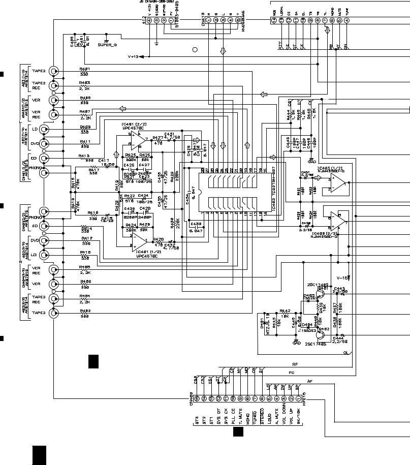
3.3 INPUT ASSY (1/3)
|
L |
CN804 |
|
|
F |
CN1993 |
|
CN6201 |
||
O |
||||||||||
|
|
|
|
|
||||||
|
|
|
|
|
|
|
|
|
|
|
A
ADG [J19 (CN207) 5 pin]
(REC)
(T)
IN)-(F
(T)
|
|
|
VCR OUT |
|
(P) |
(T) |
IN)-(F |
|
|
|
|
B |
|
|
|
(P) |
|
|
(REC) |
|
|
|
FUNCTION SW |
C |
|
|
|
C 1/3 |
INPUT ASSY |
|
|
(AWX7148:KUXJI,KCXJI) |
|
|
|
|
(AWX7149:SDXJI) |
|
|
D |
|
|
|
|
|
|
A J10 |
12 C 1/3
|
1 |
|
2 |
|
3 |
|
4 |
|
|
|
|
|
|
||||
|
|
|
|
|
|
5 |
|
6 |
|
|
|
|
A J14
7 |
|
8 |
|
|
|
VSX-D607S
: AUDIO SIGNAL ROUTE
(SL) : AUDIO SIGNAL ROUTE (REAR)
(C) : AUDIO SIGNAL ROUTE (CENTER)
(T) |
: AUDIO SIGNAL ROUTE (TUNER) |
A |
|
(P) |
: AUDIO SIGNAL ROUTE (PHONO) |
||
|
|||
(REC) |
: AUDIO SIGNAL ROUTE (REC) |
|
|
(F-IN) |
: AUDIO SIGNAL ROUTE (F.IN) |
|
|
CN9661 |
(SL) |
3/3 |
H |
|
|
B |
(C) |
|
(SL)
 (C)
(C)
(SL)
(SL) 
(SL)
I J20
C
|
(C) |
|
|
(C) |
|
(C) |
|
|
|
C 3/3 |
D |
(C) |
|
C 1/3 13
|
5 |
|
6 |
|
7 |
|
8 |
|
|
|
|
|
|
||||
|
|
|
|
|
|
1 |
|
2 |
|
3 |
|
4 |
|
|
|
|
|
|
VSX-D607S
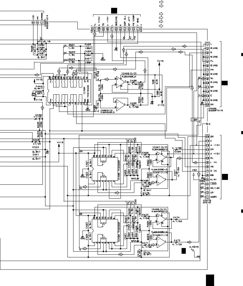
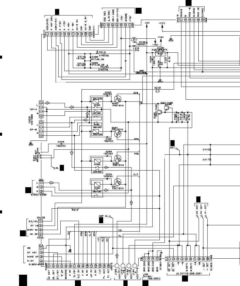
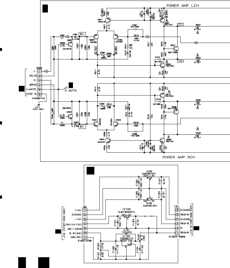
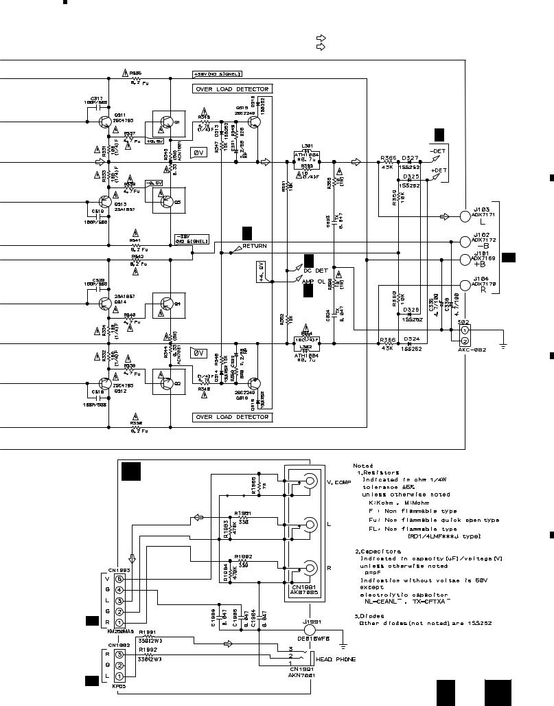
3.4 INPUT (2/3), TRANS AND MOS FET ASSEMBLIES
G J18
H 1/3 CN9801 |
G J19 |
A
B
C
D
FCN1992 |
|
C 2/3 |
J15 |
(H.P) |
|
|
|
|
|
|
(H.P) |
J17 |
|
C 3/3 |
|
|
J |
|
CN51 |
J3 |
M |
|
C216,C217
KUXJI,KCXJI:
ACH7018(8200/71)
SDXJI:
C ACH7019(8200/80)
3/3
C 3/3 |
14 C 2/3 |
A J9 |
C 3/3 J CN155 |
|
|
K CN502 |
|
1 |
|
2 |
|
3 |
|
4 |
|
|
|
|
|
|
||||
|
|
|
|
|

|
5 |
|
6 |
|
7 |
|
8 |
|
|
|
|
|
|
VSX-D607S
N J8
J8
: AUDIO SIGNAL ROUTE
(H.P) |
: AUDIO SIGNAL ROUTE (HEADPHONE) |
|
A
C 2/3 |
INPUT ASSY |
(AWX7148: |
KUXJI,KCXJI)
(AWX7149:
SDXJI)
TRANS ASSY D (AWZ8496)
C 2/3 |
C 2/3 |
B
TO POWER TRANS FORMER
C
C 2/3 C 2/3
 C 2/3
C 2/3
FET DRIVER
C 3/3
C 2/3
E
MOS FET ASSY |
D |
(AWZ8497) |
|
OUTPUT PEAK DETECTOR
C 2/3 D 
 E 15
E 15
|
5 |
|
6 |
|
7 |
|
8 |
|
|
|
|
|
|
||||
|
|
|
|
|
|
1 |
|
2 |
|
3 |
|
4 |
|
|
|
|
|
|
VSX-D607S
3.5 INPUT (3/3), FRONT INPUT AND REG.1 ASSEMBLIES
A
CN702
B I
C
D
C 3/3 |
INPUT ASSY |
(AWX7148:KUXJI,KCXJI) |
(AWX7149:SDXJI)
C 1/3
REG.1 ASSY
G (AWZ8507)
2/3 CN207 |
C 2/3 CN210 |
C |
|
16 C 3/3 G
|
1 |
|
2 |
|
3 |
|
4 |
|
|
|
|
|
|
||||
|
|
|
|
|
C 2/3 J15 C 1/3 CN413
5 |
|
6 |
|
7 |
|
8 |
|
|
|
|
|
VSX-D607S
: AUDIO SIGNAL ROUTE
(H.P) : AUDIO SIGNAL ROUTE (HEADPHONE) (F-IN) : AUDIO SIGNAL ROUTE (F.IN)
A
2SC5242
C 2/3
2SA1962
C 2/3
C 2/3 |
C 2/3 |
|
B |
||
|
2SA1962 |
C |
2/3 |
|
|
2SC5242
C
F
FRONT INPUT ASSY (AWZ8502)
(F-IN)
(F-IN)
D
(H.P)
 (H.P)
(H.P)
C 3/3 F 17
|
5 |
|
6 |
|
7 |
|
8 |
|
|
|
|
|
|
||||
|
|
|
|
|
|
1 |
|
2 |
|
3 |
|
4 |
|
|
|
|
|
|
VSX-D607S
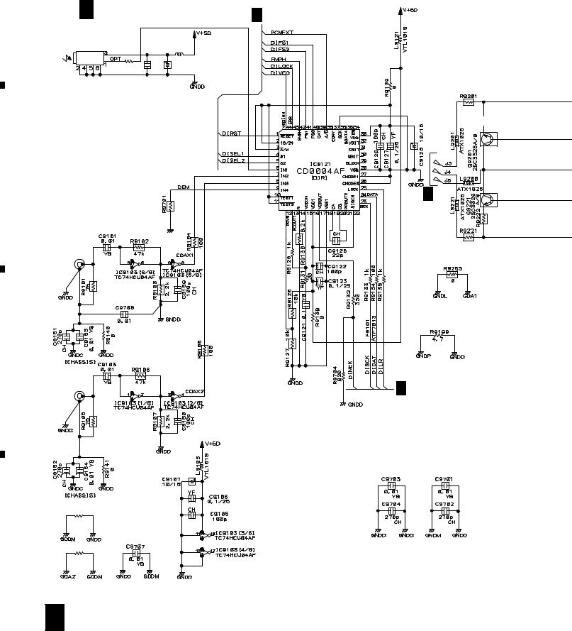
3.6 DOLBY DIGITAL ASSY (1/3)
A
H 1/3 |
DOLBY DIGITAL ASSY |
H 2/3 |
||
|
(AWX7042) |
|||
TORX176 |
|
|
VTL1019 |
|
JA9104 |
|
|
|
|
|
|
L9108 |
|
|
|
|
|
|
|
|
R9111 |
YF |
|
|
|
100 |
|
|
|
|
|
C9110 |
C9111 |
|
|
|
0.1 |
47/6.3 |
|
6.2k

 3.9k
3.9k
B
|
H 3/3 |
|
0 |
|
3.9k |
JA9000 |
6.2k |
(2/2) |
|
AKB7095 |
|
C
JA9000 |
|
|
|
(1/2) |
H |
2/3 |
|
AKB7095 |
|||
|
|
R9039
0
D |
R9038 |
|
|
|
0 |
18 H 1/3
|
1 |
|
2 |
|
3 |
|
4 |
|
|
|
|
|
|
||||
|
|
|
|
|
|
5 |
|
6 |
|
7 |
|
8 |
|
|
|
|
|
|
VSX-D607S
A
B
H 2/3
H 2/3
C
D
C 2/3 CN212
H 1/3 19
|
5 |
|
6 |
|
7 |
|
8 |
|
|
|
|
|
|
||||
|
|
|
|
|
|
1 |
|
2 |
|
3 |
|
4 |
|
|
|
|
|
|
VSX-D607S
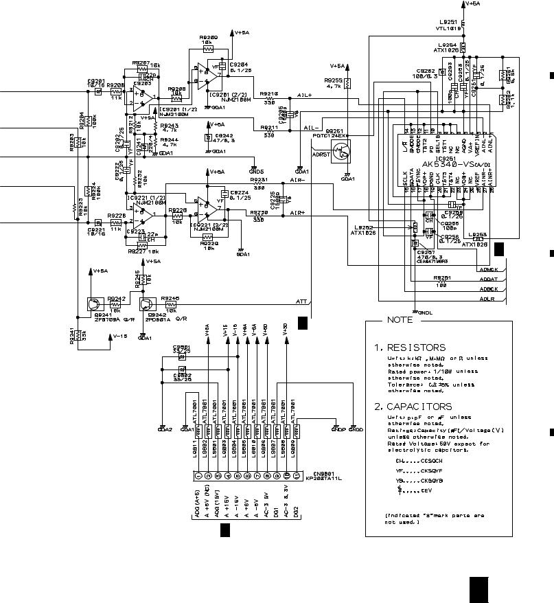
3.7 DOLBY DIGITAL ASSY (2/3)
A
H |
2/3 |
DOLBY DIGITAL ASSY |
(AWX7042) |
H 1/3
H 3/3
B
C
D
20 H 2/3
|
1 |
|
2 |
|
3 |
|
4 |
|
|
|
|
|
|
||||
|
|
|
|
|
|
5 |
|
6 |
|
7 |
|
8 |
|
|
|
|
|
|
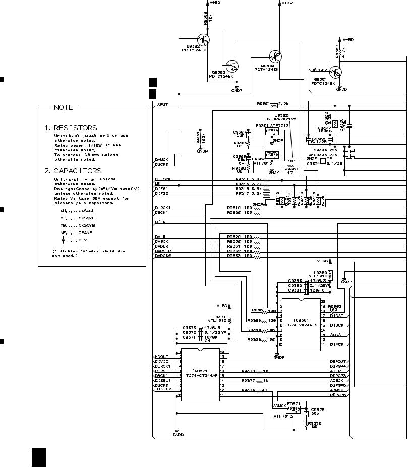
VSX-D607S
A
H 1/3
H 3/3
B
C
R9702
0
D
A J23
H 2/3 21
|
5 |
|
6 |
|
7 |
|
8 |
|
|
|
|
|
|
||||
|
|
|
|
|
 Loading...