


DVD/CD Receiver
XV-HTD640
Speaker System
S-HTD540
S-HTD630
Digital Wireless Speaker System
XW-HTD640
XW-HTD630
HTD-645DV HTD-641DV
|
|
|
|
|
|
|
|
|
|
|
|
|
|
|
|
|
|
|
|
|
|
|
|
|
|
|
|
|
|
|
|
|
|
|
|
|
|
|
|
|
|
|
|
|
|
|
|
|
|
|
|
|
|
|
|
|
|
|
|
|
|
|
|
|
|
|
|
|
|
|
|
|
|
|
|
|
|
|
|
|
|
|
|
|
|
|
|
|
|
|
|
|
|
|
|
|
|
|
|
|
|
|
|
|
|
|
|
|
|
|
|
|
|
|
|
|
|
|
|
|
|
|
|
|
|
|
|
|
|
|
|
|
|
|
|
|
|
|
|
|
|
|
|
|
|
|
|
|
|
|
|
|
|
|
|
|
|
|
|
|
|
|
|
|
|
|
|
|
|
|
|
|
|
|
|
|
|
|
|
|
|
|
|
|
|
|
|
|
|
|
|
|
|
|
|
|
|
|
|
|
|
|
|
|
|
|
|
|
|
|
|
|
|
|
|
|
|
|
|
|
|
|
|
|
|
|
|
|
|
|
|
|
|
|
|
|
|
|
|
|
|
|
|
|
|
|
|
|
|
|
|
|
|
|
|
|
|
|
|
|
|
|
|
|
|
|
|
|
|
|
|
|
|
|
|
|
|
|
|
|
|
|
|
|
|
|
|
|
|
|
|
|
|
|
|
|
|
|
|
|
|
|
|
|
|
|
|
|
|
|
|
|
|
|
|
|
|
|
|
|
|
|
|
|
|
|
|
|
|
|
|
|
|
|
|
|
|
|
|
|
|
|
|
|
|
|
|
|
|
|
|
|
|
|
|
|
|
|
|
|
|
|
|
|
|
|
|
|
|
|
|
|
|
|
|
|
|
|
|
|
|
|
|
|
|
|
|
|
|
|
|
|
|
|
|
|
|
|
|
|
|
|
|
|
|
|
|
|
|
|
|
|
|
|
|
|
|
|
|
|
|
|
|
|
|
|
|
|
|
|
|
|
|
|
|
|
|
|
|
|
|
|
|
|
|
|
|
|
|
|
|
|
|
|
|
|
|
|
|
|
|
|
|
|
|
|
|
|
|
|
|
|
|
|
|
|
|
|
|
|
|
|
|
|
|
|
|
|
|
|
|
|
|
|
|
|
|
|
|
|
|
|
|
|
|
|
|
|
|
|
|
|
|
|
|
|
|
|
|
|
|
|
|
|
|
|
|
|
|
|
|
|
|
|
|
|
|
|
|
|
|
|
|
|
XV-HTD640/S-HTD540/XW-HTD640 |
|
|
|
XV-HTD640/S-HTD630/XW-HTD630 |
||||||||||||||||||||||||||
Register your product at:
www.pioneerelectronics.com
• Protect your new investment
The details of your purchase will be on file for reference in the event of an insurance claim such as loss or theft.
•Receive free tips, updates and service bulletins on your new product
•Improve product development
Your input helps us continue to design products that meet your needs.
• Receive a free Pioneer newsletter
Registered customers can opt in to receive a monthly newsletter.
Operating Instructions
CAUTION
The lightning flash with arrowhead, within an equilateral triangle, is intended to alert the user to the presence of uninsulated "dangerous voltage" within the product's enclosure that may be of sufficient magnitude to constitute a risk of electric shock to persons.
RISK OF ELECTRIC SHOCK
DO NOT OPEN
CAUTION:
TO PREVENT THE RISK OF ELECTRIC SHOCK, DO NOT REMOVE COVER (OR BACK). NO USER-SERVICEABLE PARTS INSIDE. REFER SERVICING TO QUALIFIED SERVICE PERSONNEL.
The exclamation point within an equilateral triangle is intended to alert the user to the presence of important operating and maintenance (servicing) instructions in the literature accompanying the appliance.
D1-4-2-3_En
IMPORTANT NOTICE – THE SERIAL NUMBER FOR THIS EQUIPMENT IS LOCATED IN THE REAR.
PLEASE WRITE THIS SERIAL NUMBER ON YOUR ENCLOSED WARRANTY CARD AND KEEP IN A SECURE AREA. THIS IS FOR YOUR SECURITY.
[Excluding XW-HTD630/640]
NOTE: This equipment has been tested and found to comply with the limits for a Class B digital device, pursuant to Part 15 of the FCC Rules. These limits are designed to provide reasonable protection against harmful interference in a residential installation. This equipment generates, uses, and can radiate radio frequency energy and, if not installed and used in accordance with the instructions, may cause harmful interference to radio communications. However, there is no guarantee that interference will not occur in a particular installation. If this equipment does cause harmful interference to radio or television reception, which can be determined by turning the equipment off and on, the user is encouraged to try to correct the interference by one or more of the following measures:
–Reorient or relocate the receiving antenna.
–Increase the separation between the equipment and receiver.
–Connect the equipment into an outlet on a circuit different from that to which the receiver is connected.
– Consult the dealer or an experienced radio/TV technician for help. |
D8-10-1-2_En |
[For Canadian model only] [Pour le modèle Canadien]
CAUTION – PREVENT ELECTRIC SHOCK DO NOT USE THIS (POLARIZED) PLUG WITH AN EXTENSION CORD. RECEPTACLE OR OTHER OUTLET UNLESS THE BLADES CAN BE FULLY INSERTED TO PREVENT BLADE EXPOSURE.
ATTENTION – POUR PREVENIR LES CHOCS ELECTRIQUES NE PAS UTILISER CETTE FICHE POLARISEE AVEC UN PROLONGATEUR UNE PRISE DE COURANT OU UNE AUTRE SORTIE DE COURANT, SAUF SI LES LAMES PEUVENT ETRE INSEREES A FOND SANS EN LAISSER AUCUNE PARTIE A DECOUVVERT.
Energy-saving design
This system is designed to use 0.5W of electricity when power is switched to standby.
For U.S. and Australia Model
WARNING – TO PREVENT FIRE OR SHOCK
C67-7-3_En
HAZARD, DO NOT EXPOSE THIS APPLIANCE TO RAIN OR MOISTURE.
D1-4-2-1_En

IMPORTANT SAFETY INSTRUCTIONS
READ INSTRUCTIONS — All the safety and operating instructions should be read before the product is operated.
RETAIN INSTRUCTIONS — The safety and operating instructions should be retained for future reference.
HEED WARNINGS — All warnings on the product and in the operating instructions should be adhered to.
FOLLOW INSTRUCTIONS — All operating and use instructions should be followed.
CLEANING — The product should be cleaned only with a polishing cloth or a soft dry cloth. Never clean with furniture wax, benzine, insecticides or other volatile liquids since they may corrode the cabinet.
ATTACHMENTS — Do not use attachments not recommended by the product manufacturer as they may cause hazards.
WATER AND MOISTURE — Do not use this product near water — for example, near a bathtub, wash bowl, kitchen sink, or laundry tub; in a wet basement; or near a swimming pool; and the like.
ACCESSORIES — Do not place this product on an unstable cart, stand, tripod, bracket, or table. The product may fall, causing serious injury to a child or adult, and serious damage to the product. Use only with a cart, stand, tripod, bracket, or table recommended by the manufacturer, or sold with the product. Any mounting of the product should follow the manufacturer’s instructions, and should use a mounting accessory recommended by the manufacturer.
CART — A product and cart combination should be moved with care. Quick stops, excessive force, and uneven surfaces may cause the product and cart combination to overturn.
VENTILATION — Slots and openings in the cabinet are provided for ventilation and to ensure reliable operation of the product and to protect it from overheating, and these openings must not be blocked or covered. The openings should never be blocked by placing the product on a bed, sofa, rug, or other similar surface. This product should not be placed in a built-in installation such as a bookcase or rack unless proper ventilation is provided or the manufacturer’s instructions have been adhered to.
POWER SOURCES — This product should be operated only from the type of power source indicated on the marking label. If you are not sure of the type of power supply to your home, consult your product dealer or local power company.
LOCATION – The appliance should be installed in a stable location.
NONUSE PERIODS – The power cord of the appliance should be unplugged from the outlet when left un-used for a long period of time.
GROUNDING OR POLARIZATION |
OBJECT AND LIQUID ENTRY — Never push |
• If this product is equipped with a polarized |
objects of any kind into this product through |
alternating current line plug (a plug having one |
openings as they may touch dangerous voltage |
blade wider than the other), it will fit into the |
points or short-out parts that could result in a |
outlet only one way. This is a safety feature. If |
fire or electric shock. Never spill liquid of any |
you are unable to insert the plug fully into the |
kind on the product. |
outlet, try reversing the plug. If the plug should |
SERVICING — Do not attempt to service this |
still fail to fit, contact your electrician to replace |
product yourself as opening or removing covers |
your obsolete outlet. Do not defeat the safety |
may expose you to dangerous voltage or other |
purpose of the polarized plug. |
hazards. Refer all servicing to qualified service |
• If this product is equipped with a three-wire |
personnel. |
grounding type plug, a plug having a third |
DAMAGE REQUIRING SERVICE — Unplug this |
(grounding) pin, it will only fit into a grounding |
product from the wall outlet and refer servicing |
type power outlet. This is a safety feature. If you |
to qualified service personnel under the |
are unable to insert the plug into the outlet, |
following conditions: |
contact your electrician to replace your obsolete |
• When the power-supply cord or plug is |
outlet. Do not defeat the safety purpose of the |
damaged. |
grounding type plug. |
• If liquid has been spilled, or objects have fallen |
POWER-CORD PROTECTION — Power-supply |
into the product. |
cords should be routed so that they are not likely |
• If the product has been exposed to rain or water. |
to be walked on or pinched by items placed |
• If the product does not operate normally by |
upon or against them, paying particular |
following the operating instructions. Adjust only |
attention to cords at plugs, convenience |
those controls that are covered by the operating |
receptacles, and the point where they exit from |
instructions as an improper adjustment of other |
the product. |
controls may result in damage and will often |
OUTDOOR ANTENNA GROUNDING — If an |
require extensive work by a qualified technician |
outside antenna or cable system is connected to |
to restore the product to its normal operation. |
the product, be sure the antenna or cable |
• If the product has been dropped or damaged in |
system is grounded so as to provide some |
any way. |
protection against voltage surges and built-up |
• When the product exhibits a distinct change in |
static charges. Article 810 of the National |
performance — this indicates a need for service. |
Electrical Code, ANSI/NFPA 70, provides |
REPLACEMENT PARTS — When replacement parts |
information with regard to proper grounding of |
are required, be sure the service technician has |
the mast and supporting structure, grounding of |
used replacement parts specified by the |
the lead-in wire to an antenna discharge unit, |
manufacturer or have the same characteristics |
size of grounding conductors, location of |
as the original part. Unauthorized substitutions |
antenna-discharge unit, connection to |
may result in fire, electric shock, or other |
grounding electrodes, and requirements for the |
hazards. |
grounding electrode. See Figure A. |
SAFETY CHECK — Upon completion of any service |
LIGHTNING — For added protection for this |
or repairs to this product, ask the service |
product during a lightning storm, or when it is |
technician to perform safety checks to |
left unattended and unused for long periods of |
determine that the product is in proper |
time, unplug it from the wall outlet and |
operating condition. |
disconnect the antenna or cable system. This |
WALL OR CEILING MOUNTING — The product |
will prevent damage to the product due to |
should not be mounted to a wall or ceiling. |
lightning and power-line surges. |
HEAT — The product should be situated away from |
POWER LINES — An outside antenna system |
heat sources such as radiators, heat registers, |
should not be located in the vicinity of overhead |
stoves, or other products (including amplifiers) |
power lines or other electric light or power |
that produce heat. |
circuits, or where it can fall into such power |
|
lines or circuits. When installing an outside |
|
antenna system, extreme care should be taken |
|
to keep from touching such power lines or |
|
circuits as contact with them might be fatal. |
|
OVERLOADING — Do not overload wall outlets, |
|
extension cords, or integral convenience |
|
receptacles as this can result in a risk of fire or |
ANTENNA |
electric shock. |
|
|
LEAD IN |
|
WIRE |
|
GROUND |
|
CLAMP |
|
ANTENNA |
|
DISCHARGE UNIT |
|
(NEC SECTION 810-20) |
ELECTRIC |
|
SERVICE |
GROUNDING CONDUCTORS |
EQUIPMENT |
(NEC SECTION 810-21) |
|
GROUND CLAMPS |
Fig. A |
POWER SERVICE GROUNDING |
ELECTRODE SYSTEM |
|
|
(NEC ART 250, PART H) |
|
NEC — NATIONAL ELECTRICAL CODE |
|
D1-4-2-2_En |
[Excluding XW-HTD630/640] [For Canadian model only] [Pour le modèle Canadien]
This Class B digital apparatus complies with Canadian ICES-003.
Cet appareil numérique de la Classe B est conforme à la norme NMB-003 du Canada.
D8-10-1-3_EF
Information to User
Alteration or modifications carried out without appropriate authorization may invalidate the user’s right to operate
the equipment. |
D8-10-2_En |
CAUTION : USE OF CONTROLS OR ADJUSTMENTS OR PERFORMANCE OF PROCEDURES OTHER THAN THOSE SPECIFIED HEREIN MAY RESULT IN HAZARDOUS RADIATION EXPOSURE.
CAUTION : THE USE OF OPTICAL INSTRUMENTS WITH THIS PRODUCT WILL INCREASE EYE HAZARD. D6-8-2-1_En
This product is for general household purposes. Any failure due to use for other than household purposes (such as long-term use for business purposes in a restaurant or use in a car or ship) and which requires repair will be charged for even during the warranty period.
This product incorporates copyright protection technology that is protected by method claims of certain U.S. patents and other intellectual property rights owned by Macrovision Corporation and other rights owners. Use of this copyright protection technology must be authorized by Macrovision Corporation, and is intended for home and other limited viewing uses only unless otherwise authorized by Macrovision Corporation. Reverse engineering or disassembly is prohibited.
WARNING: Handling the cord on this product or cords associated with accessories sold with the product will expose you to lead, a chemical known to the State of California and other governmental entities to cause cancer and birth defects or other reproductive harm.
Wash hands after handling |
D36-P4_En |
[For XW-HTD630 and XW-HTD640 only]
[For U.S. model]
Changes or modifications not expressly approved by the manufacturer (party responsible) for Compliance could not void the user’s authority to operate the equipment.
[For Canadian model]
Operation is subject to the following two conditions: (1) this device may not cause interference, and (2) this device must accept any interference, including interference that may cause undesired operation of the device.
[Pour le modèle Canadien]
L’utilisation de l’appareil est soumise aux deux conditions suivantes: (1) il ne provoque pas de brouillage, et (2) il peut supporter tous les brouillages, y compris ceux qui sont en mesure de provoquer une anomalie de fonc-tionnement de l’appareil.
[For Canadian model]
To prevent radio interference to the licensed service, this device is intended to be operated indoors and away from windows to provide maximum shielding. Equipment (or its transmit antenna) that is installed outdoors is subject to licensing.
[Pour le modèle Canadien]
Pour éviter le brouillage radioélectrique des émetteurs ayant une licence, cet appareil doit être utilisé à l’intérieur des habitations et loin des fenêtres de manière à assurer la protec-tion maximale. Un équipement (ou son antenne d’émission) lorsqu’il est installé à l’extérieur ne peut être utilisé qu’après obten-tion d’une licence.

Thank you for buying this Pioneer product.
Please read through these operating instructions so that you will know how to operate your model properly. After you have finished reading the instructions, put them in a safe place for future reference.
Contents
01 Before you start
Features . . . . . . . . . . . . . . . . . . . . . . . . . . . . 8 What’s in the box . . . . . . . . . . . . . . . . . . . . . 8
Putting the batteries in the remote
control . . . . . . . . . . . . . . . . . . . . . . . . . . . . . 9
Using the remote control . . . . . . . . . . . . . . 9 Disc / content format playback
compatibility . . . . . . . . . . . . . . . . . . . . . . . . 9
CD-R/RW compatibility . . . . . . . . . . . . . . 10 DVD-R/RW compatibility . . . . . . . . . . . . . 10 PC-created disc compatibility . . . . . . . . . 10 Compressed audio compatibility . . . . . . . 10 JPEG file compatibility . . . . . . . . . . . . . . . 10
02 Connecting up
Connecting the speakers and wireless speaker system . . . . . . . . . . . . . . . . . . . . . 11 Placing the speakers . . . . . . . . . . . . . . . . . 13
Placing the wireless speaker system . . . . . 14 Wall-mounting the center and surround speaker system . . . . . . . . . . . . . . . . . . . . 15
Connecting to your TV . . . . . . . . . . . . . . . . 16 Connecting using the S-video output . . . . 16 Connecting using the component video output . . . . . . . . . . . . . . . . . . . . . . . . . . . 17
Listening to TV audio through this
system . . . . . . . . . . . . . . . . . . . . . . . . . . . 18
Using this unit with a Pioneer plasma
display . . . . . . . . . . . . . . . . . . . . . . . . . . . . 18
Using the SR+ mode with a Pioneer
plasma display. . . . . . . . . . . . . . . . . . . . . 19
Connecting the supplied antennas. . . . . . . 20 Assembling the loop antenna . . . . . . . . . 20
AM loop antenna . . . . . . . . . . . . . . . . . . . 20 FM wire antenna . . . . . . . . . . . . . . . . . . . 21
Connecting the power . . . . . . . . . . . . . . . . 21
03 Controls and displays
Front panel . . . . . . . . . . . . . . . . . . . . . . . . 22 Display. . . . . . . . . . . . . . . . . . . . . . . . . . . . 23 Remote control . . . . . . . . . . . . . . . . . . . . . 25
Transmitter (HTD-645DV) . . . . . . . . . . . . . . 28 Wireless speaker (HTD-645DV) . . . . . . . . . 28
04 Getting started
Switching on and setting up . . . . . . . . . . . 30
Setting the clock . . . . . . . . . . . . . . . . . . . 31 Using the Room Setup. . . . . . . . . . . . . . . . 31
Setting up the remote to control
your TV. . . . . . . . . . . . . . . . . . . . . . . . . . . . 32
Using the on-screen displays . . . . . . . . . . . 33
Playing discs . . . . . . . . . . . . . . . . . . . . . . . 33
Basic playback controls . . . . . . . . . . . . . 34 Resume and Last Memory. . . . . . . . . . . . 35
Changing discs . . . . . . . . . . . . . . . . . . . . . 36
DVD-Video disc menus . . . . . . . . . . . . . . 37
Video CD PBC menus . . . . . . . . . . . . . . . . 38
Listening to the radio . . . . . . . . . . . . . . . . . 39 Improving poor FM reception . . . . . . . . . 39 Memorizing stations . . . . . . . . . . . . . . . . 40 Listening to station presets . . . . . . . . . . . 40 Listening to other sources . . . . . . . . . . . . . 40 Using the wireless speaker system . . . . . . 41
05 Listening to your system
About the listening modes. . . . . . . . . . . . . 43
Auto listening mode . . . . . . . . . . . . . . . . . 43
Listening in surround sound . . . . . . . . . . . 44 Dolby Pro Logic II Music settings . . . . . . 44 Using the Advanced Surround effects . . . . 45 Using Front Surround . . . . . . . . . . . . . . . . 45
Adjusting the Advanced and Front Surround effect level . . . . . . . . . . . . . . . . 46
Listening in stereo . . . . . . . . . . . . . . . . . . . 46
Listening with headphones . . . . . . . . . . . . 46
5
En

Enhancing dialogue. . . . . . . . . . . . . . . . . . 47
Listening with a virtual surround back |
|
speaker . . . . . . . . . . . . . . . . . . . . . . . . . . . |
47 |
Using Quiet and Midnight listening |
|
modes . . . . . . . . . . . . . . . . . . . . . . . . . . . . |
47 |
Adjusting the bass and treble . . . . . . . . . . |
48 |
Boosting the bass level . . . . . . . . . . . . . . . |
48 |
06 Playing discs
Playing only CDs, SACDs and MP3 discs
(CD mode) . . . . . . . . . . . . . . . . . . . . . . . . . 49 Scanning discs . . . . . . . . . . . . . . . . . . . . . 49
Playing in slow motion. . . . . . . . . . . . . . . . 49 Frame advance/frame reverse . . . . . . . . . . 50 Using the Disc Navigator to browse the contents of a disc . . . . . . . . . . . . . . . . . . . 50
Looping a section of a disc . . . . . . . . . . . . 51
Using repeat play. . . . . . . . . . . . . . . . . . . . 52 Using random play . . . . . . . . . . . . . . . . . . 52
Creating and editing a DVD program
list . . . . . . . . . . . . . . . . . . . . . . . . . . . . . . . 53
Creating and editing a non-DVD program
list . . . . . . . . . . . . . . . . . . . . . . . . . . . . . . . 54
Other functions available from the
program menu . . . . . . . . . . . . . . . . . . . . 56 Searching a disc . . . . . . . . . . . . . . . . . . . . 56 Switching subtitles . . . . . . . . . . . . . . . . . . 57
Switching DVD audio language . . . . . . . . . 57 Switching audio channels when playing
a Video CD. . . . . . . . . . . . . . . . . . . . . . . . . 57 Zooming the screen. . . . . . . . . . . . . . . . . . 58
Switching camera angles . . . . . . . . . . . . . 58 Displaying disc information . . . . . . . . . . . . 58
07 Viewing JPEG discs
Playing a JPEG slideshow . . . . . . . . . . . . . 60 Using the JPEG Disc Navigator and Photo Browser . . . . . . . . . . . . . . . . . . . . . . . . . . . 60 Zooming the screen. . . . . . . . . . . . . . . . . . 61
08 Using the timer
Setting the wake-up timer . . . . . . . . . . . . . 62 Turning the wake-up timer on/off. . . . . . . 63 Setting the sleep timer. . . . . . . . . . . . . . . . 63
6
09 Surround sound and other settings
Using the System Setup menu . . . . . . . . . .64 Surround and sound setup options. . . . . .64 SR+ control options for Pioneer plasma displays. . . . . . . . . . . . . . . . . . . . . . . . . . . 65
Setting the channel levels . . . . . . . . . . . . . .66
10 Video Adjust menu
Video Adjust . . . . . . . . . . . . . . . . . . . . . . . . 68
Creating your own presets . . . . . . . . . . . .68
11 Initial Settings menu
Using the Initial Settings menu . . . . . . . . . .69 Video Output settings . . . . . . . . . . . . . . . . .69
Language settings. . . . . . . . . . . . . . . . . . . . 70 Display settings. . . . . . . . . . . . . . . . . . . . . . 70 Options . . . . . . . . . . . . . . . . . . . . . . . . . . . . 71 Parental Lock . . . . . . . . . . . . . . . . . . . . . . 72 Bonus Group. . . . . . . . . . . . . . . . . . . . . . . 73
12 Additional information
Optional system settings . . . . . . . . . . . . . . .74 System Setup menu options in standby . .74
Resetting the system. . . . . . . . . . . . . . . . . .75
Using and taking care of discs . . . . . . . . . .75 Titles, chapters and tracks . . . . . . . . . . . .75
DVD Video regions . . . . . . . . . . . . . . . . . .76 Handling discs . . . . . . . . . . . . . . . . . . . . . 76 Storing discs. . . . . . . . . . . . . . . . . . . . . . . 76 Discs to avoid . . . . . . . . . . . . . . . . . . . . . . 77
Proper installation and maintenance of
this system . . . . . . . . . . . . . . . . . . . . . . . . . 77
Hints on installation . . . . . . . . . . . . . . . . .77 Cleaning the pickup lens . . . . . . . . . . . . .77 Problems with condensation . . . . . . . . . .77 Moving the system unit. . . . . . . . . . . . . . .77
Power cord caution. . . . . . . . . . . . . . . . . .78
Wireless speaker system maintenance
and precautions . . . . . . . . . . . . . . . . . . . . . 78
Cleaning the exterior. . . . . . . . . . . . . . . . .78 Moving the wireless speaker . . . . . . . . . . .78 Radio wave reflections . . . . . . . . . . . . . . .79
Radio wave caution. . . . . . . . . . . . . . . . . .79 Scope of operation . . . . . . . . . . . . . . . . . .79
For safety in operation . . . . . . . . . . . . . . .80
Static electricity . . . . . . . . . . . . . . . . . . . . 80
Connecting external antennas. . . . . . . . . . .80
En

Connecting auxiliary components . . . . . . . 81
Recording mode . . . . . . . . . . . . . . . . . . . 81 Troubleshooting . . . . . . . . . . . . . . . . . . . . . 83 General . . . . . . . . . . . . . . . . . . . . . . . . . . 83
DVD/CD/Video CD player . . . . . . . . . . . . . 84
MP3/JPEG discs . . . . . . . . . . . . . . . . . . . 85 Tuner . . . . . . . . . . . . . . . . . . . . . . . . . . . . 85
Wireless speaker system . . . . . . . . . . . . . 86
Error Messages . . . . . . . . . . . . . . . . . . . . 87
Screen sizes and disc formats . . . . . . . . . . 88
Widescreen TV users . . . . . . . . . . . . . . . . 88 Standard TV users . . . . . . . . . . . . . . . . . . 88
Selecting languages using the language
code list . . . . . . . . . . . . . . . . . . . . . . . . . . . 88 Language code list . . . . . . . . . . . . . . . . . . . 89 Country code list . . . . . . . . . . . . . . . . . . . . 89 Preset code list . . . . . . . . . . . . . . . . . . . . . 90 Glossary . . . . . . . . . . . . . . . . . . . . . . . . . . . 91 Specifications . . . . . . . . . . . . . . . . . . . . . . 92
7
En

01 Before you start
Chapter 1
Before you start
Features
• DVD-Audio and SACD compatible
Experience the super high-quality audio performance of DVD-Audio and Super Audio CD (SACD).
The on-board 24-bit/192kHz DAC means that this system is fully compatible with high sampling-rate discs, capable of delivering exceptional sound quality in terms of dynamic range, low-level resolution and high-frequency detail.
•Surround sound entertainment with Dolby Digital and DTS software
The built-in Dolby Digital and DTS decoders let you enjoy great surround sound with Dolby Digital and DTS discs.
•Pure Cinema progressive scan video
When connected to a progressive scancompatible TV or monitor using the component video outputs, you can enjoy extremely stable, flicker free images, with the same frame refresh rate as the original movie.
•Picture zoom
See Zooming the screen on page 58.
•Wireless speaker system
The wireless speaker system can be used for multichannel sound with your main setup, or as a second stereo speaker system.
•Energy saving design
This system is designed to use 0.5 W of power when in standby.
What’s in the box
Please confirm that the following accessories are in the main system box when you open it.
•Remote control
•AA/R6P dry cell batteries x2
•Video cable (yellow plugs)
•AM loop antenna
•FM wire antenna
•Power cord
•These operating instructions
•Warranty card
Please confirm that the following accessories are in the speaker box when you open it.
•Speaker cables (HTD-645DV – x6 / HTD641DV – x4)
•MP3 compatibility
See Compressed audio compatibility on page 10.
•JPEG compatibility
See JPEG file compatibility on page 10.
•Graphical on-screen displays
Setting up and using your DVD home theater system is made easy using the graphical onscreen displays.
8
•Non-skid pads for speakers (HTD-645DV – 2 sheets / HTD-641DV – 1 sheet)
Please confirm that the following accessories are included with the wireless speaker system:
•AC adapter
•RCA stereo cord
•Operating Instructions (HTD-641DV only)
•Warranty card
•Power cord (HTD-645DV only)
En
Before you start |
01 |
Putting the batteries in the remote control
• Open the battery compartment cover and insert the batteries as shown.
Use two AA/R6P batteries and follow the indications ( , ) inside the compartment. Close the cover when you’re finished.
•Remote operation may become unreliable if strong sunlight or fluorescent light is shining on the system unit’s remote sensor.
•Remote controllers for different devices can interfere with each other. Avoid using remotes for other equipment located close to this system.
•Replace the batteries when you notice a fall off in the operating range of the remote.
Incorrect use of batteries can result in hazards such as leakage and bursting. Please observe the following:
•Don’t mix new and old batteries together.
•Don’t use different kinds of battery together—although they may look similar, different batteries may have different voltages.
•Make sure that the plus and minus ends of each battery match the indications in the battery compartment.
•Remove batteries from equipment that isn’t going to be used for a month or more.
•When disposing of used batteries, please comply with governmental regulations or environmental public instruction’s rules that apply in your country or area.
H048 En
Using the remote control
Keep in mind the following when using the remote control:
•Make sure that there are no obstacles between the remote and the remote sensor on the system unit.
•The remote has a range of about 23 ft. / 7 m at an angle of less than 30º.
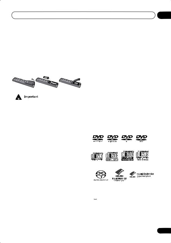
Disc / content format playback compatibility
This player is compatible with a wide range of disc types (media) and formats. Playable discs will generally feature one of the following logos on the disc and/or disc packaging. Note however that some disc types, such as recordable CD and DVD, may be in an unplayable format—see below for further compatibility information.
DVD-Audio DVD-Video DVD-R DVD-RW
Audio CD Video CD |
CD-R |
CD-RW |
Super Audio CD |
Fujicolor CD |
•KODAK Picture CD
• is a trademark of Fuji Photo Film Co. Ltd.
9
En

01 Before you start
CD-R/RW compatibility
•This system will play CD-R and CD-RW discs recorded in CD Audio or Video CD format, or as a CD-ROM containing MP3 or JPEG files. However, any other content may cause the disc not to play, or create noise/distortion in the output.
•This system cannot record CD-R or CD-RW discs.
•Unfinalized CD-R/RW discs recorded as CD Audio can be played, but the full Table of Contents (playing time, etc.) will not be displayed.
DVD-R/RW compatibility
•Compatible formats: DVD-Video, Video Recording (VR)*
*Edit points may not play exactly as edited; screen may go momentarily blank at edited points.
•Unfinalized playback: No
•MP3/JPEG file playback on DVD-R/RW: No
PC-created disc compatibility
Discs recorded using a personal computer may not be playable in this unit due to the setting of the application software used to create the disc. In these particular instances, check with the software publisher for more detailed information.
Discs recorded in packet write mode (UDF format) are not compatible with this player.
Check the DVD-R/RW or CD-R/RW software disc boxes for additional compatibility information.
Compressed audio compatibility
•Compatible formats: MPEG-1 Audio Layer 3 (MP3)
•Sampling rates: 32, 44.1 or 48kHz
•Bit-rates: Any (128Kbps or higher recommended)
•VBR (variable bit rate) MP3 playback: Yes
•VBR playback: No
•DRM (Digital Rights Management) compatible: Yes (DRM-protected audio files will not play in this player). See also DRM in the Glossary on page 91.
•File extensions: .mp3 (these must be used for the player to recognize MP3 files – do not use for other file types)
•File structure: Up to 999 files per folder
JPEG file compatibility
•Compatible formats: Baseline JPEG and EXIF 2.1* still image files up to 8 megapixels are supported (maximum resolution is 5120 x 5120 pixels).
*File format used by digital still cameras
•File extensions: .jpg (must be used for the player to recognize JPEG files – do not use for other file types)
•File structure: Up to 999 files per folder
10
En

Connecting up |
02 |
Chapter 2
Connecting up
Connecting the speakers and wireless speaker system
Connect each speaker using the color-coded speaker cable. Match them to the colored labels above the speaker terminals. Note that surround speaker are not provided with the HTD-641DV, but if you want, you can connect speakers with a nominal impedence of 6Ω–16Ω.
•Before making or changing any rear panel connections, make sure that all the components are switched off and unplugged from the power supply.
IN R |
L |
WIRELESS |
Transmitter
Surround right
(HTD-645DV only)
VIDEO |
IN |
OUT |
|
|
CONTROL |
S-VIDEO

 Y OUT
Y OUT
VIDEO
Surround left
(HTD-645DV only)
SPEAKERS |
FRONT |
|
SUB |
CENTER |
SURROUND |
|
|
R |
L |
WOOFER |
R |
L |
|
Gray
|
|
AUDIO |
OUT |
I |
Blue |
|
|
COAXIALIN |
|||
|
WIRELESS |
L |
|
||
|
|
|
|
||
OUT |
|
LINE 2 |
R |
|
|
|
|
|
|
|
|
R |
L |
|
LINE 1 |
|
|
XV-HTD640
Subwoofer
Front right |
Front left |
Center
Green
Red |
Purple |
White |
11
En
02 Connecting up
•These speaker terminals can be under
HAZARDOUS VOLTAGE. When you connect or disconnect the speaker cables, to prevent the risk of electric shock, do not touch uninsulated parts before disconnecting the power cord.
•Do not connect any of the supplied speakers to any other amplifier. This may result in malfunction or fire. This system is designed for best performance when connected to the supplied speakers. We do not, therefore, recommend connecting and using other speakers with this system.
1Twist and pull off the protective shields on each wire.
2Connect to the speaker terminals on the rear of the unit.
Match the colored wire with the color-coded label (above the tabs), then insert the colored wire into the red (+) tab and the other wire with the black (–) tab.
•Remove the supplied non-skid pads from the paper, and stick four onto the base of each satellite speaker (HTD-645DV only – refer to the setup guide for more on this). Actual speakers supplied may differ from those shown.
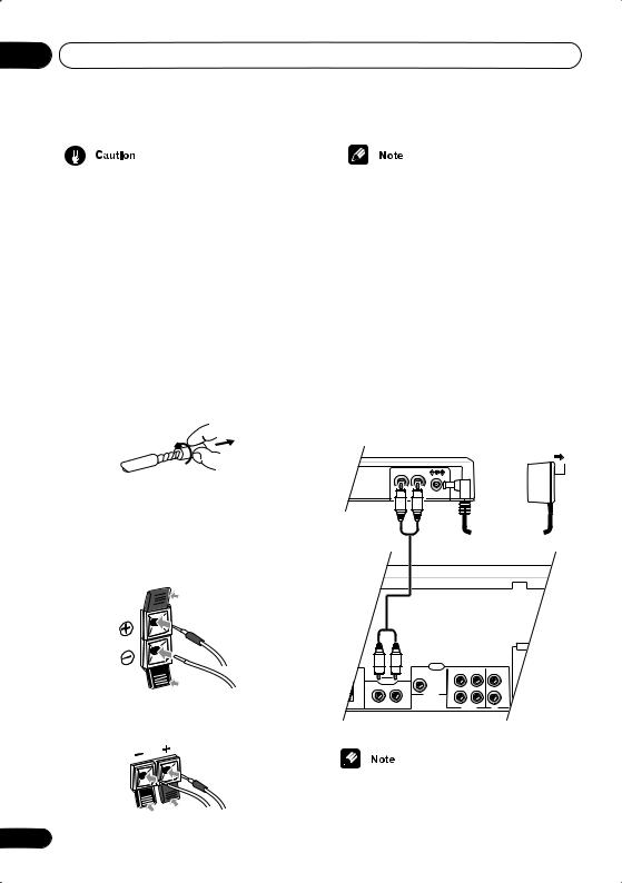
4Connect the WIRELESS (IN) jack on the transmitter to the WIRELESS (OUT) jack on the rear panel of the receiver, using the supplied RCA stereo cord.
The wireless speaker system can be used for multichannel sound with your main setup, or as a second stereo speaker system.
5Connect the supplied AC adapter to the DC IN inlet on the rear panel of the unit, then plug into a power outlet.
Transmitter
AC adaptor
IN R |
L |
To power outlet
3 Connect to the speaker terminals on the rear of the speakers in the same way.
ANTENNA
UND
L |
|
|
|
|
|
AM LOOP |
|
|
AUDIO |
|
|
|
ANTENNA |
|
|
OUT |
IN |
IN |
|
|
|
|
COAXIALIN |
|
|||
|
|
L |
|
L |
|
|
WIRELESS |
|
|
|
FM |
||
OUT |
|
|
|
|
|
|
|
LINE 2 |
|
|
|
UNBAL |
|
|
|
R |
|
R |
75 |
|
|
|
|
|
|||
R |
L |
|
LINE 1 |
|
TV |
|
|
|
|
|
|
XV-HTD640
• Do not use any AC adapter but the one provided with this system.
12
En
Connecting up |
02 |
6 When you’re finished connect the power cord to a household power outlet.
•HTD-645DV only – Before doing this, plug the supplied power cord into the wireless speaker AC IN inlet (see below).
Power outlet |
Placing the speakers
Note that the HTD-641DV does not include surround speakers. If not connected, simply set up your speakers using the Standard surround 5-spot setup shown below, disregarding the surround speakers in the diagram.
Depending on the size and characteristics of your room, you can choose to place your speakers in one of two ways using this system. Note that the following setups are possible when you are using the the wireless speaker as a second stereo system (see Using the wireless speaker system on page 41 for more on this).
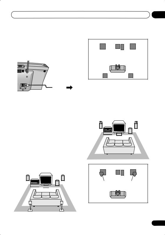
•Standard surround 5-spot setup – This is a standard multichannel surround sound speaker setup for optimal 5.1 channel home theatre sound.
Front left |
System |
Sub- |
Front right |
|
unit |
woofer |
|


 Center
Surround |
Surround |
left |
right |
Front left |
Center |
Front right |
|
Subwoofer |
|
Listening position |
|
|
Surround |
|
Surround |
left |
|
right |
•Front surround 3-spot setup – This setup is ideal when rear surround speaker placement isn’t possible or you want to avoid running long speaker cables in your listening area. Use this setup together with the Front Surround modes to take advantage of wall and ceiling reflections for a very realistic surround effect.
|
Surround |
Surround |
|
|
left |
right |
|
Front |
System |
Sub- |
Front |
unit |
woofer |
||
left |
|
|
right |
|
|
Center |
|
|
Center |
Front |
Front |
left |
right |
|
Subwoofer |
Surround |
Surround |
left |
right |
Listening position
13
En
02 Connecting up
The above illustrations are for the HTD-645DV only. If you connected surround speakers to the HTD-641DV, place them on either side of the front speakers as shown below.
|
|
|
|
|
Center |
|
|
||||||
|
|
|
|
|
|
|
|
|
|
|
|
|
|
|
|
|
|
|
|
|
|
|
|
|
|
|
|
|
|
|
|
|
|
|
|
|
|
|
|
|
|
Surround |
Front |
|
|
|
|
Surround |
|||||||
|
Subwoofer Front |
||||||||||||
|
left |
left |
|
|
|
|
right |
right |
|||||
(not supplied) |
|
|
|
|
|
|
|
|
|
(not supplied) |
|||
Listening position
See About the listening modes on page 43 for more on using the different listening modes with each speaker setup.
Where you put your speakers in the room has a big effect on the quality of the sound. The following guidelines should help you to get the best sound from your system.
•The subwoofer can be placed on the floor. Ideally, the other speakers should be at about ear-level when you’re listening to them. Putting the speakers on the floor (except the subwoofer), or mounting them very high on a wall is not recommended.
•For the best stereo effect, place the front speakers 6–9 ft. / 2–3 m apart, at equal distance from the TV.
•Install the center speaker above or below the TV so that the sound of the center channel is localized at the TV screen.
•When using a 5-spot setup, install the surround speakers slightly above ear level, if possible.
•Make sure that all speakers are securely installed (if you choose to install the center speaker on top of the TV, be sure to secure it by suitable means). This not only
14
improves sound quality, but also reduces the risk of damage or injury resulting from speakers being knocked over or falling in the event of external shocks such as earthquakes.
•The front, and center and surround speakers supplied with this system are magnetically shielded. However, placing them extremely close to a television may result in color distortion on the screen. If this happens, move the speakers a little further away and switch off the television for 15–30 minutes.
•The subwoofer is not magnetically shielded and so should not be placed near a TV or monitor.
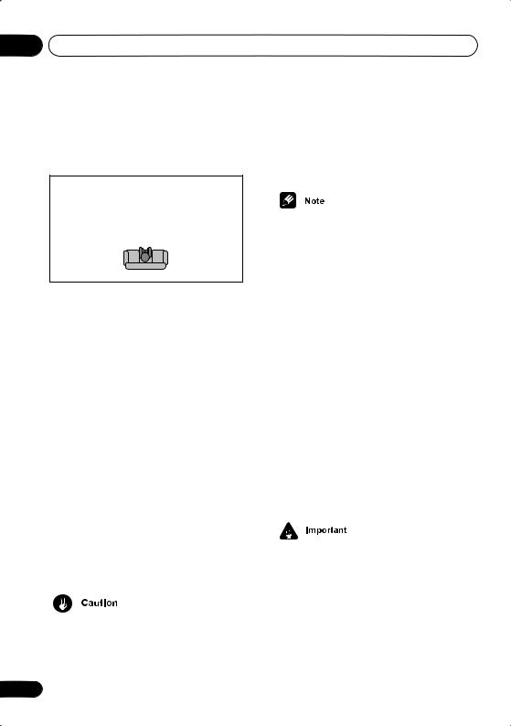
Placing the wireless speaker system
You can choose to use the wireless speaker system for multichannel sound with your main setup, or as a second stereo speaker system.
The Standard surround (5-spot) setup described in Placing the speakers above will achieve the best surround sound when using the wireless speaker system for multichannel sound (the 3-spot setup is not recommended).
•After setting up the wireless speaker for multichannel sound, see Setting the channel levels on page 66 to lower the surround speaker levels.
Note that the following illustration shows a speaker setup including surround speakers, which are not included with the HTD-641DV model. See Connecting the speakers and wireless speaker system on page 11 for more on connecting surround speakers.
En

Connecting up |
02 |
If not connected, simply set up your speakers using the Standard surround setup as shown below, disregarding the surround speakers in the diagram. Using the wireless speaker, you can still achieve exceptional surround sound from your system.
|
Transmitter/ |
|
|
Front left |
XV-HTD640 |
Sub- |
Front right |
|
|||
|
|
woofer |
|
|
|
Center |
|
Surround |
|
|
Surround |
left |
|
|
right |
Wireless speaker |
to AC outlet |
||
For best surround sound, make sure to place the wireless speaker directly behind the center of the listening position and no higher than ear level. Also, make sure you don't move the wireless speaker too far behind the listening position or you will lose much of the surround sound effect. For more placement options, see
Using the wireless speaker system on page 41.
Wall-mounting the center and surround speaker system
Surround speakers are not supplied with the HTD-641DV. Illustration shows the HTD-645DV.
Before mounting
•Remember that the speaker system is heavy and that its weight could cause the wood screws to work loose, or the wall material to fail to support it, resulting in the speaker falling. Make sure that the wall you intend to mount the speakers on is strong enough to support them. Do not mount on plywood or soft surface walls.
•Mounting screws are not supplied. Use screws that are suitable for the wall material and that will support the weight of the speaker.
5 mm
10 mm
5 mm
Wood screw
Protrusion: 5-7mm
•For a greater surround sound effect from the wireless speaker, see Setting the channel levels on page 66 to increase the surround channel levels.
•As well as setting the wireless mode on the speakers, you must also set the mode on the main unit. See Using the wireless speaker system on page 41 for more on this.
•If you are unsure of the qualities and strength of the walls, consult a professional for advice.
•Pioneer is not responsible for any accidents or damage that result from improper installation.
15
En
02 Connecting up
Connecting to your TV
This system has three different kinds of video output that you can use to connect up your TV. Check the available inputs on your TV to see which you can use.
•Do not connect a VCR between this system and your TV as DVD playback will be affected.
•Use the supplied video cable to connect the VIDEO OUT jack to a video input on your TV.
VIDEO |
INPUT |
TV |
|
VIDEO |
IN |
|
|
OUT |
|
|
PR |
|
|
|
|
|
CONTROL |
|
COMPONENT |
|
|
|
VIDEO OUT |
|
S-VIDEO |
|
PB |
Y |
OUT |
|
|
|
VIDEO |
|
SPEAKERS |
FRONT |
SUB |
CENTER |
R |
L |
WOOFER |
•Placing the system unit too close to your TV may cause interference, especially if you’re using an indoor antenna. If you notice interference, move the system unit away from the TV.
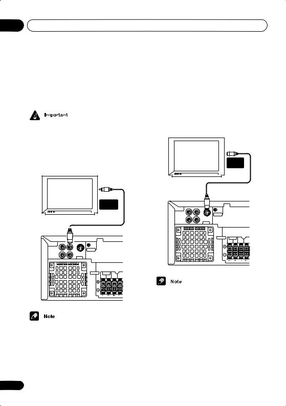
Connecting using the S-video output
If your TV has an S-video input, you can use this instead of the standard video output for a better quality picture.
• Use an S-video cable (not supplied) to connect the S-VIDEO OUT to an S-video input on your TV.
Line up the small triangle below the jack with the same mark on the plug before plugging in.
|
|
S-VIDEO |
|
|
INPUT |
TV |
|
|
|
VIDEO |
IN |
PR |
OUT |
|
|
CONTROL |
|
COMPONENT |
|
|
VIDEO OUT |
|
S-VIDEO |
PB |
Y |
OUT |
|
VIDEO |
|
SPEAKERS |
FRONT |
SUB |
CENTER |
R |
L |
WOOFER |
•The S-video output is switchable between S1 and S2 formats for compatibility with all TVs. See Video Output settings on page 69 for more on this.
16
En
Connecting up |
02 |
Connecting using the component video output
If your TV has component video inputs, you can use these instead of the standard video output to connect this system to your TV. This should give you the best quality picture from the three types of video output available.
• Use a component video cable (not supplied) to connect the COMPONENT VIDEO OUT to a set of component inputs on your TV.
COMPONENT
INPUT
TV
|
VIDEO |
IN |
|
|
OUT |
|
|
PR |
|
|
|
|
|
CONTROL |
|
COMPONENT |
|
|
|
VIDEO OUT |
|
S-VIDEO |
|
PB |
Y |
OUT |
|
|
|
VIDEO |
|
SPEAKERS |
FRONT |
SUB |
R |
L |
WOOFER |
•The component video output is switchable between interlaced and progressive formats. See Video Output settings on page 69 and Watching progressive scan video from the component video outputs below for more on this.
Watching progressive scan video from the component video outputs
Compared to interlace video, progressive scan video effectively doubles the scanning rate of the picture, resulting in a very stable, flickerfree image. Progressive scan video is available only from the component video output. There are a few things to keep in mind when switching the Component Out (page 69) setting to Progressive:
•When set to Progressive, there is no video output from the VIDEO OUT (composite) and S (S-video) jacks.
•If you want to display video on more than one monitor simultaneously, make sure the player is set to Interlace.
•If you connect a TV that is not compatible with a progressive scan signal and switch the setting to Progressive, you will not be able to see any picture at all. In this case, press STANDBY/ON to put the system in standby, then press and hold the front
panel (stop) button for about 8 seconds until the display shows Mem.Clr.?. Press the front panel or button so that the display shows Interlace?. Press the front panel button to set to interlace and switch the system back on.
Compatibility of this player with progressive-scan and high-definition TVs
This player is compatible with progressive video Macro Vision System Copy Guard.
Consumers should note that not all highdefinition television sets are fully compatible with this product and may cause artifacts to be displayed in the picture. In case of 525 progressive scan picture problems, it is recommended that the user switch the connection to the ‘standard definition’ output (Interlace).
17
En
02 Connecting up
If there are questions regarding our TV set compatibility with this model, please contact our customer service center.
This system is compatible with the following Pioneer displays and monitors:
Plasma display
PDP-505HD, PDP-5030HD, PDP-4330HD, PDP5040HD, PDP-4340HD, PRO-10000HD, PRO800HD, PRO-1000HDI, PRO-800HDI, PRO1110HD, PRO-910HD, PDP-4300, PDP-5031
Projection monitor receiver
SD-533HD5, SD-643HD5, PRO-710HD, PRO610HD, PRO-510HD, PRO-720HD, PRO-620HD, PRO-520HD, PRO-730HD, PRO-630HD, PRO530HD, PRO-730HDI, PRO-530HDI
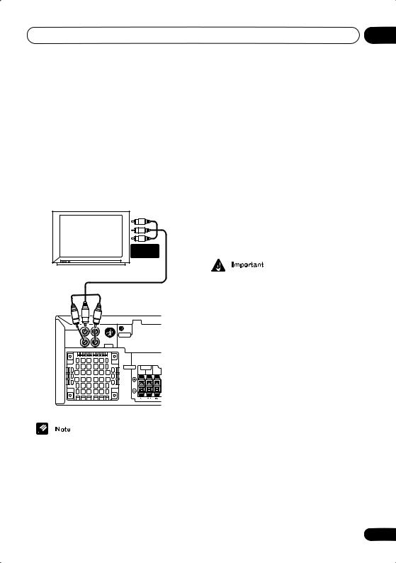
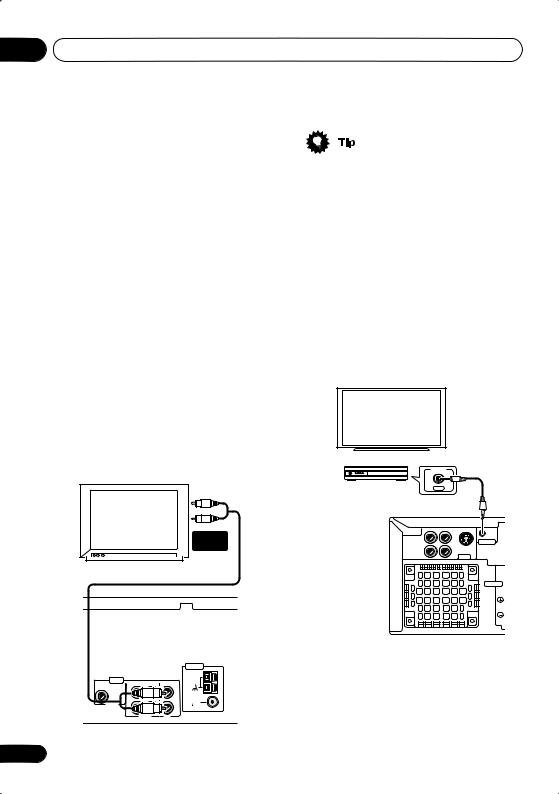
Listening to TV audio through this system
You can connect the audio output of your TV to this system so that broadcast TV sound is played through this system.
• Connect a stereo audio cable (not supplied) from the audio outputs of your TV to the TV IN jacks on this system.
AUDIO |
OUTPUT |
TV |
|
|
|
|
ANTENNA |
AUDIO |
|
|
|
AM LOOP |
OUT |
IN |
IN |
ANTENNA |
|
COAXIALIN |
|
|||
L |
|
L |
|
|
|
|
FM |
||
|
|
|
|
|
LINE 2 |
|
|
|
UNBAL |
R |
|
R |
75 |
|
|
|
|
||
|
LINE 1 |
|
TV |
|
18
•If you find that the TV audio is distorting when played through this system, you can set the input attenuator to reduce the input signal level. See Optional system settings on page 74 to do this.
Using this unit with a Pioneer plasma display
If you have a Pioneer plasma display (models PRO-1110HD, PRO-910HD, PDP-5040HD, PDP-4340HD), you can use an SR+ cable (see note below) to connect it to this unit and take advantage of various convenient features, such as automatic video input switching of the plasma display when the input is changed.
Pioneer plasma display
|
CONTROL |
Media receiver |
OUT |
|
VIDEO |
IN |
PR |
OUT |
|
COMPONENT |
|
CONTROL |
VIDEO OUT |
|
S-VIDEO |
PB |
Y |
OUT |
|
VIDEO |
|
SPEAKERS
En

Connecting up |
02 |
• Use a 3-ringed miniplug SR+ cable to connect the CONTROL IN jack of this unit through a media receiver to the CONTROL OUT jack of your plasma display.
Before you can use the extra SR+ features, you need to make a few settings in the unit. See
SR+ control options for Pioneer plasma displays on page 65 for detailed instructions.
Using the SR+ mode with a Pioneer plasma display
When connected using an SR+ cable, a number of features (such as automatic video input switching and volume muting on the plasma display) become available to make using this unit with your Pioneer plasma display even easier.
See also SR+ control options for Pioneer plasma displays on page 65 for information on setting up the unit.
1Make sure that the plasma display and this unit are switched on and that they are connected with an SR+ cable.
See Using this unit with a Pioneer plasma display above for more on connecting these components.
2To switch SR+ mode on/off, press SR+ (SHIFT + 7).
The front panel display shows the new setting;
SR+ ON or SR+ OFF.
•If SR+ Error shows in the display, it means there is a communication problem between the unit and the plasma display. Check all connections and retry.
•The 3-ringed SR+ cable from Pioneer is commercially available under the part number ADE7095. Contact the Pioneer Customer Support division for more information on obtaining an SR+ cable.
•You won’t be able to use the remote sensor of this unit with the CONTROL IN jack of this unit connected to the CONTROL OUT jack of your plasma display. You can use the remote sensor of the plasma display (even in standby) as long as the power isn’t switched off.
•The automatic volume muting feature is enabled separately; see SR+ control options for Pioneer plasma displays on page 65. (You can also use the System Setup menu to switch the SR+ mode of this unit.)
•If you disconnect the SR+ cable or switch the plasma display off while SR+ is on, the setting automatically reverts to SR+ OFF.
This displays an error if you switch the input of the unit with the plasma display switched off. Likewise, if this unit is switched off, the link with the plasma display will be terminated.
19
En
02 Connecting up
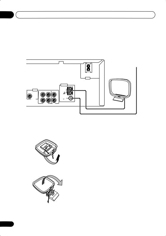
Connecting the supplied antennas
The supplied antennas provide a simple way to listen to AM and FM radio. If you find that reception quality is poor, an outdoor antenna should give you better sound quality—see Connecting external antennas on page 80 for more on how to do this.
FM wire (PAL) antenna
AM loop antenna
AC IN
|
|
|
|
ANTENNA |
AUDIO |
|
|
|
AM LOOP |
OUT |
IN |
IN |
ANTENNA |
|
COAXIALIN |
|
|||
L |
|
L |
|
|
|
|
FM |
||
|
|
|
|
|
LINE 2 |
|
|
|
UNBAL |
R |
|
R |
75 |
|
|
|
|
||
|
LINE 1 |
|
TV |
|
Assembling the loop antenna
1 Bend the stand in the direction indicated.
2 Clip the loop onto the stand.
AM loop antenna
1Pull off the protective shields of both AM antenna wires.
2Press the antenna terminal tabs to open and insert one wire into each terminal.
3Release the tabs to secure the AM antenna wires.
4Place the AM antenna on a flat surface and point in the direction giving the best reception.
Avoid placing near computers, television sets or other electrical appliances and do not let it come into contact with metal objects.
20
En
Connecting up
•It’s also possible to fix the AM antenna to a wall using two screws (see illustration below). Before fixing, make sure that the reception is satisfactory.
FM wire antenna
• Connect the FM wire antenna to the FM UNBAL 75Ω terminal in the same way as the AM loop antenna.
For best results, extend the FM antenna fully and fix to a wall or door frame. Don’t drape loosely or leave coiled up.
• The signal ground ( ) is designed to reduce noise that occurs when an antenna is connected. It is not an electrical safety ground.
02
Connecting the power
Before connecting the power and switching on for the first time make sure that everything is connected properly.
AC IN
ANTENNA
AM LOOP
ANTENNA
FM UNBAL 75
Power outlet
1Plug one end of the supplied power cord into the AC INLET.
2Plug the other end into a household power outlet.
•See Connecting auxiliary components on page 81 for details of other connections you can make with this system.
21
En
03 Controls and displays
Chapter 3
Controls and displays
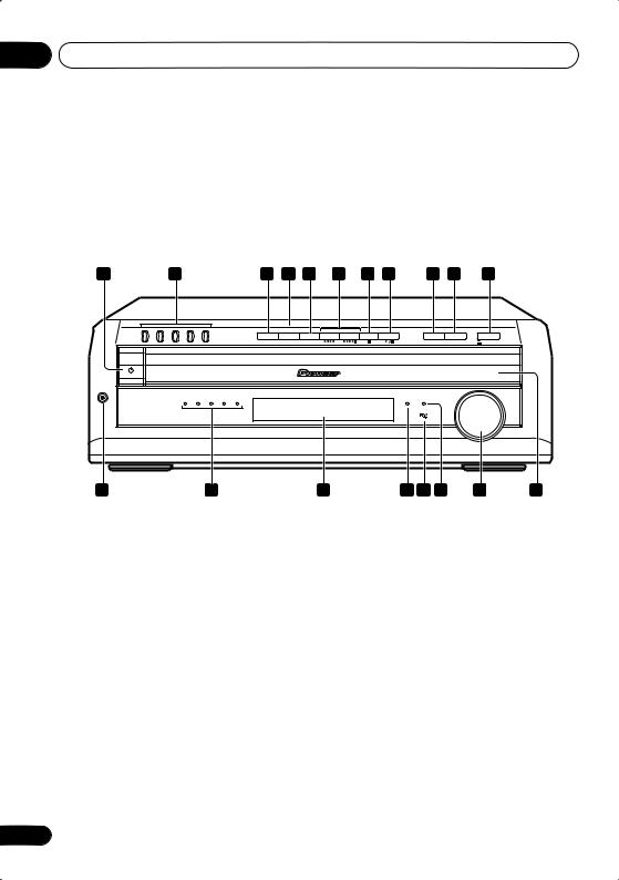
Front panel
1 |
|
|
2 |
|
3 |
4 |
5 |
6 |
7 |
8 |
9 |
10 |
11 |
DIRECT PLAY |
|
|
|
|
|
FM/AM/ST. |
|
|
|
|
|
|
|
1 |
2 |
3 |
4 |
5 |
DVD/CD |
TUNER |
TV/L1/L2 |
|
|
|
DISC SKIP |
EXCHANGE |
OPEN/CLOSE |
STANDBY/ON
PHONES
DISC |
|
|
|
|
|
VOLUME |
1 |
2 |
3 |
4 |
5 |
CD MODE TIMER |
|
|
|
|
|
|
DOWN |
UP |
|
19 |
18 |
17 |
16 15 14 |
13 |
12 |
1 |
STANDBY/ON (page 30) |
|
• When in listening to the tuner, use to tune |
|||
Press to switch the system on or into standby. |
|
to stations or select presets. |
|
|||
2 |
DIRECT PLAY buttons (page 34) |
|
7 |
|
|
|
Press to start playback of any disc in the |
|
Press to stop playback. |
|
|
||
player. |
|
|
8 |
|
|
|
|
|
|
|
|
|
|
3 DVD/CD (page 33)
Press to switch to the DVD/CD function. Also starts/pauses/resumes playback of the currently loaded disc.
4 TUNER FM/AM/ST. (page 39)
Press to switch to the tuner function, then between bands and station presets.
5 TV/L1/L2 (page 40)
Press to switch between the external sources,
TV, LINE 1 (L1) and LINE 2 (L2).
6 and
Press to skip tracks/chapters; press and hold to scan backwards/forwards.
Press to start or resume playback. During playback, press to pause; press again to restart playback.
9DISC SKIP (page 34, 36)
•During playback, press to start playing the next disc in the player.
•If the disc tray is open while no disc is playing, the tray rotates one disc space.
•If the disc tray was opened using the EXCHANGE button, then pressing DISC SKIP rotates the disc tray two disc spaces.
22
En
Controls and displays |
03 |
10 EXCHANGE (page 36)
Press during playback to open the disc tray without stopping playback. Press again to close the disc tray.
11 OPEN/CLOSE
Press to open/close the disc tray.
12Disc tray
13VOLUME control
Use to adjust the volume.
14Timer indicator (page 62) Lights when the timer is set.
15


This mark indicates compatibility with DVDRW discs recorded on a DVD recorder in Video Recording (VR) mode.
16 CD MODE indicator (page 49)
Lights when the CD Mode is on. In this mode, the system only plays audio CDs and MP3 discs.
17 Display
See Display on page 23 for detailed information.
18 DISC indicators
Shows which disc spaces are currently occupied.
19 PHONES jack
Headphone jack.
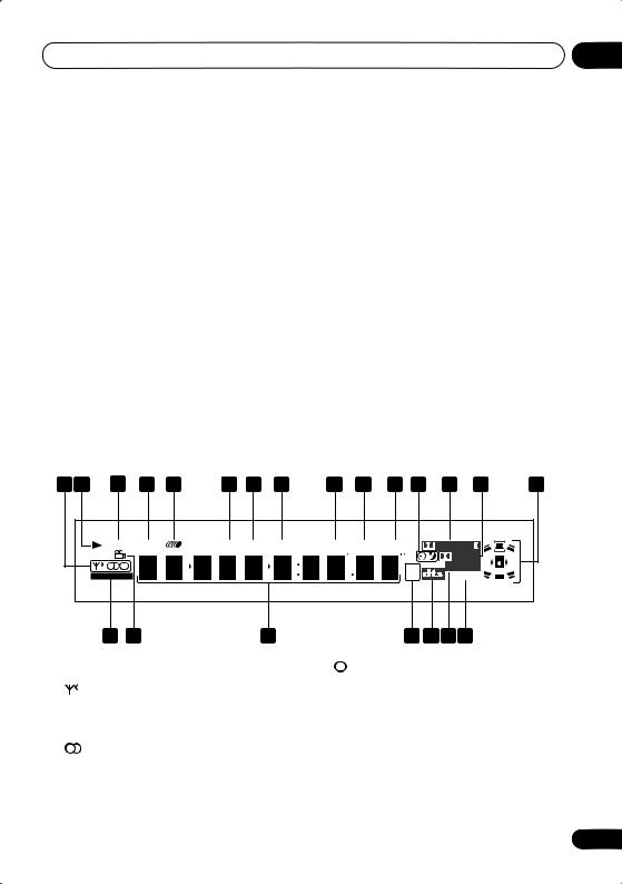
Display |
|
|
|
|
|
|
|
|
|
|
|
|
|
|
||
1 |
2 |
3 |
|
4 |
5 |
|
6 |
7 |
8 |
9 |
10 |
11 |
12 |
13 |
14 |
15 |
|
|
MIDNIGHT |
QUIET |
|
MANNER |
PGM |
RPT-1 |
RDM |
V.PART |
ATT |
REC MODE |
PRO LOGIC |
|
|
||
|
|
|
|
|
|
|
|
|
|
|
|
|
|
DIGITAL |
|
|
|
|
|
|
|
|
|
|
|
|
|
|
|
kHz |
ADV.SURR. |
|
|
|
|
WIRELESS |
|
|
|
|
|
|
|
|
|
|
MHz |
Neo:6PRGSVE |
|
|
|
|
22 |
21 |
|
|
|
|
20 |
|
|
|
19 18 17 16 |
|
|
||
1Tuner indicators (page 39)
Lights when a broadcast is being received.
Lights when a stereo FM broadcast is being received in auto stereo mode.
Lights when FM mono reception is selected.
2
Lights when a disc is playing.
3 MIDNIGHT (page 47)
Lights when the Midnight mode is selected.
4 QUIET (page 47)
Lights when the Quiet mode is selected.
23
En
03 Controls and displays
5
Lights to indicate random or repeat play of all discs loaded.
6 PGM (page 53)
Lights when a program list has been programmed.
7 RPT and RPT-1 (page 52)
RPT lights during repeat play. RPT-1 lights during repeat one-track play.
8 RDM (page 52)
Lights during random play.
9 V.PART
Lights when playing a video part of a DVD disc.
10 ATT (page 74)
Lights when the input attenuator is active for the currently selected analog input.
11REC MODE (page 81) Lights when Rec Mode is on.
12Timer indicators (page 62)
Lights when the timer is set
Lights when the sleep timer is active
132 PRO LOGIC II (page 44)
Lights during Dolby Pro Logic II decoding.
14 2 DIGITAL (page 44)
Lights during playback of a Dolby Digital source.
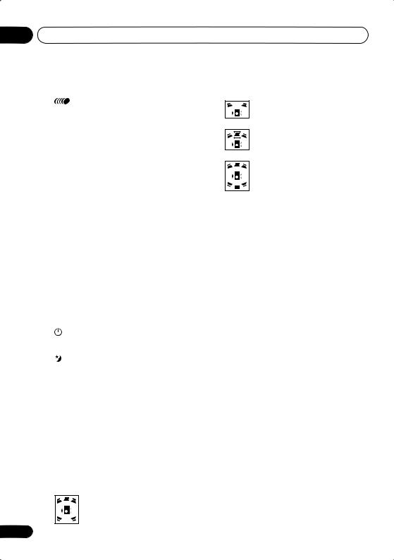
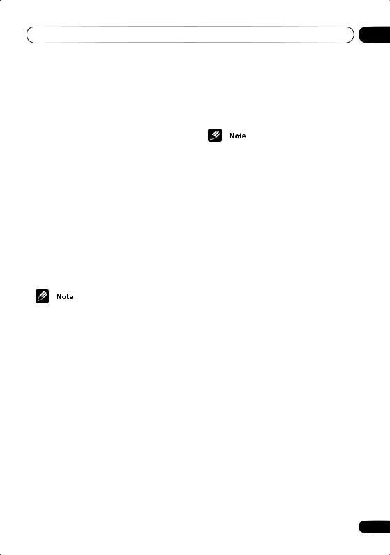
15 Speaker indicators
These show which speakers are being used to output the current source (they are not placement diagrams). The illustrations below show some example displays.
5.1 channel surround sound
24
Stereo (2.1 channel) sound
3.1 channel sound with Dialogue enhancement on the center channel
5.1 channel surround sound with Virtual Surround Back mode active
(When headphones are connected, none of the speaker indicators are lit.)
16 PRGSVE (page 69)
Lights when progressive scan video output is selected.
17 ADV.SURR. (page 45)
Lights when one of the Advanced or Front Surround listening modes is selected.
18  (page 44)
Lights during playback of a DTS source.
19 kHz / MHz
Indicates the unit of the frequency shown in the character display (kHz for AM, MHz for FM)
20Character display
21 (page 58)
Lights during multi-angle scenes on a DVD disc.
22 WIRELESS
Lights when the W.Surr. mode is selected (see Using the wireless speaker system on page 41).
En
Controls and displays
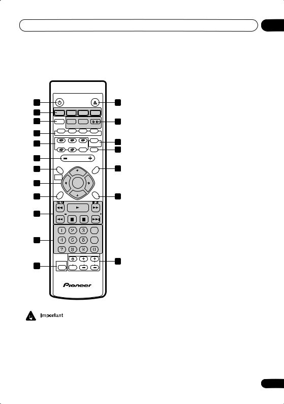
Remote control
|
STANDBY/ON |
OPEN/CLOSE |
|
|||
1 |
|
|
|
|
2 |
|
3 |
|
FM/AM |
|
L1/L2 |
|
|
DVD/CD |
TUNER |
TV |
LINE |
|
||
4 |
|
DIALOGUE |
VIR.SR |
BASSMODE |
5 |
|
SOUND |
SURROUND |
ADVANCED |
FRONT |
|||
|
|
|||||
|
MODE |
|
|
SURROUND |
|
|
6 |
AUDIO |
SUBTITLE ANGLE |
ZOOM |
|
||
|
|
|
|
WIRELESS |
|
|
8 |
DISC 1 |
DISC 2 |
DISC 3 |
ROOM |
7 |
|
|
|
CDMODE |
SETUP |
9 |
||
|
DISC 4 |
DISC 5 |
DISCSKIP |
MUTE |
||
|
|
|||||
10 |
|
VOLUME |
|
|
||
11 |
SYSTEM SETUP |
|
TOP MENU |
12 |
||
|
TUNE + |
|
||||
|
|
|
|
|||
|
HOME |
|
|
DVD MENU |
|
|
|
MENU |
|
|
|
|
|
13 |
ST – |
ST + |
|
|||
|
ENTER |
|
|
|||
|
|
|
|
|||
|
QUIET/ |
|
|
|
|
|
|
MIDNIGHT |
|
|
RETURN |
|
|
14 |
|
TUNE – |
|
15 |
||
|
|
|
|
|||
16 |
FOLDER |
|
|
FOLDER |
|
|
|
|
|
|
|||
|
PROGRAM REPEAT RANDOM |
|
|
|||
|
|
|
|
CLEAR |
|
|
17 |
TEST TONE CH LEVEL |
TIMER |
|
|
||
|
|
|
ENTER |
|
||
|
SR + |
DISPLAY |
DIMMER |
|
|
|
|
|
TV CONTROL |
|
|||
19 |
SHIFT |
INPUT |
CHANNEL |
VOLUME |
18 |
|
|
|
|
|
|
||
|
5.1ch DVD |
SURROUND |
SYSTEM |
|
|
|
•Functions printed in green on the remote control are accessed using the SHIFT button. Press the function button you want while holding down SHIFT.
1 STANDBY/ON (page 30)
Press to switch the system on or into standby.
03
2 OPEN/CLOSE
Press to open/close the disc tray.
3 Function select buttons
Press to select the source you want to listen to (DVD/CD, TUNER, TV, LINE).
4 SOUND MODE
Press to access the sound menu, from which you can adjust the DSP effect level, bass and treble, etc. (pages 44–48) Also switches the recording mode on/off (page 81).
5 Surround sound and enhancement buttons
SURROUND (page 44)
Use to select a Surround mode.
DIALOGUE (SHIFT + SURROUND)
(page 47)
Use to select a Dialogue mode.
ADVANCED (page 45)
Use to select an Advanced Surround mode.
VIR. SB (SHIFT + ADVANCED) (page 47) Press to switch the Virtual Surround Back speaker effect on/off.
FRONT SURROUND (page 45)
Use to select a Front Surround listening mode.
BASS MODE (SHIFT + FRONT
SURROUND) (page 48)
Use to select a Bass Mode.
6DVD buttons
AUDIO (page 57)
Press to select an audio channel or language.
SUBTITLE (page 57)
Press to display/change the subtitle display.
25
En

03 Controls and displays
ANGLE (page 58)
Press to change camera angle during DVD multi-angle scene playback.
ZOOM (page 58)
Press to change the screen zoom level.
7ROOM SETUP (page 31) Press to start Room Setup.
WIRELESS (SHIFT+ROOM SETUP)
Press to switch between surround modes with the wireless speaker system (see
Using the wireless speaker system on page 41).
8Disc selection buttons
DISC select buttons (page 33) Use to select discs in the player.
DISC SKIP / CD MODE
•During playback, press to start playing the next disc in the player.
•If the disc tray is open while no disc is playing, the tray rotates one disc space.
•If the disc tray was opened using the EXCHANGE button (front panel only), then pressing DISC SKIP rotates the disc tray two disc spaces. (page 34, 36)
•Use with SHIFT for CD MODE: Use to switch CD Mode on/off. (page 49)
9MUTE
Press to mute all sound from the speakers and headphones (press again to cancel).
10 VOLUME
Use to adjust the volume.
11HOME MENU / SYSTEM SETUP
•Press to display (or exit) the on-screen menu for Initial Settings, Play Mode functions, etc.
•Use with SHIFT for SYSTEM SETUP: Use to make various system and surround sound settings. (page 64)
26
12DVD MENU / TOP MENU
•Press to display a DVD-Video disc menu, or the Disc Navigator if a VR mode DVD-RW, CD, Video CD, MP3 or JPEG disc is loaded.
•Use with SHIFT for TOP MENU: Use to display the top menu of a DVD disc in the play position (this may be the same as pressing DVD MENU).
13Cursor buttons, ENTER and tuning buttons
Cursor buttons
Use the cursor buttons (/ / /) to navigate on-screen displays and menus.
ENTER
Press to select an option or execute a command.
TUNE +/–
Use to tune the radio.
ST +/–
Use to select station presets when listening to the radio.
14 QUIET/MIDNIGHT (page 47)
Use to select Quiet and Midnight listening modes.
15 RETURN
Press to return to a previous menu screen.
16 Playback controls
Press to start or resume playback.
and
Use for reverse slow motion playback, frame reverse and reverse scanning.
and
Use for forward slow motion playback, frame advance and forward scanning.
En

Controls and displays |
03 |
/ FOLDER –
Press to jump to the beginning of the current chapter/track, then to previous chapters/tracks.
Press SHIFT + to jump to the beginning of the previous folder
/ FOLDER +
Press to jump to the next chapter/track (or folder by pressing SHIFT + ).
Press to pause playback; press again to restart.
Press to stop playback.
17 Number buttons and SHIFT functions
Use the number buttons for selecting chapters/tracks from a disc directly; use with the SHIFT button to access the functions printed in green.
PROGRAM (SHIFT + 1) (page 53) Use to program/play a program list.
REPEAT (SHIFT + 2) (page 52)
Use to select a repeat play mode.
RANDOM (SHIFT + 3) (page 52) Use to select a random play mode.
TEST TONE (SHIFT + 4) (page 66)
Use to output the test tone (for speaker setup).
CH LEVEL (SHIFT + 5) (page 66)
Use to adjust the speaker level.
TIMER (SHIFT + 6) (page 62)
Press to display the clock and to access the timer menu.
SR+ (SHIFT + 7) (page 19)
Press to switch SR+ on or off.
DISPLAY (SHIFT + 8) (page 58)
Press to display/change disc information shown on-screen.
DIMMER (SHIFT + 9)
Press to switch between normal and dimmed front panel display.
CLEAR
Press to clear an entry.
ENTER
Press to select menu options, etc. (works exactly the same as the ENTER button in 13 above).
18 TV CONTROL buttons
These buttons are dedicated to control the TV assigned to the TV button.
Use to turn on/off the power of the TV.
INPUT
Use to select the TV function.
TV CHANNEL +/–
Use to select channels.
TV VOLUME +/–
Use to adjust the volume on your TV.
19 SHIFT
Use to access the functions/commands printed in green on the remote (press the button for the function you want while holding down SHIFT).
27
En
03 Controls and displays
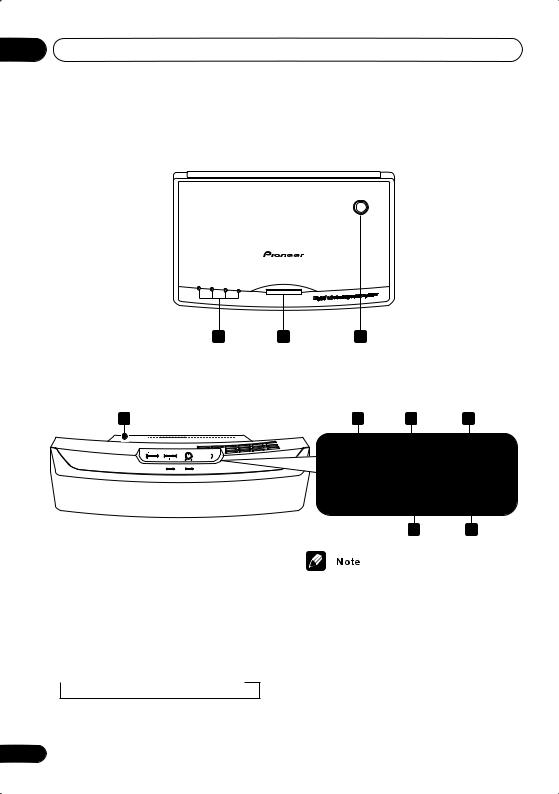
Transmitter (HTD-645DV)
With the HTD-641DV model, please refer to the XW-HTD630 wireless speaker manual.
1 |
|
|
CHANNEL |
2 |
3 |
4 |
|
|
|
1 2 3
Wireless speaker (HTD-645DV)
With the HTD-641DV model, please refer to the XW-HTD630 wireless speaker manual.
4
1 CHANNEL indicators
Light to indicate the selected channel.
2 CHANNEL
In case of poor reception due to interference from other electrical devices, you can improve reception by selecting another channel. Each time you press the button, the channel changes sequentially:
 CH 1
CH 1  CH 2
CH 2  CH 3
CH 3  CH 4
CH 4
5 |
|
6 |
|
7 |
POWER |
WIRELESS |
STEREO MODE |
||
|
VOLUME |
|||
MODE |
|
|||
OFF ON |
|
|
||
|
W.SURROUND |
W.STEREO |
MIN |
MAX |
|
POWER |
|
TUNED |
|
8 9
•Poor reception may cause the audio to be interrupted or to disappear completely. This is not a malfunction. Try changing the location or orientation of the transmitter and/or the wireless speaker to improve reception.
•The wireless speaker can be used at distances of up to 10m from the transmitter. This range may change depending on the environment.
28
En
Controls and displays |
03 |
3 Transmitter antenna
Transmits signals to the wireless speaker.
4Wireless speaker antenna
Receives signals from the transmitter.
5POWER
Press to switch the unit on or off.
6 WIRELESS MODE switch
Slide to select either W.SURROUND or
W.STEREO mode. See Using the wireless speaker system on page 41 for more on these modes.
•W.SURROUND — Sounds going to the surround left and right channels are heard through the wireless speakers.
•W.STEREO — Any source playing through the main system is heard in stereo through the wireless speakers (multichannel sources will be downmixed to stereo).
•The system should be in standby when switching between modes (see Using the wireless speaker system on page 41).
•If the mode of the wireless speaker system and the mode of the DVD receiver do not match, loud noise may be output from the wireless speaker system.
•The STEREO MODE VOLUME control can be used to adjust the volume when W.STEREO is selected.
7 STEREO MODE VOLUME
Turn to adjust the speaker volume when the
WIRELESS MODE is set to W.STEREO.
When set to W.SURROUND, the volume control does not operate. The volume changes automatically.
8 POWER indicator
Lights when the wireless speaker is switched on.
9 TUNED indicator
Lights when the signal from the transmitter is properly received.
•For more on using the wireless speaker system Using the wireless speaker system on page 41.
29
En
 Loading...