


STEREO CD CASSETTE DECK RECEIVER
AMPLI-TUNER/LECTEUR CD/DOUBLE PLATINE A CASSETTE
XR-A370
XR-A670
SPEAKER SYSTEM
ENCEINTES ACOUSTIQUES
S-A370
S-A670
Operating Instructions
Mode d'emploi
'
WARNING: TO PREVENT FIRE OR SHOCK HAZARD, DO NOT EXPOSE THIS APPLIANCE TO RAIN OR MOISTURE.
ATTENTION: AFIN DE PREVENIR TOUS RISQUES DE CHOC ELECTRIQUE OU DE DEBUT D’ENCENDIE, NE PAS EXPOSER CET APPAREIL A L’HUMIDITE OU A LA PLUIE.
IMPORTANT
CAUTION
The lightning flash with arrowhead symbol, within an equilateral triangle, is intended to alert the user to the presence of uninsulated "dangerous voltage" within the product's enclosure that may be of sufficient magnitude to constitute a risk of electric shock to persons.
RISK OF ELECTRIC SHOCK
DO NOT OPEN
CAUTION:
TO PREVENT THE RISK OF ELECTRIC SHOCK, DO NOT REMOVE COVER (OR BACK). NO USER-SERVICEABLE PARTS INSIDE. REFER SERVICING TO QUALIFIED SERVICE PERSONNEL.
Theexclamationpointwithinanequilateraltriangleisintended to alert the user to the presence of important operating and maintenance (servicing) instructions in the literature accompanying the appliance.
IMPORTANT SAFETY INSTRUCTIONS
READ INSTRUCTIONS — All the safety and operating instructions should be read before the product is operated.
RETAIN INSTRUCTIONS — The safety and operating instructions should be retained for future reference.
HEED WARNINGS — All warnings on the product and in the operating instructions should be adhered to.
FOLLOW INSTRUCTIONS — All operating and use instructions should be followed.
CLEANING — Unplug this product from the wall outlet before cleaning. The product should be cleaned only with a polishing cloth or a soft dry cloth. Never clean with furniture wax, benzine, insecticides or other volatile liquids since they may corrode the cabinet.
ATTACHMENTS — Do not use attachments not recommended by the product manufacturer as they may cause hazards.
WATER AND MOISTURE — Do not use this product near water — for example, near a bathtub, wash bowl, kitchen sink, or laundry tub; in a wet basement; or near a swimming pool; and the like.
ACCESSORIES — Do not place this product on an unstable cart, stand, tripod, bracket, or table. The product may fall, causing serious injury to a child or adult, and serious damage to the product. Use only with a cart, stand, tripod, bracket, or table recommended by the manufacturer, or sold with the product. Any mounting of the product should follow the manufacturer’s instructions, and should use a mounting accessory recommended by the manufacturer.
CART — A product and cart combination should be moved with care. Quick stops, excessive force, and uneven surfaces may cause the product and cart combination to overturn.
VENTILATION — Slots and openings in the cabinet are provided for ventilation and to ensure reliable operation of the product and to protect it from overheating, and these openings must not be blocked or covered. The openings should never be blocked by placing the product on a bed, sofa, rug, or other similar surface. This product should not be placed in a built-in installation such as a bookcase or rack unless proper ventilation is provided or the manufacturer’s instructions have been adhered to.
POWER SOURCES — This product should be operated only from the type of power source indicated on the marking label. If you are not sure of the type of power supply to your home, consult your product dealer or local power company.
LOCATION – The appliance should be installed in a stable location.
NONUSE PERIODS – The power cord of the appliance should be unplugged from the outlet when left un-used for a long period of time.
GROUNDING OR POLARIZATION |
OBJECT AND LIQUID ENTRY — Never push objects of |
÷ If this product is equipped with a polarized alternating |
any kind into this product through openings as they |
current line plug (a plug having one blade wider than |
may touch dangerous voltage points or short-out |
the other), it will fit into the outlet only one way. This |
parts that could result in a fire or electric shock. |
is a safety feature. If you are unable to insert the plug |
Never spill liquid of any kind on the product. |
fully into the outlet, try reversing the plug. If the plug |
SERVICING — Do not attempt to service this product |
should still fail to fit, contact your electrician to |
yourself as opening or removing covers may expose |
replace your obsolete outlet. Do not defeat the |
you to dangerous voltage or other hazards. Refer all |
safety purpose of the polarized plug. |
servicing to qualified service personnel. |
÷ If this product is equipped with a three-wire |
DAMAGE REQUIRING SERVICE —Unplug this product |
grounding type plug, a plug having a third (grounding) |
from the wall outlet and refer servicing to qualified |
pin, it will only fit into a grounding type power outlet. |
service personnel under the following conditions: |
This is a safety feature. If you are unable to insert the |
÷ When the power-supply cord or plug is damaged. |
plug into the outlet, contact your electrician to |
÷ If liquid has been spilled, or objects have fallen into |
replace your obsolete outlet. Do not defeat the |
the product. |
safety purpose of the grounding type plug. |
÷ If the product has been exposed to rain or water. |
POWER-CORD PROTECTION — Power-supply cords |
÷ If the product does not operate normally by following |
should be routed so that they are not likely to be |
the operating instructions. Adjust only those controls |
walked on or pinched by items placed upon or |
that are covered by the operating instructions as an |
against them, paying particular attention to cords at |
improper adjustment of other controls may result in |
plugs, convenience receptacles, and the point where |
damage and will often require extensive work by a |
they exit from the product. |
qualified technician to restore the product to its |
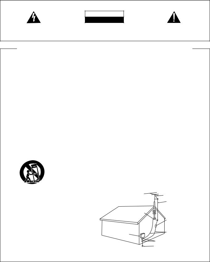
OUTDOOR ANTENNA GROUNDING — If an outside |
normal operation. |
antenna or cable system is connected to the product, |
÷ If the product has been dropped or damaged in any |
be sure the antenna or cable system is grounded so |
way. |
as to provide some protection against voltage surges |
÷ When the product exhibits a distinct change in |
and built-up static charges. Article 810 of the National |
performance — this indicates a need for service. |
Electrical Code, ANSI/NFPA 70, provides information |
REPLACEMENT PARTS — When replacement parts |
with regard to proper grounding of the mast and |
are required, be sure the service technician has used |
supporting structure, grounding of the lead-in wire |
replacement parts specified by the manufacturer or |
to an antenna discharge unit, size of grounding |
have the same characteristics as the original part. |
conductors, location of antenna-discharge unit, |
Unauthorized substitutions may result in fire, electric |
connection to grounding electrodes, and |
shock, or other hazards. |
requirementsforthegroundingelectrode.SeeFigure |
SAFETY CHECK — Upon completion of any service or |
A. |
repairs to this product, ask the service technician to |
LIGHTNING — For added protection for this product |
perform safety checks to determine that the product |
during a lightning storm, or when it is left unattended |
is in proper operating condition. |
and unused for long periods of time, unplug it from |
WALL OR CEILING MOUNTING — The product should |
the wall outlet and disconnect the antenna or cable |
not be mounted to a wall or ceiling. |
system. This will prevent damage to the product |
HEAT — The product should be situated away from heat |
due to lightning and power-line surges. |
sources such as radiators, heat registers, stoves, or |
POWER LINES — An outside antenna system should |
other products (including amplifiers) that produce |
not be located in the vicinity of overhead power lines |
heat. |
or other electric light or power circuits, or where it |
|
can fall into such power lines or circuits. When |
|
installing an outside antenna system, extreme care |
|
should be taken to keep from touching such power |
|
lines or circuits as contact with them might be fatal. |
|
OVERLOADING — Do not overload wall outlets, |
ANTENNA |
extension cords, or integral convenience receptacles |
|
as this can result in a risk of fire or electric shock. |
LEAD IN |
|
WIRE |
GROUND |
|
CLAMP |
|
|
ANTENNA |
|
DISCHARGE UNIT |
|
(NEC SECTION 810-20) |
ELECTRIC |
GROUNDING CONDUCTORS |
SERVICE |
(NEC SECTION 810-21) |
EQUIPMENT |
|
|
GROUND CLAMPS |
|
POWER SERVICE GROUNDING |
Fig. A |
ELECTRODE SYSTEM |
|
(NEC ART 250, PART H) |
NEC — NATIONAL ELECTRICAL CODE
2
En/Fr
Energy-saving design
This system is designed to use minimal electricity whenpower is switched OFF (during Standby).
Regarding the value of the Power Consumption in standby mode, refer to specifications on page 46.
IMPORTANT NOTICE
[For U.S. and Canadian models]
The serial number for this equipment is located on the rear panel.Pleasewritethisserialnumberonyourenclosedwarranty card and keep it in a secure area. This is for your security.
[For Canadian model]
CAUTION: TO PREVENT ELECTRIC SHOCK DO NOT USE THIS (POLARIZED) PLUG WITH AN EXTENSION CORD, RECEPTACLE OR OTHER OUTLET UNLESS THE BLADES CAN BE FULLY INSERTED TO PREVENT BLADE EXPOSURE.
[For Canadian model]
This Class B digital apparatus complies with Canadian ICES-003.
Conception visant à réduire la consommation électrique
Cet ensemble a été conçu de telle sorte que la consommation d’énergie électrique est aussi réduite que possible pendant les périodes de veille.
Pour connaître la valeur de la puissance consommée pendant les périodes de veille, veuillez vous reporter aux caractéristiques techniques qui figurent aux pages 47.
REMARQUE IMPORTANTE
Le numéro de série de cet appareil se trouve sur son panneau arrière.Pours’yréférerencasdebesoin,prièred’inscrirecenuméro surlacartedegarantieinclueetdelaconserverdansunendroitsûr.
ATTENTION: POUR PREVENIR LES CHOCS ELECTRIQUES NE PAS UTILISER CETTE FICHE POLARISEE AVEC UN PROLONGATEUR, UNE PRISE DE COURANT OU UNE AUTRE SORTIE DE COURANT, SAUF SI LES LAMES PEUVENT ETRE INSEREES A FOND SANS EN LAISSER AUCUNE PARTIE A DECOUVERT.
[Pour le modèle Canadien]
Cet appareil numérique de la Classe B est conforme à la norme NMB003 du Canada.
[For U. S. model]
CAUTION
÷Use of controls or adjustments or performance of procedures other than those specified herein may result in hazardous radiation exposure.
÷The use of optical instruments with this product will increase eye hazard.
Information to User
Alteration or modifications carried out without appropriate authorization may invalidate the user's right to operate the equipment.
This equipment has been tested and found to comply with the limits for a Class B digital device, pursuant to Part 15 of the FCC Rules. These limits are designed to provide reasonable protection against harmful interference in a residential installation. This equipment generates, uses, and can radiate radio frequency energy and, if not installed and used in accordance with the instructions, may cause harmful interference to radio communications. However, there is no guarantee that interference will not occur in a particular installation. If this equipment does cause harmful interference to radio or television reception, which can be determined by turning the equipment off and on, the user is encouraged to try to correct the interference by one or more of the following measures:
–Reorient or relocate the receiving antenna.
–Increase the separation between the equipment and receiver.
–Connect the equipment into an outlet on a circuit different from that to which the receiver is connected. –Consult the dealer or an experienced radio/TV technician for help.
|
|
|
|
IC |
IN |
D |
|
|
|
|
|
|
|
|
|
N |
|
|
|
|
|
|
|
||
|
|
|
O |
|
|
S |
|
|
|
|
|
|
|
T |
R |
|
|
|
U |
|
|
|
|
|
|
|
|
|
|
|
|
|
|
|
|
|
||
C |
|
|
|
|
|
R |
|
|
|
|
|
|
|
|
|
|
|
|
I |
|
|
|
|
||
E |
|
|
|
|
|
|
E |
|
|
|
|
|
L |
|
|
|
|
|
|
|
|
|
|||
E |
|
|
|
|
|
S |
|
|
|
|
||
A |
EST |
1924 |
• |
|
||||||||
• |
|
|
|
ION |
|
|
|
|
|
|
||
|
|
SS |
|
|
|
|
We |
|
|
|
||
|
|
|
|
|
|
|
|
|||||
|
|
|
|
O CIAT |
|
|
Want You |
|
||||
LISTENING
For A Lifetime
Selecting fine audio equipment such as the unit you’ve just purchased is only the start of your musical enjoyment. Now it’s time to consider how you can maximize the fun and excitement your equipment offers. This manufacturer and the Electronic Industries Association’s Consumer Electronics Group want you to get the most out of your equipment by playing it at a safe level. One that lets the sound come through loud and clear without annoying blaring or distortion-and, most importantly, without affecting your sensitive hearing.
Sound can be deceiving. Over time your hearing “comfort level” adapts to higher volumes of sound. So what sounds “normal” can actually be loud and harmful to your hearing. Guard against this by setting your equipment at a safe level BEFORE your hearing adapts.
To establish a safe level:
÷Start your volume control at a low setting.
÷Slowly increase the sound until you can hear it comfortably and clearly, and without distortion.
Once you have established a comfortable sound level:
÷ Set the dial and leave it there.
Taking a minute to do this now will help to prevent hearing damage or loss in the future. After all, we want you listening for a lifetime.
We Want You Listening For A Lifetime
Used wisely, your new sound equipment will provide a lifetime of fun and enjoyment. Since hearing damage from loud noise is often undetectable until it is too late, this manufacturer and the Electronic Industries Association’s Consumer Electronics Group recommend you avoid prolonged exposure to excessive noise. This list of sound levels is included for your protection.
Decibel
Level Example
30 Quiet library, soft whispers
40 Living room, refrigerator, bedroom away from traffic
50 Light traffic, normal conversation, quiet office
60 Air conditioner at 20 feet, sewing machine
70 Vacuum cleaner, hair dryer, noisy restaurant
80 Average city traffic, garbage disposals, alarm clock at two feet.
THE FOLLOWING NOISES CAN BE DANGEROUS UNDER CONSTANT EXPOSURE
90 Subway, motorcycle, truck traffic, lawn mower
100 Garbage truck, chain saw, pneumatic drill
120 Rock band concert in front of speakers, thunderclap
140 Gunshot blast, jet plane
180 Rocket launching pad
Information courtesy of the Deafness Research Foundation.
|
|
|
|
IC |
IN |
D |
|
|
|
|
|
|
|
|
|
|
|
N |
|
|
|
|
|
|
|
||
|
|
R |
O |
|
|
U |
|
|
|
|
|
|
|
|
T |
|
|
|
|
S |
|
|
|
|
|
|
|
C |
|
|
|
|
|
|
R |
|
|
|
|
|
|
|
|
|
|
|
|
|
I |
|
|
|
|
|
|
E |
|
|
|
|
|
|
|
E |
|
|
|
|
|
L |
|
|
|
|
|
|
|
|
|
|
|
||
E |
|
|
|
|
|
|
S |
|
|
|
|
|
|
|
|
|
|
|
|
|
|
|
We |
||||
• |
|
EST |
1924 |
|
• |
Want You |
|||||||
A |
|
||||||||||||
|
|
|
|
S O CIAT |
|
|
LISTENING |
||||||
|
|
S |
|
ION |
|
|
|
|
|
|
|||
For A Lifetime
3
Français English
En/Fr

CAUTION
This product contains a laser diode of higher class than 1. To ensure continued safety, do not remove any covers or attempt to gain access to the inside of the product.
Refer all servicing to qualified personnel.
The following caution label appears on your unit.
Location: rear of the unit
CLASS 1
LASER PRODUCT
Demo Function
The Demo mode starts automatically when the power cord is plugged into the power outlet.
Also, when the P.BASS (DEMO) button is pressed for more than 3 seconds in the STANDBY mode, the Demo mode is activated.
In the demo mode, various patterns appear on the display.
÷The Demo mode can be cancelled by pressing the STANDBY/ON button or function button.
÷When the P.BASS (DEMO) button is pressed for more than 3 seconds in the demonstrate mode, the demonstration stops and the demonstration function is cancelled. When the demonstration function is cancelled, the demonstration is not carried out even when the power cord is connected again. To resume demonstration function, press the P.BASS (DEMO) button for more than 3 seconds in the standby mode.
Thank you for buying this Pioneer product.
Please read through these operating instructions so you will know how to operate your model properly. After you have finished reading the instructions, put them away in a safe place for future reference. In some countries or regions, the shape of the power plug and power outlet may sometimes differ from that shown in the explanatory drawings. However, the method of connecting and operating the unit is the same.
POWER-CORD CAUTION
Handle the power cord by the plug. Do not pull out the plug by tugging the cord and never touch the power cord when your hands are wet as this could cause a short circuit or electric shock. Do not place the unit, a piece of furniture, etc., on the power cord, or pinch the cord. Never make a knot in the cord or tie it with other cords. The power cords should be routed such that they are not likely to be stepped on. A damaged power cord can cause a fire or give you an electrical shock. Check the power cord once in a while. When you find it damaged, ask your nearest PIONEER authorized service center or your dealer for a replacement.
CAUTIONS REGARDING HANDLING
Location
Install the unit in a well-ventilated location where it will not be exposed to high temperatures or humidity.
Do not install the unit in a location which is exposed to direct rays of the sun, or near stoves or radiators. Excessive heat can adversely affect the cabinet and internal components. Installation of the unit in a damp or dusty environment may also result in a malfunction or an accident (avoid installation near cookers, etc., where the unit may be exposed to oily smoke, steam or heat).
Ventilation
When installing this unit, make sure to leave space around the unit for ventilation to improve heat radiation (at least 30 cm at top, 15 cm at rear, and 15 cm at each side). If not enough space is provided between the unit and walls or other equipment, heat will build up inside, interfering with performance or causing malfunctions.
Precautions regarding installation
÷Placing and using the unit for long periods on heat-generating sources will affect performance. Avoid placing the unit on heatgenerating sources.
÷Install the unit as far away as possible from your TV. Installation in close proximity to such equipment may cause noise or degradation of the picture.
÷Such noise may be particularly noticeable when an indoor antenna is used. In such cases, make use of an outdoor antenna, or turn off the power to the unit.
÷Please place this unit on a level surface.
Condensation
When this unit is brought into a warm room from previously cold surroundings or when the room temperature rises sharply, condensation may form inside, and the unit may not be able to attain its full performance. To prevent this, allow the unit to stand for about an hour before switching it on, or raise the room temperature gradually.
4
En/Fr
ATTENTION
Ce produit renferme une diode à laser d'une catégorie supérieure à 1. Pour garantir une sécurité constante, ne pas retirer les couvercles ni essayer d'accéder à l'intérieur de l'appareil.
Pour toute réparation, s'adresser à un personnel qualitié.
La note suivante se trouve sulr le panneau arrière de cet appareil.
Emplacement: arrière de l'appareil.
CLASS 1
LASER PRODUCT
Fonction DEMO (démonstration)
L'appareil passe automatiquement en mode DEMO lorsque la fiche est introduite dans la prise de courant.
Lorsque vous appuyez plus de 3 secondes sur la touche P.BASS (DEMO) en mode STANDBY, le mode DEMO est également activé. En mode Demo, divers modèles apparaissent à l’écran.
÷Le mode DEMO peut être désactivé en appuyant sur la touche STANDBY/ON ou sur la touche de fonction.
÷Lorsque vous appuyez plus de 3 secondes sur la touche P.BASS (DEMO) en mode DEMO, la démonstration s'arrête et la fonction démonstration est désactivée. Lorsque la fonction démonstration est désactivée, il n'y aura pas de démonstration, même si vous branchez de nouveau le cordon d'alimentation. Pour reprendre la fonction démonstration, appuyez plus de 3 secondes sur la touche P.BASS (DEMO) en mode STANDBY.
Nous vous remercions de l'achat de cet appareil Pioneer.
Lisez ces directives pour apprendre comment utiliser cet appareil. Conservez-les ensuite afin de pouvoir vous y référer ultérieurement. Dans certains pays ou certaines régions, la fiche et la prise de courant peuvent parfois prendre une autre forme que celle qui figure dans les illustrations. La façon de raccorder et de faire fonctionner l'appareil est toutefois la même.
NOTE IMPORTANTE SUR LE CABLE D’ALIMENTATION
Tenir le câble d’alimentation par la fiche. Ne pas débrancher la prise en tirant sur le câble et ne pas toucher le câble avec les mains mouillées. Cela risque de provoquer un court-circuit ou un choc électrique. Ne pas poser l’appareil ou un meuble sur le câble. Ne pas pincer le câble. Ne pas faire de noeud avec le câble ou l’attacher à d’autres câbles. Les câbles d’alimentation doivent être posés de façon à ne pas être écrasés. Un câble abîmé peut provoquer un risque d’incendie ou un choc électrique. Vérifier le câble d’alimentation de temps en temps. Contacter le service après-vente PIONEER le plus proche ou le revendeur pour un remplacement.
AVERTISSEMENTS CONCERNANT L'EMPLOI
Emplacement
Installez l'appareil dans un endroit bien aéré, où il ne sera pas exposé à la chaleur ou à l'humidité.
N'installez pas l'appareil dans un endroit exposé aux rayons de soleil directsouàproximitédepoêlesouderadiateurs.Unechaleurexcessive peut avoir des conséquences néfastes sur le coffret et sur les composants à intérieur. L'installation de l'appareil dans des endroits humides peut également causer des dysfonctionnements ou des accidents (évitez d'installer l'appareil à proximité de cuisinières, etc., où il peut être exposé à la vapeur huileuse, à la fumée ou à la chaleur).
Précautions concernant l'installation
÷Si vous posez l'appareil ou si vous l'utilisez de façon permanente sur des sources de chaleur, ses performances en seront affectées. Evitez de poser l'appareil sur des sources qui dégagent de la chaleur.
÷Installez l'appareil aussi loin que possible de votre téléviseur. Si vous l'installez à proximité, l'image peut subir des dégradations ou peut être parasitée.
÷Ces parasites se voient surtout lorsque vous utilisez une antenne intérieure. Dans de tels cas, utilisez une antenne extérieure ou mettez l'appareil hors tension.
÷Veillez à mettre l'appareil sur une surface plane.
Ventilation
Lors de l'installation de l'appareil, veillez à laisser suffisamment d'espace autour pour permettre une bonne ventilation et l'évacuation de la chaleur (au moins 30 cm au-dessus, 15 cm à l'arrière et 15 cm de chaque côté). S'il n'y a pas suffisamment d'espace entre l'appareil et les parois ou les autres équipements qui l'entourent, la chaleur s'accumule à l'intérieur de l'appareil et affectera ses performances ou causera des dysfonctionnements.
Condensation
Lorsque cet appareil est déplacé d'un endroit où il fait froid vers une pièce chauffée ou lorsque la température ambiante monte brusquement, il peut y avoir des phénomènes de condensation à l'intérieur et l'appareil ne pourrait plus fonctionner de façon optimale. Afin d'éviter ce désagrément, attendez environ une heure avant d'allumer l'appareil ou faites monter progressivement la température ambiante.
5
Français English
En/Fr

CONTENTS |
|
CAUTIONS REGARDING HANDLING ............................................ |
4 |
CONFIRM SUPPLIED ACCESSORIES ........................................... |
7 |
LOADING BATTERIES INTO THE REMOTE CONTROL UNIT ....... |
7 |
REMOTE CONTROL OPERATIONS .............................................. |
7 |
CONNECTIONS ............................................................................. |
8 |
NAMES AND FUNCTIONS OF PARTS ........................................ |
12 |
SETTING THE CLOCK .................................................................. |
16 |
TUNING INTO STATIONS ............................................................ |
17 |
Beat cut function ..................................................................... |
17 |
To change the frequency step ................................................ |
18 |
MEMORIZING STATIONS ........................................................... |
18 |
Manual presetting ................................................................... |
18 |
Station call............................................................................... |
19 |
LISTENING TO COMPACT DISCS ............................................... |
20 |
To play a compact disc ............................................................ |
20 |
To remove a disc ..................................................................... |
20 |
To stop playback ..................................................................... |
21 |
To search for a particular track ................................................ |
21 |
VARIOUS OPERATIONS OF THE CD PLAYER ............................ |
22 |
A Selecting a different disc during play ................................. |
22 |
B To repeat playback (Repeat playback) ................................ |
22 |
C To play all discs and all tracks in random order |
|
(Random playback) ............................................................. |
23 |
TO PLAY ONLY DESIRED TRACKS ............................................. |
24 |
Programmed playback |
|
— To program tracks in desired order .................................... |
24 |
To clear all of the programmed commands ............................ |
24 |
OPERATIONS OF THE DISPLAY ................................................. |
25 |
PLAYING TAPES .......................................................................... |
26 |
Basic operation ....................................................................... |
26 |
For playing back from the beginning of a song |
|
(MUSIC SEARCH function) ..................................................... |
28 |
RECORDING ................................................................................ |
28 |
Recording on a tape ................................................................ |
28 |
Recording on a tape from CD A.S.E.S. |
|
(Auto Synchro Editing System) ............................................... |
30 |
Tape copy (COPY) ................................................................... |
32 |
CHANGING THE SOUND PRESENCE/TONE |
|
(SOUND MORPHING) ................................................................. |
33 |
Switching the sound morphing ............................................... |
33 |
Memorizing desired settings .................................................. |
35 |
CAUTIONS REGARDING COMPACT DISC HANDLING .............. |
36 |
HOW TO HANDLE CASSETTE TAPES ........................................ |
37 |
TIMER PLAYBACK/TIMER RECORDING ..................................... |
38 |
Setting the WAKE-UP timer .................................................... |
38 |
Timer recording setting ........................................................... |
40 |
To change timer settings ........................................................ |
41 |
If you make a mistake when setting the timer ....................... |
41 |
SLEEP TIMER .............................................................................. |
42 |
Sleep timer — Automatically turns off the power .................. |
42 |
MAINTENANCE ........................................................................... |
43 |
Cleaning the head section ....................................................... |
43 |
Demagnetizing the cassette deck heads ................................ |
43 |
Maintenance of external surfaces........................................... |
43 |
TROUBLESHOOTING .................................................................. |
44 |
SPECIFICATIONS ......................................................................... |
46 |
TABLE DES MATIERES |
|
AVERTISSEMENTS CONCERNANT L'EMPLOI ............................. |
5 |
VERIFIER LES ACCESSOIRES FOURNIS ...................................... |
7 |
INTRODUIRE LES PILES DANS LA TELECOMMANDE ................ |
7 |
OPERATIONS DE TELECOMMANDE ........................................... |
7 |
RACCORDEMENTS ....................................................................... |
8 |
NOMS ET FONCTIONS DES PIECES .......................................... |
13 |
REGLER L'HORLOGE .................................................................. |
16 |
RECHERCHER DES STATIONS ................................................... |
17 |
Fonction suppression de battements (Beat Cut) .................... |
17 |
Pour modifier l’incrément de fréquence ................................. |
18 |
MEMORISER DES STATIONS ..................................................... |
18 |
Préréglage manuel .................................................................. |
18 |
Appel de station ...................................................................... |
19 |
ECOUTER DES DISQUES COMPACTS ....................................... |
20 |
Lire un disque compact........................................................... |
20 |
Retirer un disque ..................................................................... |
20 |
Arrêter la lecture ..................................................................... |
21 |
Rechercher une piste particulière ........................................... |
21 |
OPERATIONS DIVERSES SUR LE LECTEUR DE CD .................. |
22 |
A Sélectionner un autre disque pendant la lecture ................ |
22 |
B Répéter la lecture (Repeat playback) .................................. |
22 |
C Lire tous les disques et toutes les pistes dans un ordre |
|
aléatoire (Random Playback) .............................................. |
23 |
LIRE SEULEMENT LES PISTES SOUHAITEES ............................ |
24 |
Lecture programmée |
|
— Programmer des pistes dans un ordre voulu ................................ |
24 |
Effarer toutes les commandes programmées ........................ |
24 |
OPERATIONS D'AFFICHAGE ...................................................... |
25 |
LECTURE DE CASSETTES ........................................................... |
26 |
Opérations de base ................................................................. |
26 |
Lire à partir du début d'une chanson |
|
(fonction MUSIC SEARCH) ........................................................ |
28 |
ENREGISTRER ............................................................................. |
28 |
Enregistrer sur une cassette ................................................... |
28 |
Enregistrer un CD sur une cassette avec la fonction A.S.E.S. |
|
(Auto Synchro Editing System) ............................................ |
30 |
Copie de cassette (COPY) ....................................................... |
32 |
CHANGER LA PRESENCE SONORE/LE TIMBRE |
|
(SOUND MORPHING) .................................................................. |
33 |
Activer la manipulation du son ................................................ |
33 |
Mémoriser les réglages préférés ............................................ |
35 |
PRECAUTIONS CONCERNANT L'USAGE DU DISQUE COMPACT .. |
36 |
COMMENT UTILISER LES CASSETTES ...................................... |
37 |
LECTURE MINUTEE/ENREGISTREMENT MINUTE .................... |
38 |
Mettre le réveil (WAKE-UP) .................................................... |
38 |
Réglage de l'enregistrement minuté ...................................... |
40 |
Changer les réglages de la minuterie ...................................... |
41 |
Si vous faites une erreur en réglant la minuterie .................... |
41 |
ARRET AUTOMATIQUE .............................................................. |
42 |
Arrêt automatique – Mettre automatiquement hors tension .. |
42 |
ENTRETIEN .................................................................................. |
43 |
Nettoyer la section de la tête .................................................. |
43 |
Démagnétiser les têtes du lecteur de cassettes .................... |
43 |
Entretien des surfaces extérieures ......................................... |
43 |
DEPANNAGE ............................................................................... |
45 |
CARACTERISTIQUES TECHNIQUES ........................................... |
47 |
6
En/Fr

CONFIRM SUPPLIED ACCESSORIES |
|
VERIFIER LES ACCESSOIRES FOURNIS |
|||
1 |
|
2 |
3 |
4 |
5 |
1 |
2 |
3 |
|
|
|
1 |
Remote control unit x 1 |
1 Télécommande x 1 |
2 |
FM antenna x 1 |
2 Antenne FM x 1 |
3 |
AM loop antenna x 1 |
3 Antenne cadre AM x 1 |
4 |
AA/R6P dry cell batteries x 2 |
4 Piles sèches AA/R6P x 2 |
5 |
Power cord x 1 |
5 Cordon d’alimentation x 1 |
LOADING BATTERIES INTO THE |
|
INTRODUIRE LES PILES DANS LA |
REMOTE CONTROL UNIT |
|
TELECOMMANDE |
1 |
2 |
3 |
Français English
1Open the battery compartment cover on the back of the remote control unit.
2Insert two AA/R6P dry cell batteries into the battery compartment in accordance with the indications (ª, ·) inside the compartment.
3 Close the cover of the battery case.
Incorrect use of batteries may cause leakage or rupture. Always be sure to follow these guidelines:
A.Always insert batteries into the battery compartment correctly matching the positive ªand negative ·polarities, as shown by the display inside the compartment.
B.Never mix new and used batteries.
C.Batteries of the same size may have different voltages, depending on brand. Do not mix different brands of batteries.
1 Ouvrez le coffret à piles à l'arrière de la télécommande.
2Introduisez des piles de taille AA/R6P dans le coffret en prenant les marques (ª, ·) à l'intérieur du coffret comme repère.
3 Remettez le couvercle du coffret à piles en place.
Une utilisation erronée des piles peut provoquer des fuites, voire une explosion.
Respectez les instructions suivantes:
A.Introduisez toujours les piles dans le bon sens en faisant correspondre les repères de polarité ª et · des piles avec ceux qui figurent à l'intérieur du coffret.
B.Ne mélangez jamais piles neuves et piles usagées.
C.Des piles de la même forme peuvent avoir une tension différente selon la marque. Ne mélangez pas des différentes marques de pile.
|
REMOTE CONTROL OPERATIONS |
|
|
OPERATIONS DE TELECOMMANDE |
|
|
|
|
|
||
|
|
|
|
|
|
|
|
|
|
|
|
|
|
|
|
|
|
The remote control unit can be used within a range of approx.
7 meters (23 feet) from the remote sensor, and within angles of up to approx. 30 degrees.
NOTE:
If the remote control sensor window is in a position where it receives strong light such as sunlight or fluorescent light, control may not be possible.
L’unité de télécommande peut être utilisée dans un rayon d’action d’environ 7 m à partir du capteur de télécommande avec des angles allant jusqu’à environ 30°.
REMARQUE:
Si le capteur reçoit une lumière forte, comme des rayons de soleil ou une lumière fluorescente, le fonctionnement de la télécommande
peut être entravé.
7
En/Fr
|
CONNECTIONS |
|
|
RACCORDEMENTS |
|
|
|
|
|
|
|
|
|
|
|||
|
|
|
|
|
|
|
|
|
|
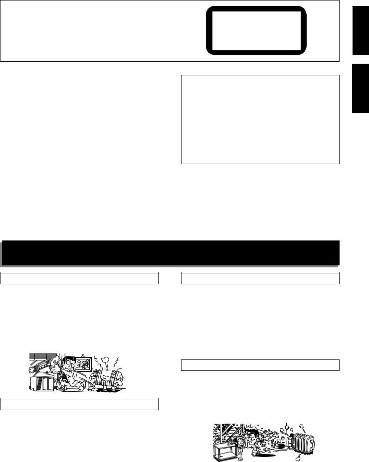
The illustration shows XR-A670. |
|
Component (DAT, MD, |
|
|
|
|
|
|
L'illustration montre la XR-A670. |
|
etc.) that has an optical |
|
|
|
|
|
|
|
|
digital input jack. |
|
|
|
|
|
|
Rear speaker system (sold separately) |
|
Composant (DAT, MD, etc.) |
VCR |
MD |
|
|
|
|
AM loop antenna |
avec prise jack pour entrée |
|
|
||||
|
Enceintes arrières (vendues séparément) |
optique numérique. |
Magnétoscope |
MD (Minidisc) |
FM antenna |
|||
|
Antenne cadre AM |
|||||||
|
|
|
|
|
|
|||
Antenne FM
XR-A370 does not have this terminal.
Le modèle XR-A370 ne possède pas cette prise.
Front speaker (R)
Enceinte avant droite
|
AM |
FM |
|
|
|
LOOP |
UNBAL |
|
|
|
ANTENNA |
75Ω |
|
|
|
|
ANTENNA |
|
Front speaker (L) |
|
|
|
|
|
R |
L |
L |
|
Enceinte avant gauche |
AUX IN |
|
AC |
|
|
|
|
R |
INLET |
|
|
|
|
|
|
R |
L |
|
|
|
REAR |
|
|
|
|
SPEAKERS |
|
|
|
|
ª |
|
|
|
|
· |
|
|
|
|
|
R |
L |
|
|
|
FRONT |
|
|
|
|
SPEAKERS |
|
|
|
|
|
XR-A370 do not have these terminals. |
To the AC wall outlet |
|
|
|
Vers la prise de courant |
||
|
|
Les modèles XR-A370 ne possèdent pas ces prises. |
|
|
7Before making or changing the connections, switch off the power button and disconnect the power cord from
the AC outlet.
÷Be sure to connect an antenna. If you don't, broadcast reception will not be possible.
÷Also refer to “ANTENNA CONNECTIONS” on page 10.
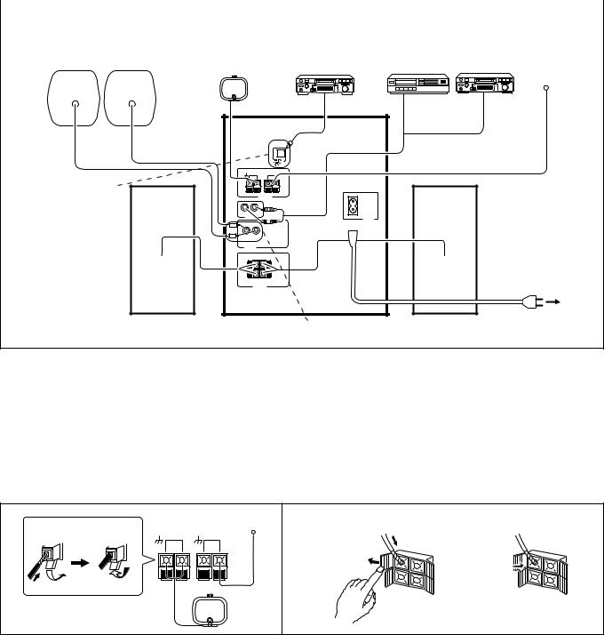
1. Connect AM loop antenna and FM antenna to the unit's antenna terminals.
1 Twist the wire strands.
2 Push away the tab and insert the cord into the terminal. 3 Pull back the tab. Be sure to tighten the cords firmly.
7Mettez l'appareil hors tension et retirez le cordon d'alimentation de la prise de courant avant d'effectuer
ou de modifier les raccordements.
÷N’oubliez pas de raccorder l’antenne, sinon la réception de programmes sera impossible.
÷Reportez-vous également à la page 10, “CONNEXIONS D’ANTENNE”.
1. Raccordez l'antenne cadre AM et l'antenne FM aux bornes d'antenne de l'appareil.
1 Torsadez les fils.
2 Repoussez le taquet et introduisez le cordon dans la borne. 3 Remettez le taquet et veillez à bien serrer les cordons.
1 |
|
|
|
2 |
2 |
2 |
3 |
AM |
FM |
1 |
|
LOOP |
UNBAL |
|
|
||
|
|
ANTENNA |
75Ω |
|
|
2.Connect the speaker cords to the FRONT SPEAKERS terminals.
Connect the red cords to the “+” (red) terminals and the black cords to the “–” (black) terminals.
1 Open the tab and insert the cord into the terminal. 2 Close the tab. Be sure to tighten the cords firmly.
2. Reliez les cordons de liaison aux enceintes aux bornes FRONT SPEAKERS.
Connecter les fils rouges à la borne “+” (rouge) et les noirs à la borne “–” (noir).
1 Ouvrez le taquet et introduisez le cordon dans la borne. 2 Refermez le taquet et veillez à bien serrer les cordons.
3. Connect the speaker connector.
Connect the red cords to the “+” (red) terminals and the black cords to the “–” (black) terminals.
3. Branchez le connecteur de chaque enceinte.
Connecter les fils rouges à la borne “+” (rouge) et les noirs à la borne “–” (noir).
8
En/Fr
CONNECTIONS
NOTES:
÷ Do not allow the conductors of the cords to project out of the terminals or to come into contact with other conductors. A breakdown or failure may occur when conductors touch.
÷Combine S-A370 together with XR-A370 only.
÷These speaker systems are not magnetically shielded, and may cause color noise or distortion when placed very near a television set. If this occurs, place the speakers farther away from the
television set. (Precaution for S-A670)
÷ Do not place any items on top of speaker system.
Speaker impedance
Connect speaker systems with a nominal impedance ranging from 6 Ω to 16 Ω.
Precaution for S-A370 and S-A670 :
Do not connect these speaker systems to any amplifier other than the one supplied with these systems. Connection to any other amplifier may result in a malfunction or a fire.
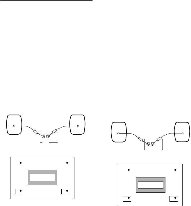
Rear speaker system connection (XR-A670 only)
÷Make sure you connect the plugs properly.
÷Rearspeakersequippedwithapinplugandwithnominalimpedance of 16 Ω or more can be connected.
R L
REAR
SPEAKERS
Rear speaker installation example
Front speaker (L) |
Front speaker (R) |
||||
|
|
|
|
|
|
Listening area
Rear speaker (L) |
Rearspeaker (R) |
When mounting rear speaker system on a wall
÷Use the hole located on the rear panel of the speaker to mount it on a wall.
Make sure the speakers are securely fixed to the wall.
÷Check if the wall is strong enough to support the speakers. PIONEER disclaims any & all responsibility for damage due to falling speakers and/or other accidents, which are caused by insufficient wall strength or any improper installation.
÷No screws or other fittings are supplied to mount the speakers on the wall.
|
RACCORDEMENTS |
|
|||
REMARQUES: |
|
|
|||
English |
|||||
÷ |
Ne combinez le S-A370 qu’avec le XR-A370. |
||||
÷ |
Faites en sorte que les conducteurs des fils ne sortent pas des |
|
|||
|
bornes et évitez tout contact avec d'autres conducteurs. Si les |
|
|||
|
conducteurs se touchent, vous risquez des pannes ou des |
|
|||
|
dysfonctionnements. |
|
|||
÷ Ces enceintes acoustiques ne sont pas magnétiquement blindées |
|
||||
|
et elles peuvent donc causer des parasites ou une distorsion des |
|
|||
|
couleurs si elles sont placées près d’un téléviseur. Dans ce cas, |
|
|
||
|
|
Français |
|||
|
séparez les haut-parleurs et le téléviseur. |
|
|||
(Précaution pour le S-A670) |
|
||||
|
|
||||
÷ Ne placez rien sur le système d'enceintes. |
|
|
|||
Impédance des enceintes |
|
|
|||
Raccordez des systèmes d'enceinte avec une impédance nominale |
|
|
|||
de 6 Ω à 16 Ω. |
|
|
|||
|
|
||||
Précautions pour le S-A370 et S-A670 :
Ne reliez pas ces enceintes à un amplificateur autre que celui fourni avec elles. Dans le cas contraire, vous pourriez constater une anomalie de fonctionnement ou même provoquer un incendie.
Raccordement du système d'enceintes arrière (seulement XR-A670)
÷Raccordez correctement les fiches.
÷Des enceintes arrière équipées d'une prise à broches et à impédance nominale de 16 Ω ou plus peuvent être connectées.
R L
REAR
SPEAKERS
Exemple d'installation des enceintes arrière
Enceintefrontale(gauche) |
Enceinte frontale (droite) |
||||
|
|
|
|
|
|

 ZonListeningd’écoutearea

Enceinte arrière (gauche) |
Enceinte arrière (droite) |
Si vous accrochez les enceintes arrière au mur
÷Servez-vous du trou dans le panneau arrière pour accrocher l'enceinte au mur.
Vérifiez que les enceintes sont fermement fixées au mur.
÷Vérifiez que le mur est suffisamment solide pour supporter les enceintes. PIONEER décline toute responsabilité quant aux dommages encourus suite à la chute des enceintes et/ou d’autres incidents causés par une solidité insuffisante du mur ou une installation inadéquate.
÷Les vis et chevilles de montage ne sont pas fournis.
9
En/Fr

CONNECTIONS
4.When using a video cassette recorder or MD player, connect a separately sold stereo audio cord to the AUX input jacks.
RACCORDEMENTS
4.Si vous utilisez un magnétoscope ou un lecteur de Minidisc, raccordez un cordon audio stéréo vendu séparément aux entrées AUX.
OUT
L
R
L |
L |
|
R |
R |
R L |
AUX IN
5.Lastly, plug the power cord into the AC wall outlet.
NOTE:
Insert the plugs securely into the jacks. Improper connection can lead to sound distortion or malfunction.
Optical digital jack connection
(The XR-A370 does not feature an optical digital jack so this connection cannot be made.)
|
OPTICAL |
|
DIGITAL |
|
IN |
|
MD |
OPTICAL |
|
DIGITAL |
DAT |
OUT |
|
|
Connecting to a component (DAT, MD etc.) that has an optical digital input jack.
÷Connect the optical output jack of the unit to the optical input jack of the connecting component with an optical cable.
÷A separately sold optical cable is used for optical digital jack connection. However, only components having the same type of optical jack as this unit can be connected with this type of cable. An adapter for digital hookup with a coaxial digital terminal is also available separatly.
5.Pour terminer le raccordement, branchez le cordon d’alimentation à la prise de courant.
REMARQUE :
Introduisez bien les fiches dans les prises jack. Un raccordement inadéquat peut provoquer une distorsion du son ou des dysfonctionnements.
Raccordement sur prise jack pour entrée optique numérique
(Le modèle XR-A370 ne possède pas de prise optique pour signaux numériques, par conséquence ce raccordement ne peut pas être effectué.)
|
OPTICAL |
|
DIGITAL |
|
IN |
|
MD |
OPTICAL |
|
DIGITAL |
DAT |
OUT |
|
|
R*Raccordement à un composant (DAT, MD, etc.) sans entrée optique numérique
÷Raccordez la sortie optique de l’appareil à l’entrée optique du composant à raccorder avec un câble en fibre optique.
÷Un câble en fibre optique vendu séparément est utilisé pour le raccordement à une prise jack optique numérique. Seuls les composants possédant le même type de jack optique que cet appareil peuvent être raccordés avec ce type de câble. Un adaptateur de raccordement numérique avec borne numérique coaxiale est également disponible séparément.
ANTENNA CONNECTIONS
Radio reception is not possible unless the antenna is properly connected.
Reception varies from one area to another. Signal broadcast tends to be especially poor in metropolitan areas where there are many tall buildings and in mountainous areas. Proper antenna installation is vital to good reception.
FM ANTENNA
A FM antenna
Fully extend the antenna and affix it to a wall, etc.
B External FM antenna installation
Use an external antenna when the signals from the stations are weak and cannot be picked up with the supplied FM antenna. If the sound heard is accompanied by too much noise, connect a 75 Ω coaxial cable.
10
CONNEXIONS D’ANTENNE
La réception radio n’est pas possible si l’antenne n’est pas correctement raccordée.
La réception varie d’une région à l’autre. La transmission du signal a tendance à être particulièrement mauvaise dans les zones métropolitaines comptant beaucoup d’immeubles élevés et dans les zones montagneuses.
ANTENNE FM
A Antenne FM
Déployez entièrement l’antenne et fixez-la à un mur etc.
B Installation de l’antenne externe FM
Utilisez une antenne extérieure quand les signaux en provenance des stations sont faibles et ne peuvent pas être captés avec l’antenne FM fournie. Utilisez un câble coaxial 75 Ω si le son entendu s’accompagne de beaucoup de bruit.
En/Fr
CONNECTIONS RACCORDEMENTS
A |
|
B |
|
|
AM |
FM |
AM |
FM |
Connect the shield wire to (signal earth). |
LOOP |
UNBAL |
LOOP |
UNBAL |
Reliez la tresse de masse à la borne (masse |
ANTENNA |
75Ω |
|||
|
|
|
||
|
|
ANTENNA |
75Ω |
signal). |
|
|
|
|
AM ANTENNA |
|
ANTENNE AM |
a |
b |
c |
not supplied non fourni
The antenna should be placed at a distance from the unit, and should not be allowed to touch metallic objects. Avoid placing it near CD players, personal computers, television sets and other devices generating radio frequencies.
÷Place the antenna on a level surface and rotate it to find the orientation that yields the best reception.
Setting up the AM antenna
There are three ways of setting up the AM antenna: (See illustration a, b and c)
a:Fasten with a pin to the wall.
b:Stand the antenna up by itself.
c:Support with a ball pen or the like (not supplied).
L’antenne doit être placée à bonne distance de l’appareil et ne doit être au contact d’aucun objet métallique. Evitez de la placer près de lecteurs de CD, d’ordinateurs familiaux, d’appareils de télévision et autres appareils produisant des fréquences radio.
÷Posez l’antenne sur une surface horizontale et tournez-la jusqu’à ce que la réception soit aussi bonne que possible.
Installation de l'antenne AM
Il existe trois façons d'installer l'antenne AM: (Voir les illustrations a, b et c)
a:Fixez l’antenne sur un mur au moyen d’une punaise.
b:Dressez l’antenne.
c:Maintenez l’antenne à l’aide d’un crayon ou d’un objet similaire. (non fourni)
External AM antenna |
Antenne externe AM |
AM loop antenna
Antenne cadre AM
Indoor AM antenna |
Outdoor AM antenna |
Antenne intérieure AM |
Antenne extérieure AM |
AM |
FM |
LOOP |
UNBAL |
ANTENNA |
75Ω |
Français English
Indoor AM antenna:
Use a vinyl-coated wire 5-6 meters (15-18 feet) long. Secure one end to the AM terminal and the other end to a wall or other high location.
Outdoor AM antenna:
If reception is still poor even when a lead antenna has been fully extended indoors, stretch out a vinyl-coated wire and secure it outdoors.
NOTE:
Do not detach the AM loop antenna when using the external AM antenna.
The  (signal earth) helps reduce noise when an antenna is connected. It is not a safety earth.
Antenne intérieure AM
Utilisez un fil gainé de vinyle (5 à 6 mètres de long). Fixer l’une des extrémités sur la borne AM et l’autre extrémité sur le mur ou un autre endroit en hauteur.
Antenne extérieure AM
Si malgré une antenne intérieure, la qualité de la réception n’est pas suffisamment bonne, un fil isolé avec du vinyle doit être installé à l’extérieur.
REMARQUE:
Conservez l’antenne cadre AM branchée lors de l’utilisation d’une antenne AM intérieure ou extérieure.
Le symbole (masse signal) contribue à réduire le bruit quand on a raccordé une antenne. Il ne s’agit pas d’une mise à la masse pour la sécurité.
11
En/Fr
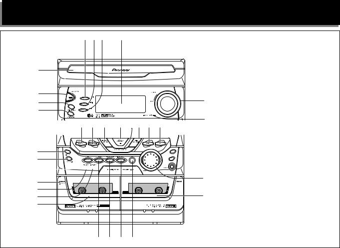
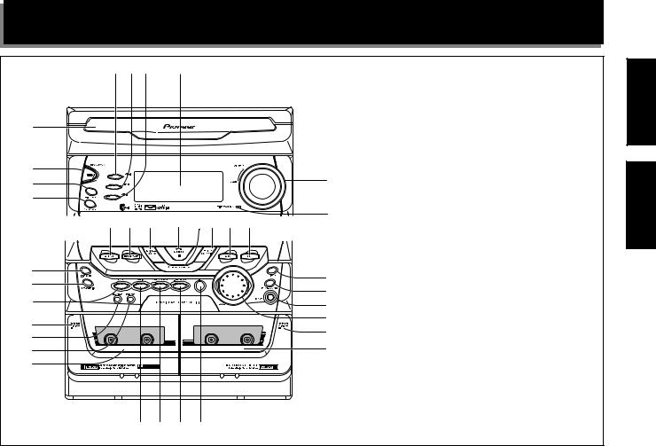
NAMES AND FUNCTIONS OF PARTS
1 2 3 |
4 |
5
The illustration shows XR-A670.
6 |
|
7 |
9 |
|
|
8 |
|
% $ # @ !~ = - |
0 |
|
^ |
UND |
MORPHI |
NG |
J |
|
|
|||
|
SO |
|
|
OG |
&
*

(
)
_
+
¡ ™ £ ¢
1 DISC-1 select button & indicator
2 DISC-2 select button & indicator
3 DISC-3 select button & indicator
4 Display
5 CD disc tray
6 STANDBY/ON switch
<TURNING ON THE POWER>
÷When the power plug is connected to an AC wall outlet, the unit enters the demonstration mode. Press the Power button to cancel the demonstration mode.
Press the STANDBY/ON switch .
To switch the power OFF (STANDBY):
Press the STANDBY/ON switch. “GOOD BYE” is displayed. Standby indicator lights.
7 DISC CHANGE button
8 OPEN/CLOSE button (Also switches power on if in standby.)
9 Volume control (VOLUME)
0 TIMER STANDBY indicator
- CD function button (Also switches power on if in standby.)
=AUX function button (Also switches power on if in standby. If the auxiliary component is already playing, then you'll hear it.)
~ TUNING + ¡ • ¢ button *(17, 20, 21, 26, 27)
!PLAY/PAUSE button *( 20, 21, 26, 27)
(Also switches power on if in standby.)
@ STOP/ST.MEMORY button *(18, 20, 21, 26, 27)
# TUNING – 4 • 1 button *(17, 20, 21, 26, 27)
$TUNER/BAND function button
(Also switches power on if in standby.)
%TAPE I/II function button
(Also switches power on if in standby.)
^XR-A370 : REPEAT button
XR-A670 : Dolby** 2NR ON/OFF button
& FREQ/STATION button
12


 º
º


 ª
ª
 •
•
¶

 § 7 Auto Play Function
If you press the CD function button when a CD is
loaded, the CD automatically starts playing. If you press the TAPEI/II function button when a tape is
loadedinthecassettedeck,thetapeautomatically starts playing.
NOTE:
You cannot change the function during recording and tape copying.
* PRESET button
( TAPE I Eject button (0) ) REC/STOP button
_ ASES/COPY button + TAPE I cassette door ¡ EQUALIZER button
™ ZOOM SURROUND button £ P.BASS (DEMO) button
¢ SET button
TAPE II cassette door § TAPE II Eject button (0)
¶ SOUND MORPHING JOG (S. M. JOG)
• PHONES jack (Headphones) ª TIMER/CLOCK ADJ button º DISPLAY button
*
÷The functions of some buttons changes depending on the input. To learn about the different functions see the page numbers in parenthesis.
**
÷Dolby noise reduction manufactured under license from Dolby Laboratories Licensing Corporation.
÷“DOLBY” and the double-D symbol are trademarks of Dolby Laboratories Licensing Corporation.
En/Fr
NOMS ET FONCTIONS DES PIECES
1 2 3 |
4 |
5 |
|
|
|
|
L'illustration montre la XR-A670. |
|
6 |
|
|
|
|
|
|
7 |
|
|
|
|
9 |
|
|
|
|
|
|
|
|
8 |
|
|
|
|
|
|
|
% $ # @ !~ = - |
0 |
|
|||
|
|
|
||||
^ |
UND |
MORPHI |
NG |
J |
|
|
|
|
|
|
|||
|
SO |
|
|
OG |
º |
|
& |
|
|
|
|
|
|
|
|
|
|
ª |
|
|
* |
|
|
|
|
|
|
|
|
|
|
• |
7 Fonction de lecture automatique |
|
|
|
|
|
|
||
|
|
|
|
|
¶ |
|
( |
|
|
|
|
Si vous appuyez sur la touche CD de sélection du |
|
|
|
|
|
§ |
||
) |
|
|
|
|
lecteur de CD alors qu’un CD est en place dans l’appareil, |
|
|
|
|
|
|
sa lecture commence aussitôt. Pareillement, Si vous |
|
_ |
|
|
|
|
|
|
|
|
|
|
appuyez sur la touche TAPEI/II de sélection de la platine |
||
+ |
|
|
|
|
|
|
|
|
|
|
|
à cassette alors qu’une cassette est en place dans |
|
|
|
|
|
|
|
|
|
|
|
|
|
|
l’appareil, sa lecture commence aussitôt. |
|
|
|
|
|
|
REMARQUE : |
|
|
|
|
|
|
Vous ne pouvez pas changer de fonction pendant |
|
¡ ™ £ ¢ |
|
|
|
|
l'enregistrement et la copie d'une cassette. |
|
|
|
|
|
|
|
1 Touche et témoin de sélection DISC-1
2 Touche et témoin de sélection DISC-2
3 Touche et témoin de sélection DISC-3
4 Ecran d'affichage
5 Plateau de disque CD
6 Touche STANDBY/ON
<METTRE L'APPAREIL SOUS TENSION>
÷Lorsque la fiche est introduite dans la prise de courant, l'appareil passe en mode démonstration. Appuyez sur la touche POWER pour mettre fin au mode démonstration.
Appuyez sur l'interrupteur STANDBY/ON .
Pour mettre l'appareil hors tension (STANDBY):
Appuyez une deuxième fois sur l'interrupteur STANDBY/ON. Les mots “GOOD BYE” apparaissent.
Le témoin de veille s’éclaire.
7 Touche DISC CHANGE
8 Touche ouvrir/fermer (OPEN/CLOSE)
(Met aussi l'appareil sous tension s'il est en attente.)
9 Réglage volume (VOLUME)
0 Témoin TIMER STANDBY
-Touche de sélection CD
(Met aussi l'appareil sous tension s'il est en attente.)
= Touche de sélection AUX
(Met aussi l'appareil sous tension s'il est en attente. Si la lecture a déjà commencé sur les composants auxiliaires, ils seront audibles.)
~ Touche TUNING + ¡ • ¢ *(17, 20, 21, 26, 27) ! Touche PLAY/PAUSE *( 20, 21, 26, 27)
(Met aussi l'appareil sous tension s'il est en attente.)
@ Touche STOP/ST.MEMORY *(18, 20, 21, 26, 27)
# Touche TUNING – 4• 1 *(17, 20, 21, 26, 27)
$Touche de sélection TUNER/BAND
(Met aussi l'appareil sous tension s'il est en attente.)
%Touche de sélection TAPE I/II
(Met aussi l'appareil sous tension s'il est en attente.)
^XR-A370 : Touche REPEAT
XR-A670 : Touche Dolby** 2NR marche/arrêt (ON/OFF)
& Touche FREQ/STATION * Touche PRESET
( Touche d'éjection TAPE I (0)
) Touche enregistrement/arrêt (REC/STOP) _ Touche ASES/COPY
+ Volet cassette TAPE I ¡ Touche EQUALIZER
™ Touche ZOOM SURROUND £ Touche P.BASS (DEMO) ¢ Touche SET
Volet cassette TAPE II
§ Touche d'éjection TAPE II (0)
¶ SOUND MORPHING JOG (S. M. JOG)
• Prises jack casques (PHONES) ª Touche TIMER/CLOCK ADJ º Touche DISPLAY
*
÷La fonction de certaines touches varie selon l'entrée. Pour les informationssur lesdifférentesfonctions, consultez lenuméro de page indiqué entre parenthèses ().
**
÷Réduction de bruit Dolby fabriquée sous licence de Dolby Laboratories Licensing Corporation.
÷DOLBY et le symbole double-D sont des marques de Dolby Laboratories Licensing Corporation.
13
Français English
En/Fr
NAMES AND FUNCTIONS OF PARTS |
|
NOMS ET FONCTIONS DES PIECES |
~ |
! @ |
1 |
2 |
3 4 5 |
= |
|
|
|
6 |
|
|
|
|
7 |
- |
|
|
|
|
0 |
|
|
|
|
|
9 |
|
|
8 |
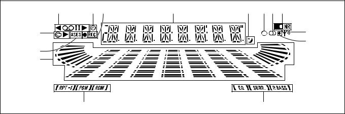
Display section |
|
|
Section affichage |
|
|
|
|
|
1 Displays a wide range of operation status indications.
2 Lights during Sleep Timer operation.
3 Lights when the MONO mode is selected.
4 Lights during FM stereo reception.
5 Lights when Dolby NR is on. (XR-A670 only) 6 Indicates tuner reception status.
7 Lights when BEAT CUT 2 is selected. (XR-A670 only) 8 Indicates SOUND MORPHING status.
9 Indicates CD function status.
0 Indicates Audio level.
- Lights during ASES operation. = Indicates CD play status.
~ Indicates TAPE play status.
! Displays timer function indications. @ Lights during recording.
1Affiche diverses indications relatives au fonctionnement.
2Ce témoin s’éclaire pendant le fonctionnement du programmateur de mise hors service.
3 Ce témoin s'éclaire quand le mode MONO est sélectionné.
4 Ce témoin s'éclaire pendant la réception FM stéréo.
5Ce témoin s'éclaire quand Dolby NR est activé. (XR-A670 seulement)
6 Indique les conditions de réception du syntoniseur.
7Ce témoin s’éclaire lorsque vous choisissez BEAT CUT 2. (XR-A670 seulement)
8Indique les conditions de la correction SOUND MORPHING.
9 Indique les conditions du lecteur de CD.
0 Ceci indique le niveau sonore.
- Ce témoin s’éclaire pendant l’usage de la fonction
ASES.
= Indique l'état de lecture du CD.
~ Indique l'état de lecture de la cassette (TAPE).
! Affiche les informations relatives au programmateur. @ Ce témoin s’éclaire pendant un enregistrement.
14
En/Fr

|
NAMES AND FUNCTIONS OF PARTS |
NOMS ET FONCTIONS DES PIECES |
|||
REMOTE CONTROL UNIT |
|
|
|
|
|
TELECOMMANDE |
1 |
|
|
|
- |
|
2 |
1 |
2 |
3 |
= |
|
|
|
|
||
3


 ~
~
4 |
! |
|
|
|
|
|
|
|
|
5 |
@ |
|
|
|
6 |
# |
|
|
|
7 |
$ |
|
|
|
|
|
|
|
|
8 |
|
|
|
|
9 |
% |
|
|
|
0 |
|
|
|
|
|
|
|
|
|
|
^ |
Operations indicated by the [ |
] mark |
are |
|
performed with the remote control unit. |
|
||
|
|
|
||
|
|
Les opérations indiquées par le symbole [ |
] |
|
|
|
s'effectuent avec la télécommande. |
|
|
1 DISC select buttons (1-3)
2 DISC CHANGE button
3 OPEN/CLOSE button
4 Digit (1-9, 10/0, >10) buttons
5BAND button
Use to switch between FM and AM bands. 3 FM
AM 2
6 TAPE I / II function button
7 RDM button
8 RPT button
9 MONO button
0 DISP button
- STANDBY / ON button
= SLEEP button
~ PGM button
! CLEAR button
@ AUX function button
# CD function button
$ CD/TAPE/STATION (up, down) operation buttons
¶ CD operation buttons
(Play/Pause 6 , Track search 4 ¢, Stop 7, Fast 1 ¡)
¶ TAPE operation buttons
(Play 2 ,3Music Search 4 ¢, Stop 7, Fast 1 ¡) (The XR-A370 do feature the Music Search 4 ¢function.)
¶TUNER buttons
+ ....... Move to the next station.
– ........ Move to the previous station. 1.... Frequency down.
¡.... Frequency up.
%VOLUME 5(up), (down) buttons
^SOUND MORPHING MODE button & SOUND MORPHING JOG control buttons
1 Touches de sélection DISC (1-3)
2 Touche DISC CHANGE
3 Touche ouvrir/fermer (OPEN/CLOSE)
4 Touches numériques (1-9, 10/0, >10)
5Touche BAND
Pour faire commuter les bandes FM et AM. 3 FM
AM 2
6 Touche de fonction TAPE I / II
7 Touche RDM
8 Touche répétition (RPT)
9 Touche MONO
0 Touche affichage (DISP)
- Touche mise sous tension (STANDBY/ON)
= Touche minuterie arrêt automatique (SLEEP)
~ Touche programme (PGM)
! Touche effacer (CLEAR)
@ Touche de fonction AUX
# Touche de fonction CD
$ Touchesd'opérationCD/TAPE/STATION(avance,recul)
¶ Touches d'opération CD
(Lecture/Pause 6 , Recherche piste 4 ¢, Arrêt 7, Balayage rapide 1 ¡)
¶ Touches d'opération TAPE (cassette)
(Lecture 2 ,3Recherche chanson 4 ¢, Arrêt 7, Balayage rapide 1 ¡)
(Le modèle XR-A370 ne possède pas la touche de recherche de plage musicale 4 ¢.)
¶ Touches TUNER
+....... Passe à la station suivante.
– ....... Passe à la station précédente. 1.... Fréquence plus haute.
¡.... Fréquence plus basse.
%Touches VOLUME 5(augmenter), (diminuer)
^ Touche SOUND MORPHING MODE et touches de
commande SOUND MORPHING JOG
15
Français English
En/Fr
 Loading...