


POWERED SUBWOOFER
ENCEINTE ACTIVE D'EXTREMES GRAVES
AKTIVER SUBWOOFER
SUBWOOFER, ALTOPARLANTE PER TONI BASSI,
ALIMENTATO
SUBWOOFER MET SPANNINGSCIRCUIT STRÑMFÑRSÑRJD BASHÑGTALARE
ALTAVOCES DE GRAVES SECUNDARIOS ENERGIZADOS ALTIFALANTE DE SUBGRAVES DE POTÊNCIA
S-W110S-QL S-W110S-K S-W150S
Operating Instructions
Mode d´emploi
Bedienungsanleitung
Istruzioni per l´uso
Gebruiksaanwijzing
Bruksanvisning
Manual de instrucciones
Manual de instruções

Thank you for buying this PIONEER product. Please read through these operating instructions so you will know how to operate your model properly. After you have finished reading the instructions, put them away in a safe place for future reference. In some countries or regions, the shape of the power plug and power outlet may sometimes differ from that shown in the explanatory drawings. However, the method of connecting and operating the unit is the same.
Nous vous remercions pour cet achat d’un produit PIONEER. Nous vous demandons de lire soigneusement ce mode d’emploi; vous serez ainsi à même de faire correctement fonctionner l’appareil. Après avoir bien lu le mode d’emploi, le ranger dans un endroit sûr pour pouvoir s’y référer ultérieurement.
Dans certains pays ou certaines régions, la forme de la fiche d’alimentation et de la prise d’alimentation peut différer de celle qui figure sur les schémas, mais les branchements et le fonctionnement de l’appareil restent les mêmes.
2
En/Fr

ACCESSORY ITEMS/ACCESSOIRES FOURNIS
÷ Speaker cords x 2 |
÷ RCA plug cord x 1 |
÷ Operating instructions x 1 |
÷ Warranty card x 1 |
÷ Câbles pour haut-parleur x 2 |
÷ Câble à prise RCA x 1 |
÷ Mode d’emploi x 1 |
÷ Fiche de garantie x 1 |
FEATURES
7110 W (S-W110S-QL, S-W110S-K), 150W (S-W150S) power that serves video software playback such as Dolby* Digital with a wide dynamic range.
7Equipped with 22 cm driver
7Turnover frequency can be continuous (50 – 200Hz).
7Phase conversion switch (0°/180°).
72 systems consisting of an input that connects to the amplifier's speaker terminals and an input that connects to the SUBWOOFER PRE-OUT terminal.
*Maunfactured under license from Dolby Laboratories. ”Dolby” and the double-D symbol are trademarks of Dolby Laboratories. Confidential unpublished works. © 1992-1997 Dolby Laboratories. All rights reserved.
IN COMBINATION WITH SPEAKERS
The frequency characteristics of the S-W110S-QL/S-W110S- K/S-W150S combined with small-size speakers are shown below. As shown in these figures, the low frequency range is improved.
÷These special characteristics are obtained in an echoless chamber. The effect of an additional S-W110S-QL/S- W110S-K/S-W150S in an ordinary listening room is better than the chart indicates when positioned adequately.
Small-size speakers + S-W110S-QL/S-W110S-K/S-W150S
(dB) |
|
RESPONCE |
Small-size speaker |
|
FREQUENCY (Hz)
÷With playback of Dolby* Digital, establishment of a special channel for the subwoofer is recommended; and with playback of LFE (Low Frequency Effect: sound effect like the rumbling of the earth, whose purpose is to intensify the force of the video), the S-W110S-QL/S-W110S-K/S- W150S is especially effective.
Dolby* Digital
Dolby Digital is the name of the Dolby Surround multi-channel digital system that was developed from Dolby Surround, as a continuation of Dolby Pro Logic Surround.
Dolby Digital is also referred to as a 5.1 channel system. This is because it has 5 channels in the 20Hz – 20kHz frequency range (front left and right, center, and rear left and right) and an independent channel for the subwoofer. The subwoofer channel is also referred to as LFE (Low Frequency Effect).
The LFE channel is used according to individual tastes to enhance the bass effect.
CARACTERISTIQUES
7Puissance de 110 W (S-W110S-QL, S-W110S-K), 150W (S- W150S) permettant la reproduction de programmes vidéo, tels que les programmes Dolby* Digital, avec une gamme dynamique étendue.
7Equipé d’un amplificateur de 22 cm
7Fréquence de transition à réglage continu (50 – 200 Hz)
7Convertisseur de phase (0°/180°)
7Système à 2 circuits, constitué d’une entrée pouvant être reliée aux bornes haut-parleurs d’un amplificateur et d’une entrée reliée à la borne de sortie SUBWOOFER PRE-OUT.
*Fabriqué sous licence de Dolby Laboratories. "Dolby" et le symbole double D sont des marques de commerce de Dolby Laboratories. Œuvres confidentielles non publiées. © 1992-1997 Dolby Laboratories. Tous droits réservés.
UTILISATION COMBINEE AVEC DES ENCEINTES ACOUSTIQUES
Les caractéristiques de fréquence du S-W110S-QL/S- W110S-K/S-W150S lorsqu’il est utilisé en combinaison avec des enceintes acoustiques de petite taille sont indiquées cidessous. Comme on peut le voir sur ce graphique, la gamme des basses fréquences est sensiblement améliorée.
÷Ces caractéristiques spéciales sont obtenues dans une chambre sans écho. L’effet produit par l’ajout d’un S- W110S-QL/S-W110S-K/S-W150S dans une salle d’écoute ordinaire est supérieur à l’effet indiqué sur le graphique, à condition que le subwoofer soit correctement placé.
Enceinte de petite taille + S-W110S-QL/S-W110S-K/S-W150S
(dB) |
|
REPONSE |
Enceinte de petite taille |
|
FREQUENCE (Hz)
÷Il est recommandé de réserver une voie spéciale pour le subwoofer en cas de reproduction d’un programme Dolby* Digital. Le S-W110S-QL/S-W110S-K/S-W150S est particulièrement efficace en cas de reproduction d’un effet LFE (effet de basse fréquence : un effet sonore similaire au grondement de la terre qui a pour objet d’identifier la force de la vidéo).
Dolby* Digital
Dolby Digital est une expression désignant un système sonore numérique Dolby à voies multiples qui a été développé à partir du système sonore Dolby pour succéder au système sonore Dolby Pro Logic.
Le système Dolby Digital est un système parfois dit à 5.1 voies parce qu’il offre 5 voies dans la gamme de fréquence 20 Hz à 20 kHz (avant gauche et droite, centre, arrière gauche et droite) et une voie indépendante pour le subwoofer. La voie du subwoofer est également appelée voie LFE (effet de basse fréquence).
La voie LFE peut être utilisée selon les goûts personnels de chacun pour renforcer les sons graves.
3
Português Español Svenska Nederlands Italiano Deutsch Français English
En/Fr

INSTALLATION |
|
INSTALLATION |
|
A |
B |
2 |
|
|
|
||
1 |
2 |
1 |
3 |
|
|
||
|
|
4 |
|
3 |
|
5 |
|
4 |
|
6 |
7 |
|
|
Speaker Installation |
|
Installation des enceintes |
|
|
|
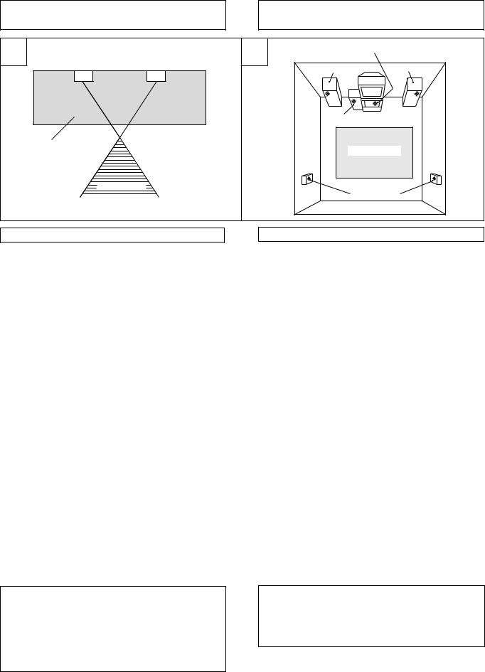
The subwoofer plays back the bass in monaural, making use of the fact that the human ear loses the sense of direction of lowpitched sound. Since the sense of direction is lost, the subwoofer can be installed almost anywhere. If it is installed too far away, however, the sound from the left and right speakers may become unnatural.
÷ Subwoofer Installation Criteria (Å)
1Left speaker 2 Right speaker
3 Recommended installation range for the subwoofer
4 Listening position
÷An example of speaker positioning (ı)
1Front left speaker
2 Center speaker
3 Front right speaker
4 Subwoofer
5 Listening area
6 Rear left speaker
7 Rear right speaker
NOTE:
÷To avoid interference with the picture on a nearby TV set, use magnetically shielded speaker systems. This is particularly important for the center speaker since it is usually located closest to the TV.
÷Position the left and right channel speakers at equal distances from the TV set and approximately 1.8 meters from each other.
÷Install the center speaker above or below the TV so that the sound of the center channel is localized at the TV screen.
÷The rear (surround) speakers are most effective when installed in parallel locations directly to the side, or slightly behind, the listener, at a level about 1 meter above the listener's ears.
CAUTION:
When installing the center speaker on top of the TV, be sure to secure it with tape or some other suitable means. Otherwise, the speaker may fall from the TV due to external shocks such as earthquakes, and it may lead to endangering those nearby or damaging the speaker.
4
En/Fr
Du fait que l’oreille humaine n’est pas capable de percevoir la direction des sons graves, le subwoofer reproduit les sons graves en monophonie. De ce fait, il est possible de l’installer pratiquement n’importe où. A noter, cependant, que lorsqu’il est installé trop loin, le son provenant de l’enceinte droite et de l’enceinte gauche peut être déformé.
÷Critères d’installation du subwoofer (Å)
1 Enceinte gauche
2 Enceinte droite
3 Position préconisée pour le subwoofer 4 Position d’écoute
÷Emplacements types des enceintes (ı)
1 Enceinte avant gauche
2 Enceinte centrale
3 Enceinte avant droite
4 Subwoofer
5 Zone d’écoute
6 Enceinte arrière gauche
7 Enceinte arrière droite
REMARQUES:
÷Pour éviter toute perturbation des images du récepteur de télévision, utiliser des enceintes à écran magnétique. Ceci est plus particulièrement important dans le cas de l’enceinte centrale du fait qu’elle est toujours la plus proche du récepteur de télévision.
÷Placer l’enceinte droite et l’enceinte gauche à égale distance du récepteur de télévision et à environ 1,8 mètre l’une de l’autre.
÷Installez l’enceinte centrale au-dessus ou en dessous du téléviseur, de façon à ce que le son du canal central provienne de l’écran du téléviseur.
÷Les enceintes arrière (ambiophoniques) donnent les meilleurs résultats lorsqu’elles sont placées de manière symétrique par rapport à la position d’écoute, au même niveau ou légèrement derrière, et à environ 1 mètre au-dessus du niveau des oreilles d’une personne assise.
ATTENTION:
Si vous installez l‘enceinte centrale sur le téléviseur, assurezvous de le fixer avec du ruban adhésif ou par un autre moyen. Sinon, l‘enceinte risque de tomber à cause de chocs extérieurs à l‘appareil, comme des tremblements de terre, et vous pourriez mettre en danger les personnes à proximité ou l‘enceinte pourrait être endommagée.

INSTALLATION
Installation Precautions
÷Install the unit in a well-ventilated location where it will not be exposed to high temperatures and high humidity.
÷Do not place the unit near stoves or other heating equipment or at locations exposed to direct sunlight, as these can have an adverse effect on the cabinet and internal components. Also, do not install the unit where there is too much dust or high humidity, as these can cause malfunctioning or breakdowns. (Avoid cooking tables and other locations where the unit would be exposed to heat, steam and soot.)
÷Do not place heavy objects such as a television or TV monitor on top of the unit.
÷Keep the unit away from devices such as cassette decks which are sensitive to magnetic fields.
This speaker system is magnetically shielded.
However, depending on the installation location, color distortion may occur if the speaker system is installed extremely close to the screen of a television set.
If this happens, turn off the power switch of the television set, and turn it on after 15 to 30 minutes.
If the problem persists, place the speaker system away from the television set.
÷Please install this unit away from the antenna cable of the tuner, as noise can be caused with installation close to the antenna cable. In such a case, use this unit at a position away from the antenna and the antenna cable, or when playback of extra bass is not required, switch off the power for this unit.
VENTILATION
When installing this unit, make sure to leave space around the unit for ventilation to improve heat radiation (at least 60 cm at the top, 10 cm at the rear, and 30 cm at each side). If not enough space is provided between the unit and walls or other equipment, heat will build up inside, interfering with performance or causing malfunctions.
WARNING: Slot and openings in the cabinet are provided
for ventilation and to ensure reliable operation of the product and to protect it from overheating, to prevent fire hazard, the openings should never be blocked and covered with items, such as newspapers, table-cloths, curtains, etc. Also do not put the apparatus on the thick carpet, bed, sofa, or fabric having a thick pile.
MAINTENANCE OF EXTERNAL SURFACES
÷Use a polishing cloth or dry cloth to wipe off dust and dirt.
÷When the surfaces are very dirty, wipe with a soft cloth dipped in some neutral cleanser diluted five or six times with water, and wrung out well, and then wipe again with a dry cloth. Do not use furniture wax or cleaners.
÷Never use thinners, benzine, insecticide sprays and other chemicals on or near this unit, since these will corrode the surfaces.
INSTALLATION
Précautions d’installation
÷Installer le subwoofer dans un endroit bien ventilé où il ne sera pas soumis à une humidité ou à des températures excessives.
÷Ne pas placer le subwoofer à proximité d’un radiateur, ou autre appareil de chauffage, et ne pas l’exposer aux rayons directs du soleil car cela risquerait d’endommager le coffret ou les composants internes. Ne pas le placer non plus dans un endroit excessivement poussiéreux ou humide car ceci pourrait provoquer des anomalies de fonctionnement ou une panne. (Eviter de le placer sur une table de cuisine ou autres emplacements où il serait soumis à la chaleur, à la vapeur ou à la suie).
÷Ne jamais placer d’objets lourds (récepteur ou moniteur de télévision par exemple) sur le subwoofer.
÷Ne pas placer le subwoofer à proximité d’un appareil, comme par exemple un magnétophone, susceptible d’être affecté par les champs magnétiques.
Cette enceinte acoustique est une enceinte à écran magnétique.
Elle risque, cependant, de provoquer des altérations de la couleur des images si elle est placée à proximité de l’écran d’un récepteur de télévision.
Si ce phénomène se produit, mettre le récepteur de télévision hors tension et attendre 15 à 30 minutes avant de le remettre sous tension.
Si le problème persiste, éloigner l’enceinte acoustique du récepteur de télévision.
÷Prière d’installer cette unité à distance du câble d’antenne du tuner, car des parasites peuvent être provoqués par une installation proche du câble d’antenne. Dans ce cas, utiliser cette unité à une position écartée de l’antenne et du câble d’antenne, ou si la reproduction de basses supplémentaires n’est pas nécessaire, couper l’alimentation de cette unité.
VENTILATION
En installant cet appareil, assurez-vous de laisser de la place autour, pour que la chaleur puisse être évacuée (au moins 60 cm au dessus, 10 cm à l’arrière et 30 cm de chaque côté). S’il n’y a pas assez de place entre l’appareil et le mur ou d’autres équipements, la chaleur s’accumule à l’intérieur, ce qui diminue les performances et cause des dysfonctionnements.
ATTENTION: Les évents et les ouvertures dans la structure
sont prévus pour la ventilation et pour assurer le bon fonctionnement du produit et pour la protéger des risques de surchauffe, et des risques d’incendie, les ouvertures ne doivent jamais etre bloquées ni couvertes par des matériaux tels que journaux, nappes, rideaux, etc. De meme, ne pas positionner l’appareil sur un tapis épais, lit, canapé ou tout meuble possédant un rembourrage épais.
ENTRETIEN DES SURFACES EXTERNES
÷Utiliser un chiffon à polir ou un chiffon sec pour éliminer la poussière et la saleté.
÷Lorsque les surfaces sont extrêmement sales, utiliser un chiffon doux et un produit détergeant neutre dilué dans cinq ou six volumes d’eau. Bien tordre le chiffon avant de nettoyer les surfaces. Les essuyer ensuite avec un chiffon sec. Ne jamais utiliser de produits de nettoyage ou de la cire pour meubles.
÷Ne jamais utiliser de diluant, benzine, bombe insecticide et autres produits chimiques à proximité de cette enceinte car ces produits détérioreraient le fini de surface.
5
Português Español Svenska Nederlands Italiano Deutsch Français English
En/Fr

PANEL FACILITIES |
|
DESCRIPTION DE LA FACE AVANT ET |
|
DE LA FACE ARRIERE |
|
|
|
A |
1 |
2 |
3 4 |
5 |
|
|
|
|
|
|
LEVEL |
TURNOVER |
S-W110S |
||
|
|
|
80 |
|
|
POWER |
|
|
|
PHASE |
|
|
65 |
|
|
120 |
|
OFF ON |
|
|
|
0∞ |
180∞ |
MIN |
MAX |
50 |
Hz |
200 |
|
|
|
|
|||
FRONT PANEL (Å) |
|
FACE AVANT (Å) |
|
|
|
1 Power Indicator |
|
1 Témoin d’alimentation (POWER) |
Illuminates when the power is on. |
|
S’allume lorsque le subwoofer est sous tension. |
2 Power switch (POWER) |
|
2 Interrupteur d’alimentation (POWER) |
When pressed, power is turned ON; when pressed again, power is turned OFF.
3 Level knob (LEVEL)
Sets the subwoofer volume.
÷Turn the knob slowly from the MIN position.
÷With this unit, the bass level can be independently set, so do not turn up the bass on the stereo amplifier.
4 Turnover knob (TURNOVER)
Sets the high limit of the frequency played back by the subwoofer. ÷ Setting Criteria
50Hz ... when the diameter of the left/right speakers is 20-cm or more. 100Hz . when the diameter of the left/right speakers is 10 – 25-cm. 200Hz . when the diameter of the left/right speakers is 12-cm or less.
5 Phase switch (PHASE — 0˚ / _ 180˚)
When depressed (_ 180˚), the output phase becomes the reverse of the input signal, and when raised (— 0˚ ), it is in the same phase as the input signal.
÷Normally, the switch is set to (— 0˚ ).
But when the sound connection between the subwoofer and the left and right speakers sounds unnatural, try switching to 180˚ and set the switch in the position where the sound is natural.
Appuyer une première fois sur ce bouton pour mettre sous tension et une deuxième fois pour mettre hors tension.
3 Bouton de réglage du volume (LEVEL)
Permet de régler le volume du subwoofer.
÷Tourner lentement le bouton à partir de la position MIN.
÷Le subwoofer permet de régler indépendamment le niveau de basse et il n’est donc pas nécessaire d’augmenter ce niveau en utilisant la commande de l’amplificateur.
4 Bouton de réglage de la fréquence de transition
(TURNOVER)
Permet de régler la limite supérieure de la fréquence de reproduction du subwoofer.
÷ Critères de réglage
50 Hz ........ Lorsque le diamètre du haut-parleur droit/gauche est égal ou supérieur à 20 cm.
100 Hz ...... Lorsque le diamètre du haut-parleur droit/gauche est compris entre 10 et 25 cm.
200 Hz ...... Lorsque le diamètre du haut-parleur droit/gauche est égal ou inférieur à 12 cm.
5 Sélecteur de phase (PHASE — 0˚ / _ 180˚)
Lorsque ce sélecteur est enfoncé (_ 180˚), la phase du signal de sortie est inverse de la phase du signal d’entrée et lorsqu’il est sorti (— 0˚), les deux signaux ont la même phase.
÷Ce sélecteur doit être normalement réglé sur (— 0˚), mais lorsque l’équilibre du son entre l’enceinte droite, l’enceinte gauche et le subwoofer ne semble pas naturel, essayer 180˚ et laisser le sélecteur à la positon donnant le résultat le plus naturel.
6
En/Fr

PANEL FACILITIES |
DESCRIPTION DE LA FACE AVANT ET DE LA FACE ARRIERE |
B |
6 7 |
8 9 |
|
|
|
R |
L |
|
LINE LEVEL |
SPEAKER |
|
OUTPUT |
LEVEL |
|
OUTPUT |
||
|
||
+ |
+ |
SPEAKER
LEVEL
INPUT
 R
R 

 L
L 
LINE LEVEL
INPUT
REAR PANEL (ı)
6 Line Level Input terminal (LINE LEVEL INPUT)
Connects to the stereo amplifier’s SUBWOOFER PRE-OUT terminal, with the specially provided RCA plug cord.
7 Line Level Output terminal (LINE LEVEL OUTPUT)
Used for connecting other equipment through the amplifier.
8 Speaker Level Output terminals
(SPEAKER LEVEL OUTPUT)
When the speakers output terminals on the stereo amplifier are connected to this unit’s SPEAKER LEVEL INPUT terminals
9and used as the unit’s input signal, these terminals are used to connect the left and right speakers via the unit.
9Speaker Level Input terminals
(SPEAKER LEVEL INPUT)
Connect to the speakers output terminals on the stereo amplifier, with the specially provided speaker cords.
FACE ARRIERE (ı)
6 Borne d’entrée de niveau de ligne (LINE LEVEL INPUT)
Permet le raccordement à la borne de sortie SUBWOOFER PREOUT d’un amplificateur stéréo au moyen du câble à prise RCA fourni.
7 Terminal de sortie niveau de ligne (LINE LEVEL
OUTPUT)
Pour raccorder d’autres appareils via l’amplificateur.
8 Bornes de sortie de niveau haut-parleur
(SPEAKER LEVEL OUTPUT)
Lorsque les bornes de sortie haut-parleur de l’amplificateur stéréo sont connectées aux bornes d’entrée de niveau hautparleur (SPEAKER LEVEL INPUT) 9 du subwoofer, et qu’elles sont utilisées pour lui transmettre les signaux d’entrée, ces bornes doivent être utilisées pour connecter l’enceinte droite et l’enceinte gauche par l’intermédiaire du subwoofer.
9 Bornes d’entrée de niveau haut-parleur
(SPEAKER LEVEL INPUT)
Ces bornes doivent être connectées aux bornes de sortie hautparleur de l’amplificateur stéréo à l’aide des câbles pour hautparleur spéciaux fournis.
7
Português Español Svenska Nederlands Italiano Deutsch Français English
En/Fr
CONNECTIONS |
RACCORDEMENTS |
||
A |
LINE LEVEL |
|
|
OUTPUT |
|
|
|
SUB WOOFER |
Supplied RCA plug cord |
+ |
+ |
|
|
||
PREOUT |
Câble à prise RCA fourni |
|
SPEAKER |
|
|
|
LEVEL |
|
|
|
INPUT |
|
|
R |
L |
|
LINE LEVEL |
S-W110S-QL/S-W110S-K/S-W150S (Rear Panel) |
|
|
INPUT |
S-W110S-QL/S-W110S-K/S-W150S (face arrière) |
|
|
|
||
Before making or changing the connections, switch off the power switch and disconnect the power cord from the AC outlet.
Couper l’alimentation et débrancher le cordon d’alimentation de la prise secteur avant de procéder au raccordement.
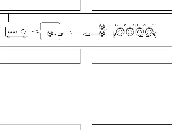
LINE LEVEL CONNECTION (Å) |
|
RACCORDEMENT DE NIVEAU DE LIGNE (Å) |
|
|
|
This connection is for a stereo amplifier or receiver equipped with a SUBWOOFER PRE-OUT terminal. If the stereo amplifier or receiver is not equipped with a SUBWOOFER PRE-OUT terminal, carry out a Speaker Level connection. Connect to the LINE LEVEL INPUT terminal on this unit, using the specially provided RCA plug cord.
NOTES:
÷When connected to the PRE-OUT terminal for surround center channel on the stereo amplifier or receiver, the bass is heard only on the center channel, so it will be insufficient.
SPEAKER LEVEL CONNECTION (ı , Ç)
This is a connection to the speaker terminals on the stereo amplifier or receiver.
NOTES:
÷When the power of the stereo amplifier is turned off before the power of this unit is switched off, a shock sound may be generated. In this case, lower the subwoofer volume or turn off the power of this unit. If the stereo amplifier has a switched outlet, connect the power cable of this unit to this outlet.
÷When the subwoofer volume is set to an extremely high level, howling may be caused when the power of the stereo amplifier is turned off or when the speaker switch is turned on. To prevent this, connect the power cable of this unit to the switched outlet of the stereo amplifier. If there is no switched outlet, lower the subwoofer volume or turn off the power of this unit before turning off the power of the stereo amplifier. Also, when using this unit at a high level, do not turn off the speaker switch of the stereo amplifier.
÷Do not turn up the bass on the stereo amplifier or receiver. If the stereo amplifier or receiver has no output margin, sound distortion is apt to occur. Adjust the bass level with the unit’s LEVEL knob.
÷When the LINE LEVEL INPUT terminal is connected, the SPEAKER LEVEL INPUT terminals cannot be used.
8
En/Fr
Raccordement à effectuer lorsque l’ampli-tuner ou l’amplificateur stéréo est équipé d’une borne de sortie SUBWOOFER PRE-OUT. Si l’ampli-tuner ou l’amplificateur stéréo n’est pas équipé d’une borne de sortie SUBWOOFER PRE-OUT, faire un raccordement de niveau haut-parleur. Relier cette borne à la borne d’entrée de niveau de ligne (LINE LEVEL INPUT) du subwoofer à l’aide du câble à prise RCA fourni.
REMARQUE:
÷En cas de raccordement à la borne PRE-OUT de l’ampli-tuner ou de l’amplificateur stéréo pour effet d’ambiophonie par la voie centrale, les sons graves ne seront perçus que sur la voie centrale, ce qui est insuffisant.
RACCORDEMENTS DE NIVEAU HAUT-PARLEUR (ı , Ç)
Il s’agit du raccordement aux bornes de haut-parleur d’un ampli-tuner ou d’un amplificateur stéréo.
REMARQUES:
÷Lorsque l’amplificateur stéréo est mis hors tension avant le subwoofer, il peut se produire un bruit de choc. Dans ce cas, baisser le volume du subwoofer ou le mettre hors tension. Si l’amplificateur stéréo est équipé d’une prise de sortie d’alimentation CA commutée, brancher le cordon d’alimentation du subwoofer à cette prise.
÷Lorsque le volume du subwoofer a été réglé à un niveau trop élevé, il peut se produire un bruit de cornemuse lorsque l’amplificateur stéréo est mis hors tension ou lorsque le subwoofer est mis sous tension.
Pour empêcher cela, brancher le cordon d’alimentation du subwoofer à la prise d’alimentation CA commutée de l’amplituner ou de l’amplificateur stéréo. Si l’ampli-tuner ou amplificateur stéréo n’est pas équipé d’une prise d’alimentation CA commutée, baisser le volume du subwoofer ou le mettre hors tension avant de couper l’alimentation de l’ampli-tuner ou de l’amplificateur stéréo. De plus, ne pas mettre le sélecteur de haut-parleur de l’amplificateur stéréo sur OFF lorsque le volume du subwoofer est très élevé.
÷Ne pas augmenter les graves sur l’ampli-tuner ou l’amplificateur stéréo. Si l’ampli-tuner ou l’amplificateur stéréo n’a pas de marge de sortie, le son pourrait être déformé. Régler le volume des graves au moyen du bouton de réglage du volume (LEVEL) du subwoofer.
÷Lorsque la borne d’entrée de niveau de ligne (LINE LEVEL INPUT) est connectée, les bornes d’entrée de niveau haut-parleur (SPEAKER LEVEL INPUT) ne peuvent pas être utilisées.
CONNECTIONS |
|
RACCORDEMENTS |
B
Amplifier's or Receiver's |
|
R |
+ |
_ |
|
SPEAKERS terminals |
|
|
|
|
|
Bornes HAUT-PARLEUR |
|
|
de l’ampli-tuner ou de |
|
|
l’amplificateur |
|
|
To right speaker system A l’enceinte acoustique droite
_ |
L |
|
+ |
||
|
Speaker cords
Câble de haut-parleur
To left speaker system
A l’enceinte acoustique
gauche
_ |
_ |
R |
L |
+ |
+ |
+ |
+ |
Speaker cord
R 

 L
L
Câble de hautparleur
S-W110S-QL
S-W110S-K
S-W150S
Stereo amplifier or Receiver Ampli-tuner ou amplificateur stéréo
Right Speaker system Enceinte acoustique droite
_ |
+ |
To AC socket A une prise secteur murale
RL
+_ _ +
Left speaker system Enceinte acoustique gauche
_ |
+ |
R |
L |
|
|
+ |
|
+ |
S-W110S-QL |
|
S-W110S-K |
||
|
|
|
|
R |
L |
|
S-W150S |
Supplied AC power cord Cordon d’alimentation (fourni)
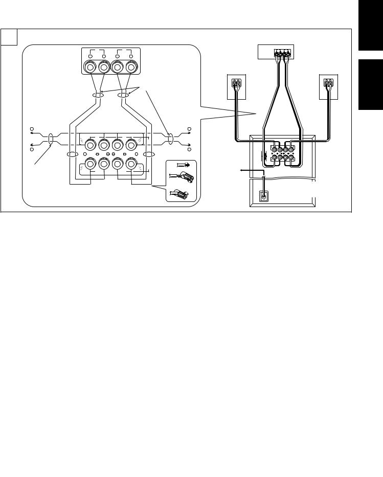
There are 2 speaker level connection methods:
Method 1 (ı)
Place the unit between the connection of the stereo amplifier’s or receiver’s speaker terminals and the left and right speakers.
1.Connect the unit’s SPEAKER LEVEL INPUT terminals and the SPEAKERS terminals on the stereo amplifier or receiver with the specially provided speaker cords or the stereo system’s speaker cords.
÷Make sure L (+), L (–), R (+), R (–) are correctly aligned.
2.Connect the unit’s SPEAKER LEVEL OUTPUT terminals and the left/right speaker system terminals with the specially provided speaker cords or the stereo system’s speakers cord.
÷Make sure L (+), L (–), R (+), R (–) are correctly aligned.
Il y a deux façon de procéder au raccordement de niveau hautparleur :
1ère méthode (ı)
Connecter le subwoofer entre les bornes de haut-parleur de l’ampli-tuner ou de l’amplificateur stéréo et les enceintes de droite et de gauche.
1.Relier les bornes d’entrée de niveau haut-parleur (SPEAKER LEVEL INPUT) du subwoofer et les bornes de haut-parleur de l’ampli-tuner ou de l’amplificateur stéréo à l’aide des câbles de haut-parleur fournis ou des câbles de haut-parleur de la chaîne stéréo.
÷S’assurer de bien faire correspondre L (+), L (–), R (+) et R (–).
2.Relier les bornes de sortie de niveau haut-parleur (SPEAKER LEVEL OUTPUT) du subwoofer aux bornes de l’enceinte droite/gauche à l’aide des câbles de haut-parleur fournis ou des câbles de haut-parleur de la chaîne stéréo.
÷S’assurer de bien faire correspondre L (+), L (–), R (+) et R (–).
POWER-CORD CAUTION
Handle the power cord by the plug. Do not pull out the plug by tugging the cord and never touch the power cord when your hands are wet as this could cause a short circuit or electric shock. Do not place the unit, a piece of furniture, etc., on the power cord, or pinch the cord. Never make a knot in the cord or tie it with other cords. The power cords should be routed such that they are not likely to be stepped on. A damaged power cord can cause a fire or give you an electrical shock. Check the power cord once in a while. When you find it damaged, ask your nearest PIONEER authorized service center or your dealer for a replacement.
REMARQUE IMPORTANTE SUR LE CABLE D’ALIMENTATION
Tenir le câble d’alimentation par la prise. Ne pas débrancher la prise en tirant sur le câble et ne pas toucher le câble avec les mains mouillées. Cela risque de provoquer un court-circuit ou un choc électrique. Ne pas poser l’appareil ou un meuble sur le câble. Ne pas pincer le câble. Ne pas faire de noeud avec le câble ou l’attacher à d’autres câbles. Les câbles d’alimentation doivent être posés de façon à ne pas être écrasés. Un câble abîmé peut provoquer un risque d’incendie ou un choc électrique. Vérifier le câble d’alimentation de temps en temps. Contacter le service après-vente PIONEER le plus proche ou le revendeur pour un remplacement.
9
Português Español Svenska Nederlands Italiano Deutsch Français English
En/Fr

CONNECTIONS |
|
RACCORDEMENTS |
C
Amplifier's or Receiver's SPEAKERS terminals |
|||||
Bornes HAUT-PARLEUR de l’ampli-tuner ou de |
|||||
l’amplificateur |
|
|
|
Connect speaker cords 2 at |
|
|
R |
|
L |
||
|
|
a time. |
|||
+ |
_ |
_ |
+ |
||
Raccorder les câbles de |
|||||
|
|
||||
|
|
|
|
haut-parleur deux par deux. |
|
+ |
|
|
|
+ To left speaker |
|
|
|
|
|
system |
|
|
|
|
|
A l’enceinte |
|
_ |
|
|
|
acoustique gauche |
|
|
|
|
_ |
||
To right speaker |
|
|
|
|
|
system |
|
|
|
Speaker cords |
|
A l’enceinte |
|
|
|
Câble de haut-parleur |
|
acoustique droite |
|
|
|
|
|
|
R |
|
L |
|
|
+ |
|
|
|
+ |
|
|
R |
|
L |
|
|
S-W110S-QL
S-W110S-K
S-W150S
Stereo amplifier or Receiver
Ampli-tuner ou amplificateur stéréo
RL
+_ _ +
Right Speaker system |
Left speaker system |
||
Enceinte acoustique |
Enceinte acoustique |
||
droite |
|
gauche |
|
_ |
+ |
_ |
+ |
|
|
||
S-W110S-QL
S-W110S-K
S-W150S
R |
L |
+ |
+ |
R |
L |
To AC |
|
|
socket |
|
|
A une |
|
|
prise |
Supplied AC power cord |
|
secteur |
||
Cordon d’alimentation fourni |
||
murale |
||
|
Method 2 (Ç)
Connect the unit to the stereo amplifier's or receiver's speaker terminals at the same time the left and right speakers are connected.
1.Fasten together the core of the speaker cord from the left/ right speaker system and one end of the speaker cord provided with the unit, and connect them to the speaker terminal on the stereo amplifier or receiver.
2.Connect the other end of the specially provided speaker cords to the SPEAKER LEVEL INPUT terminals on the unit.
÷Make sure L (+), L (–), R (+), R (–) are correctly aligned.
÷Do not use the unit’s SPEAKER LEVEL OUTPUT terminals.
NOTE:
÷If the stereo amplifier or receiver has 2 sets of speaker terminals (A, B) and these are connected to empty terminals on the unit and “A + B” is selected with the speaker switch, sound may not come out of the left/right speakers, depending on the stereo amplifier or receiver being used (a stereo amplifier or receiver is constructed so that, when “A + B” is selected with the speaker switch, A and B are in series connection).
2ème méthode (Ç)
Connecter le subwoofer aux bornes de haut-parleur de l’amplituner ou de l’amplificateur stéréo en même temps que l’enceinte droite/gauche.
1.Attacher ensemble la partie centrale du câble connecté à l’enceinte droite/gauche et une extrémité de chacun des câbles de haut-parleur fournis et les connecter aux bornes de haut-parleur de l’ampli-tuner ou de l’amplificateur stéréo.
2.Connecter l’autre extrémité des câbles de haut-parleur fournis aux bornes d’entrée de niveau haut-parleur (SPEAKER LEVEL INPUT) du subwoofer.
÷S’assurer de bien faire correspondre L (+), L (–), R (+) et R (–).
÷Ne pas utiliser la borne de sortie de niveau haut-parleur (SPEAKER LEVEL OUTPUT) du subwoofer.
REMARQUE:
÷Lorsque l’ampli-tuner ou l’amplificateur stéréo est pourvu de deux groupes de bornes de haut-parleur (A, B) et que celles ci sont connectées à des bornes vides du subwoofer, alors que le sélecteur de haut-parleur est réglé sur “A + B”, il est possible que l’enceinte droite et l’enceinte gauche ne produisent pas de son selon le modèle d’ampli-tuner ou amplificateur stéréo utilisé (à savoir un ampli-tuner ou amplificateur stéréo sur lequel A et B sont connectées en série lorsque le sélecteur de haut-parleur est réglé sur “A + B”).
10
En/Fr
OPERATION
For details regarding operating part functions, refer to page 6.
1. Turn the POWER switch 1 ON.
÷If the unit’s power cord is connected to a switched AC outlet on the stereo amplifier or receiver and the switch is left ON, the unit can be turned ON/OFF together with the stereo amplifier or receiver.
÷If the unit cannot be connected to the stereo amplifier or receiver, turn the power to the stereo amplifier or receiver ON before turning the power to the unit ON. When turning the power OFF, turn the power to the unit OFF before turning the power to the stereo amplifier or receiver OFF.
2.Operate the stereo amplifier or receiver and adjust the volume of the left/right speakers.
3.Adjust the strength of the bass with the LEVEL knob 4.
÷ When necessary, operate the TURNOVER knob 5 and PHASE switch 3, and then adjust with the LEVEL knob 4.
FONCTIONNEMENT
Se reporter à la page 6 pour plus de renseignements sur les fonctions des diverses bornes et commandes.
1. Mettre le subwoofer sous tension au moyen de l’interrupteur POWER 1.
÷Lorsque le cordon d’alimentation du subwoofer est branché à une prise d’alimentation CA commutée de l’ampli-tuner ou de l’amplificateur stéréo et que l’interrupteur est laissé à la position ON, il sera possible de mettre le subwoofer sous/ hors tension avec l’ensemble de la chaîne.
÷Pour couper l’alimentation, toujours mettre le subwoofer hors tension avant l’ampli-tuner ou l’amplificateur stéréo.
2.Faire fonctionner l’ampli-tuner ou amplificateur stéréo et régler le volume des enceintes de droite et de gauche.
3.Régler la puissance des graves à l’aide du bouton
LEVEL 4.
÷Lorsque nécessaire, utiliser le bouton de réglage TURNOVER 5 et le sélecteur PHASE 3 et régler ensuite le volume avec le bouton LEVEL 4.
11
En/Fr
Português Español Svenska Nederlands Italiano Deutsch Français English

TROUBLESHOOTING
Incorrect operations are often mistaken for trouble and malfunctions. If you think that there is something wrong with this component, check the points below. Sometimes the trouble may lie in another component. Investigate the other components and electrical appliances being used If the trouble cannot be rectified even after exercising the checks listed below, ask your nearest PIONEER authorized service center or your dealer to carry out repair work.
SYMPTOM |
|
CAUSE |
REMEDY |
|
|
|
|
1 No power is being supplied |
÷ Power supply plug is not correctly |
÷ Insert plug securely. |
|
(Indicator does not light up when |
|
inserted. |
|
power switch is turned on.) |
|
|
|
|
|
|
|
2 No sound |
÷ Connection of speaker or accessory RCA |
÷ Check again and connect correctly. |
|
(Indicator is lit.) |
|
plug cord is wrong or disconnected. |
÷ Turn clockwise slowly. |
|
÷ LEVEL knob is set to MIN. |
||
|
|
|
|
3 Sound is weak. |
÷ Polarity of the speaker cords (from the |
÷ Confirm the polarity of the wires and |
|
(LEVEL knob is turned up.) |
|
amplifier or receiver to this unit) is |
connect them correctly. |
|
|
reversed. |
|
|
|
|
|
4 Sound is distorted. |
÷ |
Level is too high. |
÷ Turn the LEVEL knob counter-clockwise to lower the |
|
|
|
level. |
|
÷ |
Input level is too high. |
÷ Turn the amplifier’s output level (volume, bass control, |
|
|
|
bass boost) counter-clockwise to lower the level. |
|
|
|
|
5 Howling noise occurs. |
÷ Power supply to amplifier or speaker |
÷ Connect power supply to amplifier and turn |
|
|
|
switch is turned off. |
speaker switch on. |
|
÷ Subwoofer level is set too high. |
÷ Place the subwoofer a good distance from |
|
|
|
|
speakers. Turn the LEVEL knob counter- |
|
|
|
clockwise to lower the volume. |
|
|
|
|
6 Much noise when listening to AM |
÷ The AM loop antenna or the FM indoor |
÷ Increase the distance between the AM or |
|
or FM broadcasts. |
|
antenna is close to this unit. |
FM antenna (for indoor use) and this unit. |
|
|
|
|
SPECIFICATIONS
Cabinet ......................................................... |
Floor type system |
|
Speaker (Magnetically shielded type) |
........... 22 cm cone type |
|
Power Amplifier Continuous Power Output (RMS) |
||
S-W110S-QL/S-W110S-K ............... |
110 W/4 Ω |
(30 – 200 Hz) |
S-W150S ......................................... |
150 W/4 Ω |
(30 – 200 Hz) |
÷ Above specifications are for when power supply is 230 V.
Input (sensitivity at 100 Hz/impedance) |
|
|
SPEAKER LEVEL .................................. |
2.0 V + 2.0 V/15 kΩ |
|
|
(both channels in-phase) |
|
LINE LEVEL (RCA jack) .................................... |
200 mV/50 kΩ |
|
Turnover Frequency .......... |
50 – 200 Hz (continuously variable) |
|
Outline Dimension |
|
|
S-W110S-QL/S-W110S-K .... |
250 (W) x 480 (H) x 475 (D) mm |
|
S-W150S ......................... |
280 (W) x 480 (H) x 495 (D) mm |
|
Weight (without package) |
|
|
S-W110S-QL/S-W110S-K ............................................ |
14.2 kg |
|
S-W150S ..................................................................... |
19.7 kg |
|
Power Requirements .......................... |
220 – 230 V~, 50/60 Hz |
|
Power Consumption |
|
|
S-W110S-QL/S-W110S-K ............................................. |
210 W |
|
S-W150S ....................................................................... |
300 W |
|
Accessories ............................................... |
Speaker cords |
x 2 |
|
RCA plug cord x 1 |
|
|
Operating instructions |
x 1 |
|
Warranty card |
x 1 |
NOTE:
Specifications and design subject to possible modification without notice, due to improvements.
Published by Pioneer Corporation.
Copyright © 2001 Pioneer Corporation.
All rights reserved.
12
En/Fr

DEPANNAGE
Il arrive souvent que des anomalies de fonctionnement ou des problèmes apparents soient dus à de simples erreurs de manipulation. Si cette enceinte semble ne pas fonctionner correctement, contrôler les points suivants. Parfois un autre élément de la chaîne est à l’origine du problème. Contrôler tous les éléments et accessoires électriques utilisés. Si l’origine du problème n’a pas pu être trouvée après avoir effectué les contrôles suivants, s’adresser au service après-vente PIONEER le plus proche ou à un distributeur.
SYMPTÔME |
|
CAUSE |
|
|
REMÈDE |
|
|
|
|
|
|
|
|
|
|
1 L’enceinte ne se met pas sous tension (le |
÷ |
Le cordon d’alimentation n’est pas branché |
÷ |
Brancher |
correctement |
le |
cordon |
témoin d’alimentation ne s’allume pas |
|
correctement. |
|
d’alimentation. |
|
|
|
lorsque l’interrupteur POWER est enfoncé). |
|
|
|
|
|
|
|
|
|
|
|
||||
2 Pas de son |
÷ |
Le câble de haut-parleur ou le câble à prise |
÷ Tourner lentement ce bouton dans le sens des |
||||
(Le témoin d’alimentation s’allume.) |
|
RCA est déconnecté ou mal connecté. |
|
aiguilles d’une montre. |
|
|
|
|
÷ Le bouton de réglage du volume LEVEL est |
÷ Vérifier les raccordements et connecter |
|||||
|
|
réglé sur MIN. |
|
correctement. |
|
|
|
|
|
|
|
|
|
|
|
3 Le son est faible |
÷ |
La polarité des câbles de haut-parleur (entre |
÷ Confirmer |
la polarité des |
câbles |
et les |
|
(Le bouton de réglage du volume |
|
l’ampli-tuner ou amplificateur et cette |
|
reconnecter correctement. |
|
|
|
LEVEL est correctement réglé.) |
|
enceinte) a été inversée. |
|
|
|
|
|
|
|
|
|
||||
4 Le son est déformé. |
÷ |
Le niveau est trop élevé. |
÷ Tourner le bouton de réglage du volume LEVEL |
||||
|
|
|
|
dans le sens contraire des aiguilles d’une montre |
|||
|
|
|
|
pour baisser le niveau. |
|
|
|
|
÷ Le niveau d’entrée est trop élevé. |
÷ Utiliser les commandes de réglage du niveau de |
|||||
|
|
|
|
sortie (volume, réglage grave, renforcement des |
|||
|
|
|
|
basses) de l’amplificateur pour baisser le niveau. |
|||
|
|
|
|
|
|||
5 Un bruit de cornemuse se produit. |
÷ |
L’amplificateur n’est pas sous tension ou le |
÷ |
Mettre l’amplificateur sous tension et mettre le |
|||
|
|
sélecteur de haut-parleur est mis sur OFF. |
|
sélecteur de haut-parleur sur ON. |
|
||
|
÷ |
Le niveau du subwoofer est trop élevé. |
÷ |
Placer le subwoofer à une bonne distance des |
|||
|
|
|
|
autres enceintes. Tourner le bouton de réglage du |
|||
|
|
|
|
volume LEVEL dans le sens contraire des aiguilles |
|||
|
|
|
|
d’une montre pour baisser le niveau. |
|
||
|
|
|
|
||||
6 Nombreux parasites lors d’écoute |
÷ |
L’antenne-cadre AM ou l’antenne intérieure |
÷ Augmenter la distance entre l’antenne AM ou |
||||
d’émission AM ou FM. |
|
FM est proche de cette unité. |
|
FM (pour usage intérieur) et cette unité. |
|||
|
|
|
|
|
|
|
|
FICHE TECHNIQUE
Coffret ............................................ |
Système à poser sur le sol |
Haut-parleur (à écran magnétique) ........... |
Type conique 22 cm |
Amplificateur de puissance Puissance de sortie continue (RMS)
S-W110S-QL/S-W110S-K ............... |
110 W/4 Ω |
(30 – 200 Hz) |
S-W150S ......................................... |
150 W/4 Ω |
(30 – 200 Hz) |
÷Les spécifications ci-dessus s’appliquent lorsque la tension d’alimentation est de 230 V.
Entrée (sensibilité à 100 Hz/impédance)
SPEAKER LEVEL .................................... |
2,0 V + 2,0 V/15 kΩ |
|
(les deux voies en phase) |
LINE LEVEL (prise RCA) .................................. |
200 mV/50 kΩ |
Fréquence de transition ....... |
50 – 200 Hz (réglable en continu) |
Dimensions externes |
|
S-W110S-QL/S-W110S-K ...... |
250 (L) x 480 (H) x 475 (P) mm |
S-W150S .............................. |
280 (L) x 480 (H) x 495 (P) mm |
Poids (sans emballage) |
|
S-W110S-QL/S-W110S-K ............................................. |
14,2 kg |
S-W150S ..................................................................... |
19,7 kg |
Alimentation électrique ........... |
220 – 230 Volts CA , 50/60 Hz |
Consommation d’énergie |
|
S-W110S-QL/S-W110S-K ............................................. |
210 W |
S-W150S ....................................................................... |
300 W |
Accessoires fournis ..................... |
Câbles pour haut-parleur x 2 |
|
Câble à prise RCA x 1 |
|
Mode d’emploi x 1 |
|
Fiche de garantie x 1 |
REMARQUE :
Les caractéristiques techniques et le design peuvent être modifiés sans aucun avis pour y apporter des améliorations.
Publication de Pioneer Corporation. © 2001 Pioneer Corporation.
Tous droits de reproduction et de traduction réservés.
13
Português Español Svenska Nederlands Italiano Deutsch Français English
En/Fr

Wir danken Ihnen für den Kauf dieses Pioneer-Produkts. Lesen Sie sich bitte diese Bedienungsanleitung durch. Dann wissen Sie, wie Sie Ihr Gerät richtig bedienen. Bewahren Sie sie an einem sicheren Platz auf, um auch zukünftig nachschlagen zu können.
In manchen Ländern oder Verkaufsgebieten weichen die Ausführungen von Netzstecker oder Netzsteckdosen u.U. von den in den Abbildungen gezeigten ab; die Anschlußund Bedienungsverfahren des Gerätes sind jedoch gleich.
Grazie per aver acquistato questo prodotto Pioneer.
Leggere attentamente questo manuale di istruzioni per familiarizzarsi con l’uso dell’apparecchio. Conservare poi il manuale per ogni eventuale futuro riferimento.
I modelli disponibili in alcuni paesi o regioni possono avere la forma della spina del cavo d’alimentazione e della presa ausiliaria di corrente diversa da quella mostrata nelle illustrazioni, ma il loro modo di collegamento e funzionamento è lo stesso.
14
Ge/It

ZUBEHÖR / ACCESSORI IN DOTAZIONE
÷ Lautsprecherkabel x 2 |
÷ Cinchsteckerkabel x 1 |
÷ Bedienungsanleitung x 1 |
÷ Garantiekarte x 1 |
÷ Cavi altoparlante x 2 |
÷ Cavo con spinotti RCA x 1 |
÷ Istruzioni per l'uso x 1 |
÷ Garanzia x 1 |
MERKMALE |
|
CARATTERISTICHE PECULIARI |
|
|
|
7110 W (S-W110S-QL, S-W110S-K), 150W (S-W150S) Leistung für Video-Wiedergabe wie Dolby* Digital mit einem großen Dynamikumfang.
7Ausgestattet mit 22cm-System.
7Übergangsfrequenz kann kontinuierlich sein (50 – 200 Hz).
7Schalter für Phasenumkehrung (0˚/180˚).
72 Systeme, bestehend aus einem Eingang, der mit den Verstärker-Lautsprecherklemmen verbunden wird, und einem Eingang, der mit der SUBWOOFER PRE-OUT-Klemme verbunden wird.
*In Lizenz von Dolby Laboratories hergestellt. “Dolby” und das Doppel-D-symbol sind Warenzeichen der Dolby Laboratories. Vertrauliche, unveröffentlichte Schriften. © 1992-1997 Dolby Laboratories. Alle Rechte vorbehalten.
IN KOMBINATION MIT LAUTSPRECHERN
Nachstehend sind die Frequenzeigenschaften des S- W110S-QL/S-W110S-K/S-W150S in Kombination mit kleinen Lautsprechern dargestellt. Wie aus der Abbildung hervorgeht, wird der tiefe Frequenzbereich verbessert.
÷Diese Eigenschaften wurden in einem echofreien Raum erhalten. Die Wirkung eines zusätzlichen S-W110S-QL/S- W110S-K/S-W150S in einem normalen Hörraum ist bei richtiger Anordnung größer als in der Darstellung.
kleiner Lautsprecher + S-W110S-QL/S-W110S-K/S-W150S
(dB) |
|
ANSPRECHEN |
kleiner Lautsprecher |
|
FREQUENZ (Hz)
÷Für die Wiedergabe von Dolby* Digital wird empfohlen, einen besonderen Kanal für den Subwoofer vorzusehen. Der S-W110S-QL/S-W110S-K/S-W150S ist besonders effektiv für die Wiedergabe von LFE (Low Frequency Effect: Klangeffekte wie Rumpeln der Erde, die den Bildeindruck verstärken sollen).
Dolby* Digital
Dolby Digital ist die Bezeichnung des Dolby Surround Mehrkanal-Digitalsystems, das als Weiterführung des Dolby Pro-Logic Surround von Dolby Surround entwickelt wurde. Dolby Digital wird auch als 5.1-Kanal-System bezeichnet, weil es über 5 Kanäle im Frequenzbereich von 20 Hz bis 20 kHz (vorne links und rechts, Mitte und hinten links und rechts) und einen unabhängigen Kanal für den Subwoofer verfügt. Der Subwooferkanal wird auch LFE-Kanal (Low Frequency Effect) genannt. Der LFE-Kanal wird nach individuellem Geschmack zur Verstärkung der Baßwirkung eingesetzt.
7110 W (S-W110S-QL, S-W110S-K), 150W (S-W150S) di potenza al servizio della riproduzione di prodotti d'impiego audiovisivo quali il Dolby* Digital con un ampio range dinamico.
7Provvisto di driver da 22 cm.
7Possibilità di frequenza di transizione continua (50 – 200 Hz).
7Comando di conversione di fase (0˚/180˚).
72 sistemi comprendenti un ingresso che va ai terminali altoparlante dell'amplificatore e un ingresso che va al terminale Pre-uscita subwoofer (SUBWOOFER PRE-OUT).
*Prodotto sotto licenza della Dolby Laboratories. “Dolby” ed il simbolo doppia D sono marchi registrati della Dolby Laboratories. Lavori non pubblicati riservati. © 1992-1997 Dolby Laboratories. Tutti i diritti sono riservati.
IN COMBINAZIONE CON ALTOPARLANTI
Sotto vengono mostrate le curve di frequenza di S-W110S- QL/S-W110S-K/S-W150S combinato con altoparlanti di piccole dimensioni. Come appare in queste figure, il range delle basse frequenze è aumentato.
÷Queste curve speciali vengono ottenute in una camera insonorizzata. Se adeguatamente posizionato in un normale ambiente di ascolto la curva d'effetto di un S- W110S-QL/S-W110S-K/S-W150S addizionale è miglire di quella mostrata.
Altoparlante di piccole dimensioni + S-W110S-QL/S-W110S-K/S-W150S
(dB) |
|
RISPOSTA |
Altoparlante di piccole dimensioni |
|
FREQUENZA (Hz)
÷Con la riproduzione di Dolby* Digital viene fortemente raccomandato l'instaurazione di un canale speciale per il subwoofer; e con la riproduzione di LFE (Effetto alle basse frequenze: effetto acustico quale il rombo di bassa frequenza della terra, il cui scopo è intensificare l'intensità video), S- W110S-QL/S-W110S-K/S-W150S è particolarmente efficace.
Dolby* Digital
Dolby Digital è il nome del sistema digitale multicanali Dolby Surround sviluppato da Dolby Surround come continuazione di Dolby Pro Logic Surround.
Dolby Digital viene anche detto sistema a 5.1 canali. Questo in quanto è dotato di 5 canali nel range di frequenze che vanno da 20 Hz a 20 kHz (anteriore sinistro e destro, centrale, e posteriore sinistro e destro) e di un canale indipendente per il subwoofer. Il canale subwoofer viene anche detto LFE (Effetto alle basse frequenze).
L'utilizzo del canale LFE avviene in base a scelte individuali in modo da aumentare l'effetto alle basse frequenze.
15
Português Español Svenska Nederlands Italiano Deutsch Français English
Ge/It
AUFSTELLUNG |
|
INSTALLAZIONE |
|
A |
|
B |
2 |
|
|
||
1 |
2 |
1 |
3 |
|
|
4 |
|
3 |
|
|
5 |
|
|
|
|
4 |
|
6 |
7 |
|
|
||
Aufstellen der Lautsprecher
Der Subwoofer reproduziert die tiefen Frequenzen in Mono, wobei ausgenutzt wird, daß das menschliche Gehör tiefe Töne nicht mehr räumlich einordnen kann. Da das Richtungsgefühl keine Rolle spielt, kann der Subwoofer fast überall angeordnet werden. Wenn er jedoch zu weit entfernt ist, kann der Ton vom linken und rechten Lautsprecher unnatürlich klingen.
÷Kriterien für die Anordnung des Subwoofers (Å)
1 linker Lautsprecher
2 rechter Lautsprecher
3 empfohlener Aufstellbereich für Subwoofer
4 Hörposition
÷Beispiel der Lautsprecheranordnung (ı)
1 vorderer linker Lautsprecher
2 Mittenlautsprecher
3 vorderer rechter Lautsprecher
4 Subwoofer
5 Hörbereich
6 hinterer linker Lautsprecher
7 hinterer rechter Lautsprecher
HINWEISE:
÷Um das Bild eines in der Nähe befindlichen Fernsehgeräts nicht zu stören, sollten magnetisch abgeschirmte Lautsprecher verwendet werden. Dies gilt insbesondere für den Mittenlautsprecher, weil dieser sich gewöhnlich nahe am Fernsehgerät befindet.
÷Die Lautsprecher für den linken und rechten Kanal sollten in gleichen Abständen vom Fernsehgerät und etwa 1,8 m voneinander aufgestellt werden.
÷Den mittleren Lautsprecher auf oder unter dem Fernseher aufstellen, damit der Ton des mittleren Kanals mit dem Fernsehschirm übereinstimmt.
÷Die hinter en Lautsprecher (Surroundlautsprecher) wirken am besten, wenn sie direkt an den Seiten des Hörers oder geringfügig nach hinten versetzt angeordnet werden, dabei sollten sie sich etwa 1 Meter höher als die Ohren des Hörers befinden.
Insrallazione dell altoparlante
Il subwoofer riproduce i toni bassi in monoaurale avvalendosi del fatto che l'orecchio umano perde il senso della direzione nel caso dei suoni di bassa tonalità. Siccome il senso della direzione viene perso, il subwoofer può essere installato quasi dappertutto. Tuttavia, in caso di installazione in un posto troppo lontano, il suono dagli altoparlanti sinistro e destro potrebbe diventare non naturale.
÷Criteri di installazione del subwoofer (Å)
1 Altoparlante sinistro
2 Altoparlante destro
3 Range di installazione raccomandato per il subwoofer
4 Posizione di ascolto
÷Un esempio di posizionamento degli altoparlanti (ı
1 Altoparlante anteriore sinistro
2 Altoparlante centrale
3 Altoparlante anteriore destro
4 Subwoofer
5 Area di ascolto
6 Altoparlante posteriore sinistro
7 Altoparlante posteriore destro
NOTA:
÷Per evitare interferenze che disturbino le immagini di un apparecchio
TV vicino, usare sistemi altoparlanti magneticamente schermati. Questo si rivela particolarmente importante nel caso dell'altoparlante centrale in quanto solitamente viene a trovarsi vicino all'apparecchio TV.
÷Posizionare gli altoparlanti dei canali destro e sinistro ad eguale distanza dall'ap parecchio TV e a circa 1,8 metri uno dall'altro.
÷Installare l‘altoparlante centrale sopra o sotto la TV, in modo che il suono del canale centrale sia localizzato sullo schermo della TV.
÷Gli altoparlanti (surround) posteriori risultano più efficaci quando vengo installati parallelamente direttamente di fianco, o leggermente dietro, alla persona che ascolta, e ad un livello di circa 1 metro più alti delle orecchie.
ACHTUNG:
Achten Sie darauf, den Lautsprecher beim Aufstellen auf dem Fernseher mit einem Klebeband oder auf eine andere geeignete Art und Weise zu sichern.
Anderenfalls kann der Lautsprecher infolge von äußeren Erschütterungen, wie z.B. einem Erdbeben, vom Fernsehgerät herunterfallen, wodurch in der Nähe befindliche Personen zu Schaden kommen könnten oder der Lautsprecher beschädigt werden könnte.
16
Ge/It
ATTENZIONE:
Quando si installa l‘altoparlante centrale sopra la TV fermarlo con del nastro adesivo o altri mezzi idonei.
In caso contrario l‘altoparlante potrebbe cadere dalla TV a seguito di urti esterni, ad esempio durante un terremoto, mettendo in pericolo chi si trova nelle vicinanze o danneggiandosi.
 Loading...