


 Loading...
ORDER NO.
CRT4642
DEH-6310SD/XSUR
CD RDS RECEIVER
DEH-6310SD/XSUR
DEH-6300UB/XSUC
DEH-63UB/XSUC
This service manual should be used together with the following manual(s):
Model No. |
Order No. |
Mech. Module |
|
|
|
Remarks |
|||||||||
|
|
|
|
|
|
|
|
|
|
|
|
|
|
|
|
CX-3269 |
CRT4488 |
S11.1STD-DOUT |
CD Mech. Module : Circuit Descriptions, Mech. Descriptions, Disassembly |
||||||||||||
|
|
|
|
|
|
|
|
|
|
|
|
|
|
|
|
|
|
|
|
|
|
|
|
|
|
|
|
|
|
|
|
|
|
|
|
|
|
|
|
|
|
|
|
|
|
|
|
|
|
|
|
|
|
|
|
|
|
|
|
|
|
|
|
|
|
|
|
|
|
|
|
|
|
|
|
|
|
|
|
|
|
|
|
|
|
|
|
|
|
|
|
|
|
|
|
For details, refer to "Important Check Points for Good Servicing".
PIONEER CORPORATION 1-1, Shin-ogura, Saiwai-ku, Kawasaki-shi, Kanagawa 212-0031, Japan PIONEER ELECTRONICS (USA) INC. P.O. Box 1760, Long Beach, CA 90801-1760, U.S.A.
PIONEER EUROPE NV Haven 1087, Keetberglaan 1, 9120 Melsele, Belgium
PIONEER ELECTRONICS ASIACENTRE PTE. LTD. 253 Alexandra Road, #04-01, Singapore 159936
 PIONEER CORPORATION 2010
K-ZZZ NOV. 2010 Printed in Japan
|
1 |
|
2 |
|
3 |
|
4 |
|
SAFETY INFORMATION
A |
CAUTION |
|
This service manual is intended for qualified service technicians; it is not meant for the casual do-it-yourselfer. |
|
Qualified technicians have the necessary test equipment and tools, and have been trained to properly and safely repair |
|
complex products such as those covered by this manual. |
|
Improperly performed repairs can adversely affect the safety and reliability of the product and may void the warranty. |
|
If you are not qualified to perform the repair of this product properly and safely, you should not risk trying to do so |
|
and refer the repair to a qualified service technician. |
|
|
|
WARNING |
|
This product may contain a chemical known to the State of California to cause cancer, or birth defects or |
|
other reproductive harm. |
B |
Health & Safety Code Section 25249.6 - Proposition 65 |
|
|
|
Where in a manufacturer’s service documentation, for example in circuit diagrams or lists |
|
of components, a symbol is used to indicate that a specific component shall be replaced only |
|
by the component specified in that documentation for safety reasons, the following symbol shall |
|
be used: |
|
|
|
|
-Safety Precautions for those who Service this Unit.
When checking or adjusting the emitting power of the laser diode exercise caution in order to get safe, reliable results.
C
Caution:
1.During repair or tests, minimum distance of 13 cm from the focus lens must be kept.
2.During repair or tests, do not view laser beam for 10 seconds or longer.
CAUTION:
USE OF CONTROLS OR ADJUSTMENTS OR PERFORMANCE OF PROCEDURES OTHERTHANTHOSE SPECIFIED HEREIN MAY RESULT IN HAZARDOUS RADIATION EXPOSURE.
CAUTION
DThis product is a class 1 laser product classified under the Safety of laser products, IEC
60825-1:2007, and contains a class 1M laser module. To ensure continued safety, do not re-
move any covers or attempt to gain access to the inside of the product. Refer all servicing to qualified personnel.
|
|
|
|
CAUTION—CLASS 1M INVISIBLE LASER |
|
E |
RADIATION WHEN OPEN, DO NOT VIEW |
|
DIRECTLY WITH OPTICAL INSTRUMENTS. |
||
|
WARNING!
The AEL (accessible emission level )of the laser power output is less than CLASS 1 but the laser component is capable of emitting radiation exceeding the limit for CLASS 1.
A specially instructed person should do servicing operation of the apparatus.
F
2 |
DEH-6310SD/XSUR |
|
1 |
|
2 |
|
3 |
|
4 |
|
|
|
|
|
|
|
5 |
|
6 |
|
7 |
|
8 |
Laser diode characteristics
Wave length : 785 nm to 814 nm
Maximum output : 1 190 µW(Emitting period : unlimited)
Additional Laser Caution
Transistors Q101 in PCB drive the laser diodes.
When Q101 is shorted between their terminals, the laser diodes will radiate beam. If the top cover is removed with no disc loaded while such short-circuit is continued, the naked eyes may be exposed to the laser beam.
A
B
CAUTION
Danger of explosion if battery is incorrectly replaced.
Replaced only with the same or equivalent type recommended by the manufacture.
Discord used batteries according to the manufacture's instructions.
C
D
E
F
|
|
|
|
DEH-6310SD/XSUR |
|
|
|
3 |
|
||
|
5 |
|
6 |
|
|
7 |
|
8 |
|
|
|
|
|
|
|
|
|
||||||
|
1 |
|
2 |
|
3 |
|
4 |
|
[Important Check Points for Good Servicing]
AIn this manual, procedures that must be performed during repairs are marked with the below symbol. Please be sure to confirm and follow these procedures.
1.Product safety
Please conform to product regulations (such as safety and radiation regulations), and maintain a safe servicing environment by following the safety instructions described in this manual.
1 Use specified parts for repair.
Use genuine parts. Be sure to use important parts for safety.
2 Do not perform modifications without proper instructions.
Please follow the specified safety methods when modification(addition/change of parts) is required due to interferences such as
Bradio/TV interference and foreign noise.
3 Make sure the soldering of repaired locations is properly performed.
When you solder while repairing, please be sure that there are no cold solder and other debris. Soldering should be finished with the proper quantity. (Refer to the example)
4 Make sure the screws are tightly fastened.
Please be sure that all screws are fastened, and that there are no loose screws.
5 Make sure each connectors are correctly inserted.
Please be sure that all connectors are inserted, and that there are no imperfect insertion.
6 Make sure the wiring cables are set to their original state.
C
Please replace the wiring and cables to the original state after repairs. In addition, be sure that there are no pinched wires, etc.
7 Make sure screws and soldering scraps do not remain inside the product.
Please check that neither solder debris nor screws remain inside the product.
8 There should be no semi-broken wires, scratches, melting, etc. on the coating of the power cord.
Damaged power cords may lead to fire accidents, so please be sure that there are no damages.
If you find a damaged power cord, please exchange it with a suitable one.
9 There should be no spark traces or similar marks on the power plug.
When spark traces or similar marks are found on the power supply plug, please check the connection and advise on secure
Dconnections and suitable usage. Please exchange the power cord if necessary. a Safe environment should be secured during servicing.
When you perform repairs, please pay attention to static electricity, furniture, household articles, etc. in order to prevent injuries. Please pay attention to your surroundings and repair safely.
2. Adjustments
 To keep the original performance of the products, optimum adjustments and confirmation of characteristics within specification. Adjustments should be performed in accordance with the procedures/instructions described in this manual.
3. Lubricants, Glues, and Replacement parts |
E |
Use grease and adhesives that are equal to the specified substance. |
Make sure the proper amount is applied. |
4. Cleaning |
For parts that require cleaning, such as optical pickups, tape deck heads, lenses and mirrors used in projection monitors, proper cleaning should be performed to restore their performances.
5. Shipping mode and Shipping screws
To protect products from damages or failures during transit, the shipping mode should be set or the shipping screws should be
installed before shipment. Please be sure to follow this method especially if it is specified in this manual.
F
4 |
DEH-6310SD/XSUR |
|
1 |
|
2 |
|
3 |
|
4 |
|
|
|
|
|
|

|
5 |
|
|
6 |
|
|
7 |
|
8 |
|
CONTENTS |
|
|
|
|
|
|
||
|
SAFETY INFORMATION ..................................................................................................................................... |
|
|
|
|
2 |
|||
|
1. SERVICE PRECAUTIONS................................................................................................................................ |
|
|
|
|
6 |
|||
|
1.1 SERVICE PRECAUTIONS ......................................................................................................................... |
|
|
|
|
6 |
|||
|
1.2 NOTES ON SOLDERING........................................................................................................................... |
|
|
|
|
7 |
|||
|
2. SPECIFICATIONS............................................................................................................................................. |
|
|
|
|
8 |
|||
|
2.1 SPECIFICATIONS ...................................................................................................................................... |
|
|
|
|
8 |
|||
|
2.2 DISC/CONTENT FORMAT ....................................................................................................................... |
|
|
|
|
10 |
|||
|
2.3 PANEL FACILITIES................................................................................................................................... |
|
|
|
|
11 |
|||
|
2.4 CONNECTION DIAGRAM........................................................................................................................ |
|
|
|
|
14 |
|||
|
3. BASIC ITEMS FOR SERVICE ........................................................................................................................ |
|
|
|
|
17 |
|||
|
3.1 CHECK POINTS AFTER SERVICING ..................................................................................................... |
|
|
|
|
17 |
|||
|
3.2 PCB LOCATIONS ..................................................................................................................................... |
|
|
|
|
17 |
|||
|
3.3 JIGS LIST ................................................................................................................................................. |
|
|
|
|
18 |
|||
|
3.4 CLEANING ............................................................................................................................................... |
|
|
|
|
18 |
|||
|
4. BLOCK DIAGRAM .......................................................................................................................................... |
|
|
|
|
20 |
|||
|
4.1 BLOCK DIAGRAM.................................................................................................................................... |
|
|
|
|
20 |
|||
|
5. DIAGNOSIS .................................................................................................................................................... |
|
|
|
|
23 |
|||
|
5.1 OPERATIONAL FLOWCHART ................................................................................................................. |
|
|
|
|
23 |
|||
|
5.2 ERROR CODE LIST................................................................................................................................. |
|
|
|
|
24 |
|||
|
5.3 CONNECTOR FUNCTION DESCRIPTION ............................................................................................. |
|
29 |
||||||
|
6. SERVICE MODE............................................................................................................................................. |
|
|
|
|
30 |
|||
|
6.1 DISPLAY TEST MODE............................................................................................................................. |
|
|
|
|
30 |
|||
|
6.2 CD TEST MODE....................................................................................................................................... |
|
|
|
|
31 |
|||
|
7. DISASSEMBLY ............................................................................................................................................... |
|
|
|
|
32 |
|||
|
8. EACH SETTING AND ADJUSTMENT ............................................................................................................ |
|
|
|
|
38 |
|||
|
8.1 CD ADJUSTMENT ................................................................................................................................... |
|
|
|
|
38 |
|||
|
8.2 CHECKING THE GRATING AFTER CHANGING THE PICKUP UNIT |
.................................................... |
39 |
||||||
|
8.3 PCL OUTPUT CONFIRMATION............................................................................................................... |
|
|
|
|
41 |
|||
|
9. EXPLODED VIEWS AND PARTS LIST .......................................................................................................... |
|
|
|
|
42 |
|||
|
9.1 PACKING .................................................................................................................................................. |
|
|
|
|
42 |
|||
|
9.2 EXTERIOR ............................................................................................................................................... |
|
|
|
|
44 |
|||
|
9.3 CD MECHANISM MODULE ..................................................................................................................... |
|
|
|
|
46 |
|||
|
10. SCHEMATIC DIAGRAM................................................................................................................................ |
|
|
|
|
48 |
|||
|
10.1 TUNER AMP UNIT (1/2) (GUIDE PAGE) ............................................................................................... |
|
48 |
||||||
|
10.2 TUNER AMP UNIT (2/2) (GUIDE PAGE) ............................................................................................... |
|
54 |
||||||
|
10.3 KEYBOARD UNIT .................................................................................................................................. |
|
|
|
|
60 |
|||
|
10.4 CD CORE UNIT (S11.1STD-DOUT) ...................................................................................................... |
|
|
|
|
62 |
|||
|
10.5 SD UNIT ................................................................................................................................................. |
|
|
|
|
64 |
|||
|
10.6 WAVEFORMS......................................................................................................................................... |
|
|
|
|
65 |
|||
|
11. PCB CONNECTION DIAGRAM .................................................................................................................... |
|
|
|
|
68 |
|||
|
11.1 TUNER AMP UNIT ................................................................................................................................. |
|
|
|
|
68 |
|||
|
11.2 KEYBOARD UNIT .................................................................................................................................. |
|
|
|
|
72 |
|||
|
11.3 CD CORE UNIT (S11.1STD-DOUT) ...................................................................................................... |
|
|
|
|
74 |
|||
|
11.4 SD UNIT ................................................................................................................................................. |
|
|
|
|
76 |
|||
|
12. ELECTRICAL PARTS LIST ........................................................................................................................... |
|
|
|
|
77 |
|||
A
B
C
D
E
F
|
|
|
|
DEH-6310SD/XSUR |
|
|
|
5 |
|
||
|
5 |
|
6 |
|
|
7 |
|
8 |
|
|
|
|
|
|
|
|
|
||||||

|
1 |
|
2 |
|
3 |
|
4 |
|
1. SERVICE PRECAUTIONS
1.1 SERVICE PRECAUTIONS
A
1.You should conform to the regulations governing the product (safety, radio and noise, and other regulations), and should keep the safety during servicing by following the safety instructions described in this manual.
2.Before disassembling the unit, be sure to turn off the power. Unplugging and plugging the connectors
during power-on mode may damage the ICs inside the unit.
3.To protect the pickup unit from electrostatic discharge during servicing, take an appropriate treatment (shorting-solder) by referring to "the DISASSEMBLY".
4.After replacing the pickup unit, be sure to check the grating.
5.Be careful in handling ICs. Some ICs such as MOS type are so fragile that they can be damaged by electrostatic induction.
B
6.  area and a heat sink becomes hot areas. Be careful not to burn yourself.
C
D
7.Notes on replacing parts
The part listed below is difficult to replace as a discrete component part.
|
|
ASSY NAME |
Ref No. |
Part No. |
Remarks |
|
|
|
|
|
|
|
|
Tuner Amp Unit |
IC601 |
PEG640A8 |
Narrow Pitch |
|
|||||
|
|
|
IC401 |
TDA7706 |
Narrow Pitch |
|
|
|
|||
|
|
|
IC501 |
R5S7262ZD144FPU |
Narrow Pitch |
|
|
|
IC571 |
CWW2867 |
Narrow Pitch |
|
|
|
|
|
|
8. How to Handle Infrared Deteching unit for Remote Control of Grille
EThe infrared deteching unit for remote control of keyboard unit is not fixed with cushion, etc.
When external force is applied on the infrared deteching unit for remote control, the light receiving sensitivity might be deteriorated since the lead bents and attaching angle of the light receiving part may be varied.
Please do not apply external force onto the infrared deteching unit for remote control. If any external force is applied by mistake, please confirm whether lead bending may exist or not.
If the lead is bent, please correct the angle between the lead and the light receiving part to be 90 degrees or replace the infrared deteching unit for remote control (GP1UXC14RK).
F
6 |
DEH-6310SD/XSUR |
|
1 |
|
2 |
|
3 |
|
4 |
|
|
|
|
|
|

5  6
6  7
7  8
8
9. Capacitor Bond Lock
Acetate Tape (GYH1026) |
|
|
1 Please stick acetate tape along white line. |
||
|
A |
|
2 Please confirm line hiding with acetate tape. |
||
* length of tape : 24 ± 4 mm |
|
|
1 |
2 |
|
|
|
|
|
|
|
B
1.2 NOTES ON SOLDERING
 For environmental protection, lead-free solder is used on the printed circuit boards mounted in this unit.
Be sure to use lead-free solder and a soldering iron that can meet specifications for use with lead-free solders for repairs accompanied by reworking of soldering.
 Compared with conventional eutectic solders, lead-free solders have higher melting points, by approximately 40
 C. Therefore, for lead-free soldering, the tip temperature of a soldering iron must be set to around 373
  C in general, although the temperature depends on the heat capacity of the PC board on which reworking is required and the weight of the tip of the soldering iron.
Compared with eutectic solders, lead-free solders have higher bond strengths but slower wetting times and higher melting temperatures (hard to melt/easy to harden).
The following lead-free solders are available as service parts:
 Parts numbers of lead-free solder:
GYP1006 1.0 in dia.
GYP1007 0.6 in dia.
GYP1008 0.3 in dia.
|
|
|
|
DEH-6310SD/XSUR |
|
|
|
7 |
||
|
5 |
|
6 |
|
|
7 |
|
8 |
|
|
|
|
|
|
|
||||||
C
D
E
F

|
|
1 |
|
|
2 |
|
|
|
2. SPECIFICATIONS |
||||
|
|
2.1 SPECIFICATIONS |
||||
A |
|
|
|
|
||
|
|
• DEH-63UB/XSUC, DEH-6300UB/XSUC |
||||
|
|
General |
|
|
|
|
|
|
Power source .................. |
14.4 V DC (10.8 V to 15.1 V al- |
|||
|
|
|
lowable) |
|||
|
|
Grounding system ............ |
Negative type |
|||
|
|
Maximum current consumption |
||||
|
|
|||||
|
|
................................. |
10.0 A |
|||
|
|
Backup current ................. |
5.0 mA or less |
|||
|
|
Dimensions (W × H × D): |
|
|
|
|
|
|
DIN |
|
|
|
|
|
|
Chassis .............. |
|
178 mm × 50 mm × 165 |
||
|
|
|
mm |
|||
B |
|
(7 in. × 2 in. × 6-1/2 in.) |
||||
Nose |
|
188 mm × 58 mm × 18 |
||||
|
|
|
||||
|
|
|
mm |
|||
|
|
|
(7-3/8 in.× 2-1/4 in.× 3/4 in.) |
|||
|
|
D |
|
|
|
|
|
|
Chassis .............. |
|
178 mm × 50 mm × 165 |
||
|
|
|
mm |
|||
|
|
|
(7 in.× 2 in.× 6-1/2 in.) |
|||
|
|
|
||||
|
|
Nose |
|
170 mm × 46 mm × 18 |
||
|
|
|
||||
|
|
|
mm |
|||
|
|
|
(6-3/4 in.× 1-3/4 in.× 3/4 in.) |
|||
|
|
Weight ........................... |
1.16 kg (2.6 lbs) |
|||
C |
Audio |
|
|
|
||
Maximum power output |
50 W × 4 |
|||||
|
|
|||||
|
|
|
70 W × 1/2 Ω (for subwoofer) |
|||
|
|
Continuous power output |
|
|
|
|
|
|
................................. |
22 W × 4 (50 Hz to 15 000 Hz, |
|||
|
|
|
5 % THD, 4 Ω load, both chan- |
|||
|
|
|
nels driven) |
|||
|
|
Load impedance .............. |
4 Ω (4 Ω to 8 Ω allowable) |
|||
|
|
Preout maximum output level |
||||
|
|
|||||
|
|
.................................. |
2.2 V |
|||
|
|
Equalizer (5-Band Graphic Equalizer): |
||||
|
|
Frequency ................. |
100/315/1.25k/3.15k/8k Hz |
|||
|
|
Gain ........................ |
±12 dB |
|||
|
|
HPF: |
|
|
|
|
D |
Frequency ................ |
50/63/80/100/125 Hz |
||||
Slope |
–12 dB/oct |
|||||
|
|
|||||
|
|
Subwoofer (mono): |
|
|
|
|
|
|
Frequency ................ |
50/63/80/100/125 Hz |
|||
|
|
Slope ....................... |
–18 dB/oct |
|||
|
|
Gain ........................ |
+6 dB to –24 dB |
|||
|
|
Phase ...................... |
Normal/Reverse |
|||
|
|
Bass boost: |
|
|
|
|
|
|
|
|
|
||
|
|
Gain |
+12 dB to 0 dB |
|||
|
|
|||||
|
|
CD player |
|
|
|
|
|
|
System .......................... |
Compact disc audio system |
|||
|
|
Usable discs ................... |
Compact disc |
|||
E |
Signal-to-noise ratio ......... |
94 dB (1 kHz) (IHF-A network) |
||||
Number of channels ........ |
2 (stereo) |
|||||
|
|
MP3 decoding format ...... |
MPEG-1 & 2 Audio Layer 3 |
|||
|
|
WMA decoding format ..... |
Ver. 7, 7.1, 8, 9, 10, 11, 12 (2ch |
|||
|
|
|
audio) |
|||
|
|
|
(Windows Media Player) |
|||
|
|
AAC decoding format ....... |
MPEG-4 AAC (iTunes encoded |
|||
|
|
|
only) |
|||
|
|
|
(Ver. 9.2 and earlier) |
|||
|
|
|
||||
|
|
WAV signal format ........... |
Linear PCM & MS ADPCM |
|||
|
|
|
(Non-compressed) |
|||
F
|
3 |
|
4 |
|
USB
USB standard specification
................................. |
USB 2.0 full speed |
Maximum current supply |
|
................................. |
500 mA |
USB Class ...................... |
MSC (Mass Storage Class) |
File system...................... |
FAT12, FAT16, FAT32 |
MP3 decoding format ...... |
MPEG-1 & 2 Audio Layer 3 |
WMA decoding format ..... |
Ver. 7, 7.1, 8, 9, 10, 11, 12 (2ch |
|
audio) |
|
(Windows Media Player) |
AAC decoding format ....... |
MPEG-4 AAC (iTunes encoded |
|
only) |
|
(Ver. 9.2 and earlier) |
WAV signal format ........... |
Linear PCM & MS ADPCM |
|
(Non-compressed) |
FM tuner
Frequency range .............. |
87.9 MHz to 107.9 MHz |
Usable sensitivity ............. |
9 dBf (0.8 µV/75Ω, mono, S/N: |
|
30 dB) |
Signal-to-noise ratio ......... |
72 dB (IHF-A network) |
AM tuner
Frequency range .............. |
530 kHz to 1 710 kHz |
Usable sensitivity ............. |
25 µV (S/N: 20 dB) |
Signal-to-noise ratio ......... |
62 dB (IHF-A network) |
CEA2006 Specifications
Power output ................... |
14 W RMS × 4 Channels (4 Ω |
|
< |
|
and = 1 % THD+N) |
S/N ratio .......................... |
91 dBA (reference: 1 W into 4 |
|
Ω) |
Note
Specifications and the design are subject to modifications without notice.
8 |
DEH-6310SD/XSUR |
|
1 |
|
2 |
|
3 |
|
4 |
|
|
|
|
|
|

|
5 |
|
6 |
|
7 |
|
8 |
|
• DEH-6310SD/XSUR |
A |
|
Backup current |
5.0 mA or less |
|
|
B
C
D
E
F
|
|
|
|
DEH-6310SD/XSUR |
|
|
|
9 |
|
||
|
5 |
|
6 |
|
|
7 |
|
8 |
|
|
|
|
|
|
|
|
|
||||||

|
1 |
|
2 |
|
3 |
|
4 |
|
2.2 DISC/CONTENT FORMAT
A
B
C
D
E
F
10 |
DEH-6310SD/XSUR |
|
1 |
|
2 |
|
3 |
|
4 |
|
|
|
|
|
|
|
5 |
|
6 |
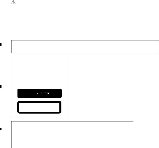
2.3PANEL FACILITIES
•DEH-63UB/XSUC, DEH-6300UB/XSUC
Head unit
1 2 |
3 |
4 |
5 6 |
|||||||||
|
|
|
|
|
|
|
|
|
|
|
|
|
|
|
|
|
|
|
|
|
|
|
|
|
|
|
|
|
|
|
|
|
|
|
|
|
|
|
|
|
|
|
|
|
|
|
|
|
|
|
|
|
|
|
|
|
|
|
|
|
|
|
|
|
|
|
|
|
|
|
|
|
|
|
|
|
|
|
c |
b a9 |
8 7 |
||
|
|
|
|
|
|
|
Part |
|
|
Part |
|
1 |
(list) |
|
7 |
Detach button |
|
|
|
|
|
|
|
|
MULTI-CONTROL |
|
AUX input jack |
||
2 |
8 |
(3.5 mm stereo |
|||
(M.C.) |
|
||||
|
|
|
|
jack) |
|
3 |
1 to 6 |
|
9 |
TAG/ (clock) |
|
|
|
|
|
|
|
4 |
Disc loading slot |
a |
BAND/ESC |
||
|
|
|
|
|
|
5 |
(eject) |
|
b |
SRC/OFF |
|
|
|
|
|
|
|
6 |
USB port |
|
c |
/DISP/SCRL |
|
|
|
|
|
|
|
 CAUTION
Use an optional Pioneer USB cable (CD-U50E) to connect the USB audio player/USB memory as any device connected directly to the unit will protrude out from the unit and may be dangerous.
Do not use unauthorized products.
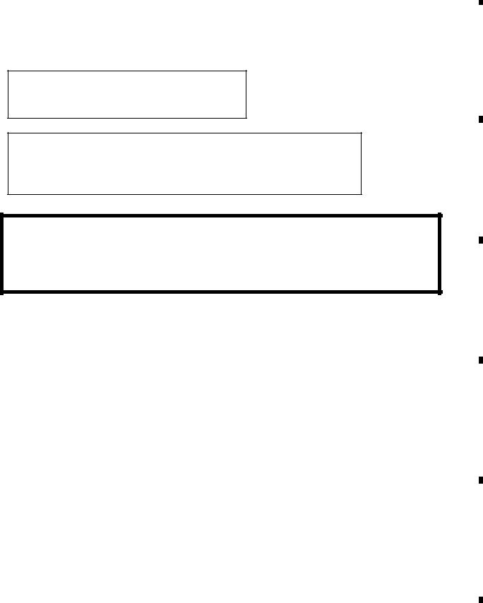
Remote control
|
|
d |
|
|
ak |
e |
|
|
|
f |
|
|
j |
g |
|
|
b |
h |
|
|
i |
|
|
|
Part |
Operation |
|
d |
VOLUME |
Press to increase or decrease |
|
volume. |
|||
|
|
||
e |
MUTE |
Press to mute. Press again to |
|
unmute. |
|||
|
|
Press to perform manual seek f / / / tuning, fast forward, reverse
and track search controls. Also used for controlling functions.
g AUDIO
Press to select an audio function.
Press to select different dis-
plays.
h DISP/SCRL Press and hold to scroll through the text information.
|
5 |
|
6 |
|
|
|
7 |
|
8 |
|
A
i |
|
Press to pause or resume play- |
|
|
back. |
|
|||
|
|
|
||
|
|
|
|
|
|
FUNC- |
Press to select functions. |
|
|
|
|
|||
j |
Press and hold to recall the ini- |
|
||
|
TION |
tial setting menu when the |
|
|
|
|
sources are off. |
|
|
|
|
|
|
|
|
|
Press to display the list de- |
|
|
k |
LIST/ |
pending on the source. |
|
|
|
ENTER |
While in the operating menu, |
B |
|
|
|
press to control functions. |
||
|
|
|
||
|
|
|
|
|
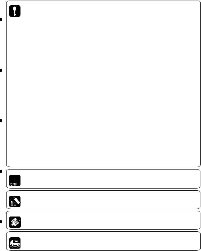
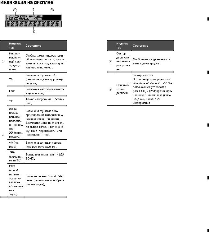
Display indication
1 2 3
4
C
Indicator State
Informa-
1tion disSource, band, and menu operplay secation guides are displayed.
tion
It displays while a song for which you can save informa-
TAG tion (tag) is playing.
It flashes while song information (tag) is being saved.
LOC |
Local seek tuning is on. |
D
The random function is on. 
 (ranThe iPod source is selected
2dom/shufand the shuffle or shuffle all fle/Quickfunction is on.
Mix) |
The pandora source is selected |
|
|||
|
|
|
and the QuickMix is selected. |
|
|
|
(re- |
The repeat function is on. |
|
||
|
|||||
peat) |
|
||||
|
|
|
|||
|
|
|
|
|
|
|
|
|
|
|
|
|
|
|
|
|
|
(sound re-
The sound retriever function is
triever)
on.
Level |
E |
3meter disThe levels of the audio outputs play secare displayed.
tion
Main dis-
Tuner: frequency
4 play sec-
Built-in CD ,USB and iPod:
tion
elapsed playback time and text information
F
DEH-6310SD/XSUR |
|
|
|
11 |
|
||
|
|
7 |
|
8 |
|
|
|
|
|
|
|
||||
1
A
• DEH-6310SD/XSUR
B
C
D
E
F
12
1
2 |
|
3 |
|
|
|
|
|
|
|
|
|
|
4 |
|
|||
|
|
|
|
|
|
|
|
|
|
|
|
|
|
|
|
|
|
|
|
|
|
|
|
|
|
|
|
|
|
|
|
|
|
|
|
|
|
|
|
|
|
|
|
|
|
|
|
|
|
|
|
|
|
|
|
|
|
|
|
|
|
|
|
|
|
|
|
|
|
|
|
|
|
|
|
|
|
|
|
|
|
|
|
|
|
|
|
|
|
|
|
|
|
|
|
|
|
|
|
|
|
|
|
|
|
|
|
|
|
|
|
|
|
|
|
|
|
|
|
|
|
|
|
|
|
|
|
|
|
|
|
|
|
|
|
|
|
|
|
|
|
|
|
|
|
|
|
|
|
|
|
|
|
|
|
|
|
|
|
|
|
|
|
|
|
|
|
|
|
|
|
|
|
|
|
|
|
|
|
|
|
|
|
|
|
|
|
|
|
|
|
|
|
|
|
|
|
|
|
|
|
|
|
|
|
|
|
|
|
|
|
|
|
|
|
|
|
|
|
|
|
|
|
|
|
|
|
|
|
|
|
|
|
|
|
|
|
|
|
|
|
|
|
|
|
|
|
|
|
|
|
|
|
|
|
|
|
|
|
|
|
|
|
|
|
|
|
|
|
|
|
|
|
|
|
|
|
|
|
|
|
|
|
|
|
|
|
|
|
|
|
|
|
|
|
|
|
|
|
|
|
|
|
|
|
|
|
|
|
|
|
|
|
|
|
|
|
|
|
|
|
|
|
|
|
|
|
|
|
|
|
|
|
|
|
|
|
|
|
|
|
DEH-6310SD/XSUR
2 |
|
3 |
|
4 |
|
|
|
|
|
5 |
|
6 |
|
7 |
|
8 |
|
A
• DEH-6310SD/XSUR
B
C
D
E
F
|
|
|
|
DEH-6310SD/XSUR |
|
|
|
13 |
|
||
|
5 |
|
6 |
|
|
7 |
|
8 |
|
|
|
|
|
|
|
|
|
||||||
|
1 |
|
2 |
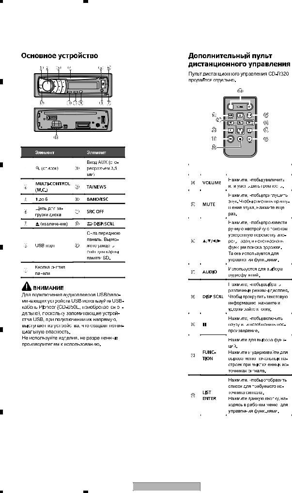
2.4 CONNECTION DIAGRAM
A
• DEH-63UB/XSUC, DEH-6300UB/XSUC
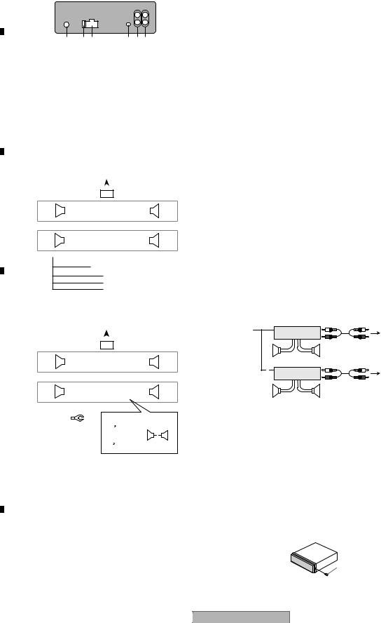
This unit
1 |
23 |
4 56 |
1Antenna input
2Fuse (10 A)
3Power cord input
4Wired remote input
B
Hard-wired remote control adaptor can be connected (sold separately).
5Rear output or subwoofer output
6Front output
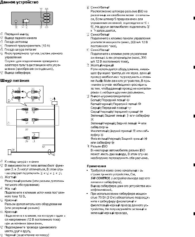
Power cord
Perform these connections when not connecting a rear speaker lead to a subwoofer.
|
|
|
|
|
|
|
|
|
|
|
|
|
1 |
|
|
|
|
|
|
|
|
|
|
|
|
|
L |
|
|
|
|
|
|
|
|
R |
|
||
|
|
|
|
|
|
|
|
|
|
|
|
|
|
|
|
|
|
||
|
|
|
|
|
2 |
|
|
|
|
|
|
|
|
|
|
3 |
|||
|
4 |
|
|
|
|
|
6 |
|
|
|
|
8 |
|
|
|
||||
C |
|
|
|
|
|
|
|
|
|
|
|
|
|
|
|
|
|
||
|
F |
|
|
|
|
|
|
|
7 |
|
|
|
|
9 |
|
|
|
|
|
|
|
|
|
|
|
|
|
|
|
|
|
|
|
||||||
|
5 |
|
|
|
|
|
|
|
|
|
|
|
|
||||||
|
|
|
|
|
|
|
a |
|
|
|
|
c |
|
|
|
||||
|
|
|
|
|
|
|
|
|
|
b |
|
|
|
|
d |
|
|
|
|
|
|
R |
|
|
|
|
|
|
|
|
|
|
|
|
|||||
|
|
|
|
|
|
|
|
|
|
||||||||||
|
|
|
|
|
|
|
|
|
|
|
|
|
|
|
|||||
|
|
|
|
|
|
|
|
|
|
|
|
|
|
|
|
|
|
|
|
 e
e
f g h
Perform these connections when using a subwoofer without the optional amplifier.
D |
|
|
|
|
|
|
|
|
1 |
|
|
|
|
|
|
|
|
|
|
|
|
|
|
|
|||||||||
|
|
|
|
|
|
|
L |
|
|
|
|
|
|
|
|
|
|
|
R |
|
|
|
|
|
|
||||||||
|
|
|
|
|
|
|
|
|
|
|
|
|
|
|
|
|
|
|
|
|
|
|
|
|
|
|
|
||||||
|
|
|
|
|
|
2 |
|
|
|
|
|
|
|
|
|
|
|
|
|
|
|
3 |
|
|
|
|
|
|
|||||
4 |
|
|
|
|
6 |
|
|
|
|
|
|
|
8 |
|
|
|
|
|
|
|
|
|
|
||||||||||
|
|
|
|
|
|
|
|
|
|
|
|
|
|
|
|
|
|
|
|
|
|
|
|
|
|
|
|
|
|
|
|||
|
|
F |
|
|
|
|
|
|
|
7 |
|
|
|
|
|
|
|
9 |
|
|
|
|
|
|
|
|
|
|
|
|
|
||
|
|
|
|
|
|
|
|
|
|
|
|
|
|
|
|
|
|
|
|||||||||||||||
|
i |
|
|
|
|
|
|
|
|
|
|
|
|
|
|
|
|
|
|
|
|||||||||||||
|
|
|
|
a |
|
|
|
|
|
|
|
c |
|
|
|
|
|
|
|
|
|
|
|||||||||||
|
|
SW |
|
|
|
|
|
|
b |
|
|
|
|
|
|
|
d |
|
|
|
|
|
|
|
|
|
|
|
|
||||
|
|
|
|
|
|
|
|
|
|
|
|
|
|
|
|
|
|
|
|
|
|
|
|
|
|||||||||
|
|
|
|
|
|
|
|
|
|
|
|
|
|
|
|
|
|
|
|
|
|
|
|
|
|
|
|||||||
|
|
|
|
|
|
|
|
|
|
|
|
|
|
|
|
|
|
|
|
|
|
|
|
|
|
|
|
|
|
|
|
|
|
|
|
|
|
|
|
|
|
|
|
|
e |
|
j |
c |
|
|
|
|
|||||||||||||||
|
|
|
|
|
|
|
|
|
|
|
|
|
|
||||||||||||||||||||
|
|
|
|
|
|
|
|
|
|
|
f |
|
|
|
|
|
|
a |
|
|
|
|
|
|
|
||||||||
|
|
|
|
|
|
|
|
|
|
|
|
|
|
|
|
|
|
|
|
|
|
|
|
|
|
|
|
|
|||||
|
|
|
|
|
|
|
|
|
|
|
g |
|
k |
|
|
|
|
|
|
|
|
|
|
|
|
|
l |
||||||
|
|
|
|
|
|
|
|
|
|
|
h |
|
|
|
|
|
|
b |
|
|
|
|
d |
|
|
|
|
|
|
|
|||
|
|
|
|
|
|
|
|
|
|
|
|
|
|
|
|
|
|
|
|
|
|
|
|
|
|
|
|
||||||
E |
|
|
|
|
|
|
|
|
|
|
|
|
|
|
|
|
|
|
|
|
|
|
|
|
|||||||||
|
|
|
|
|
|
|
|
|
|
|
|
|
|
|
|
|
|
|
|
|
|
|
|
|
|
|
|
||||||
1To power cord input
2Left
3Right
4Front speaker
5Rear speaker
6White
7White/black
8Gray
9Gray/black
aGreen
bGreen/black
Fc Violet
d Violet/black
14
|
1 |
|
2 |
|
|
|
3 |
|
4 |
|
eBlack (chassis ground)
Connect to a clean, paint-free metal location.
fYellow
Connect to the constant 12 V supply terminal.
gRed
Connect to terminal controlled by ignition switch (12 V DC).
hBlue/white
Connect to system control terminal of the power amp or auto-antenna relay control terminal (max. 300 mA 12 V DC).
iSubwoofer (4 Ω)
jWhen using a subwoofer of 70 W (2 Ω), be sure to connect the subwoofer to the violet and violet/black leads of this unit. Do not connect anything to the green and green/ black leads.
kNot used.
lSubwoofer (4 Ω)× 2
Notes
With a 2 speaker system, do not connect anything to the speaker leads that are not connected to speakers.
Change the initial setting of this unit. Refer
to SW CONTROL (rear output and subwoofer setting).
The subwoofer output of this unit is monaural.
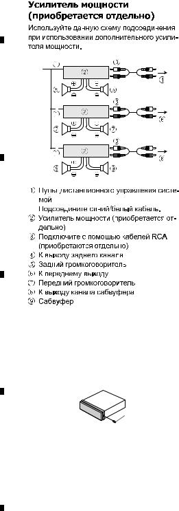
Power amp (sold separately)
Perform these connections when using the optional amplifier.
1 |
|
3 |
|
|
|
||
|
2 |
|
|
|
|
4 |
|
|
|||
5 |
|
5 |
|
|
|
|
|
|
|
3 |
|
1 |
2 |
|
|
|
6 |
||
|
|
||
|
|||
7 |
|
7 |
|
|
|
|
1 System remote control Connect to Blue/white cable.
2 Power amp (sold separately)
3 Connect with RCA cables (sold separately)
4 To Rear output or subwoofer output
5 Rear speaker or subwoofer
6 To Front output
7 Front speaker
Fastening the front panel
If you do not plan to detach the front panel,
the front panel can be fastened with the supplied screw.
Screw
UC : BPZ20P060FTC
DEH-6310SD/XSUR
|
3 |
|
4 |
|
|
|
|
|
5 |
|
6 |
|
7 |
|
8 |
|
A
• DEH-6310SD/XSUR
B
C
D
E
F
|
|
|
|
DEH-6310SD/XSUR |
|
|
|
15 |
|
||
|
5 |
|
6 |
|
|
7 |
|
8 |
|
|
|
|
|
|
|
|
|
||||||
|
1 |
|
2 |
|
3 |
|
4 |
|
A
• DEH-6310SD/XSUR
B
C
D
Fastening the front panel
If you do not plan to detach the front panel,
the front panel can be fastened with the supplied screw.
Screw
UR : XXX7020
E
F
16 |
DEH-6310SD/XSUR |
|
1 |
|
2 |
|
3 |
|
4 |
|
|
|
|
|
|
|
5 |
|
6 |
|
7 |
|
8 |
3. BASIC ITEMS FOR SERVICE
3.1 CHECK POINTS AFTER SERVICING
To keep the product quality after servicing, please confirm following check points.
No. |
|
Procedures |
Item to be confirmed |
1 |
|
Confirm whether the customer complain has |
The customer complain must not be |
|
|
been solved. |
reappeared. |
|
|
If the customer complain occurs with the |
Display, audio and operations must be |
|
|
specific media, use it for the operation check. |
normal. |
2 |
CD |
Play back a CD. |
No malfunction on display, audio and |
|
|
(Track search) |
operation. |
3 |
FM/AM tuner |
Check FM/AM tuner action. |
Display, audio and operations must be |
|
|
(Seek, Preset) |
normal. |
|
|
Switch band to check both FM and AM. |
|
4 |
|
Check whether no disc is inside the product. |
The media used for the operating check must |
|
|
|
be ejected. |
5 |
|
Appearance check |
No scratches or dirt on its appearance after |
|
|
|
receiving it for service. |
See the table below for the items to be checked regarding audio:
Item to be checked regarding audio
Distortion
Noise
Volume too low
Volume too high
Volume fluctuating
Sound interrupted
A
B
C
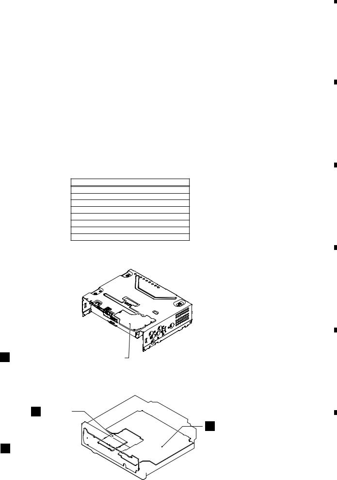
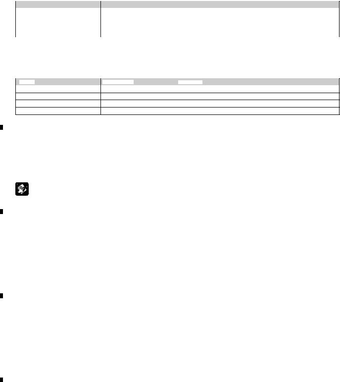
3.2 PCB LOCATIONS
|
A:DEH-6310SD/XSUR |
|
|
|
B:DEH-6300UB/XSUC |
D |
|
|
C:DEH-63UB/XSUC |
|
|
|
Unit Number |
: YWM5502(A) |
|
|
|
: YWM5504(B,C) |
|
|
Unit Name |
: Tuner Amp Unit |
|
|
Unit Number |
: (A) |
|
|
|
: (B,C) |
|
|
Unit Name |
: Keyboard Unit |
|
C CD Core Unit (S11.1STD-DOUT) |
Unit Number |
: CWX3985 |
|
Unit Name |
: CD Core Unit(S11.1STD-DOUT) |
|
|
|
Unit Number |
: YWM5516(A) |
|
|
Unit Name |
: SD Unit |
E |
D SD Unit
A Tuner Amp Unit
B Keyboard Unit 
F
|
|
|
|
DEH-6310SD/XSUR |
|
|
|
17 |
|
||
|
5 |
|
6 |
|
|
7 |
|
8 |
|
|
|
|
|
|
|
|
|
||||||
|
1 |
|
2 |
|
3 |
|
4 |
|
3.3JIGS LIST
-Jigs List
A
|
|
Name |
Jig No. |
Remarks |
|
|
16P FFC |
GGD1310 |
Tuner Amp Unit - CD Core Unit |
|
|
Test Disc |
TCD-782 |
Checking the grating |
|
|
L.P.F. |
|
Checking the grating (Two pieces) |
|
|
Acetate Tape |
GYH1026 |
Capacitor Bond Lock |
|
|
|
|
|
|
|
|
|
|
- Grease List
B |
|
|
|
|
|
Remarks |
|
|
|
|
|
|
|
|
|
|
|
|
|
|
|
|
CD Mechanism Module
CD Mechanism Module
CD Mechanism Module
CD Mechanism Module
3.4 CLEANING
C
Before shipping out the product, be sure to clean the following portions by using the prescribed cleaning tools:
Portions to be cleaned |
Cleaning tools |
CD pickup lenses |
Cleaning liquid : GEM1004 |
|
Cleaning paper : GED-008 |
D
E
F
18 |
DEH-6310SD/XSUR |
|
1 |
|
2 |
|
3 |
|
4 |
|
|
|
|
|
|

|
5 |
|
6 |
|
7 |
|
8 |
|
A
B
C
D
E
F
|
|
|
|
DEH-6310SD/XSUR |
|
|
|
19 |
|
||
|
5 |
|
6 |
|
|
7 |
|
8 |
|
|
|
|
|
|
|
|
|
||||||
|
1 |
|
2 |
|
3 |
|
4 |
|
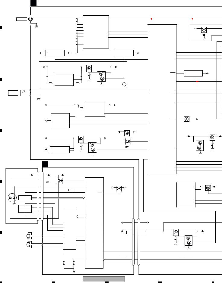
4. BLOCK DIAGRAM
4.1 BLOCK DIAGRAM
A |
A TUNER AMP UNIT |
|
|
|
|
|
|
|
|
|
|
|
|
|
|
|
|
|
|
|
|||||
|
|
|
|
|
|
|
|
|
|
|
|
|
|
|
|
|
|
|
|
||||||
|
|
|
|
|
|
|
|
|
|
|
|
RF FRONT END IC |
|
|
|
|
|
|
|
|
|
|
|
||
|
|
|
|
|
|
|
|
|
|
|
|
IC401 |
|
|
|
|
|
|
|
|
|
|
|
|
|
|
|
JA401 |
|
|
|
|
|
|
|
|
|
TDA7706 |
|
|
|
|
|
|
|
|
|
|
|
|
|
|
|
|
|
|
|
|
|
|
|
|
|
|
|
|
|
|
|
|
|
|
|
|
|
|
|
ANTENNA |
|
1 |
|
|
|
|
|
|
5 |
|
FMMIXIN1 |
DACOUTL |
57 |
|
|
|
|
|
|
|
|
|
TUNL |
||
|
|
|
|
|
|
|
|
18 |
|
|
|
|
|
|
|
|
|
|
|
|
|||||
|
2,3 |
|
|
|
|
|
|
|
LNAIN |
|
|
|
|
|
|
|
|
|
|
|
|
|
|||
|
|
|
|
|
|
|
1 |
|
|
|
|
|
|
|
|
|
|
|
|
|
|
||||
|
|
|
|
|
|
|
|
|
|
FMPINDRV |
|
|
|
|
|
|
|
|
|
|
|
|
|
||
|
|
|
|
|
|
|
|
|
8 |
|
|
|
|
|
|
|
|
|
|
|
Q201 |
|
|||
|
|
|
|
|
|
|
|
|
|
VCCRF |
|
|
|
|
|
|
|
|
|
|
|
||||
|
|
|
|
|
|
|
|
|
|
|
|
|
|
|
|
|
|
|
|
15V |
|
|
|||
|
|
|
|
|
|
|
|
|
13 |
|
|
|
|
|
|
|
|
|
|
|
|
|
|||
|
|
|
|
|
|
|
|
|
|
VCCVCO |
|
|
|
|
|
|
|
|
|
|
|
|
|||
|
|
|
|
|
|
|
|
|
|
|
|
34 |
|
|
76 |
|
|
|
|
|
|
|
|||
|
|
|
|
|
|
|
|
|
27 |
|
I2CSCL |
|
|
TUSCL |
|
|
|
|
|
|
|||||
|
|
|
|
|
|
|
|
|
|
VDIG |
|
|
|
|
|
|
|
|
|||||||
|
|
|
|
|
|
|
|
|
28 |
|
I2CSDA |
33 |
|
|
75 |
TUSDA |
|
|
|
|
|
|
|||
|
|
|
|
|
|
|
|
|
|
VCCREG1V2 |
|
|
|
|
|
|
|
|
|||||||
|
|
|
|
|
|
|
|
|
51 |
|
|
RSTN |
31 |
|
|
74 |
TUNRST |
|
|
|
|
|
|
||
|
|
|
|
|
|
|
|
|
|
VCC-REF |
|
|
|
|
|
|
|
|
CDL |
||||||
|
|
|
|
|
|
|
|
|
59 |
|
|
|
|
|
|
|
|
|
|
|
|
|
|||
|
|
|
|
|
|
|
|
|
|
VCC-ADC_DAC |
|
|
|
|
|
|
|
|
|
|
|
|
|||
|
|
|
|
|
|
|
|
|
|
|
|
|
|
|
|
|
|
|
|
|
|
|
|||
|
|
|
|
|
|
|
|
|
60 |
|
|
|
|
|
|
|
|
|
|
|
|
|
|
||
|
|
|
|
SYS+B REG. |
|
|
|
VCC-PLL |
|
|
|
TUNER 5V REG. |
|
|
|
|
|
|
|
|
|||||
|
|
|
|
|
|
|
|
|
|
|
|
|
|
|
|
|
|
|
|||||||
|
|
|
|
|
IC911 |
|
|
|
|
|
|
|
|
|
|
IC451 |
|
|
|
|
|
|
|
|
|
|
|
|
|
NJM2388F84 |
|
|
|
|
|
|
|
|
|
NJM2886DL3-05 |
|
|
|
|
|
|
|
|
|||
B |
|
SYS8V |
2 |
VOUT |
|
VIN |
1 |
BUP |
|
|
|
|
|
|
4 |
VOUT |
VIN |
2 |
|
VDT |
53 |
|
|
|
|
|
|
|
|
|
|
|
|
|
|
|
SYS8V |
|
|
54 |
|
|
|
|
|||||||
|
|
|
|
|
CONTROL |
|
|
|
|
|
|
|
|
|
|
CONT |
|
|
VCK |
|
|
|
|
||
|
|
|
|
|
|
4 |
|
|
|
|
|
|
|
|
|
|
1 |
|
|
55 |
|
|
|
|
|
|
|
|
|
|
|
|
|
|
|
|
|
|
|
|
|
46 |
|
VST |
|
|
|
|
|||
|
|
|
|
|
|
|
|
|
|
|
|
|
|
|
|
|
|
SYSPW |
|
|
|
|
|
||
|
|
|
|
|
|
|
|
|
|
|
|
|
|
|
|
|
|
|
|
|
|
|
|
||
|
|
|
|
|
|
|
|
HI-OUT 14V |
|
Q832 |
|
|
|
|
|
|
|
|
|
POWER ON RESET |
|
|
|||
|
|
|
|
|
|
|
|
|
|
|
|
|
|
|
|
|
|
|
|
|
|
|
|||
|
|
|
15V |
|
|
DC-DC CONVERTER |
|
|
|
|
|
|
|
BUP |
|
|
|
|
|
|
IC651 |
|
|
||
|
|
|
|
|
|
|
|
|
|
Q831 |
|
|
|
|
|
|
|
|
S-80827CNMC-B8M |
|
|
||||
|
|
|
|
|
|
IC831 |
|
|
|
|
|
|
|
|
|
|
|
|
|
|
|
|
|
||
|
|
|
|
|
|
NJM2360M |
|
|
|
|
|
|
|
|
|
|
|
|
RESET |
10 |
1 OUT |
VDD |
2 |
VDD33V |
|
|
|
|
|
|
1 |
CS |
|
V+ |
6 |
|
|
|
|
|
|
|
|
|
|
|
|
|
|
|
|
|
|
|
|
|
|
|
7 |
|
|
|
|
|
|
|
|
|
|
|
|
|
|
|
|
||
|
|
|
|
|
|
|
|
SI |
|
|
|
|
|
|
|
|
|
|
|
91 |
|
|
|
|
|
|
|
|
|
|
5 |
|
|
8 |
|
|
|
|
|
|
|
|
|
|
LVLINL |
|
|
|
|
||
|
|
|
|
|
INVIN |
|
CD |
|
|
|
|
|
|
|
A |
|
|
|
|
|
|
||||
|
|
|
|
|
|
|
|
|
|
|
|
|
|
|
|
|
|
|
|
|
|
|
|||
|
JA661 |
|
|
|
|
|
|
|
|
|
|
|
|
|
|
|
|
|
|
|
|
|
|
||
|
|
|
|
|
|
|
|
|
|
|
|
|
|
|
|
|
|
|
|
|
|
|
|
||
|
2 |
KEYAD |
|
|
|
|
|
|
|
|
|
|
|
|
|
|
|
92 |
KEYAD |
MUTE |
48 |
|
|
|
|
WIRED |
3 |
KEYD |
|
|
|
|
|
|
|
|
|
|
|
|
|
|
|
32 |
|
|
|
|
|
||
|
|
|
|
|
|
|
|
|
|
|
|
|
|
|
KEYD |
ASENS |
18 |
|
|
|
|
||||
|
|
|
|
|
|
|
|
|
|
|
|
|
|
|
|
|
|
|
|
|
|||||
REMOTE |
1 GND |
|
|
|
|
|
|
|
|
|
|
|
|
|
|
|
|
|
|
|
|
|
|
||
|
|
|
|
|
|
|
|
|
DD5V REG. |
|
|
|
|
|
SYSTEM MICRO |
|
|
|
|
|
|||||
|
|
|
|
|
|
|
|
|
|
|
|
|
|
|
|
|
|
|
|
|
|
||||
|
|
|
|
|
|
|
|
|
|
|
|
IC161 |
|
|
|
|
|
|
COMPUTER |
|
|
|
|
|
|
|
|
|
|
|
|
|
|
|
|
|
|
BD9008F |
|
|
|
|
|
IC601 |
|
|
|
|
|
|
|
C |
|
|
|
|
|
|
|
|
|
2 |
|
|
1 |
|
|
|
|
(1/2) |
TELIN |
40 |
|
|
|
|
|
|
|
DD5V |
|
|
|
|
|
|
SW |
PVIN |
|
BUP |
|
|
PEG730A8 : B,C |
|
|
|
|
|
|||||
|
|
|
|
|
|
|
|
4 |
8 |
|
|
|
|
|
|
|
|
||||||||
|
|
|
|
|
|
USB5V REG. |
|
|
INV |
VIN |
|
|
|
|
PEG729A8 : A |
|
|
|
|
|
|||||
|
|
|
|
|
|
|
|
|
|
|
|
|
|
|
|
|
|
|
|
||||||
|
|
|
|
|
|
IC151 |
|
|
|
|
|
|
|
|
|
|
|
|
|
|
|
|
|
|
|
|
|
|
|
|
|
R5523N001B |
|
|
|
|
EN/SYNC |
5 |
|
|
|
24 |
SYNC |
|
|
BSENS |
|
|
|
||
|
|
|
|
|
|
|
VIN |
4 |
|
|
|
|
|
|
|
|
|
|
|
|
|
Q921(1/2) |
|
|
|
|
|
|
|
|
|
|
|
|
|
|
|
|
|
|
|
|
|
|
|
16 |
|
|
|
|
|
|
|
USB5V |
5 |
VOUT |
|
|
|
|
|
|
|
|
|
|
|
|
|
BSENS |
|
BUP |
|
|
|||
|
|
EN |
1 |
|
|
|
|
|
|
|
|
|
36 |
USBCTL |
|
|
|
|
|
|
|||||
|
|
|
|
|
|
|
|
|
|
|
|
|
|
|
|
|
|
|
|
|
|
||||
|
|
|
|
|
|
|
FLG |
3 |
|
|
|
|
|
|
|
|
|
23 |
USBFLG |
|
|
|
|
|
|
|
|
|
|
|
|
|
|
|
|
|
|
|
|
|
|
|
SWVDD |
|
|
|
|
|
|
|
|
|
|
|
|
|
|
|
|
|
|
|
|
|
|
|
|
|
Q841 |
|
|
|
|
|
|
|
|
|
|
|
|
|
|
|
|
|
|
|
|
VDD5V REG. |
|
|
SWVDD |
|
VDD5V |
|
|
|
|
ILM+B |
Q823 |
||
|
|
|
|
|
|
|
|
|
Q901 |
|
|
|
|
|
|
|
|
|
|
|
BUP |
|
|
||
|
|
|
|
|
|
|
|
|
|
|
|
|
|
|
|
|
|
|
|
|
|
|
|
||
|
|
VDD5V |
|
|
|
|
|
|
|
|
|
|
BUP |
|
|
Q842 |
|
|
|
|
|
|
|
||
|
|
|
|
|
|
|
|
|
|
|
|
|
|
|
|
|
|
|
Q824 |
|
|
||||
|
|
|
|
|
|
VDD3.3V REG. |
|
|
|
|
Q902 |
|
|
|
|
|
47 |
SWVDD |
|
|
|
|
|
||
|
|
|
|
|
|
|
|
|
|
|
|
|
|
|
|
|
|
|
|
|
|||||
|
|
|
|
|
|
IC901 |
|
|
|
|
|
|
|
|
|
|
|
|
|
|
|
|
|
|
|
|
|
|
|
|
|
S-1132B33-U5 |
|
|
|
|
|
|
|
|
|
|
|
|
|
49 |
|
|
|
|
|
|
|
|
|
1 |
|
|
VIN |
5 |
|
|
|
|
|
|
|
|
|
45 |
|
ILMPW |
|
|
|
|
|
|
|
VDD33V |
VOUT |
|
|
|
|
|
|
|
|
|
DALMON |
|
|
|
|
|
|||||||
|
|
|
SW |
4 |
|
|
|
|
|
|
|
|
|
|
|
|
|
|
|
|
|||||
|
|
|
|
|
|
|
|
|
|
|
|
|
|
|
|
|
|
|
|
|
|
|
|
|
|
D |
|
|
|
|
|
|
|
|
|
|
|
|
|
|
|
|
|
19 |
|
|
|
|
|
|
|
|
|
|
|
|
|
|
|
|
|
|
|
|
|
|
|
|
|
VDCONT |
|
|
|
|
|
|
|
|
|
|
C CD CORE UNIT(S11.1STD-DOUT) |
|
|
|
|
|
|
MEDSTBY |
41 |
|
|
|
|
||||||||||
PICKUP UNIT |
|
|
|
|
|
|
|
|
|
|
|
|
|
||||||||||||
|
|
|
|
|
|
|
|
|
43 |
|
|
|
|
||||||||||||
|
|
|
|
|
|
|
|
|
MEDMUTE |
|
|
|
|
||||||||||||
(P10.5)(SERVICE) |
|
|
|
|
|
|
|
|
MED_TX |
33 |
|
|
|
|
|||||||||||
|
|
|
CN101 |
|
|
|
|
|
|
|
|
|
|
|
|
|
|
|
MED_RX |
34 |
|
|
|
|
|
|
|
|
|
|
|
RF AMP, CD DECODER, MP3&WMA DECODER |
|
|
|
|
|
|
|
|
|||||||||||
|
|
|
|
|
|
|
|
|
|
|
|
|
|
|
|||||||||||
|
VCC |
12 |
12 |
V+3A |
VDD |
|
DIGITAL SERVO/DATA • PROCESSOR |
|
|
|
|
|
|
|
|
|
|
||||||||
|
|
CPU, USB HOST CONTROLLER |
|
|
|
|
|
|
|
iPod CP |
|
|
|
||||||||||||
|
|
|
|
|
|
|
|
|
|
|
|
|
|
|
|
|
|
|
|||||||
LD |
|
LD- 15 |
15 GND |
Q101 |
|
|
|
1 |
LD |
|
|
|
|
|
|
|
|
|
IC591 |
|
|
|
|||
|
|
|
|
|
|
|
|
|
|
|
|
|
|
|
|
|
|
|
341S2162 |
|
|
|
|||
|
|
|
|
|
|
|
|
|
|
|
|
|
|
|
|
|
|
|
|
|
|
|
|
|
|
MD |
MD 5 |
|
PD |
|
2 PD |
|
|
Q102 |
|
2 |
Q591 |
|
5 |
|
|
V+3A |
VDD |
MODE1 |
MED33V |
||||||
|
VREF |
|
|
REFO |
REFO |
93 REFOUT |
|
54 |
|
VCC |
5 |
|
|
8 |
8 |
|
PUEN |
|
|
|
|
||||
|
|
|
|
|
|
|
|
|
|
|
|
|
|
HOLOGRAM |
|
|
|
AC,BD,E,F |
|
|
|
|
I2C_SCL |
12 |
|
|
UNIT |
|
|
|
|
IC201 |
|
|
|
13 |
|
|
|
|
|
|
|
|
|
|
|
|
|||
|
FOM |
|
|
FOM |
|
PE5756A |
|
|
I2C_SDA |
|
||
|
3 |
3 |
ACTUATOR/ |
|
|
|
|
nRESET |
4 |
|
||
|
FOCUS ACT. FOP 2 |
|
FOP |
|
|
|
|
|
|
|
||
E |
2 |
MOTOR DRIVER |
|
|
|
|
|
|
|
|||
TRACKING ACT. TOP 1 |
1 TOP |
|
IC301 |
|
|
|
|
|
|
|
|
|
|
|||
|
TOM |
|
4 TOM |
|
BA5839FP |
|
|
|
|
|
|
|
|
|
|
|
|
4 |
|
|
|
|
TD,FD |
|
|
|
CN701 |
|
|
CN701 |
|
||
|
LD+ 14 |
14 LD+ |
|
|
|
SD,MD |
|
|
|
|
|
|
||||
|
|
|
|
12 |
VO1+ |
|
|
|
|
|
VDD |
VDD |
9 |
8 |
VDD |
VDD33V |
|
|
|
|
11 |
VO1- |
|
|
|
|
|
|
|
||||
|
|
|
|
|
|
|
|
|
|
|
|
|
|
MECHA VD |
||
|
|
|
|
14 |
VO2+ |
|
|
|
|
|
|
|
|
|
|
|
|
|
|
|
13 |
VO2- |
|
|
|
|
|
|
VD |
|
|
VD |
Q751 |
|
|
|
|
|
|
|
|
|
VD |
2 |
15 |
BUP |
||||
SPINDLE |
M |
|
SOM |
15 |
VO3+ |
|
22 |
41 LOEJ |
|
|
|
1 |
16 |
|
Q752 |
|
MOTOR |
|
SOP |
16 |
VO3- |
LDIN |
|
|
|
|
|
|
|
||||
|
|
|
|
|
|
CNT |
21 |
40 CLCONT |
|
|
|
|
|
|
|
|
LOADING/CARRIAGE |
M |
|
LCOM |
17 |
VO4+ |
MUTE |
9 |
39 |
CONT |
|
|
|
|
|
|
|
|
LCOP |
18 |
|
|
|
|
|
|
|
|
|
|||||
MOTOR |
|
|
|
|
VO4- |
|
|
|
|
|
|
|
|
|
|
|
|
|
|
|
|
|
|
|
|
RESET |
29 |
|
RESET |
8 |
9 |
RESET |
|
|
|
|
|
|
|
|
|
38 DSCSNS |
|
|
|
|
|
|
|
|
F |
|
|
|
|
|
|
|
35 |
HOME |
|
CD DATA (CDSRQ,CDSTBY,SKIP, |
|
|
|
CD DATA (CDSRQ,CDSTBY,SKIP, |
|
|
|
|
|
|
|
|
|
|
|
SCL,SDA,DATA,BCLK,LRCK,WAIT) |
|
|
|
SCL,SDA,DATA,BCLK,LRCK,WAIT) |
||
|
|
|
|
S903 |
|
S901 |
|
|
|
|
|
|
|
|
|
|
|
|
|
|
DSCSNS |
HOME |
|
|
|
|
|
|
|
|
|
|
|
20 |
|
|
|
|
|
|
|
|
DEH-6310SD/XSUR |
|
|
|
|
|
||
1 |
|
|
|
|
|
|
2 |
|
|
|
|
3 |
|
|
4 |
|
|
|
|
|
|
|
|
|
|
|
|
|
|
||||
|
5 |
|
6 |
|
7 |
|
8 |
|
A
E. VOL
IC201
PM9012A
|
TUNL |
36 |
S4B-L |
|
|
|
|
|
|
|
|
|
|
|
|
Q201 |
|
|
|
OUTPL |
27 |
SWL |
|
|
20 |
|
|
|
|
|
|
|
|
VCCH |
|
26 |
RL |
|
|
|
|
|
|
|
|||
|
|
|
OUTRL |
|
|||
|
|
|
A |
OUTFL |
25 |
FL |
|
|
|
|
|
|
|||
|
CDL |
35 |
S5B+L |
|
|
Q303 |
Q302 |
|
|
|
|
|
|
|
|
|
AUXL |
39 |
S1Q+L |
|
|
|
|
|
|
|
|
|
|
|
|
|
|
23 |
DATA |
SOL |
31 |
MUTE |
A |
|
|
22 |
CLK |
|
|
Q382 |
|
|
|
|
|
BUP |
|
||
|
|
21 |
|
|
|
||
|
|
STB |
|
|
|
|
|
|
|
|
|
|
|
|
|
SET |
|
|
|
|
|
|
|
B8M |
|
|
|
|
|
MUTE |
|
VDD 2 |
|
|
|
AMP |
|
|
|
VDD33V |
|
|
|
Q381 |
|
||
|
|
|
|
IC241 |
|
|
|
|
|
|
NJM4558MD |
BUP |
|
||
|
|
|
1 |
+ |
3 |
|
|
|
|
|
|
- |
2 |
|
|
 BUP
BUP
|
|
|
|
|
|
|
|
|
|
|
|
|
|
|
|
|
|
MED33V REG. |
|
|
|
|
|
|
|
|
|
|
|
|
|
|
|
|
|
|
|
|
|
|
|
|
|
|
|
IC581 |
|
|
|
|
|
|
|
|
|
|
|
|
|
|
|
|
|
|
|
|
|
|
|
|
|
|
|
S-1172B33-E6 |
6 |
|
|
|
|
|
|
|
|
|
ILM+B |
MED33V |
|
|
|
|
|
1 |
|
VOUT |
VIN |
3 |
|
|
VDD5V |
||||||||||||
|
|
|
MED12V REG. |
|
|
|
ON/OFF |
|
|
DD5V |
|
|
|
||||||||||||||
|
|
|
|
Q823 |
|
|
|
|
|
|
|
|
|
|
|
|
|
|
|||||||||
|
|
|
|
|
|
|
|
|
|
|
|||||||||||||||||
|
|
|
|
|
|
|
|
|
ILM+B |
|
|
IC583 |
|
|
|
|
|
|
|
|
|
|
|
|
|
||
|
|
|
|
|
|
|
|
|
|
|
|
|
|
|
|
|
|
|
|
|
|
|
|
||||
|
|
|
|
|
|
|
|
|
|
|
|
BH12PB3WHFV |
|
|
|
|
|
|
|
|
|
|
|
|
|
||
Q824 |
|
|
|
|
|
|
3 |
|
|
|
|
|
|
|
|
|
|
|
|
||||||||
|
|
|
|
|
|
|
|
|
|
MED12V |
4 |
VOUT |
|
VIN |
|
|
|
|
|
|
|
|
|
|
|
|
|
|
|
|
|
|
|
|
|
|
|
1 |
|
|
|
|
|
|
|
|
|
|
|
|
|||||
|
|
|
|
|
|
|
|
|
|
|
|
STBY |
|
|
DAC |
|
|
|
|
|
|
|
|
|
|||
|
|
|
|
|
|
|
|
|
|
|
|
|
|
|
|
|
|
|
|
|
|
|
|
|
|||
|
|
|
|
|
|
|
|
|
|
|
|
|
|
|
|
|
|
|
|
|
|
|
|
|
|
||
|
|
|
|
|
|
|
|
|
|
MEDIA uCOM |
|
|
|
|
|
|
|
|
|
|
|
|
|
|
|||
|
|
|
|
|
|
|
|
|
|
|
|
|
|
|
|
|
|
|
|
|
|
|
|
||||
|
|
|
|
|
|
|
|
|
|
|
|
|
|
|
|
|
|
|
|
|
|
|
|
||||
|
|
|
|
|
|
|
|
|
|
|
IC501 |
|
|
|
|
|
IC181 |
|
|
|
|
|
|
|
|
|
|
|
|
|
|
|
|
|
|
|
|
R5S7262ZD144FPU |
|
|
|
WM8761GED |
|
|
|
|
|
|
|
|
|
||||
58 |
BRST |
|
|
|
137 |
2 |
|
|
|
9 |
|
|
|
|
|
CDL |
|
||||||||||
59 |
|
DACDATA |
|
DIN |
VOUTL |
|
|
|
|
|
|
||||||||||||||||
|
|
|
|
|
|
|
|
|
|||||||||||||||||||
MEDIAMUTE |
|
105 |
12 |
|
|
|
|
|
|
|
|
|
|||||||||||||||
|
|
|
|
|
|
|
|
|
|
|
|||||||||||||||||
61 |
|
DACDATA1 |
DEEMPH |
|
|
DAC5V REG. |
|
|
|
||||||||||||||||||
SYS_RXD |
|
|
|
|
|
|
|||||||||||||||||||||
|
|
136 |
14 |
|
|
|
|
|
|||||||||||||||||||
|
|
|
|
|
|
|
|
||||||||||||||||||||
63 |
SYS_TXD |
|
DACCLK |
|
MCLK |
|
|
|
|
IC182 |
|
|
|
||||||||||||||
|
138 |
1 |
|
|
|
|
|
|
|
||||||||||||||||||
|
|
|
|
|
|
|
|
|
|
|
|
||||||||||||||||
|
|
|
|
|
|
|
|
|
|
|
|
|
|||||||||||||||
|
|
|
|
|
|
|
|
|
|
|
|
DACLRCK |
|
LRCIN |
|
|
|
NJM2872F05 |
|
|
|
||||||
|
|
|
|
|
|
|
|
|
|
|
|
139 |
3 |
|
|
|
|
1 |
|
||||||||
|
|
|
|
|
|
|
|
|
|
|
|
DACSCK |
BCKIN |
VDD |
8 |
5 |
VOUT |
|
|
VIN |
|
|
|||||
|
|
|
|
|
|
|
|
|
|
|
|
|
|
|
|
|
|
|
|||||||||
|
|
|
|
|
|
|
|
|
|
|
|
|
|
|
|
|
|
|
|
|
3 |
|
|||||
|
|
|
|
|
|
|
|
|
|
|
|
|
|
|
|
|
|
|
|
|
|
CONT |
|
|
|||
|
|
|
|
|
|
|
|
|
|
|
|
|
|
|
|
|
|
|
|
|
|
|
|
|
|
|
|
|
|
|
|
|
|
|
|
|
|
|
|
|
|
|
|
|
|
|
|
|
|
|
|
|
|
|
|
|
|
|
|
|
|
|
|
|
|
|
|
|
|
|
|
|
|
|
|
|
|
|
|
|
|
|
|
Q591 |
MED33V |
111 CPPWR
149 CP_SCL
148 CP_SDA
112 CPRST
85
VDSENS
 BUP
BUP
SD_WP 115  MED33V
DM 70
71
DP |
|
|
|
|
|
|
FLASH ROM |
|
|
|
IC571 |
|
|
|
CWW2867 |
RESET |
43 |
12 |
RESET |
FLASH ROM
IC461
SST25V040BIS
B C
SD DATA (DATA0 - DATA3, CLK, CMD)
113
CDRST
SD_CD 114
|
|
|
|
|
JA301 |
|
B |
|
|
|
|
|
SWL/FR |
5 |
C |
|
|
|
|
|
FR/SWL |
4 |
|
|
|
|
|
|
|
|
RCA OUT |
|
|
|
|
|
RL |
2 |
A |
|
|
|
|
|
FL |
6 |
|
Q301 |
|
|
|
|
|
|
|
|
|
|
|
|
JA981 |
|
|
11 |
IN1 |
|
OUT1(+) |
9 |
FL1 |
1 |
B |
|
OUT1(-) |
7 |
FL2 |
3 |
|||
|
|
|
|
||||
12 |
IN2 |
|
OUT2(+) |
5 |
RL1 |
5 |
|
|
|
|
|||||
4 |
STBY |
AMP |
OUT2(-) |
3 |
RL2 |
7 |
|
SYS8V |
IC351 |
|
|
|
|
|
|
|
|
PA2030A |
|
|
|
|
|
MUTE |
|
|
|
|
|
|
|
Q361 |
|
|
|
25 |
BRE1 |
|
SOURCE |
22 |
MUTE |
H-SW/VOS-DET |
14 |
||||
|
|
|
|
|
|
CONNECTOR |
|
|
|
|
|
|
BUP |
18 |
|
|
|
ASENS |
|
|
|
|
|
|
|
Q921(2/2) |
|
|
|
|
|
|
|
|
|
|
ACC1 |
13 |
|
TELMUTE |
|
|
|
|
|
|
|
Q951 |
|
|
|
|
|
|
|
|
|
|
|
|
TEL1 |
9 |
|
|
|
|
|
|
|
C |
|
A |
|
|
|
|
|
|
|
|
|
|
|
CN801 |
|
|
|
|
|
|
|
|
|
|
|
|
|
|
|
|
AUXL |
14 |
|
|
|
2 |
|
|
ROT0 |
8 |
|
|
|
ROT0 |
|
|
|
|
|
|
|
1 |
|
|
ROT1 |
4 |
|
|
|
ROT1 |
|
|
|
|
|
|
|
95 |
|
|
JOYST |
6 |
|
|
|
JOYST |
|
|
|
|
|
|
|
KYDT 30 |
|
|
KYDT |
3 |
|
|
DPDT |
29 |
IC801 |
DPDT |
1 |
CN1 |
|
|
|
|
2 4 |
|
|
||||||
|
|
|
TC7SET08FUS1 |
|
|
|
|
|
|
|
SYSTEM MICRO |
|
|
|
|
|
|
D |
|
|
|
|
|
|
|
B |
|||
|
COMPUTER |
|
|
|
|
|
|
|
|
|
IC601 |
17 |
|
DSENS |
|
|
|
|
|
|
(2/2) DSENS |
|
20 |
|
|
|
|||
|
PEG730A8 : B,C |
|
|
|
|
|
|
|
|
|
PEG729A8 : A |
50 |
|
CLK |
|
|
|
|
|
|
RGBCK |
|
11 |
|
|
|
|||
|
|
|
|
|
|
|
|||
|
RGBDT |
52 |
|
DI |
12 |
|
|
|
|
|
|
|
|
|
|
|
|||
SYS8V |
RGBST |
51 |
|
LD |
9 |
|
|
|
|
|
|
|
|
|
|
||||
|
|
|
ILM+B |
|
10 |
|
|
|
|
|
|
|
|
|
|
|
|||
21 |
MEDRST |
|
SWVDD |
SW5V |
5 |
|
|
|
|
80 |
|
|
|
|
|
|
|||
SDCTL |
|
|
|
|
|
|
|
|
|
|
|
|
|
|
|
|
|
|
|
|
|
|
USB5V |
VBUS(US5V) |
13 |
|
|
|
|
|
|
|
|
D- |
15 |
|
|
|
|
|
|
|
|
|
|
|
|
||
|
|
|
|
D+ |
17 |
|
|
|
|
|
A :DEH-6310SD/XSUR |
|
|
|
|
E |
|||
|
|
|
|
|
|||||
|
B :DEH-6300UB/XSUC |
|
|
|
|
|
|
||
|
C :DEH-63UB/XSUC |
|
|
|
|
|
|
|
|
|
|
|
|
|
|
|
|
|
|
|
|
|
D SD UNIT |
|
|
CN781 |
|
|
CN1202 |
JA1203 |
|
SD33V REG. |
|
|
|
|
|
Q781 |
|
|
SD33V |
VDD |
SD CARD |
SD33V |
4 |
7 |
|||
MED33V |
|
4 |
|
||
SD_CD |
9 |
2 |
SD_CD |
CD1 10 |
|
Q782 |
|
|
|
|
|
Q783 |
|
|
|
|
|
F
A
|
|
|
|
DEH-6310SD/XSUR |
|
|
|
21 |
|
||
|
5 |
|
6 |
|
|
7 |
|
8 |
|
|
|
|
|
|
|
|
|
||||||
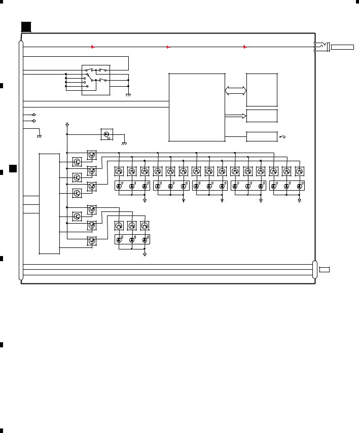
1  2
2  3
3  4
4
B KEYBOARD UNIT
CN1 |
CN3 |
|
AUXR 3 |
|
|
A |
AUXL 2 |
|
AUXL |
FRONT_AUX |
|
14 |
AUXG 1 |
|
|
|
ROT0 |
|
|
|
8 |
|
MULTI-CONTROL |
|
|
|
|
|
|
|
S13 |
|
ROT1 |
Phase_A 1 |
10 Phase_B |
|
4 |
A 3 |
2 Enc_Com |
|
JOYST |
|
||
6 |
B 4 |
|
|
|
5 Com |
|
|
|
C 7 |
|
|
|
|
|
|
|
D 8 |
6 GND |
|
|
Push 9 |
KDT1-3 |
KEY MATRIX |
|
|
||
|
|
KST1-4 |
|
3 |
KYDT |
49 |
TXD |
LCD DRIVER/ |
|
|
KEY CONTROLLER |
||
|
DPDT |
50 |
|
|
1 |
RXD |
IC1 |
||
|
|
|
|
PD6538A |
|
5 |
|
|
SW5V |
|
|
|
|
|
|
|
|
|
|
|
|
LCD |
|
|
|
|
|
|
10 |
|
|
ILM+B |
ILM+B |
|
|
|
|
|
|
|
|
|
|
LCD1 |
|
|
|
|
|
|
|
|
|
|
|
|
|
|
|
|
|
|
|
|
|
|
|
|
|
|
|||
B |
20 |
DSEN |
|
|
|
D13 |
|
|
|
|
|
|
|
|
REMOTE CONTROL |
|
|
|
|
|||
|
|
|
|
|
|
|
|
|
|
|
|
|
|
|
SENSOR |
|
|
|
|
|
||
|
|
|
|
|
|
|
|
|
|
|
|
|
REM |
57 |
1 |
|
IC2 |
|
|
|
|
|
|
|
|
|
|
|
|
|
|
|
|
|
|
|
|
|
GP1UXC14RK |
|
|
|
|
|
|
|
|
|
|
RGB DRIVER |
|
|
|
|
|
|
|
|
|
|
|
|
|
|
|
|
|
|
|
CN801 |
|
|
IC3 |
Q1 (1/2) |
|
|
|
|
|
|
|
|
|
|
|
|
|
|
|
|
|
|
|
|
BU2507FV |
RED |
|
|
|
|
|
|
|
|
|
|
|
|
|
|
|
|
||
|
|
|
|
|
|
|
|
|
|
|
|
|
|
|
|
|
|
|
|
|||
|
|
|
|
Q1 (2/2) |
GREEN |
|
|
|
|
|
|
|
|
|
|
|
|
|
|
|
|
|
|
|
|
Ao1 |
13 |
BLUE |
|
|
|
|
|
|
|
|
|
|
|
|
|
|
|
|
|
|
|
|
|
|
|
|
|
|
|
|
|
|
|
|
|
|
|
|
|
|||
|
A |
|
|
|
Q2 (1/2) |
Q7 (2/2) |
Q7 (1/2) |
Q8 (2/2) |
Q10 (1/2) |
Q10 (2/2) |
Q17 (1/2) |
Q11 (2/2) |
Q11 (1/2) |
Q17 (2/2) |
Q9 (1/2) |
Q9 (2/2) |
Q8 (1/2) |
Q18 (2/2) |
Q18 (1/2) |
Q19 (2/2) |
|
|
|
|
|
|
Q2 (2/2) |
|
|
|
|
|
|
|
|
|
|
|
|
|
|
|
|
|
|
|
|
|
|
|
|
|
|
|
|
|
|
|
|
|
|
|
|
|
|
|
|
|
|
|
|
|
Ao2 |
2 |
|
|
|
|
|
|
|
|
|
|
|
|
|
|
|
|
|
|
|
|
|
|
Q3 (1/2) |
|
|
|
|
|
|
|
|
|
|
|
|
|
|
|
|
|
|
|
|
|
|
Q3 (2/2) |
|
|
|
|
|
|
|
|
|
|
|
|
|
|
|
|
|
|
12 |
DI |
12 |
Ao3 |
3 |
D6 |
|
D7 |
|
|
D8 |
|
|
D9 |
|
|
D10 |
|
|
|
|
|
|
|
|
DI |
|
|
|
|
|
|
|
|
|
|
|
|
|
|
|
|
|
|
|
|
11 |
CLK |
11 |
CLK |
Q4 (1/2) |
RED |
ILM+B |
|
ILM+B |
|
ILM+B |
|
ILM+B |
|
ILM+B |
|
|
|||||
|
|
|
|
|
|
|
|
|
||||||||||||||
|
|
|
|
|
|
|
|
|
|
|
|
|
|
|
|
|
|
|
|
|
|
|
|
9 |
LD |
10 |
LD |
Q4 (2/2) |
GREEN |
|
|
|
|
|
|
|
|
|
|
|
|
|
|
|
|
C |
|
BLUE |
|
|
|
|
|
|
|
|
|
|
|
|
|
|
|
|
||||
|
|
5 |
|
|
|
|
|
|
|
|
|
|
|
|
|
|
|
|
||||
|
|
|
Ao4 |
|
|
|
|
|
|
|
|
|
|
|
|
|
|
|
|
|
||
|
|
|
|
|
Q5 (1/2) |
Q19 (1/2) |
Q12 (1/2) |
Q12 (2/2) |
|
|
|
|
|
|
|
|
|
|
|
|
|
|
|
|
|
|
Ao5 |
6 |
|
|
|
|
|
|
|
|
|
|
|
|
|
|
|
|
|
|
|
|
|
|
Q5 (2/2) |
|
|
|
|
|
|
|
|
|
|
|
|
|
|
|
|
|
|
|
|
|
Ao6 |
9 |
D11 |
|
|
|
|
|
|
|
|
|
|
|
|
|
|
|
|
|
|
|
|
|
|
|
ILM+B |
|
|
|
|
|
|
|
|
|
|
|
CN2 |
|
|
|
|
13 |
VBUS(US5V) |
|
|
|
|
|
|
|
|
|
|
|
|
|
|
VBUS(US5V) |
5 |
|
|||
|
15 |
D- |
|
|
|
|
|
|
|
|
|
|
|
|
|
|
|
|
|
D- |
4 |
USB |
|
17 |
D+ |
|
|
|
|
|
|
|
|
|
|
|
|
|
|
|
|
|
D+ |
3 |
|
|
|
|
|
|
|
|
|
|
|
|
|
|
|
|
|
|
|
|
|
|
||
D |
|
|
|
|
|
|
|
|
|
|
|
|
|
|
|
|
|
|
|
|
|
|
E
F
22 |
DEH-6310SD/XSUR |
|
1 |
|
2 |
|
3 |
|
4 |
|
|
|
|
|
|

|
5 |
|
6 |
|
7 |
|
8 |
5. DIAGNOSIS
5.1 OPERATIONAL FLOWCHART
Power ON
VCC = 3.3 V
Pin 14
BSENS
Pin 16
BSENS = L
ASENS
Pin 18
ASENS = L
DSENS
Pin 17
Starts communication with Grille microcomputer.
SWVDD <- H
Pin 47
Source keys operative
Source ON
SYSPW <- H
Pin 46
500 ms
500 ms
In case of the above signal, the communication with Grille microcomputer may fail.
If the time interval is not 500 msec, the oscillator may be defective.
Completes power-on operation.
(After that, proceed to each source operation)
|
|
|
|
DEH-6310SD/XSUR |
|
|
|
23 |
||
|
5 |
|
6 |
|
|
7 |
|
8 |
|
|
|
|
|
|
|
||||||
A
B
C
D
E
F

|
1 |
|
2 |
|
3 |
|
4 |
|
5.2 ERROR CODE LIST
A  ERROR CODES
If a CD memory device is inoperable, or operation of such media is stopped by an error, the error mode is established and a cause of the error is displayed by an error code. Indication of error codes is intended to reduce the number of calls from customers and facilitate failure analysis and repair work in servicing.
(1) DISPLAY METHOD
If “0xFD” error mode is displayed in CD MODE (CD MODE area for display), an error code will be displayed in the MIN (minute display) and SEC (second display) areas.
The same code is displayed in the MIN and SEC areas. The TNO area is blank (#0FFH), as it conventionally was.
• Display example of the main unit
B
Depending on the display capability of LCDs, the display format varies, as shown below. XX denotes an error number. Note: In a case of an OEM product, the error display format is subject to the specifications used by the equipment
manufacturer.
|
|
|
|
8-digit display |
6-digit display |
4-digit display |
||||||||
|
|
|
|
|
|
|
|
|
|
|
|
|
||
|
|
|
|
ERROR-xx |
|
|
ERR-xx |
|
|
|
E-xx |
|
||
|
|
(2) LIST OF CD ERROR CODES (Error Mode: 0xFD) |
|
|
||||||||||
|
|
|
|
|
|
|
|
|
|
|
|
|
||
C |
Code |
Classification |
Error code to be displayed |
|
|
|
|
Details and possible causes |
||||||
|
|
7 |
|
Servo |
TOC reading NG |
|
TOC information cannot be read. |
|||||||
|
|
|
|
|
|
|
|
|
|
--> The partial disk or TOC content is illegal. |
||||
|
|
|
|
|
|
|
|
|
|
|
|
|
||
|
|
10 |
|
Servo |
Carriage Home NG |
|
The CRG cannot move toward the inner track. |
|||||||
|
|
|
|
|
|
|
|
|
|
The CRG cannot move from the inner track. |
||||
|
|
|
|
|
|
|
|
|
|
--> Defective HOME SW; Failure in CRG movement. |
||||
|
|
11 |
|
Servo |
Focus Search NG |
|
Focusing not available |
|||||||
|
|
|||||||||||||
|
|
|
|
|
|
|
|
|
|
--> Disc placed upside-down; Stains on the disc; excessive vibration. |
||||
|
|
12 |
|
Servo |
Spindle Lock NG |
|
Spindle not locked. Subcode not readable. |
|||||||
|
|
|
|
|
Subcode NG |
|
|
Proper RF AMP gain not obtained. |
||||||
|
|
|
|
|
RF-amp NG |
|
|
--> Defective spindle; Scratches or stains on the disc; excessive vibration. |
||||||
|
|
|
|
|
|
|
|
|
|
--> A CD-R disc that does not contain data loaded, or in a rare case, disc placed upside-down. |
||||
D |
|
|
|
|
|
|
|
|
--> CD signal error. |
|||||
|
|
|
|
|
|
|
|
|
|
|
|
|
||
|
|
15 |
|
Servo |
Failure in RF data |
|
RF not read |
|
|
|||||
|
|
|
|
|
|
|
|
|
|
--> A CD-R disc that does not contain data loaded |
||||
|
|
|
|
|
|
|
|
|
|
--> A CD-RW disc that does not contain data loaded |
||||
|
|
|
|
|
|
|
|
|
|
|
|
|
|
|
|
|
17 |
|
Servo |
Setup NG |
|
|
AGC protection does not work. Focus can be easily lost. |
||||||
|
|
|
|
|
|
|
|
|
|
--> Scratches or stains on the disc; excessive vibration. |
||||
|
|
|
|
|
|
|
|
|
|
|
|
|
||
|
|
30 |
|
Servo |
Search Time Out |
|
Failed to reach a target address |
|||||||
|
|
|||||||||||||
|
|
|
|
|
|
|
|
|
|
--> CRG tracking error; Scratches on the disc; Stains on the disc |
||||
|
|
|
|
|
|
|
|
|
|
|
|
|
||
|
|
50 |
|
Mechanism |
Failure in ejection |
|
Disc ejection not completed |
|||||||
|
|
|
|
|
Load NG |
|
|
Disc loading not completed |
||||||
|
|
|
|
|
|
|
|
|
|
--> A foreign object inserted in the mechanism; Disc jammed. |
||||
|
|
|
|
|
|
|
|
|
|
|
|
|
||
E |
51 |
|
Mechanism |
Failure in retried |
|
Disc could not be ejected even after disc turning had been retried. |
||||||||
|
|
|
turning for ejection |
|
--> A foreign object inserted in the mechanism; Disc jammed. |
|||||||||
|
|
|
|
|
|
|
|
|
|
|
|
|
|
|
NOTES
•Indications of error codes are available only during disc operations, because CD operations are unavailable if a mechanical error is generated.
•If the TOC cannot be read, this is not processed as an error, and operation continues accordingly.
• If you design a new head unit, be sure to use one of the display formats indicated in “Display example of the main unit.”
|
• The 2 high-order digits of an error code denote the main |
• How to restore from each error is shown below. |
|
classification, shown below. |
0x, 1x and 3x: ACC-OFF then ON, CD-OFF then ON, |
|
0x: Servo-related errors |
Disc ejection |
|
1x: Servo-related errors |
5X: ACC-OFF then ON, Disc ejection, Disc reloading |
F |
3x: Servo-related errors |
|
5x: Mechanism-related errors |
|
24 |
DEH-6310SD/XSUR |
|
1 |
|
2 |
|
3 |
|
4 |
|
|
|
|
|
|

|
5 |
|
6 |
|
7 |
|
• DEH-63UB/XSUC, DEH-6300UB/XSUC
USB storage device/iPod
|
Message |
Cause |
Action |
|
|||
|
|
|
|
NO DEVICE |
When plug and |
Turn the plug |
|
|
|
play is off, no |
and play on. |
|
|
USB storage deConnect a com- |
|
|
|
vice or iPod is |
patible USB stor- |
|
|
connected. |
age device/iPod. |
|
|
|
|
FORMAT |
Sometimes |
Wait until the |
|
READ |
there is a delay |
message disap- |
|
|
|
between the |
pears and you |
|
|
start of playback |
hear sound. |
|
|
and when you |
|
|
|
start to hear any |
|
|
|
sound. |
|
|
|
|
|
NO AUDIO |
There are no |
Transfer the audio |
|
|
|
songs. |
files to the USB |
|
|
|
storage device |
|
|
|
and connect. |
|
|
|
|
|
|
The connected |
Follow the USB |
|
|
USB storage destorage device in- |
|
|
|
vice has secur- |
structions to dis- |
|
|
ity enabled |
able the security. |
|
|
|
|
SKIPPED |
The connected |
Play an audio file |
|
|
|
USB storage denot embedded |
|
|
|
vice contains |
with Windows |
|
|
files embedded |
Media DRM 9/10. |
|
|
with Windows |
|
|
|
Media™DRM 9/ |
|
|
|
10 |
|
|
|
|
|
PROTECT |
All the files in |
Transfer audio |
|
|
|
the USB storage |
files not em- |
|
|
device are em- |
bedded with |
|
|
bedded with |
Windows Media |
|
|
Windows Media |
DRM 9/10 to the |
|
|
DRM 9/10 |
USB storage de- |
|
|
|
vice and connect. |
|
|
|
|
N/A USB |
The connected |
Connect a USB |
|
|
|
USB storage deMass Storage |
|
|
|
vice is not sup- |
Class compliant |
|
|
ported by this |
device. |
|
|
unit. |
Disconnect |
|
|
|
your device and |
|
|
|
replace it with a |
|
|
|
compatible USB |
|
|
|
storage device. |
|
|
|
|
|
|
Non-compatible |
Disconnect your |
|
|
iPod |
device and re- |
|
|
|
place it with a |
|
|
|
compatible iPod. |
|
|
|
|
|
|
|
|
|
Message |
Cause |
Action |
|
|
|
|
CHECK USB |
The USB con- |
Check that the |
|
|
|
nector or USB |
USB connector or |
|
|
cable has short- |
USB cable is not |
|
|
circuited. |
caught in some- |
|
|
|
thing or dam- |
|
|
|
aged. |
|
|
|
|
|
|
The connected |
Disconnect the |
|
|
USB storage deUSB storage de- |
|
|
|
vice consumes |
vice and do not |
|
|
more than 500 |
use it. Turn the |
|
|
mA (maximum |
ignition switch to |
|
|
allowable cur- |
OFF, then to ACC |
|
|
rent). |
or ON and then |
|
|
|
connect only |
|
|
|
compliant USB |
|
|
|
storage devices. |
|
|
|
|
|
|
The iPod oper- |
Make sure the |
|
|
ates correctly |
connection cable |
|
|
but does not |
for the iPod has |
|
|
charge |
not shorted out |
|
|
|
(e.g., not caught |
|
|
|
in metal objects). |
|
|
|
After checking, |
|
|
|
turn the ignition |
|
|
|
switch OFF and |
|
|
|
back ON, or dis- |
|
|
|
connect the iPod |
|
|
|
and reconnect. |
|
|
|
|
ERROR-19 |
Communication |
Perform one of |
|
|
|
failed. |
the following op- |
|
|
|
erations. |
|
|
|
–Turn the ignition |
|
|
|
switch OFF and |
|
|
|
back ON. |
|
|
|
–Disconnect the |
|
|
|
USB storage de- |
|
|
|
vice. |
|
|
|
–Change to a dif- |
|
|
|
ferent source. |
|
|
|
Then, return to |
|
|
|
the USB source. |
|
|
|
Disconnect the |
|
|
|
cable from the |
|
|
|
iPod. Once the |
|
|
|
iPod's main menu |
|
|
|
is displayed, re- |
|
|
|
connect the iPod |
|
|
|
and reset it. |
|
|
|
|
|
|
iPod failure |
Disconnect the |
|
|
|
cable from the |
|
|
|
iPod. Once the |
|
|
|
iPod's main menu |
|
|
|
is displayed, re- |
|
|
|
connect the iPod |
|
|
|
and reset it. |
|
|
||
ERROR-23 |
USB storage deUSB storage de- |
||
|
|
vice was not for- |
vice should be for- |
|
|
matted with |
matted with |
|
|
FAT12, FAT16 or FAT12, FAT16 or |
|
|
|
FAT32 |
FAT32. |
|
|
|
|
DEH-6310SD/XSUR
|
5 |
|
6 |
|
|
|
7 |
|
|
|
|
|
|
|
8
A
B
C
D
E
F
25
8

|
1 |
|
2 |
|
3 |
|
4 |
|
A
Pandora
|
|
|
Message |
Cause |
Action |
|
|
|
|||
|
|
|
|
|
|
|
|
ERROR-16 |
The iPod firm- |
Update the iPod |
|
|
|
|
|
ware version is |
version. |
|
|
|
|
old |
|
|
|
|
|
iPod failure |
Disconnect the |
|
|
|
|
|
cable from the |
|
|
|
|
|
iPod. Once the |
|
|
|
|
|
iPod's main menu |
|
|
|
|
|
is displayed, re- |
B |
|
connect the iPod |
|||
|
and reset it. |
||||
|
|
|
|
|
|
|
|
STOP |
There are no |
Select a list that |
|
|
|
|
|
songs in the |
contains songs. |
|
|
|
|
current list. |
|
|
|
|
|
|
|
|
|
NOT FOUND |
No related |
Transfer songs to |
|
|
|
|
|
songs |
the iPod. |
|
|
|
|
|
|
|
|
|
|
|
|
C
D
|
Message |
Cause |
Action |
|
|||
|
|
|
|
ERROR-19 |
Communication |
Disconnect the |
|
|
|
failed. |
cable from the |
|
|
|
iPod. Once the |
|
|
|
iPod's main menu |
|
|
|
is displayed, re- |
|
|
|
connect the iPod |
|
|
|
and reset it. |
|
|
|
|
START UP |
The Pandora apStart up the |
||
APP |
plication has |
Pandora applica- |
|
|
|
not started run- |
tion from your |
|
|
ning yet. |
iPod/iPhone. |
|
|
|
|
TRY AGAIN |
Unable to save |
Try again later. |
|
|
|
thumb rating. |
|
|
|
Unable to save |
|
|
|
BookMark. |
|
|
|
Pandora system |
|
|
|
is undergoing |
|
|
|
maintenance. |
|
|
|
|
|
SKIP LIMIT |
Skip limit |
Do not exceed the |
|
|
|
reached. |
skip limit. |
|
|
|
|
CHECK APP |
This version of |
Connect an iPod/ |
|
|
|
the Pandora ap- |
iPhone that has a |
|
|
plication is not |
compatible ver- |
|
|
supported. |
sion of the |
|
|
|
Pandora applica- |
|
|
|
tion installed. |
|
|
|
|
CHECK DE- |
Device error |
Please check your |
|
VICE |
message dis- |
iPod/iPhone. |
|
|
|
played in |
|
|
|
Pandora Appli- |
|
|
|
cation. |
|
|
|
Unable to play |
|
|
|
music from |
|
|
|
Pandora. |
|
|
|
|
|
NO STATION |
No station |
Create a station |
|
|
|
found. |
in the Pandora |
|
|
|
application on |
|
|
|
your iPod/iPhone. |
|
|
|
|
NO ACTIVE |
No station se- |
Select a station. |
|
ST |
lected. |
|
|
|
|
|
|
E
F
26 |
DEH-6310SD/XSUR |
|
1 |
|
2 |
|
3 |
|
4 |
|
|
|
|
|
|
Loading...