


ORDER NO.
CRT4033
DEH-4090MP/XN/ID
CD RECEIVER
DEH-4090MP/XN/ID
DEH-6010MP/XN/UR
This service manual should be used together with the following manual(s):
Model No. |
Order No. |
Mech.Module |
Remarks |
||||||||
|
|
|
|
|
|
|
|
|
|
|
|
CX-3195 |
CRT3815 |
S10.5COMP2 |
CD Mech. Module : Circuit Descriptions, Mech. Descriptions, Disassembly |
||||||||
|
|
|
|
|
|
|
|
|
|
|
|
|
|
|
|
|
|
|
|
|
|
|
|
|
|
|
|
|
|
|
|
|
|
|
|
|
|
|
|
|
|
|
|
|
|
|
|
|
|
|
|
|
|
|
|
|
|
|
|
|
|
|
|
|
|
|
|
|
|
|
|
|
|
|
|
|
|
|
|
|
|
|
|
|
|
|
|
|
|
|
|
|
|
|
|
For details, refer to "Important Check Points for Good Servicing".
PIONEER CORPORATION 4-1, Meguro 1-chome, Meguro-ku, Tokyo 153-8654, Japan
PIONEER ELECTRONICS (USA) INC. P.O. Box 1760, Long Beach, CA 90801-1760, U.S.A.
PIONEER EUROPE NV Haven 1087, Keetberglaan 1, 9120 Melsele, Belgium
PIONEER ELECTRONICS ASIACENTRE PTE. LTD. 253 Alexandra Road, #04-01, Singapore 159936
 PIONEER CORPORATION 2007
K-ZZW. OCT. 2007 Printed in Japan

A
B
C
D
E
F
1 |
|
2 |
|
3 |
|
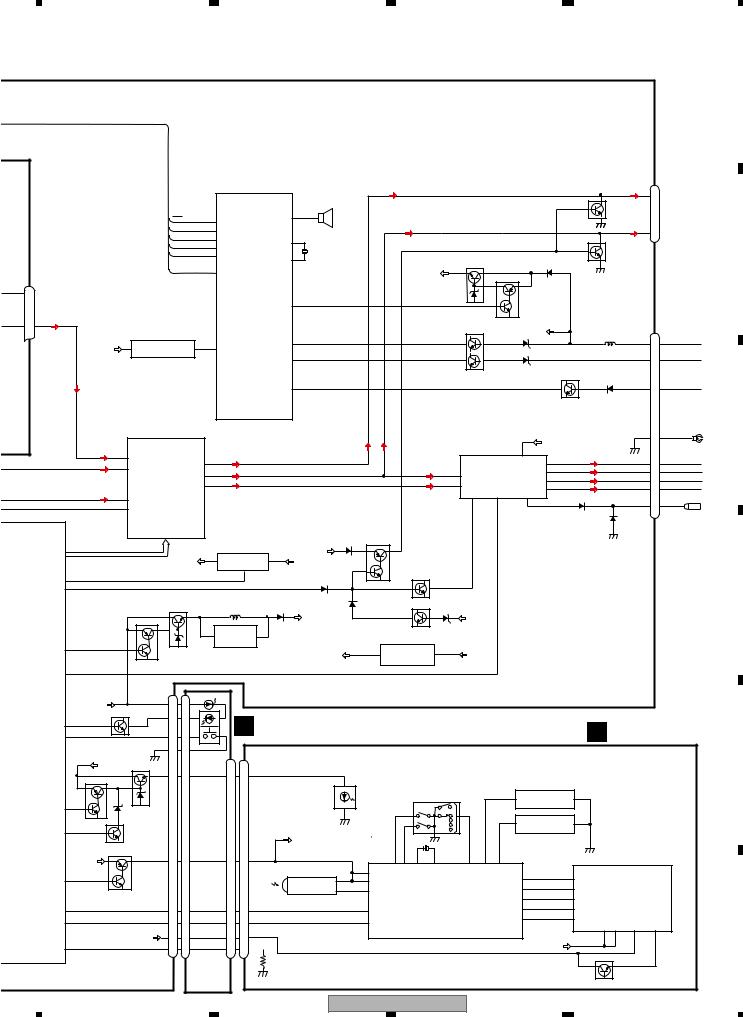
4. BLOCK DIAGRAM
A TUNER AMP UNIT
|
|
|
|
|
|
|
|
|
|
|
VDD |
TUNPDO |
TUNPCK |
|
|
|
TUNPDI |
|
|
|
|
|
|
||||||
|
|
|
|
|
|
|
|
|
|
|
|
|
|
|
|
|
|
|
|
|
|||||||||
|
|
|
|
|
|
|
|
|
|
|
|
|
|
|
|
|
|
|
|
|
|
|
|
|
|
|
|
|
|
|
|
7 |
6 |
|
|
|
13 |
5 |
10 |
9 |
8 |
11 |
14 |
18 |
19 |
20 |
21 |
||||||||||||
FM/AM TUNER UNIT |
|
NC |
|
CE2 |
_VDD |
|
SL |
|
DI |
CK |
|
CE1 |
NC |
|
|
|
DO |
NC |
NC |
NC |
NC |
||||||||
|
|
|
|
|
|
|
|
|
ROM |
|
|
|
|
|
|
|
|
|
|
|
|
|
|
|
|
|
|
|
|
|
|
|
|
|
|
|
|
|
|
|
|
|
|
|
|
|
|
|
|
|
|
|
|
|
|
|
|
|
|
|
|
|
|
|
|
|
|
|
|
|
|
|
|
|
|
|
|
|
|
|
|
|
|
|
|
|
|
|
|
|
|
|
|
|
|
|
|
|
|
|
|
|
|
|
|
|
|
|
|
|
|
|
|
|
|
|
|
|
|
|
|
|
|
|
|
|
|
|
|
|
|
|
|
|
|
|
|
|
|
|
|
|
|
|
|
|
|
|
|
|
|
|
IC 3 EEPROM |
|
|
|
|
|
IC 5 |
|
|
|
|
|
|
|
|
|
|
|
|
|
|
||||||
|
|
|
|
|
5.0V |
|
|
|
5V t 3.3V |
|
|
|
|
|
|
|
|
|
|
|
|
||||||||
|
|
|
|
|
|
|
|
|
|
|
|
|
|
|
|
|
|
|
|||||||||||
|
|
|
|
|
|
|
|
|
|
|
|
|
|
|
|
|
|
|
|
|
|
|
|
|
|
|
|
|
|
OSC 

 LPF
LPF
ANTENNA ANT401 |
|
AM ANT |
FMRF |
1 |
|
||
|
|
||
1 |
ATT |
|
|
|
|
2,3
|
|
|
|
|
|
|
|
|
|
|
|
|
|
|
|
|
|
|
|
|
|
|
|
|
|
|
|
|
|
|
|
|
|
|
|
|
|
|
|
|
|
|
|
|
|
|
|
|
|
|
|
|
IC 2 |
|
|
|
|
|
|
|
|
|
|
|
|
|
|
|
|
|
|
|
|
|
|
|
|
|
|
|
|
|
|
|
|
|
|
|
|
|
|
|
|
|
|
|
|
|
|
|
|
|
|
|
|
|
|
|
FM ANT |
|
|
|
|
|
|
|
|
|
|
|
|
|
|
IC 1 |
|
|
|
|
|
|
|
|
|
|
|
|
|
|
|
|
|
|
|
|
|
|
|
|
|
|
|
|
|
|
|
2.5V |
|||||
3 |
|
|
ATT |
|
|
|
|
|
|
|
|
|
|
|
|
|
|
3.3V |
|
|
|
|
|
|
|
|
|
|
|
|
|
|
|
|
|
|
|
|
|
|
|
|
|
|
|
|
|
|
|
|
|||
|
|
FMRF |
|
|
|
|
|
|
|
|
|
MIXER, IF AMP |
|
|
|
|
|
|
|
|
|
|
|
|
|
|
|
|
|
|
|
|
|
|
|
DET, FM MPX |
|||||||||||||||||
|
|
|
|
|
|
|
|
|
|
|
|
|
|
|
|
|
|
|
|
|
|
|
|
|
|
|
|
|
|
|
|
|
|
|
|
|
|
||||||||||||||||
|
|
|
|
|
|
|
RF adj |
|
|
|
|
|
|
|
|
|
|
|
|
|
|
|
|
|
|
|
|
|
|
|
|
|
|
|
|
|
|
|
|
|
|
|
|
|
|
|
|
|
|
|
|
|
|
|
|
|
ANT adj |
|
|
|
|
|
|
|
|
|
|
|
|
|
|
|
|
|
|
|
|
|
|
|
|
|
|
|
|
|
|
|
|
|
|
|
|
|
|
|
|
|
|
|
|
||||||
|
|
|
|
|
|
|
|
|
|
|
|
|
|
|
|
|
|
|
|
|
|
|
|
|
|
|
|
|
|
|
|
|
|
|
|
|
|
|
|
|
|
|
|
|
|
|
|
|
|
|
|
|
|
|
|
|
|
|
|
|
|
|
|
|
|
|
|
|
|
|
|
|
|
|
|
|
|
|
|
|
|
|
|
|
|
|
|
|
|
|
|
|
|
|
|
|
|
|
|
|
|
|
|
|
|
|
|
|
|
|
|
|
|
|
|
|
|
|
|
|
|
|
|
|
|
|
|
|
|
|
|
|
|
|
|
|
|
|
|
|
|
|
|
|
|
|
|
|
|
|
|
|
|
|
|
|
|
|
|
|
|
|
|
|
|
|
|
|
|
|
|
|
|
|
|
|
|
|
|
|
|
|
|
|
|
|
|
|
|
|
|
|
|
|
|
|
|
|
|
|
|
|
|
|
|
|
|
|
|
|
|
|
|
|
|
|
|
|
|
|
|
|
|
|
|
|
|
|
|
|
|
|
|
|
|
|
|
|
|
|
|
|
|
|
|
|
|
|
|
|
|
|
|
|
|
|
|
|
|
|
|
|
|
|
|
|
|
|
|
|
|
|
|
|
|
|
|
|
|
|
|
|
|
|
|
|
|
|
|
|
|
|
|
|
|
|
|
|
|
|
|
|
|
|
|
|
|
|
|
|
|
|
|
|
|
|
|
|
|
|
|
|
|
|
|
|
|
|
|
|
|
|
|
|
|
|
|
|
|
|
|
|
|
|
T51 |
|
|
|
CF52 |
|
|
|
|
|
|
|
|
|
|
|
|
|
|
|
|
|
|
|
|
|
|
|
|
|
|
||
|
|
|
|
|
|
|
|
|
|
|
|
|
|
|
|
|
|
|
|
|
|
|
|
|
|
|
|
|
|
|
|
|
|
|
|
|
|
|
|
|
|
|
|
|
|
|
|
|
|
|
|||
|
|
|
|
|
|
|
|
|
|
|
|
|
|
|
|
|
|
|
|
|
|
|
|
|
|
|
|
|
|
|
|
|
|
|
|
|
|
|
|
|
|
|
|
|
|
|
|
|
|
|
|
|
|
|
|
|
|
|
|
|
|
|
|
|
|
|
|
|
|
|
|
|
|
|
|
|
|
|
|
|
|
|
|
|
|
|
|
|
|
|
|
|
|
|
|
|
|
|
|
|
|
|
|
|
|
|
|
|
|
|
|
|
|
|
|
|
|
|
|
|
|
|
|
|
|
|
|
|
|
|
|
|
|
|
|
|
|
|
|
|
|
|
|
|
|
|
|
|
|
|
|
|
|
|
|
|
|
|
|
|
|
|
|
|
|
|
|
|
|
|
|
|
|
|
|
|
|
|
|
|
|
|
|
|
|
|
|
|
|
|
|
|
|
|
|
|
|
|
|
|
|
|
|
|
|
|
|
|
|
|
|
|
|
|
|
|
|
|
|
|
|
|
|
|
|
|
|
|
|
|
|
|
|
AUDIOGND |
|
|
|
|
|
|
|
|
|
|
|
|
|
|
|
|
|
|
|
|
|
|
|
|
|
|
|
|
|
|
|
|
|||
|
|
|
|
|
|
|
|
|
|
|
|
|
|
|
RFGND |
OSCGND |
DGND |
NC |
VCC |
|
|
|
VDD3.3 |
|
|
|
|
IC 4 |
|
|
|
|
|
|
|
|
|
|
|
|
|
|
|
|
|
|
|||||||
|
|
|
|
|
|
|
|
|
|
|
|
|
|
|
|
|
|
|
|
|
|
|
|
|
|
|
|
|
|
|
|
|
|
|
|
|
|
|
|
||||||||||||||
|
|
|
|
|
|
|
|
|
|
|
|
|
|
|
|
|
|
|
|
|
|
|
|
|
|
|
|
|
|
3.3V |
3.3V t 2.5V |
2.5V |
|
|
|
|
|
|
|
|
|
|
|
|
|
|
|||||||
|
|
|
|
|
|
|
|
|
|
|
|
|
|
|
|
|
|
|
|
|
|
|
|
|
|
|
|
|
|
|
|
|
|
|
|
|
|
|
|
|
|
|
|
|
|
||||||||
|
|
|
|
|
|
|
|
|
|
|
|
|
|
|
|
|
|
|
|
|
|
|
|
|
|
|
|
|
|
|
|
|
|
|
|
|
|
|
|
|
|
|
|
|
|
|
|
|
|
|
|
|
|
|
|
|
|
|
|
|
|
|
|
|
|
|
|
|
|
|
|
|
|
|
|
|
|
|
|
|
|
|
|
|
|
|
|
|
|
|
|
|
|
|
|
|
|
|
|
|
|
|
|
|
|
|
|
|
2 |
12 |
15 |
22 |
16 |
4 |
17 |
|
|
|
|
|
|
|
|
|
|
|
|
|
|
|
|
|
|
|
|
|
|
|
|
||||||||||||||||||||||
 3.3V
3.3V
CN151
|
6 |
|
|
AUX |
5 |
AUXL |
|
4 |
AUXG |
||
|
D CD CORE UNIT(S10.5COMP2)
PICKUP UNIT |
|
|
D |
|
|
|
|
RF-AMP, CD DECODER, |
|
|
|
|
|
|
|
|
||||||
(P10.5)(SERVICE) |
|
|
|
|
|
MP3/WMA DECODER, |
|
|
|
|
|
|
|
|
||||||||
|
|
|
|
|
|
DIGITAL SERVO / |
|
|
|
|
|
|
|
|
|
|||||||
|
|
|
|
|
|
CN101 |
|
VDD |
|
|
DATA PROCESSOR |
|
|
|
|
|
|
|
|
DSENS |
||
LASER |
|
|
|
|
|
|
|
|
|
|
|
|
|
|
|
|
|
|
|
S801 |
||
|
|
|
|
|
|
|
|
|
|
|
|
|
|
|
|
|
|
|
|
|||
DIODE |
|
|
LD- 15 |
15 |
|
|
|
|
|
141 |
LD |
|
|
|
|
|
|
|
|
|
|
|
|
|
|
|
Q101 |
|
|
|
|
|
|
|
|
|
|
|
|
|
|||||
|
|
|
MD |
5 |
5 |
|
REFO |
|
|
142 |
PD |
LOUT |
55 |
|
|
|
|
|
|
|
|
|
|
|
|
VREF |
|
|
|
|
|
133 |
|
|
|
|
|
|
|
|
|
|
|||
|
|
|
8 |
8 |
|
|
|
|
|
REFOUT |
|
|
|
|
|
|
|
|
|
|
||
|
HOLOGRAM |
|
|
|
|
|
AC,BD,F,E |
|
|
|
|
|
|
|
|
|
|
|
|
|
||
|
|
|
|
|
|
|
|
|
|
|
|
|
|
|
|
|
|
|
|
|
||
|
UNIT |
|
|
|
|
|
|
|
|
|
|
|
|
|
|
|
|
|
|
|
|
|
|
|
|
FOM |
3 |
3 |
FOM |
|
CD |
|
|
|
|
|
|
|
|
|
|
|
|
|
|
MONITOR |
FOCUS ACT. |
FOP |
2 |
2 |
FOP |
|
DRIVER |
|
|
|
|
|
|
|
|
|
|
|
|
|
||
TRACKING ACT. |
TOP |
1 |
1 |
TOP |
|
|
|
|
|
|
|
|
|
|
|
|
|
|
|
|
||
DIODE |
|
|
TOM |
4 |
4 |
TOM |
|
IC301 |
|
|
|
XTAL |
50 |
|
|
|
|
|
|
|
|
|
|
|
|
LD+ |
14 |
14 |
|
|
BA5839FP |
TD,FD |
IC201 |
|
X201 |
CN701 |
|
CN701 |
|
|
|
||||
|
|
|
|
|
|
|
12 |
FOM |
|
|
|
PE5547A |
52 |
16.93MHz |
|
|
|
|
|
|
|
|
|
|
|
|
|
|
|
|
|
|
|
/XTAL |
|
|
|
|
|
|
|
|
|||
|
|
|
|
|
|
|
11 |
FOP |
|
SD,MD |
|
|
|
|
LOUT |
13 |
3 |
CDL |
|
|
|
|
|
|
|
|
|
|
|
14 |
TOP |
|
|
|
|
|
39 |
VDD |
|
|
|
|
|
|
|
|
|
|
|
|
|
|
13 |
TOM |
|
|
|
|
|
|
|
|
|
|
VDD 3.3V REGULATOR |
|||
|
|
|
|
|
|
|
|
|
|
|
|
|
|
|
|
|
|
|||||
|
SPINDLEMOTOR |
M |
|
|
|
|
|
|
|
|
|
|
|
|
Q102 |
VDD |
|
|
CDVDD |
3 |
IC780 |
1 |
|
|
|
|
|
|
|
|
|
|
|
|
VCC |
|
9 |
7 |
|||||||
|
|
|
|
|
|
|
16 |
SOP |
|
22 |
5 |
|
|
|
|
|
|
NJM2885DL1-33 |
VDD |
|||
|
|
|
|
|
|
|
LOEJ |
LOEJ |
|
|
|
|
|
|
|
|
|
|||||
|
|
|
|
|
|
|
15 |
SOM |
|
|
|
|
|
|
|
|
|
|
|
|
|
|
|
|
|
|
|
|
|
|
21 |
43 |
|
/PUEN |
|
|
|
|
|
|
|
|
|
||
LOAD/ CARRIAGE |
M |
|
|
|
|
18 |
LCOP |
CLCONT |
CLCONT |
|
|
|
|
|
|
|
|
|
||||
|
|
|
|
|
|
|
|
|
|
|
|
|
|
|
|
|||||||
|
MOTOR |
|
|
|
|
17 |
LCOM |
CONT |
9 |
41 |
CONT |
/RESET |
16 |
|
/RESET |
8 |
8 |
CDRST |
|
|
|
|
|
|
|
|
|
|
|
|
|
|
|
|
|
|
|
|
|||||||
|
|
|
|
|
|
|
|
|
|
|
|
|
|
|
BRST,BRXEN,BSRQ |
|
|
|
|
BRST,BRXEN,BSRQ,BDATA,BSCK |
||
|
|
|
|
|
|
|
|
|
|
|
8 |
12EJ |
|
|
BDATA,BSCK |
|
|
|
|
Q751 VD 7.5V REGULATOR |
||
|
|
|
|
|
|
|
|
|
|
|
7 |
8EJ |
|
|
|
VD |
2 |
|
VD |
|
|
|
|
|
|
|
|
|
|
|
|
|
|
6 |
|
|
VD |
14 |
|
|
BUP |
||||
|
|
|
|
|
|
|
|
|
|
|
DSCSNS |
|
|
|
|
1 |
15 |
|
|
Q752 |
|
|
|
|
|
|
|
|
|
|
|
|
|
9 |
HOME |
|
|
|
|
|
|
|
|
||
|
|
|
|
|
|
S904 |
S905 |
|
|
S901 |
|
|
|
|
|
|
|
|
|
|
|
|
|
|
|
|
|
|
12EJ |
8EJ |
|
|
HOME |
|
|
|
|
|
|
|
|
|
|
|
|
|
|
|
|
|
|
|
|
|
|
|
|
|
|
|
VD |
|
|
|
|
|
|
|
|
|
|
|
|
|
|
|
S903 |
|
|
|
|
|
|
|
|
|
|
|
|
|
|
|
|
|
|
|
|
|
|
DSCSNS |
|
|
|
VDSENS |
11 |
|
|
|
|
|
|
|
|
|
|
|
|
|
|
|
|
|
|
|
|
|
|
|
|
|
|
|
|
|
|
|
|
4
Rch 24
Lch 23
2
VDD
|
|
|
E |
TUNL |
6 |
|
|
|
I |
||
CDL |
7 |
|
I |
|
|
|
|
AUXL |
2 |
|
I |
AUXG |
1 |
|
I |
|
|
|
SYSTEM
CONTROLLER
IC 601(2/2)
PEG404A
SYSPW 46
MUTE 39
OELPW 48
AMPPW 68
9 |
DSENS |
BUP |
|
Q801
FLPILM 50
8
EJTIN
ILM CONTRO
BUP |
Q823 |
|
ILMPW |
49 |
|
|
DIM |
36 |
Q8 |
|
|
|
SWVDD |
21 |
CDRST |
|
VDD |
|
|
||
|
SWVDD |
47 |
|
|
|
|
|
|
|
|
Q892 |
|
DPDT |
33 |
|
|
|
|
|
|
KYDT |
34 |
|
|
|
|
|
20 |
VDCONT |
|
|
|
|
|
|
|
CSENS |
91 |
|
|
|
|
16 |
DEH-4090MP/XN/ID |
|
1 |
|
2 |
|
3 |
|
4 |
|
|
|
|
|
|
|
|
5 |
|
|
|
|
|
|
|
|
|
|
6 |
|
|
|
|
|
|
|
|
7 |
|
|
|
|
|
|
|
|
|
|
|
8 |
|
|
|
|
|
|
|
|
|
|
|
|
|
|
|
|
|
|
|
|
|
|
|
|
|
|
|
|
|
|
|
|
|
|
|
|
A |
|
|
|
|
|
|
|
|
|
|
|
|
|
|
|
|
|
|
|
|
|
|
|
|
|
|
|
|
|
MUTE |
|
|
CN301 |
|
||
|
|
|
|
|
|
|
|
|
|
|
|
|
|
|
|
|
|
|
|
|
|
|
|
|
|
|
|
|
SWL |
|
|
|
|
||
|
|
|
|
|
|
|
|
|
|
|
|
|
BZ601 |
|
|
SWL |
|
|
|
|
|
|
|
|
|
|
|
|
|
|
|
|
5 |
|
|
|
|
|
|
|
|
|
|
|
|
|
|
|
|
|
|
|
|
|
|
|
|
|
|
|
|
|
|
|
|
|
|
|
|
||
|
|
|
|
|
|
|
|
|
|
|
|
|
BUZZER |
|
|
|
|
|
|
|
|
|
|
|
|
|
|
|
|
|
|
|
|
|
|
|
|
|
|
|
|
|
|
|
|
|
|
24 |
|
|
|
|
|
|
|
|
|
|
|
|
|
|
|
|
|
|
Q303 |
|
|
RCA OUT |
|
|
|
|
|
CE2 |
|
63 |
TUNPCE2 |
|
PEE |
|
|
|
|
|
|
|
|
|
|
|
|
|
|
|
|
|
|
|
|
|
|
||||
|
|
|
|
|
|
|
|
|
|
|
|
|
|
|
|
|
|
|
|
|
|
|
|
|
|
|
|
|
|
|
|||||
|
|
|
|
CE1 |
|
64 |
TUNPCE1 |
|
|
|
|
|
|
FL |
|
|
|
|
|
|
|
|
|
|
|
|
|
FL |
|
|
6 |
|
|||
|
|
|
|
TUNPDI |
|
66 |
|
|
13 |
|
|
|
|
|
|
|
|
|
|
|
|
|
|
|
|
|
|
|
|
|
|
||||
|
|
|
|
TUNPDO |
|
|
TUNPDI |
|
XIN |
|
|
|
|
|
|
|
|
|
|
|
|
|
|
|
|
|
|
|
|
|
|
|
|||
|
|
|
|
|
67 |
|
|
|
|
|
|
|
|
|
|
|
|
|
|
|
|
|
|
|
|
|
|
|
|
|
|||||
|
|
|
|
|
TUNPDO |
|
|
|
X601 |
|
|
|
|
|
|
|
|
|
|
|
|
|
|
|
|
|
Q302 |
|
|
|
B |
||||
|
|
|
|
TUNPCK |
|
65 |
TUNPCK |
|
XOUT |
11 |
15.00MHz |
|
|
|
|
|
|
|
VDD REGULATOR |
|
|
|
|
|
|
|
|
|
|||||||
|
|
|
|
|
|
|
|
|
|
|
|
|
|
|
|
|
|
|
|
|
|
|
|
|
|||||||||||
|
|
|
|
SL |
|
|
|
|
|
|
|
|
|
|
|
|
|
|
|
|
Q901 |
|
|
|
|
|
|
|
|
|
|
|
|
|
|
|
|
|
|
|
|
95 |
SL |
SYSTEM |
|
|
|
|
|
|
|
|
|
VDD |
|
|
|
|
|
|
|
|
|
|
|
|
|
|
|
||
|
|
|
|
|
|
|
|
|
|
|
|
|
|
|
|
|
|
Q902 |
|
|
|
|
|
|
|
|
|
|
|
|
|||||
|
|
|
|
|
|
|
|
CONTROLLER |
|
|
|
|
|
|
|
|
|
|
|
|
|
|
|
|
|
|
|
|
|
|
|
||||
Rch 24 |
|
|
|
|
|
|
|
|
IC 601(1/2) |
|
|
|
|
|
|
|
|
|
|
|
|
|
|
|
|
|
|
|
|
|
|
|
|
||
|
|
|
|
|
|
|
|
PEG404A |
|
|
|
|
|
|
|
|
|
|
|
|
|
|
|
|
|
|
|
|
|
|
|
|
|
||
|
|
|
|
|
|
|
|
|
|
DALMON |
45 |
|
|
|
|
|
|
|
|
|
|
|
|
|
|
|
|
|
|
|
|
|
|
|
|
Lch 23 |
|
|
|
|
|
|
|
|
|
|
|
|
|
|
|
|
|
|
|
|
BSENS |
|
|
|
BUP |
|
|
|
|
|
CN981 |
|
|||
|
|
|
RESET |
|
|
|
|
|
|
|
|
|
|
|
|
|
|
|
|
|
|
|
|
|
|
|
|
|
|
|
|
||||
|
|
|
|
|
|
|
|
|
|
16 |
|
|
|
|
|
|
|
|
|
|
|
|
|
|
|
|
|
|
|
|
BUP |
|
|
||
|
|
2 |
IC651 |
1 |
|
10 |
|
|
|
BSENS |
|
|
|
|
|
|
|
|
|
|
|
|
|
|
|
|
|
|
|
|
16 |
B.UP |
|||
|
VDD |
|
RESET |
|
|
|
|
|
|
|
|
|
|
Q921 |
|
|
|
|
|
|
|
|
|
|
|
|
|||||||||
|
|
S-80835CNMC-B8U |
|
|
|
|
|
|
|
|
|
|
|
|
|
|
|
|
|
|
|
|
|
|
|
|
|
|
|||||||
|
|
|
|
|
|
|
|
|
73 |
|
|
|
|
|
|
|
|
|
|
|
|
|
|
|
|
|
|
ACC |
|
|
|||||
|
|
|
|
|
|
|
|
|
|
|
ASENS |
|
|
|
|
|
|
|
|
|
|
|
|
|
|
|
|
|
|
|
|
14 |
ACC |
||
|
|
|
|
|
|
|
|
|
|
|
|
|
|
|
|
|
|
|
|
|
ASENS |
|
|
|
|
ILM SENS |
|
|
|
|
|
|
|||
|
|
|
|
|
|
|
|
|
|
|
|
|
|
|
|
|
|
|
|
|
|
|
|
|
|
Q931 |
|
|
|
|
|
|
|||
|
|
|
|
|
|
|
|
|
|
|
ISENS |
51 |
|
|
|
|
|
|
|
|
|
|
|
|
|
|
|
|
|
|
|
|
ILL |
12 |
ILL |
|
|
|
|
|
|
|
|
|
|
|
|
|
|
|
|
|
|
|
|
|
|
|
|
|
|
|
|
|
|
|
|
|
|||
|
|
ELECTRONIC VOLUME/ |
|
|
|
|
|
|
|
|
|
|
|
|
|
|
|
|
|
|
|
|
|
|
|
|
|
|
|
|
C |
||||
|
|
|
SOURCE SELECTOR |
|
|
|
|
|
|
|
|
|
|
|
|
|
|
|
|
|
|
|
|
|
|
|
|
|
|
|
GND |
15 |
GND |
||
|
|
|
|
|
|
|
|
|
|
|
|
|
|
|
|
|
|
|
|
|
|
|
|
|
|
BUP |
|
|
|
|
|
|
|||
|
|
|
|
|
|
|
|
|
|
|
|
|
|
|
|
|
|
|
|
|
|
|
|
|
|
|
|
|
|
|
|
|
|
||
|
TUNL |
6 |
IN2_L |
|
|
|
|
|
|
|
|
|
|
|
|
|
|
|
|
|
POWER AMP |
|
6,20 |
|
|
|
|
|
|
|
|
|
|||
|
|
|
|
12 |
|
|
|
|
|
|
|
|
|
|
|
|
|
|
|
VCC |
FL- |
23 |
|
|
|
FL- |
|
FL2 |
|
|
|||||
|
CDL |
7 |
|
Pre/SW_L |
|
|
|
|
|
|
|
|
|
|
|
|
|
|
|
|
|
|
|
7 |
FL- |
||||||||||
|
IN1_L |
|
|
|
|
|
|
|
|
|
|
|
|
|
|
|
|
|
|
|
21 |
|
|
|
FL+ |
FL1 |
|||||||||
|
|
|
|
|
|
|
|
|
|
|
|
|
|
|
|
|
IC 351 |
|
|
|
|
|
|
|
|
||||||||||
|
|
|
|
Front_L |
10 |
|
|
|
|
|
|
|
|
|
|
|
|
14 |
FLIN |
|
|
|
FL+ |
|
|
|
5 |
FL+ |
|||||||
|
|
|
IC201 |
11 |
|
|
|
|
|
|
|
|
|
|
|
|
12 |
|
PAL007C |
|
|
RL- |
3 |
|
|
|
RL- |
|
RL2 |
8 |
RL- |
||||
|
|
|
Rear_L |
|
|
|
|
|
|
|
|
|
|
|
|
RLIN |
|
|
|
|
RL+ |
5 |
|
|
|
RL+ |
RL1 |
|
|||||||
|
|
|
PML018A |
|
|
|
|
|
|
|
|
|
|
|
|
|
|
|
STBY |
|
|
|
|
|
6 |
RL+ |
|||||||||
|
AUXL |
2 |
IN5+_L |
|
|
|
|
|
|
|
|
|
|
|
|
|
|
|
|
|
MUTE |
B.REM |
|
|
|
|
|
|
|
|
|
||||
|
|
|
|
|
|
|
|
|
|
|
|
|
|
|
|
|
|
22 |
|
4 |
25 |
|
|
|
|
|
|
|
BEM 11 |
|
|||||
|
AUXG |
1 |
IN5-_L |
|
|
|
|
|
|
|
|
|
|
|
|
|
|
|
|
|
|
|
|
|
|
|
|
|
B.REM |
||||||
|
|
|
|
|
|
|
|
|
|
|
|
|
|
|
|
|
|
|
|
|
|
|
|
|
|
|
|
|
|
|
|
|
|
|
|
SYSTEM |
|
|
|
|
|
|
|
|
|
|
|
|
|
|
MUTING |
|
|
|
|
|
|
|
|
|
|
|
|
|
|
|
|
|
|
||
|
|
|
|
|
|
|
|
|
|
|
|
|
|
|
Q381 |
|
|
|
|
|
|
|
|
|
|
|
|
|
|
|
|
|
|
|
|
CONTROLLER |
|
|
|
|
|
|
SYS +B REGULATOR |
|
|
|
|
|
|
|
|
|
|
|
|
|
|
|
|
|
|
|
|
|
|
|
|||||
VST,VCK,VDT |
|
|
|
|
BUP |
|
|
|
|
|
|
|
|
|
|
|
|
|
|
|
|
|
|
|
|
|
|
||||||||
IC 601(2/2) |
|
|
|
|
|
|
2 |
|
IC911 |
|
|
|
|
|
|
|
|
|
|
|
|
|
|
|
|
|
|
|
|
|
|
|
|
||
PEG404A |
|
|
|
|
VCC |
|
|
1 |
BUP |
|
|
|
|
|
|
|
|
|
|
|
|
|
|
|
|
|
|
|
|
|
|
||||
|
|
|
|
|
|
|
NJM2388F84 |
|
|
|
|
|
|
|
|
|
|
|
|
|
|
|
|
|
|
|
|
|
|
|
|||||
|
|
|
|
|
|
|
|
|
|
|
|
|
|
|
|
|
|
|
|
|
|
|
|
|
|
|
|
|
|
|
|
|
|||
|
46 |
|
|
|
|
|
|
|
4 |
|
|
|
|
|
|
|
|
|
MUTE |
|
|
|
|
|
|
|
|
|
|
|
|
|
|
|
|
SYSPW |
|
|
|
|
|
|
|
|
|
|
|
|
|
|
|
|
Q351 |
|
|
|
|
|
|
|
|
|
|
|
|
|
|
|
|
||
MUTE |
39 |
|
|
|
|
|
|
|
|
|
|
|
|
|
|
|
|
|
|
|
|
|
|
|
|
|
|
|
|
|
|
|
|
|
D |
|
|
|
|
|
|
|
|
|
|
|
|
|
|
|
|
|
|
|
E-MUTE |
|
|
|
|
|
|
|
|
|
|
|
|
|
|
||
|
|
|
|
Q561 |
|
|
|
|
|
|
|
|
|
|
|
|
|
|
|
|
|
|
|
|
|
|
|
|
|
|
|
|
|||
|
|
|
|
|
|
|
|
|
|
|
|
|
|
|
|
Q391 |
|
|
|
|
|
|
|
|
|
|
|
|
|
|
|
|
|||
|
|
|
Q562 |
|
|
|
|
|
|
|
|
|
OEL14V |
|
|
|
|
|
|
|
BUP |
|
|
|
|
|
|
|
|
|
|
|
|
|
|
|
|
|
|
|
|
|
|
|
|
|
|
|
|
|
|
|
|
|
|
|
|
|
|
|
|
|
|
|
|
|
|
|
|
|
|
|
|
|
|
|
|
|
6,7 |
IC561 |
1 |
|
|
|
|
|
|
|
|
|
|
|
|
|
|
|
|
|
|
|
|
|
|
|
|
|
|
|
|
|
|
|
|
|
|
NJM2360M |
|
|
|
|
|
3.3V REGULATOR |
|
|
|
|
|
|
|
|
|
|
|
|
|
|
|
||||||
OELPW |
48 |
|
|
|
|
DC/DC CONVERTER |
|
|
3.3V |
|
3 |
|
IC431 |
1 |
VCC |
|
|
|
|
|
|
|
|
|
|
|
|
|
|||||||
|
|
|
|
|
|
|
|
|
NJM2885DL1-33 |
|
|
|
|
|
|
|
|
|
|
|
|
|
|||||||||||||
|
|
|
|
|
|
|
|
|
|
|
|
|
|
|
|
|
|
|
|
|
|
|
|
|
|
|
|
|
|
|
|||||
AMPPW |
68 |
|
|
|
|
|
|
|
|
|
|
|
|
|
|
|
|
|
|
|
|
|
|
|
|
|
|
|
|
|
|
|
|
|
|
|
|
|
CN801 |
|
|
|
|
|
|
|
|
|
|
|
|
|
|
|
|
|
|
|
|
|
|
|
|
|
|
|
|
|
|
|
|
ENS |
BUP |
|
FILM+ |
5 |
5 |
|
|
|
|
|
|
|
|
|
|
|
|
|
|
|
|
|
|
|
|
|
|
|
|
|
|
|
|
|
|
|
|
Q801 |
FILM- |
6 |
6 |
|
|
|
C PANEL UNIT |
|
|
|
|
|
|
|
|
|
|
|
|
|
|
|
|
|
|
|
|
|
|
||||
|
50 |
|
|
|
|
|
|
|
|
|
|
|
|
|
|
|
|
|
|
|
B KEYBOARD UNIT |
|
|||||||||||||
FLPILM |
|
|
|
|
|
|
|
|
|
|
|
|
|
|
|
|
|
|
|
|
|
|
|
||||||||||||
EJTIN |
8 |
|
EJSW |
8 |
8 |
|
|
|
|
|
|
|
|
|
|
|
|
|
|
|
|
|
|
|
|||||||||||
|
|
|
DGND |
9 |
9 |
S1970 |
|
|
CN1901 |
|
|
|
|
|
|
|
|
|
|
|
|
|
|
|
|
|
|
|
|
|
|
|
|
||
|
ILM CONTROL |
|
|
EJECT |
|
|
|
|
|
|
|
|
|
|
|
|
|
|
|
|
|
|
|
|
|
|
|
|
|
|
|||||
|
|
|
|
|
|
|
|
|
|
|
|
|
|
|
|
|
|
|
|
|
|
|
|
|
|
|
|
|
|
|
|
E |
|||
|
BUP |
|
Q821 |
|
|
|
|
|
|
ILM+ |
|
|
|
ILLUMI |
|
|
|
|
|
|
|
|
|
|
|
|
|
|
|
|
|
|
|
|
|
|
Q823 |
|
ILM+ |
7 |
7 |
|
|
4 |
9 |
|
|
|
|
|
|
|
|
|
|
|
|
|
|
|
|
|
|
|
|
|
|
|
|
||
|
|
|
|
|
|
|
|
|
|
|
|
|
|
|
|
|
|
|
|
|
|
|
|
KEY MATRIX |
|
|
|
|
|
|
|
||||
|
|
|
|
|
|
|
|
|
|
|
|
|
|
|
|
|
|
ROTARY COMMANDER |
|
|
|
|
|
|
|
|
|
|
|||||||
|
|
|
|
|
|
|
|
|
|
|
|
|
|
|
|
|
|
|
|
S1901,S1902,S1904, |
|
|
|
|
|
|
|
||||||||
|
|
|
|
|
|
|
|
|
|
|
|
|
|
|
|
|
|
|
|
S1906 |
|
|
|
|
|
|
|
|
|
|
|||||
|
|
|
|
|
|
|
|
|
|
|
|
|
|
|
|
|
|
|
|
|
|
|
|
S1907,S1909 |
|
|
|
|
|
|
|
|
|||
|
49 |
|
|
|
|
|
|
|
|
|
|
|
|
|
|
|
|
|
|
|
|
|
|
|
|
|
|
|
|
|
|
|
|||
ILMPW |
|
|
|
|
|
|
|
|
|
|
|
|
|
|
|
|
|
10 |
|
|
|
|
|
|
|
|
|
|
|
|
|
|
|
|
|
|
|
|
|
|
|
|
|
|
|
|
|
|
|
|
|
|
|
|
|
|
|
|
|
|
|
|
|
|
|
|
|
|
|
|
|
|
|
|
|
|
|
|
|
|
|
|
|
|
|
|
|
|
|
|
1 |
|
|
|
|
S1903,S1905,S1908, |
|
|
|
|
|
|
|
||||
|
|
|
|
|
|
|
|
|
|
|
|
|
|
|
|
|
|
|
|
|
|
|
|
|
S1910 |
|
|
|
|
|
|
|
|
||
|
36 |
|
|
|
|
|
|
|
|
|
|
|
|
|
|
|
Phase B |
Phase A |
|
|
|
|
|
|
|
|
|
|
|
|
|
|
|
||
DIM |
Q822 |
|
|
|
|
|
|
|
|
|
|
|
|
|
|
|
|
|
|
|
|
|
|
|
|
|
|
|
|
|
|
||||
|
|
|
|
|
|
|
|
|
|
|
|
5.1V |
|
|
|
|
|
|
|
|
|
|
|
|
|
|
|
|
|
|
|
|
|||
|
SWVDD |
|
|
|
|
|
|
|
|
|
|
|
|
|
|
X1901 |
|
|
|
|
|
|
|
|
|
|
|
|
|
|
|
||||
|
|
|
|
|
|
|
|
|
|
|
|
|
|
|
|
|
10.000MHz |
|
|
|
|
|
|
|
|
|
|
|
|
|
|
||||
RST |
VDD |
|
SWVDD |
2 |
2 |
|
|
2 |
11 |
SWVDD |
|
|
|
|
|
9 |
19 |
6 |
4 |
18 |
17 |
15 |
|
|
|
|
|
|
|
|
|
|
|
|
|
|
|
|
Q891 |
|
|
|
|
|
|
|
|
|
|
|
7 |
|
ROT0 |
ROT1 |
XIN |
XOUT |
ADKEY0 |
ADKEY1 |
ADKEY2 DOUT |
|
|
|
|
|
|
|
|
|
|
|
|
|
47 |
|
|
|
|
|
|
|
|
|
|
|
|
|
VCC |
2 |
|
|
21 |
|
|
|
|
|
|
|
|||||||||
SWVDD |
|
|
|
|
|
|
|
|
|
|
|
IC1901 |
3 |
16 |
VREF |
|
|
SIRX |
|
|
|
|
|
|
|||||||||||
|
|
|
|
|
|
|
|
|
OPT IN |
|
|
|
|
|
|
|
|
|
|
|
|||||||||||||||
|
|
Q892 |
|
|
|
|
|
|
|
|
|
GP1UX51RK |
1 |
10 |
REM |
|
|
KEY/OEL CONTROLLER |
DCLK 1 |
|
|
20 |
SCL |
|
V1901 |
|
|
||||||||
|
|
|
|
|
|
|
|
|
|
REMOTE CONTROL |
|
|
|
|
XCMD |
20 |
|
|
19 |
XCMD |
|
|
|
||||||||||||
|
|
|
|
|
|
|
|
|
|
|
|
|
|
|
|
IC1902 |
|
|
|
|
|
|
|
OEL UNIT |
|
|
|||||||||
DPDT |
33 |
|
DPDT |
11 |
11 |
|
|
10 |
3 |
DPDT |
|
SENSOR |
|
12 |
DPDT |
|
|
|
PEG411A |
|
|
NCLK 14 |
|
|
10 |
XI |
|
|
|
|
|
|
|||
|
|
|
|
|
|
|
|
|
|
|
|
|
|
|
|
|
XREST 11 |
|
|
18 |
|
REGS |
|
|
|
|
|
||||||||
KYDT |
34 |
|
KYDT |
14 |
14 |
|
|
8 |
5 |
KYDT |
|
|
|
|
13 |
KYDT |
|
|
|
|
|
|
|
|
XRES |
VDD |
|
VAH |
VKH |
|
|||||
|
|
|
|
|
|
|
|
|
|
|
|
|
|
|
|
|
|
|
|
|
|
|
|
|
|
|
|
|
|
|
F |
||||
CONT |
|
|
OEL14V |
10 |
10 |
|
|
5 |
8 |
OEL+B |
|
|
|
|
|
|
|
|
|
|
|
|
|
|
|
|
|
|
|
13 |
16 |
7 |
6 |
||
CSENS |
91 |
|
CSENS |
4 |
4 |
|
|
3 |
10 |
CSENS |
|
|
|
|
|
|
|
|
|
|
|
|
|
|
|
|
5.1V |
|
|
|
|
|
|
|
|
|
|
|
|
|
|
CN1951 |
|
|
|
|
|
|
|
|
|
|
|
|
|
|
|
|
|
|
|
|
|
Q1902 |
|
|
|
|
|||
|
|
|
|
|
CN1950 |
|
|
|
|
|
|
|
|
|
|
|
|
|
|
|
|
|
|
|
|
|
|
|
|
|
|
|
|
||
|
|
|
|
|
|
|
|
|
|
|
|
|
|
DEH-4090MP/XN/ID |
|
7 |
|
|
|
|
|
|
|
|
|
|
|
|
17 |
||||||
|
|
5 |
|
|
|
|
|
|
|
|
|
|
6 |
|
|
|
|
|
|
|
|
|
|
|
|
|
|
|
|
|
|
|
8 |
||
|
|
|
|
|
|
|
|
|
|
|
|
|
|
|
|
|
|
|
|
|
|
|
|
|
|
|
|
|
|
|
|
||||

|
1 |
|
2 |
|
3 |
|
4 |
|
|
- FM/AM Tuner Unit |
|
|
|
|
|
|
|
|
|
|
|
|
|
|
|
|
||
|
|
|
|
|
7 |
6 |
|
|
13 |
5 |
10 |
9 |
8 |
11 |
14 |
18 |
19 |
20 |
21 |
A |
|
|
|
|
NC |
CE2 |
|
|
VDD |
SL |
DI |
CK |
CE1 |
NC |
DO |
NC |
NC |
NC |
NC |
|
|
|
|
|
|
|
|
|
ROM_ |
|
|
|
|
|
|
|
|
|
|
|
|
|
|
|
IC 3 EEPROM |
|
|
|
IC 5 |
|
|
|
|
|
|
|
|||
|
|
|
|
|
|
5.0 V |
|
|
|
|
5 Vt 3.3 V |
|
|
|
|
|
|
||
|
|
|
|
|
|
OSC |
|
|
LPF |
|
|
|
|
|
|
|
|
|
|
|
|
AM ANT |
FMRF |
|
|
|
|
|
|
|
|
|
|
|
|
|
|
|
|
|
|
|
|
|
|
|
|
|
|
|
|
|
|
|
|
|
|
|
|
|
1 |
AT T |
|
|
|
|
|
|
|
|
|
|
|
|
|
|
|
|
|
|
|
|
|
|
|
|
|
|
|
|
|
|
|
|
|
|
|
|
Rch 24 |
|
|
|
|
|
|
|
|
|
|
|
|
|
|
|
|
|
|
|
IC 2 |
|
|
FM ANT |
|
|
|
|
IC 1 |
|
|
|
|
|
|
|
|
|
|
|
2.5 V |
|
|
|
|
|
|
|
|
|
|
|
|
|
|
|
|
|
|
||
|
|
|
|
|
|
3.3 V |
|
|
|
|
|
|
|
|
|
|
|
|
|
B |
3 |
AT T |
|
|
|
|
|
|
|
|
|
|
|
|
|
|
|
Lch 23 |
|
FMRF |
|
|
MIXER, IF AM P |
|
|
|
|
|
|
|
|
|
|||||||
|
|
|
|
|
|
|
|
|
|
|
|
|
|
DET, FM MPX |
|||||
|
|
|
|
|
|
|
|
|
|
|
|
|
|
|
|
|
|
|
|
|
|
|
RF adj |
|
|
|
|
|
|
|
|
|
|
|
|
|
|
|
|
|
|
ANT adj |
|
|
|
|
|
|
|
|
|
|
|
|
|
|
|
|
|
|
|
|
|
|
|
|
T51 |
CF52 |
|
|
|
|
|
|
|
|
|
|
|
|
|
|
|
|
|
|
|
|
|
|
|
|
|
|
|
|
|
|
|
|
|
|
RFGND |
OSCGND |
DGND |
AUDIOGND |
NC |
VCC |
3.3VDD |
|
|
IC 4 |
|
|
|
|
|
|
|
|
|
|
|
|
|
|
|
|
|
|
|
|
|
|
|
|
|
||
|
|
|
|
|
|
|
|
|
|
3.3 V 3.3 V t 2.5 V 2.5 V |
|
|
|
|
|
|
|||
|
|
|
2 |
12 |
15 |
22 |
16 |
4 |
17 |
|
|
|
|
|
|
|
|
|
|
C |
No. |
Symbol |
I/O |
Explain |
|
|
|
|
|
|
1 |
AMANT |
I |
AM antenna input |
AM antenna input high impedance AMANT pin is connected with |
||
|
|
|
|
|
|
an all antenna by way of 4.7 µH. (LAU type inductor) A series circuit |
||
|
|
|
|
|
|
including an inductor and a resistor is connected with RF ground for |
||
|
|
|
|
|
|
the countermeasure against the hum of power transmission line. |
||
|
|
2 |
RFGND |
|
RF ground |
Ground of antenna block |
|
|
|
|
3 |
FMANT |
I |
FM antenna input |
Input of FM antenna 75 Surge absorber (DSP-201M-S00B) is necessary. |
||
|
|
|||||||
|
|
4 |
VCC |
|
power supply |
The power supply for analog block. D.C 8.4 V ± 0.3 V |
||
|
|
5 |
SL |
O |
signal level |
Output of FM/AM signals level |
|
|
|
|
6 |
CE2 |
I |
chip enable-2 |
Chip enable for EEPROM ”Low” active |
||
|
|
7 |
NC |
|
non connection |
Not used |
|
|
D |
8 |
CE1 |
I |
chip enable-1 |
Chip enable for AF•RF ”High” active |
|||
9 |
CK |
I |
clock |
Clock |
|
|
||
|
|
|
|
|||||
|
|
10 |
DI |
I |
data in |
Data input |
|
|
|
|
11 |
NC |
|
non connection |
Not used |
|
|
|
|
12 |
OSCGND |
|
osc ground |
Ground of oscillator block |
|
|
|
|
13 |
ROM_VDD |
|
power supply |
Power supply for EEPROM pin 13 is connected with a power supply of |
||
|
|
|
|
|
|
micro computer. |
|
|
|
|
|
|
|
|
|
|
|
|
|
14 |
DO |
O |
data out |
Data output |
|
|
|
|
15 |
DGND |
|
digital ground |
Ground of digital block |
|
|
|
|
16 |
NC |
|
non connection |
Not used |
|
|
|
|
17 |
VDD_3.3 |
|
power supply |
The power supply for digital block. 3.3 V ± 0.2 V |
||
|
|
18 |
NC |
|
non connection |
Not used |
|
|
E |
19 |
NC |
|
non connection |
Not used |
|
|
|
|
|
20 |
NC |
|
non connection |
Not used |
|
|
|
|
21 |
NC |
|
non connection |
Not used |
|
|
|
|
22 |
AUDIOGND |
|
audio ground |
Ground of audio block |
|
|
|
|
23 |
L ch |
O |
L channel output |
FM stereo “L-ch” signal output |
or |
AM audio output |
|
|
24 |
R ch |
O |
R channel output |
FM stereo “R-ch” signal output |
or |
AM audio output |
|
|
|
|
|
|
|
|
|
F
18 |
DEH-4090MP/XN/ID |
|
1 |
|
2 |
|
3 |
|
4 |
|
|
|
|
|
|

|
5 |
|
6 |
|
7 |
|
8 |
5. DIAGNOSIS
5.1 OPERATIONAL FLOWCHART
Power ON |
|
|
Vcc = 5 V |
|
|
Pin14 |
|
|
BSENS |
|
|
Pin16 |
|
|
BSENS = L |
|
|
ASENS |
|
|
Pin73 |
|
|
ASENS = L |
|
|
DSENS |
|
|
Pin9 |
|
|
DSENS = L |
|
|
ASENBO<-H |
|
|
Pin38 |
|
|
CSENS |
- 2 V < CSENS < 3 V |
|
Pin91 |
||
Last source returns. |
||
|
||
2 V < CSENS < 3 V |
CD loading functions are available. |
|
|
Keys except for EJECT key are not available. |
Starts communication with Grille microcomputer.
|
|
|
|
|
300 ms |
|||||||
|
SWVDD<-H |
|
|
|
|
|
|
|
|
|
|
|
|
Pin47 |
|
|
|
|
|
|
|
|
|
|
|
|
|
|
|
|
|
300 ms |
|
|
|
|
|
|
|
|
|
|
|
|
|
|
|
|
|
||
|
|
|
|
In case of the above signal, the communication |
||||||||
|
Source keys |
|||||||||||
|
|
with Grille microcomputer may fail. |
||||||||||
|
operative |
|
||||||||||
|
|
If the time interval is not 300 msec, the oscillator |
||||||||||
|
|
|
|
|||||||||
|
|
|
|
may be defective. |
||||||||
|
Source ON |
|
|
|
|
|
|
|
|
|
|
|
SYSPW<-H
Pin46
Completes power-on operation.
(After that, proceed to each source operation)
|
|
|
|
DEH-4090MP/XN/ID |
|
|
|
19 |
||
|
5 |
|
6 |
|
|
7 |
|
8 |
|
|
|
|
|
|
|
||||||
A
B
C
D
E
F

|
1 |
|
2 |
|
3 |
|
4 |
|
5.2ERROR CODE LIST
-Error Messages
AIf a CD is not operative or stopped during operation due to an error, the error mode is turned on and cause(s) of the error is indicated with a corresponding number. This arrangement is intended at reducing nonsense calls from the users and also for facilitating trouble analysis and repair work in servicing.
(1) Basic Indication Method
1) When SERRORM is selected for the CSMOD (CD mode area for the system), error codes are written to DMIN (minutes display area) and DSEC (seconds display area). The same data is written to DMIN and DSEC. DTNO remains in blank as before.
2) Head unit display examples
B
Depending on display capability of LCD used, display will vary as shown below. xx contains the error number.
|
|
|
|
|
8-digit display |
|
6-digit display |
4-digit display |
||||
|
|
|
|
|
ERROR-xx |
|
|
ERR-xx |
|
|
E-xx |
|
|
|
|
|
|
|
|
|
|
|
|
|
|
|
|
(2) Error Code List |
|
|
|
|
|
|
|
|
||
|
|
|
|
|
|
|
|
|
|
|||
|
|
|
|
|
|
|
|
|
|
|||
|
|
Code |
Class |
Displayed error code |
Description of the code and potential cause(s) |
|||||||
|
|
10 |
Electricity |
Carriage Home NG |
CRG can't be moved to inner diameter. |
|
|
|||||
|
|
|
|
|
SERVO LSI Com- |
CRG can't be moved from inner diameter. |
|
|
||||
C |
|
|
|
munication Error |
→ Failure on home switch or CRG move mechanism. |
|||||||
|
|
|
|
|
|
|
Communication error between microcomputer and SERVO LSI. |
|||||
|
|
11 |
Electricity |
Focus Servo NG |
Focusing not available. |
|
|
|||||
|
|
|
|
|
|
|
→ Stains on rear side of disc or excessive vibrations on REWRITABLE. |
|||||
|
|
12 |
Electricity |
Spindle Lock NG |
Spindle not locked. Sub-code is strange (not readable). |
|||||||
|
|
|
|
|
Subcode NG |
→ Failure on spindle, stains or damages on disc, or excessive vibrations. |
||||||
|
|
|
|
|
||||||||
|
|
|
|
|
||||||||
|
|
|
|
|
|
|
A disc not containing CD-R data is found. |
|
|
|||
|
|
|
|
|
|
|
Turned over disc are found, though rarely. |
|||||
|
|
|
|
|
|
|
CD signal error. |
|
|
|||
D |
17 |
Electricity |
Setup NG |
AGC protection doesn't work. Focus can be easily lost. |
||||||||
|
|
|
|
|
→ Damages or stains on disc, or excessive vibrations on REWRITABLE. |
|||||||
|
|
|
|
|
|
|
||||||
|
|
30 |
Electricity |
SearchTime Out |
Failed to reach target address. |
|
|
|||||
|
|
|
|
|
|
|
→ CRG tracking error or damages on disc. |
|
|
|||
|
|
44 |
Electricity |
ALL Skip |
Skip setting for all track. |
|
|
|||||
|
|
|
|
|
|
|
(CD-R/RW) |
|
|
|||
|
|
|
|
|
|
|
|
|
||||
|
|
50 |
Mechanism |
CD On Mech Error |
Mechanical error during CD ON. |
|
|
|||||
|
|
|
|
|
|
|
→ Defective loading motor, mechanical lock and mechanical sensor. |
|||||
|
|
A0 |
System |
Power Supply NG |
Power (VD) is ground faulted. |
|
|
|||||
|
|
|
|
|
|
|
→ Failure on SW transistor or power supply (failure on connector). |
|||||
E |
Remarks: Mechanical errors are not displayed (because a CD is turned off in these errors). |
|||||||||||
|
|
|
UnreadableTOC does not constitute an error. An intended operation continues in this case. |
|||||||||
|
|
|
Upper digits of an error code are subdivided as shown below: |
|
|
|||||||
|
|
|
1x: Setup relevant errors, 3x: Search relevant errors, Ax: Other errors. |
|
|
|||||||
|
|
|
|
|
|
|
|
|
|
|
|
|
|
|
|
|
|
|
|
|
|
|
|
|
|
F
20 |
DEH-4090MP/XN/ID |
|
1 |
|
2 |
|
3 |
|
4 |
|
|
|
|
|
|

|
5 |
|
6 |
|
7 |
|
8 |
|
5.3 CONNECTOR FUNCTION DESCRIPTION
SUBWOOFER |
FRONT |
|
A |
|||
OUTPUT |
OUTPUT |
AUX IN |
||||
|
|
|
|
|
|
|
|
|
|
|
|
|
|
|
|
|
|
|
|
|
|
|
|
|
|
|
|
AUXIN
B
ANTENNA
|
1 |
3 |
5 |
7 |
9 |
11 13 |
15 |
|
|
|
2 |
4 |
6 |
8 |
10 12 14 |
16 |
|
||
1 |
FR+ |
|
|
|
9 |
MUTE |
C |
||
|
|
|
|
||||||
2 |
RR+ |
|
|
|
10 |
NC |
|
||
3 |
FR- |
|
|
|
11 |
B.REM |
|
||
4 |
RR- |
|
|
|
12 |
ILM |
|
||
5 |
FL+ |
|
|
|
13 |
NC |
|
||
6 |
RL+ |
|
|
|
14 |
ACC |
|
||
7 |
FL- |
|
|
|
15 |
GND |
|
||
|
|
|
|
||||||
8 |
RL- |
|
|
|
16 |
B.UP |
|
||
D
E
F
|
|
|
|
DEH-4090MP/XN/ID |
|
|
|
21 |
|
||
|
5 |
|
6 |
|
|
7 |
|
8 |
|
|
|
|
|
|
|
|
|
||||||
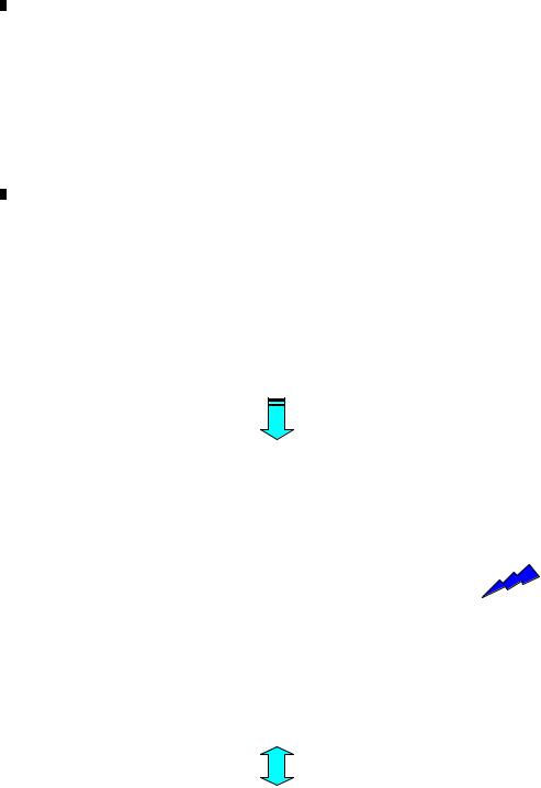
|
1 |
|
2 |
|
3 |
|
4 |
|
6. SERVICE MODE
6.1 CD TEST MODE
A
During pressing the "SOURCE" and "RPT" keys simultaneously, perform the reset-start, then turn ON the CD to enter the CDS test mode.
• How to issue the 1 - 6 keys in the 08 model's slave test:
The specification of the 08 model does not include the 1 - 6 keys issuance function for H/U and the remote control unit. Therefore, in order to issue commands in a slave test, use the direct FUNCTION keys alternatively to enable the equal key command sending function to the existing models.
Outline) Use the direct FUNCTION keys to display, select, or issue the KEY 1 - 6.
B |
<Direct FUNCTION keys and corresponding functions> |
|
|
|
Direct FUNCTION key |
Normal mode |
Slave test mode |
|
A |
COMP |
Selecting a key command |
|
B |
RDM |
Issuing a key command |
|
C |
RPT |
Switching a screen |
• For convenience, a name of each direct FUNCTION key is shown as "A", "B", and "C".
|
• How to issue the 1 - 6 keys for the CDS source: |
||
|
(The |
|
areas below are overwritten and displayed on character strings for the normal mode display.) |
C |
1 During the slave test mode, the key name "K1" is shown at the left by default. |
||
|
In this condition, press the A key to toggle K1 - K6, and select a command to be sent to the slave. |
||
|
|
C |
O M P A C T |
D I S C |
|
|
|
|
|
||
|
|
|
|
|
|
|
|
|
|
|
|
|
|
K |
1 |
! |
T - ! |
! |
! |
! |
! |
! |
|
|
|
|
|
FOLDER |
|
TRK |
|
MINUTE |
SECOND |
||
|
|
|
|
|
|
||||||
A key
•The one-line model shows only the bottom column.
|
C |
O M P A C T |
D I S C |
|
||
|
|
|
|
|
|
|
D |
K |
6 |
! |
T - ! |
! |
! ! ! ! |
2 During the K1 - K6 key names are displayed, press the B key and issue the selected command.
|
|
|
|
|
|
|
|
|
|
|
|
|
|
|
Send a key command selected |
|
|
C |
O |
M |
P |
A C |
T |
|
D |
I S C |
|
|
|
|
|
|
|
K |
1 |
|
! |
T |
- |
! |
! |
! |
! |
! |
! |
|
by pressing the KEY 1. |
E |
3 Press the |
C key to change display/non-display of key names. |
|
|
B key |
||||||||||
|
|
|
|||||||||||||
|
|
|
|
||||||||||||
|
When the non-display mode is selected for the K1 - K6 key names, |
|
"A key" and "B key" are invalid. |
||||||||||||
|
|
|
|
|
|
|
|
|
|
||||||
|
|
C O M P A C T |
|
D I S C |
|
|
|
|
|
||||||
|
|
|
|
|
|
|
|
|
|
|
|
|
|
|
|
|
|
K 1 |
|
! |
T |
- |
! |
! |
! |
! |
! |
! |
|
|
|
|
|
|
|
|
|
|
|
|
|
C key |
|
|
|
|
|
|
|
|
|
|
|
|
|
|
|
|
|
|
|
|
|
|
|
|
|
|
|
|
|
|
|
|
|
|
|
|
|
|
|
|
|
|
|
|
|
|
|
||||||
|
|
C O M P A C T |
|
D I S C |
|
|
|
|
|
||||||
|
|
|
|
|
|
|
|
|
|
|
|
|
|
|
• Pressing the A key or B key does not work. |
|
|
F |
- |
! |
! |
T |
- |
! |
! |
! |
! |
! |
! |
|
|
F
22 |
DEH-4090MP/XN/ID |
|
1 |
|
2 |
|
3 |
|
4 |
|
|
|
|
|
|
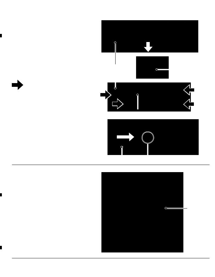
|
1 |
|
2 |
|
3 |
|
4 |
|
7. DISASSEMBLY
*NOTE) While the photograph shown is slightly different from this model in shape, the disassembly
A
procedure is the same.
- Removing the Keyboard Unit (Fig.1,2,3)
Pull arrow direction
and remove Detach Grille Assy.(Fig.1)
Fig.1
Remove the Knob Unit.(Fig.2)
B
|
|
|
Detach Grille Assy |
|
|
|
|
Knob Unit |
|||
|
|
|
|
|
|
|
|
|
|
||
|
|
|
|
|
|
|
|
|
|
||
|
|
|
|
|
|
|
|
|
|
Fig.2 |
|
|
|
1 Remove the four screws.(Fig.3) |
|
|
|
1 |
|
||||
|
|
Remove the Cover |
1 |
|
|
|
|||||
|
|
|
|
||||||||
|
|
|
|
|
|
|
|
|
|
||
|
|
|
|
|
|
|
|
||||
|
|
1 |
|
|
1 |
|
|||||
|
|
and then remove the Keyboard Unit. |
|
|
|
||||||
|
|
|
|
|
|
|
|
|
|
Fig.3 |
|
|
|
|
|
|
|
Cover |
|||||
C |
|
|
|
|
|
|
|
|
|
|
|
- Removing the Holder (Fig.4) |
|
|
|
|
|
|
|
|
|
||
|
|
|
|
|
|
|
|
|
|
|
|
|
|
Take off the pick of left and right |
|
|
|
|
|
|
|
|
|
|
|
and then a holder slide to the arrow course. |
|
|
|
|
|
|
|
|
|
|
|
|
|
|
|
|
|
|
|
Fig.4 |
|
|
|
|
|
|
|
|
|
|
|
||
|
|
|
|
|
|
|
|
|
|
||
|
|
|
|
|
|
|
|||||
|
|
|
|
|
|
|
|
|
|
|
|
|
|
|
|
|
|
|
|
|
|
|
|
Holder Pick
D
- Removing the Case and Panel (Fig.5)
Remove the Case and Panel.
Case
E
 Panel Fig.5
F
24 |
DEH-4090MP/XN/ID |
|
1 |
|
2 |
|
3 |
|
4 |
|
|
|
|
|
|

5  6
6  7
7  8
8
- Removing the CD Mechanism Module (Fig.6)
1 |
Remove the four screws. |
A |
|
1 |
|||
|
|
1
Disconnect the cable
and then remove the CD Mechanism Module.
|
1 |
|
|
|
|
|
|
|
|
||
|
1 |
|
|
B |
|
|
|
|
|||
|
|
|
|
|
|
|
|
Fig.6 |
|||
|
|
|
|
||
|
|
|
|
|
|
|
CD Mechanism Module |
|
|
||
|
|
|
|
|
|
- Removing the Panel AssyFig.7,8) |
|
|
|
|
|
1 |
1 |
C |
|||
1 Remove the two screws.(Fig.7) |
|
|
|||
|
Fig.7 |
||||
|
|
||||
Panel Assy
Push the place of the arrows
and then remove Panel Assy.(Fig.7,8)
D
Fig.8
- Removing the Panel Unit(Fig.9,10)
1 Remove the two screws.(Fig.9)
1 |
E |
|
|
|
1 |
|
Fig.9 |
Holder |
Panel Unit |
|||
Remove the Holder |
|
|
|
|
and then remove Panel Unit.(Fig.10) |
|
|
|
|
|
Fig.10 |
|||
|
|
|
||
|
|
|
||
|
|
|
||
|
|
|
|
F |
|
|
|
|
DEH-4090MP/XN/ID |
|
|
|
25 |
|
||
|
5 |
|
6 |
|
|
7 |
|
8 |
|
|
|
|
|
|
|
|
|
||||||
|
1 |
|
2 |
|
3 |
|
4 |
|
8.2 CHECKING THE GRATING AFTER CHANGING THE PICKUP UNIT
A

 Note :
The grating angle of the PU unit cannot be adjusted after the PU unit is changed.The PU unit in the CD mechanism module is adjusted on the production line to match the CD mechanism module and is thus the best adjusted PU unit for the CD mechanism module. Changing the PU unit is thus best considered as a last resort. However, if the PU unit must be changed, the grating should be checked using the procedure below.
 Purpose :
To check that the grating is within an acceptable range when the PU unit is changed.
B |
Symptoms of Mal-adjustment : |
If the grating is off by a large amount symptoms such as being unable to close tracking, being unable to perform track search operations, or taking a long time for track searching.
|
Method : |
|
|
Measuring Equipment |
Oscilloscope,Two L.P.F. |
|
Measuring Points |
E, F, REFO1 |
|
||
|
Disc |
TCD-782 |
|
||
|
Mode |
TEST MODE |
|
CD CORE UNIT(S10.5COMP2) |
|
|
C |
REFO1 |
|
|
|
|
|
|
E |
F |
L.P.F. |
|
|
|
|
|
|
E |
Xch |
Ych |
|
100 kohm |
|
|
|
|
Oscilloscope |
|
|
VREF |
390 pF |
|
|
|
|
|
|
F |
100 kohm |
|
|
VREF |
390 pF |
|
|
|
|
|
D |
|
L.P.F. |
|
 Checking Procedure
1.In test mode, load the disc and switch the 3 V regulator on.
2.Using the → and ← buttons, move the PU unit to the innermost track.
3.Press key 3 to close focus, the display should read "91". Press key 2 to implement the tracking balance adjustment the display should now read "81". Press key 3.The display will change, returning to "81" on the fourth press.
E4. As shown in the diagram above, monitor the LPF outputs using the oscilloscope and check that the phase difference is within 75 degrees. Refer to the photographs supplied to determine the phase angle.
5.If the phase difference is determined to be greater than 75 degrees try changing the PU unit to see if there is any improvement. If, after trying this a number of times, the grating angle does not become less than 75 degrees then the mechanism should be judged to be at fault.
 Note
Note
Because of eccentricity in the disc and a slight misalignment of the clamping center the grating waveform may be seen to "wobble" ( the phase difference changes as the disc rotates).The angle specified above indicates the average angle.
 Hint
Hint
Reloading the disc changes the clamp position and may decrease the "wobble".
F
30 |
DEH-4090MP/XN/ID |
|
1 |
|
2 |
|
3 |
|
4 |
|
|
|
|
|
|

5  6
6  7
7  8
8
Grating waveform |
Ech → Xch 20 mV/div, AC |
|
|
Fch → Ych 20 mV/div, AC |
|
|
A |
|
0 degrees |
30 degrees |
|
|
|
|
|
|
|
B
45 degrees |
60 degrees |
|
|
C
D
75 degrees |
90 degrees |
|
|
|
|
E
F
|
|
|
|
DEH-4090MP/XN/ID |
|
|
|
31 |
|
||
|
5 |
|
6 |
|
|
7 |
|
8 |
|
|
|
|
|
|
|
|
|
||||||
 Loading...