


 Loading...
ORDER NO.
CRT3174
DEH-1630R/XU/EW
HIGH POWER CD PLAYER WITH RDS TUNER
DEH-1630R XU/EW
DEH-1600R XU/EW
DEH-1600RB XU/EW
This service manual should be used together with the following manual(s):
Model No. |
Order No. |
Mech.Module |
|
|
Remarks |
||||
|
|
|
|
|
|
|
|
|
|
CX-3110 |
CRT3178 |
S10.1 |
CD Mech. Module : Circuit Description, Mech. Description, Disassembly |
||||||
|
|
|
|
|
|
|
|
|
|
|
|
|
|
|
|
|
|
|
|
|
|
|
|
|
|
|
|
|
|
|
|
|
|
|
|
|
|
|
|
|
|
|
|
|
|
|
|
|
|
|
|
|
|
|
|
|
|
|
|
For details, refer to "Important symbols for good services".
PIONEER CORPORATION 4-1, Meguro 1-chome, Meguro-ku, Tokyo 153-8654, Japan
PIONEER ELECTRONICS (USA) INC. P.O. Box 1760, Long Beach, CA 90801-1760, U.S.A.
PIONEER EUROPE NV Haven 1087, Keetberglaan 1, 9120 Melsele, Belgium
PIONEER ELECTRONICS ASIACENTRE PTE. LTD. 253 Alexandra Road, #04-01, Singapore 159936
 PIONEER CORPORATION 2003
K-ZZA. OCT. 2003 printed in Japan
1 |
2 |
3 |
4 |
SAFETY INFORMATION
This service manual is intended for qualified service technicians; it is not meant for the casual do-it-yourselfer.
AQualified technicians have the necessary test equipment and tools, and have been trained to properly and safely repair complex products such as those covered by this manual.
Improperly performed repairs can adversely affect the safety and reliability of the product and may void the warranty. If you are not qualified to perform the repair of this product properly and safely, you should not risk trying to do so and refer the repair to a qualified service technician.
1. Safety Precautions for those who Service this Unit.
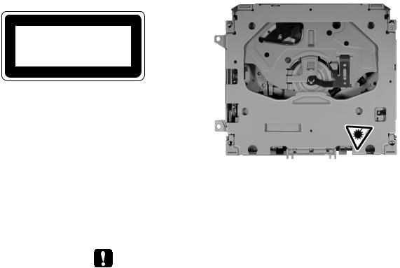
•When checking or adjusting the emitting power of the laser diode exercise caution in order to get safe, reliable results.
|
Caution: |
|
B |
1. |
During repair or tests, minimum distance of 13cm from the focus lens must be kept. |
2. |
During repair or tests, do not view laser beam for 10 seconds or longer. |
|
2.A “CLASS 1 LASER PRODUCT” label is affixed to the bottom of the player.
3.The triangular label is attached to the mechanism unit frame.
CLASS 1
LASER PRODUCT
C
D4. Specifications of Laser Diode
Specifications of laser radiation fields to which human access is possible during service. Wavelength = 800 nanometers
- CD Section Precaution
1. Before disassembling the unit, be sure to turn off the power. Unplugging and plugging the connectors during power-on mode may damage the ICs inside
E
the unit.
2. To protect the pickup unit from electrostatic discharge during servicing, take an appropriate treatment (shorting-solder) by referring to "the DISASSEMBLY" on page 44.
3. After replacing the pickup unit, be sure to check the grating. (See p.41.)
4. In this product, because the memory capacity of the microcomputer is insufficient, the test mode is not installed. However grating of the pickup unit can be confirmed.
F
2 |
|
DEH-1630R/XU/EW |
|
|
1 |
2 |
|
3 |
4 |
5 |
6 |
7 |
8 |
[ Important symbols for good services ]
In this manual, the symbols shown-below indicate that adjustments, settings or cleaning should be made securely. When you find the procedures bearing any of the symbols, be sure to fulfill them:
1. Product safety
You should conform to the regulations governing the product (safety, radio and noise, and other regulations), and should keep the safety during servicing by following the safety instructions described in this manual.
2. Adjustments
 To keep the original performances of the product, optimum adjustments or specification confirmation is indispensable. In accordance with the procedures or instructions described in this manual, adjustments should be performed.
3. Cleaning
For optical pickups, tape-deck heads, lenses and mirrors used in projection monitors, and other parts requiring cleaning, proper cleaning should be performed to restore their performances.
4. Shipping mode and shipping screws
To protect the product from damages or failures that may be caused during transit, the shipping mode should be set or the shipping screws should be installed before shipping out in accordance with this manual, if necessary.
5. Lubricants, glues, and replacement parts
Appropriately applying grease or glue can maintain the product performances. But improper lubrication or applying
 glue may lead to failures or troubles in the product. By following the instructions in this manual, be sure to apply the
 prescribed grease or glue to proper portions by the appropriate amount.For replacement parts or tools, the prescribed ones should be used.
|
|
|
|
|
|
|
|
|
|
|
|
|
|
|
|
|
|
|
|
|
|
|
|
|
|
|
|
|
|
|
|
|
|
DEH- |
1630R/XU/EW |
7 |
3 |
|
5 |
6 |
|
|
|
8 |
|||||||
A
B
C
D
E
F
1 2 3 4
CONTENTS
|
SAFETY INFORMATION..................................................................................................................................... |
2 |
|
A |
1. SPECIFICATIONS ............................................................................................................................................ |
5 |
|
2. EXPLODED VIEWS AND PARTS LIST |
6 |
||
|
|||
|
2.1 PACKING ................................................................................................................................................... |
6 |
|
|
2.2 EXTERIOR................................................................................................................................................. |
8 |
|
|
2.3 CD MECHANISM MODULE..................................................................................................................... |
12 |
|
|
3. BLOCK DIAGRAM AND SCHEMATIC DIAGRAM .......................................................................................... |
14 |
|
|
3.1 BLOCK DIAGRAM ................................................................................................................................... |
14 |
|
|
3.2 OVERALL CONNECTION DIAGRAM(GUIDE PAGE).............................................................................. |
16 |
|
|
3.3 KEYBOARD UNIT.................................................................................................................................... |
22 |
|
|
3.4 CD MECHANISM MODULE..................................................................................................................... |
24 |
|
|
4. PCB CONNECTION DIAGRAM ..................................................................................................................... |
28 |
|
|
4.1 TUNER AMP UNIT................................................................................................................................... |
28 |
|
B |
4.2 KEYBOARD UNIT.................................................................................................................................... |
32 |
|
4.3 CD MECHANISM MODULE |
34 |
||
|
|||
|
5. ELECTRICAL PARTS LIST ............................................................................................................................ |
36 |
|
|
6. ADJUSTMENT ............................................................................................................................................... |
40 |
|
|
6.1 CD ADJUSTMENT................................................................................................................................... |
40 |
|
|
6.2 CHECKING THE GRATING AFTER CHANGING THE PICKUP UNIT .................................................... |
41 |
|
|
6.3 ERROR MODE ........................................................................................................................................ |
43 |
|
|
7. GENERAL INFORMATION............................................................................................................................. |
44 |
|
|
7.1 DIAGNOSIS ............................................................................................................................................. |
44 |
|
|
7.1.1 DISASSEMBLY ..................................................................................................................................... |
44 |
|
|
7.1.2 CONNECTOR FUNCTION DESCRIPTION.......................................................................................... |
48 |
|
|
7.2 PARTS...................................................................................................................................................... |
49 |
|
C |
7.2.1 IC .......................................................................................................................................................... |
49 |
|
7.2.2 DISPLAY |
56 |
||
|
|||
|
7.3 OPERATIONAL FLOW CHART ............................................................................................................... |
58 |
|
|
7.4 CLEANING............................................................................................................................................... |
59 |
|
|
8. OPERATIONS ................................................................................................................................................ |
60 |
D
E
F
4 |
|
DEH-1630R/XU/EW |
|
|
1 |
2 |
|
3 |
4 |
5 |
6 |
7 |
8 |
1. SPECIFICATIONS
A
B
C
D
E
F
|
|
|
|
|
|
|
|
|
DEH- |
1630R/XU/EW |
7 |
5 |
|
5 |
6 |
|
|
|
8 |
|
1 2 3 4
|
2. EXPLODED VIEWS AND PARTS LIST |
|
NOTES : • Parts marked by " * " are generally unavailable because they are not in our Master Spare Parts List. |
A |
• Screw adjacent to"mark on the product are used for disassembly. |
|
• For the applying amount of lobricants or glue, follow the instructions in this manual. |
|
(In the case of no amount instructions,apply as you think it appropriate.) |
|
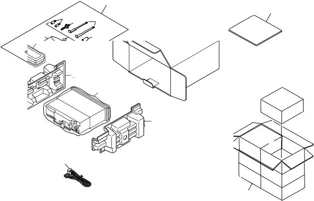
2.1 PACKING |
B
14
7
13 |
2 |
3 |
|
||
5 |
|
4 |
C
D
E |
(1) PACKING SECTION PARTS LIST |
|
|
|
|||
|
|
|
|
|
|
|
|
|
Mark No. |
Description |
Part No. |
Mark No. |
Description |
Part No. |
|
|
|
1 |
Cord Assy |
CDE7059 |
8 |
Carton |
See Contrast table(2) |
|
|
2 |
Screw |
CBA1650 |
9 |
Contain Box |
See Contrast table(2) |
|
|
3 |
Handle |
CNC5395 |
10 |
Protector |
CHP2663 |
|
|
4 |
Bush |
CNV3930 |
11 |
Protector |
CHP2664 |
|
* |
5 |
Polyethylene Bag |
CEG1160 |
12 |
Case Assy |
CXB3520 |
|
|
6 |
Polyethylene Bag |
CEG-162 |
13 |
Fixing Screw(M2x4) |
CBA1488 |
|
|
7-1 |
Owner's Manual |
YRD5001 |
14 |
Accessory Assy |
CEA3865 |
F |
|
7-2 |
Installation Manual |
YRD5006 |
|
|
|
* |
7-3 |
Passport |
CRY1013 |
|
|
|
|
|
|
|
|
||||
|
* |
7-4 |
Warranty Card |
CRY1157 |
|
|
|
6 |
|
DEH-1630R/XU/EW |
|
|
1 |
2 |
|
3 |
4 |

5 |
6 |
7 |
8 |
(2) CONTRAST TABLE
DEH-1630R/XU/EW, DEH-1600R/XU/EW and DEH-1600RB/XU/EW are constructed the same except for the following:
Mark |
NO |
Description |
DEH-1630R/XU/EW |
DEH-1600R/XU/EW |
DEH-1600RB/XU/EW |
|
|
|
|
|
|
|
8 |
Carton |
YHG5002 |
YHG5001 |
YHG5009 |
|
9 |
Contain Box |
YHL5002 |
YHL5001 |
YHL5009 |
|
|
|
|
|
|
- Owner's Manual, Installation Manual
Model |
Part No. |
Language |
|
DEH-1630R/XU/EW |
YRD5001 |
English, Spanish, German, French, Italian, Dutch |
|
DEH-1600R/XU/EW |
YRD5006 |
English, Spanish, German, French, Italian, Dutch |
|
DEH-1600RB/XU/EW |
|
|
|
A
B
C
D
E
F
|
|
|
|
|
|
|
|
|
DEH- |
1630R/XU/EW |
7 |
7 |
|
5 |
6 |
|
|
|
8 |
|

1 |
2 |
3 |
4 |
2.2 EXTERIOR
A
B
C
D
E
F
8 |
|
DEH-1630R/XU/EW |
|
|
1 |
2 |
|
3 |
4 |

|
5 |
6 |
(1) EXTERIOR SECTION PARTS LIST |
||
Mark No. |
Description |
Part No. |
1 |
Screw |
BSZ26P060FTC |
2 |
Screw |
BSZ30P060FTC |
3 |
Screw |
BSZ30P200FTC |
4 |
Cord Assy |
CDE7059 |
5 |
Cap |
CKX-003 |
6 |
Cable |
CDE7113 |
7 |
Case |
CNB2793 |
8 |
Holder |
CNC8659 |
9 |
Earth Plate |
CNC8915 |
10 |
Insulator |
CNM8059 |
11 |
Insulator |
CNM8174 |
12 |
Cushion |
CNM8890 |
13 |
Button |
CAC4836 |
14 |
Spring |
CBH1835 |
15 |
Spring |
CBH2208 |
16 |
Spring |
CBH2367 |
17 |
Bracket |
CNC6791 |
18 |
Holder |
CNC8042 |
19 |
Cover |
CNM6276 |
20 |
Arm |
CNV4692 |
21 |
Arm |
CNV4728 |
22 |
Arm |
CNV5576 |
23 |
Screw |
IMS20P030FZK |
24 |
Panel |
See Contrast table(2) |
25 |
CD Mechanism Module(S10.1) |
CXK5602 |
26 |
Screw |
ISS26P055FTC |
27 |
Tuner Amp Unit |
See Contrast table(2) |
28 |
Screw |
ASZ26P060FTC |
29 |
Screw |
BPZ26P080FTC |
30 |
Screw |
BSZ26P160FTC |
31 |
Fuse(10A) |
CEK1208 |
32 |
Pin Jack(CN352) |
CKB1057 |
33 |
Terminal(CN402) |
CKF1059 |
34 |
Plug(CN901) |
CKM1376 |
35 |
Connector(CN831) |
CKS3581 |
36 |
Connector(CN651) |
CKS3835 |
|
7 |
8 |
Mark No. |
Description |
Part No. |
37 |
Connector(CN621) |
CKS4124 |
38 |
Antenna Jack(CN401) |
CKX1056 |
39 |
Holder |
CND1328 |
40 |
Heat Sink |
CNR1668 |
41 |
FM/AM Tuner Unit |
CWE1645 |
42 |
Holder |
CND1054 |
43 |
Holder |
YNC5002 |
44 |
Detach Grille Assy |
See Contrast table(2) |
45 |
Screw |
BPZ20P100FZK |
46 |
Spring |
CBH2210 |
47 |
Button(CD EJECT) |
YAC5001 |
48 |
Button(TA, EQ) |
YAC5003 |
49 |
Button(UP) |
See Contrast table(2) |
50 |
Button(DOWN) |
See Contrast table(2) |
51 |
Button(SRC) |
YAC5011 |
52 |
Button(1-6) |
YAC5012 |
53 |
Button(LOUD) |
YAC5014 |
54 |
Button(UP, DOWN) |
See Contrast table(2) |
55 |
Button(LEFT, RIGHT) |
See Contrast table(2) |
56 |
Button(A, BAND) |
YAC5021 |
57 |
Button(DETACH) |
YAC5023 |
58 |
Cover |
See Contrast table(2) |
59 |
Keyboard Unit |
See Contrast table(2) |
60 |
LCD(LCD1801) |
See Contrast table(2) |
61 |
Connector(CN1801) |
CKS3580 |
62 |
Sheet |
CNM7932 |
63 |
Lens |
CNV7060 |
64 |
Connector |
CNV7369 |
65 |
Holder |
YNC5001 |
66 |
Lighting Conductor |
YNV5001 |
67 |
Rubber |
YNV5003 |
68 |
Grille Unit |
See Contrast table(2) |
69 |
Chassis Unit |
See Contrast table(2) |
70 |
Transistor(Q911, 921, 991) |
2SD2396 |
71 |
IC(IC302) |
TDA7386 |
72 |
Sheet |
See Contrast table(2) |
A
B
C
D
E
F
|
|
|
|
|
|
|
|
|
DEH- |
1630R/XU/EW |
7 |
9 |
|
5 |
6 |
|
|
|
8 |
|
1 |
2 |
3 |
4 |
(2) CONTRAST TABLE
DEH-1630R/XU/EW, DEH-1600R/XU/EW and DEH-1600RB/XU/EW are constructed the same except for the following:
A |
|
|
|
|
|
|
|
Mark |
NO |
Description |
DEH-1630R/XU/EW |
DEH-1600R/XU/EW |
DEH-1600RB/XU/EW |
||
|
|||||||
|
|
|
|
|
|
|
|
|
|
24 |
Panel |
YNS5031 |
YNS5032 |
YNS5031 |
|
|
|
27 |
Tuner Amp Unit |
YWM5007 |
YWM5001 |
YWM5019 |
|
|
|
44 |
Detach Grille Assy |
YXA5026 |
YXA5014 |
YXA5032 |
|
|
|
49 |
Button(UP) |
YAC5007 |
YAC5005 |
YAC5007 |
|
|
|
50 |
Button(DOWN) |
YAC5010 |
YAC5008 |
YAC5010 |
|
|
|
54 |
Button(UP, DOWN) |
YAC5017 |
YAC5015 |
YAC5017 |
|
|
|
55 |
Button(LEFT, RIGHT) |
YAC5020 |
YAC5018 |
YAC5020 |
|
|
|
58 |
Cover |
YNS5020 |
YNS5021 |
YNS5020 |
|
B |
|
59 |
Keyboard Unit |
YWM5008 |
YWM5002 |
YWM5020 |
|
|
|
60 |
LCD(LCD1801) |
CAW1779 |
CAW1731 |
YAW5006 |
|
|
|
68 |
Grille Unit |
YXA5002 |
YXA5001 |
YXA5013 |
|
|
|
69 |
Chassis Unit |
YXA5036 |
YXA5035 |
YXA5037 |
|
|
|
72 |
Sheet |
Not used |
Not used |
CNM7881 |
|
|
|
|
|
|
|
|
C
D
E
F
10 |
|
DEH-1630R/XU/EW |
|
|
1 |
2 |
|
3 |
4 |
5 |
6 |
7 |
8 |
A
B
C
D
E
F
|
|
|
|
|
|
|
|
|
DEH- |
1630R/XU/EW |
7 |
11 |
|
5 |
6 |
|
|
|
8 |
|
1 2 3 4
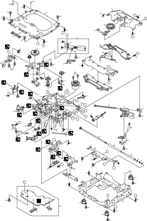
2.3 CD MECHANISM MODULE
 5 42
5 42 
A |
13 |
|
|
|
81 |
|
|
|
|
|
|
5 |
|
34 |
|
15 |
22 |
|
|
|
|
||
|
|
|
|
|
|
|
|
|
5 |
|
E |
13 |
|
|
|
F |
|
|
|
|
|
||
|
|
|
|
93 |
|
|
|
|
|
|
A |
13 |
|
92 |
|
|
|
|
|
|
|
|
|
||
|
|
|
|
|
B |
|
|
|
|
|
|
44 |
|
|
|
82 |
|
|
|
|
|
|
|
|
|
|
|
|
|
|
|
5 |
C |
13 |
86 |
|
83 |
68 |
|
|
|
|
D |
|
|
|
|||
B |
1 |
54 |
52 |
|
|
|
|
|
|
|
|
|
|
|
|
||||
|
|
|
53 |
|
86 |
|
|
28 |
I |
|
|
|
|
|
|
|
|||
|
|
|
|
|
|
|
|
|
|
|
|
37 |
|
|
|
|
|
4 |
|
|
|
|
|
|
|
|
|
|
|
|
|
|
|
4 |
71 |
|
23 |
|
45 |
|
|
|
|
1 |
|
|
|
J |
|
|
55 |
|
|
|
|
|
|
||
|
|
|
|
|
|
|
|
||
|
4 |
36 |
|
|
|
87 |
38 |
|
|
|
|
|
|
50 |
|
||||
|
|
4 |
73 |
|
|
|
|
||
|
|
|
|
|
|
|
|
||
|
|
|
1 |
|
|
|
|
|
|
18 |
29 |
72 |
K |
2 |
51 |
10 |
75 |
64 |
C |
47 |
|
|
|
|
1 |
|
|
|
|
|
|
I |
|
|
|
|
||
|
|
2 |
|
|
76 |
B |
|
59 |
|
24 |
|
1 |
|
|
|
|
|
|
49 |
|
|
7 |
|
|
|
|
|
|
|
|
|
61 |
|
|
|
|
|
E |
|
|
|
|
|
|
|
|
|
77 |
|
|
|
|
|
|
|
|
|
|
|
|
|
2 |
|
M |
|
1 |
|
F |
|
|
|
|
|
|
|
||||
|
|
|
|
|
|
|
|||
|
63 |
|
|
|
|
|
|
A |
Q |
|
|
1 |
|
|
|
|
|
27 |
|
|
2 |
|
|
|
|
|
|
H |
|
|
|
|
|
|
|
G |
|
||
|
21 |
|
L |
|
|
|
J |
67 |
|
|
M |
|
|
|
|
|
|
||
|
|
1 |
N |
|
|
|
|
|
|
|
|
57 |
O |
D |
|
|
|
||
|
|
|
|
|
|
||||
|
|
|
R |
16 |
|
|
|
||
|
|
|
|
|
12 |
|
|
||
D |
79 |
|
|
|
|
|
|
||
|
|
|
|
|
|
|
|||
58 |
|
1 |
|
|
|
|
|
||
|
|
|
|
|
3 |
|
78 |
||
|
|
|
|
|
|
|
|
||
|
|
|
|
|
|
|
|
|
|
|
|
|
|
1 |
|
|
33 |
|
|
|
|
|
|
|
P |
|
|
|
|
|
2 |
62 |
|
|
|
20 |
|
|
|
|
|
|
2 |
|
|
|
|
||
80
1 |
40 |
1 |
|
N |
|
|
|
1GEM1024 |
|
1 |
39 |
|
|
2GEM1045 |
|
|
|
|
|
|
|
1 |
69 |
25 |
|
3GEM1035 |
|
P |
|
L |
|
|
|
|
|
||
|
56 |
19 |
30 |
|
70 |
|
|
|
|
||
E |
|
|
|
14 |
|
|
|
|
|
||
|
|
|
41 |
|
|
R
31
C
91 |
C |
65 |
|
||
|
|
|
|
|
1 |
|
|
85 |
F |
3 |
2 |
|
66 |
12 |
|
DEH-1630R/XU/EW |
|
1 |
2 |
|
3 |
23
90
60
 43
43
K
35
O
31
85
26
G
H
28
48
8
17
46
6
60
11 89
10
74
85
Q
14
4

5 6 7 8
CD MECHANISM MODULE SECTION PARTS LIST
Mark No. |
Description |
Part No. |
|
Mark No. |
|
Description |
Part No. |
||
1 |
CD Core Unit(S10.1) |
CWX2947 |
|
|
|
|
|
|
|
2 |
Connector(CN101) |
CKS4182 |
51 |
Gear |
CNV7208 |
||||
3 |
Connector(CN701) |
CKS4188 |
52 |
Gear |
CNV7209 |
||||
4 |
Screw |
BMZ20P035FTC |
53 |
Gear |
CNV7210 |
||||
5 |
Screw |
BSZ20P040FTC |
54 |
Gear |
CNV7211 |
||||
|
|
|
|
55 |
Gear |
CNV7212 |
|||
6 |
Screw(M2x4) |
CBA1362 |
|
|
|
|
|
|
|
7 |
Screw(M2x3) |
CBA1511 |
56 |
Rack |
CNV7214 |
||||
8 |
Screw(M2x3) |
CBA1527 |
57 |
Arm |
CNV7215 |
||||
9 |
••••• |
|
|
58 |
Arm |
CNV7216 |
|||
10 |
Washer |
CBF1038 |
59 |
Guide |
CNV7217 |
||||
|
|
|
|
60 |
Roller |
CNV7218 |
|||
11 |
Washer |
CBF1060 |
|
|
|
|
|
|
|
12 |
Spring |
CBH2390 |
61 |
Gear |
CNV7219 |
||||
13 |
Spring |
CBH2606 |
62 |
Arm |
CNV7221 |
||||
14 |
Spring |
CBH2607 |
63 |
Arm |
CNV7220 |
||||
15 |
Spring |
CBH2608 |
64 |
Arm |
CNV7222 |
||||
|
|
|
|
65 |
Damper |
CNV7313 |
|||
16 |
Spring |
CBH2609 |
|
|
|
|
|
|
|
17 |
Spring |
CBH2610 |
66 |
Damper |
CNV7314 |
||||
18 |
Spring |
CBH2735 |
67 |
Arm |
CNV7341 |
||||
19 |
Spring |
CBH2612 |
68 |
Arm |
CNV7342 |
||||
20 |
Spring |
CBH2613 |
69 |
Guide |
CNV7360 |
||||
|
|
|
|
70 |
Guide |
CNV7361 |
|||
21 |
Spring |
CBH2614 |
|
|
|
|
|
|
|
22 |
Spring |
CBH2615 |
71 |
Holder |
CNV7437 |
||||
23 |
Spring |
CBH2616 |
72 |
Arm |
CNV7805 |
||||
24 |
Spring |
CBH2617 |
73 |
Gear |
CNV7595 |
||||
25 |
Spring |
CBH2620 |
74 |
Damper |
CNV7618 |
||||
|
|
|
|
75 |
Motor Unit(M1) |
CXB6007 |
|||
26 |
Spring |
CBH2621 |
|
|
|
|
|
|
|
27 |
Spring |
CBH2641 |
76 |
Chassis Unit |
CXC2318 |
||||
28 |
Spring |
CBH2642 |
77 |
Screw Unit |
CXB8729 |
||||
29 |
Spring |
CBH2643 |
78 |
Gear Unit |
CXC2397 |
||||
30 |
Spring |
CBH2659 |
79 |
Arm Unit |
CXC2316 |
||||
|
|
|
|
80 |
Arm |
CND1896 |
|||
31 |
Spring |
CBH2688 |
|
|
|
|
|
|
|
32 |
••••• |
|
|
81 |
Arm |
CND1894 |
|||
33 |
Shaft |
CLA4441 |
82 |
Motor Unit(M2) |
CXB8933 |
||||
34 |
Frame |
CNC9962 |
83 |
Bracket |
CNC9985 |
||||
35 |
Frame |
CNC9963 |
84 |
••••• |
|
||||
|
|
|
|
85 |
Screw(M2x5) |
EBA1028 |
|||
36 |
Bracket |
CNC9966 |
|
|
|
|
|
|
|
37 |
Bracket |
CND1895 |
86 |
Screw |
JFZ20P020FTC |
||||
38 |
Arm |
CNC9968 |
87 |
Screw |
JGZ17P022FTC |
||||
39 |
Arm |
CND1909 |
88 |
••••• |
|
||||
40 |
Lever |
CND2032 |
89 |
Washer |
YE20FTC |
||||
|
|
|
|
90 |
Pickup Unit(P10)(Service) |
CXX1647 |
|||
41 |
Lever |
CNC9984 |
|
|
|
|
|
|
|
42 |
Sheet |
CNM8134 |
91 |
Screw |
IMS26P030FTC |
||||
43 |
Collar |
CNV7798 |
92 |
Spring |
CBL1635 |
||||
44 |
Guide |
CNV7799 |
93 |
Clamper |
CNV7197 |
||||
45 |
Arm |
CNV7800 |
|
|
|
|
|
|
|
46 |
Rack |
CNV7199 |
|
|
|
|
|
|
|
47 |
Holder |
CNV7201 |
|
|
|
|
|
|
|
48 |
Holder |
CNV7202 |
|
|
|
|
|
|
|
49 |
Arm |
CNV7203 |
|
|
|
|
|
|
|
50 |
Gear |
CNV7207 |
|
|
|
|
|
|
|
|
|
|
|
|
|
|
|
|
|
|
|
|
|
DEH- |
1630R/XU/EW |
|
7 |
13 |
|
|
5 |
6 |
|
|
|
|
|
8 |
|
A
B
C
D
E
F

1 |
2 |
3 |
4 |
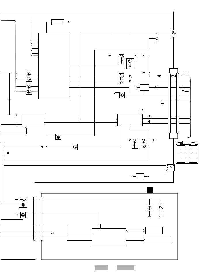
3. BLOCK DIAGRAM AND SCHEMATIC DIAGRAM
3.1 BLOCK DIAGRAM
A
A TUNER AMP UNIT
|
|
|
|
|
|
|
|
|
|
|
|
|
|
|
|
|
|
VDD |
|
|
|
|
|
|
|
|
|
|
|
|
|
|
|
|
|
|
|
|
|
|
FM/AM TUNER UNIT |
|
|
7 |
6 |
|
|
|
13 |
5 |
10 |
9 |
8 |
11 |
14 |
18 |
19 |
20 |
21 |
|
|
|
|
|
|
|
|
|
|||||
|
|
|
|
|
|
WC |
CE2 |
|
|
ROM VDD |
SL |
DI |
CK |
CE1 |
LDET |
DO |
RDS CK |
RDS DATA |
RDS LOCK |
RDS HSLK |
|
|
|
|
|
|
|
|
|
|||||||
|
|
|
|
|
|
|
|
|
|
|
|
|
|
|
|
|
|
|
|
|
|
|
||||||||||||||
B |
|
|
|
|
|
|
|
|
|
|
|
IC 3 EEPROM |
|
|
|
|
IC 5 |
|
|
|
|
|
|
|
|
|
|
|
|
|
|
|
|
|||
|
|
|
|
|
|
|
|
|
|
|
|
5.0V |
|
|
|
|
|
5V |
← 3.3V |
|
|
|
|
|
|
|
|
|
|
|
|
|
|
|
||
|
|
|
|
|
|
|
|
|
|
|
|
|
OSC |
|
|
LPF |
|
|
|
|
|
|
|
|
|
|
|
|
|
|
|
|
|
|
|
|
|
ANTENNA |
CN401 |
|
AM ANT |
|
FMRF |
|
|
|
|
|
|
|
|
|
|
|
|
|
|
|
|
|
|
|
|
|
|
|
|
|
|
|
|
|
|
|
|
1 |
|
|
|
|
|
|
|
|
|
|
|
|
|
|
|
|
|
|
|
|
|
|
|
|
|
|
|
|
|
|
|
|||
|
|
1 |
|
ATT |
|
|
|
|
|
|
|
|
|
|
|
|
|
|
|
|
|
|
|
|
|
|
|
|
|
|
|
|
|
|
|
|
|
|
|
|
|
|
|
|
|
|
|
|
|
|
|
|
|
|
|
|
|
|
|
|
|
|
|
|
|
|
|
|
|
|
|
||
|
|
2 |
|
|
|
|
|
|
|
|
|
|
|
|
|
|
|
|
|
|
|
|
|
|
|
|
|
|
|
Rch 24 |
|
|
|
|
|
|
|
|
|
|
|
|
|
|
|
|
|
|
|
|
|
|
|
|
|
|
|
|
|
|
|
|
|
|
IC 2 |
|
|
|
|
|
|
|
|
|
|
|
|
FM ANT |
|
|
|
|
|
|
|
|
IC 1 |
|
|
|
|
|
|
|
|
|
|
|
|
|
2.5V |
|
|
|
|
|
|
|
|
|
|
|
|
|
|
|
|
|
|
|
|
|
|
|
|
|
|
|
|
|
|
|
|
|
|
|
|
|
|
|
|
|
|
|
|||
|
|
|
|
|
|
|
|
|
|
|
|
3.3V |
|
|
|
|
|
|
|
|
|
|
|
|
|
|
|
|
|
|
|
|
|
|
||
|
|
|
3 |
|
ATT |
|
|
|
|
|
|
|
|
|
|
|
|
|
|
|
|
|
|
|
|
|
|
|
Lch 23 |
|
|
|
|
RDS_DA |
||
|
|
|
|
|
FMRF |
|
|
|
|
|
MIXER, IF AMP |
|
|
|
|
|
|
|
|
|
|
|
|
|
|
|
|
|
||||||||
|
|
|
|
|
|
|
|
|
|
|
|
|
|
|
|
|
|
|
|
|
|
DET, FM MPX, |
|
|
|
|
|
|
|
|
||||||
|
|
|
|
|
|
|
|
|
|
|
|
|
|
|
|
|
|
|
|
|
|
|
|
|
|
|
|
|
|
|
|
|
|
|
||
|
|
|
|
|
|
|
RF adj |
|
|
|
|
|
|
|
|
|
|
|
|
|
|
|
|
|
|
|
RDS DECODER |
|
|
|
|
|
|
|
RDS_CK |
|
|
|
|
|
|
|
|
|
|
|
|
|
|
|
|
|
|
|
|
|
|
|
|
|
|
|
|
|
|
|
|
|
|
|
|
||
|
|
|
|
|
ANT adj |
|
|
|
|
|
|
|
|
|
|
|
|
|
|
|
|
|
|
|
|
|
|
|
|
|
|
|
|
|
||
|
|
|
|
|
|
|
|
|
|
|
|
|
|
|
|
|
|
|
|
|
|
|
|
|
|
|
|
|
|
|
|
|
|
|
|
RDS_HS |
|
|
|
|
|
|
|
|
|
|
|
|
|
|
T51 |
CF52 |
|
|
|
|
|
|
|
|
|
|
|
|
|
|
|
|
|
|
RDS_LO |
||
|
|
|
|
|
|
|
|
|
|
|
|
|
|
|
|
|
|
CF51 |
|
|
|
|
|
|
|
|
|
|
|
|
|
|
|
|
|
|
|
|
|
|
|
|
|
|
|
|
|
|
|
|
|
|
|
|
|
|
|
|
|
|
|
|
|
|
|
|
|
|
|
|
|
|
|
C |
|
|
|
|
|
|
|
|
|
|
|
|
AUDIOGND |
|
|
|
|
|
|
|
|
|
|
|
|
|
|
|
|
|
|
|
|
|
|
|
|
|
|
|
|
|
|
|
|
|
RFGND |
OSCGND |
DGND |
|
|
|
VDD 3.3 |
|
|
IC 4 |
|
|
|
|
|
|
|
|
|
|
|
|
|
|
|
||
|
|
|
|
|
|
|
|
|
|
NC |
VCC |
3.3V |
3.3V |
← 2.5V |
2.5V |
|
|
|
|
|
|
|
|
|
|
|
|
|
|
|||||||
|
|
|
|
|
|
|
|
|
|
|
|
|
|
|
|
|
|
|
|
|
|
|
|
|
|
|
|
|
||||||||
|
|
|
|
|
|
|
|
|
|
2 |
12 |
15 |
22 |
16 |
|
4 |
17 |
|
|
|
|
|
|
|
|
|
|
|
|
|
|
|
|
|
|
|
|
|
|
|
|
|
|
|
|
|
|
|
|
|
|
|
|
|
TUN 3V |
|
|
|
|
|
|
|
|
|
|
|
|
|
|
|
TUN L |
2 |
|
|
|
|
|
|
|
|
|
|
|
|
|
|
|
|
|
|
|
VCC |
|
|
|
|
|
|
|
|
|
|
|
|
|
|
|
|
|
|
|
|
|
|
|
|
|
|
|
|
|
|
|
|
|
|
|
|
|
|
|
|
|
|
|
|
|
|
|
|
|
|
|
|
|
CD L |
3 |
|
PICKUP UNIT |
|
|
CD CD CORE UNIT(S10.1) |
|
|
|
|
|
|
|
|
|
|
|
|
|
|
|
|
|
|
|
|
mute |
48 |
|
|||||||||
D |
(SERVICE)(P10) |
|
|
|
|
|
|
|
|
|
|
|
|
|
|
|
|
|
|
|
|
|
|
|||||||||||||
|
|
|
|
|
|
|
|
|
|
|
|
|
|
|
|
|
|
|
|
|
|
70 |
|
|||||||||||||
|
|
|
|
|
|
|
CN101 |
|
|
|
|
|
|
|
|
|
|
|
|
|
|
CN701 |
|
|
|
|
|
|
|
|
|
|
|
X1 |
|
|
|
LASER |
|
|
|
|
|
|
|
|
|
|
|
|
|
|
|
|
|
|
|
|
CN651 |
|
|
|
|
|
|
|
|
X601 |
|
||||
|
|
|
|
|
|
Q101 |
|
|
|
|
|
|
|
|
|
|
|
|
|
|
|
|
|
|
|
|
|
|
|
|
||||||
|
|
|
LD+ |
|
|
|
|
|
|
|
|
|
|
1 |
|
|
|
20 |
|
LOUT |
|
|
|
|
|
|
|
|
X2 |
69 |
|
|||||
|
DIODE |
|
|
|
14 |
|
3R3V |
|
|
|
|
|
|
LD |
LOUT |
|
8 |
14 |
|
|
|
|
|
|
|
|
|
|
||||||||
|
|
|
|
|
|
|
|
|
|
|
|
|
|
|
|
|
|
|
|
|
|
|
|
|
|
|
|
|
||||||||
|
|
|
|
MD |
|
5 |
|
|
|
|
|
|
|
|
|
2 |
PD |
|
xtal |
23 |
|
|
|
|
|
|
|
|
|
|
|
|
|
SYSPW |
43 |
|
|
|
|
|
|
|
|
|
|
|
|
|
|
|
|
|
|
|
|
|
|
|
|
|
|
|
|
|
|
|
|
|
|
|
|
|
|
|
|
HOLOGRAM |
|
|
|
|
|
|
|
|
AC, F, E, BD |
|
|
|
|
|
|
X201 |
|
|
|
|
|
|
SYSTEM CONTROLLER |
80 |
|
|||||||||
|
|
|
|
|
|
|
|
|
|
|
|
|
|
|
|
|
|
|
|
|
|
|
|
|
|
|
STRKEY1 |
|
||||||||
|
|
|
|
|
|
|
|
|
|
|
|
|
|
|
SERVO XTAL |
24 |
|
|
|
|
|
|
|
|
|
|
|
|
|
|
||||||
|
|
UNIT |
|
|
|
|
|
|
|
|
|
|
|
|
|
|
|
|
|
|
|
|
|
|
|
|
|
|
|
|
KEY2 |
46 |
|
|||
|
|
|
|
|
|
|
|
|
|
|
|
|
|
|
|
|
|
|
|
|
|
|
|
|
|
|
|
|
|
|
|
|||||
|
|
|
|
FOP |
|
|
FOP |
|
|
|
|
|
|
|
|
|
CONTROL, |
|
|
|
|
|
|
|
|
|
|
|
|
|
|
|
|
|
|
|
|
|
FOCUS ACT. |
|
1 |
|
|
|
|
|
|
|
|
|
DSP, |
|
|
|
|
|
|
|
|
|
|
|
|
|
|
|
|
|
|
||||
|
|
TOP |
|
TOP |
|
|
|
|
|
|
|
|
|
|
|
|
|
|
|
|
|
|
|
|
|
|
|
|
|
|
|
|||||
|
MONITOR TRACKING ACT. |
|
4 |
|
|
|
|
|
|
|
|
|
LPF, DAC |
|
|
|
|
|
|
|
|
|
|
|
|
IC 601(2/2) |
|
|
|
|||||||
|
|
|
|
|
|
|
|
|
|
|
|
|
|
|
|
|
|
|
|
IC 652 |
|
|
|
|
|
|
||||||||||
|
DIODE |
|
|
|
|
|
|
|
|
|
|
|
|
|
|
|
|
|
|
|
|
|
|
|
|
|
|
PE5329B |
|
|
|
|||||
|
|
|
|
|
|
|
|
|
12 |
|
|
|
FD, TD, SD, MD |
IC 201 |
SO |
12 |
XSI |
16 |
6 |
2 |
4 |
16 |
XSI |
|
|
|
|
|
|
|
||||||
|
|
|
|
|
|
|
|
|
FOP |
|
|
|
|
|
|
UPD63712AGC |
|
|
|
|
|
|
|
|
29 |
LOEJ |
|
|
|
|
|
|
|
|||
|
|
|
|
|
|
|
|
|
13 |
TOP |
|
|
|
|
|
42 |
LIMIT |
|
|
|
|
|
|
|
|
TC7SET08FU |
28 |
|
|
|
|
|
|
|
||
|
|
|
|
|
|
|
|
|
|
ACT,MOTOR |
|
|
|
|
|
|
|
|
|
|
|
|
|
|
|
79 |
CONT |
|
|
|
|
|
|
|
||
|
|
SPINDLE |
M |
|
|
|
|
|
|
|
|
|
|
|
|
|
|
|
|
|
|
|
|
|
DSCSNS |
|
|
|
|
|
|
|
||||
|
|
|
|
|
|
|
|
DRIVER |
|
|
|
|
|
|
|
|
|
|
|
|
|
|
|
|
|
|
|
|
|
|
|
|||||
|
|
MOTOR |
|
|
|
|
|
|
HOME |
|
|
|
|
|
|
|
|
|
|
|
|
|
CLMP 27 |
|
|
|
|
|
|
|
||||||
|
|
|
|
|
|
|
16 |
|
|
|
|
|
|
|
|
|
|
|
|
|
CLAMPSW |
|
|
|
|
|
|
|||||||||
|
|
|
|
|
|
|
|
|
SOP |
|
|
|
|
|
|
|
|
|
|
|
|
|
|
|
|
|
|
|
|
|
||||||
|
|
|
|
|
|
|
|
|
|
|
|
|
|
|
|
|
|
|
|
|
|
|
|
|
|
78 |
|
|
|
|
|
|
||||
|
|
|
|
|
|
|
|
|
15 |
SOM |
|
|
|
|
|
|
|
|
|
|
|
|
|
|
|
|
|
VDSENS |
|
|
|
|
|
|
|
|
|
|
|
|
|
|
|
|
|
|
|
|
|
|
|
|
|
|
|
|
|
|
|
|
|
|
|
|
|
|
|
|
|
|
|||
|
LOADING/ CARRIAGEMOTOR |
M |
|
|
|
|
|
17 |
LCOM |
|
|
|
|
|
|
|
|
|
|
|
|
|
|
|
|
|
|
|
|
|
|
|
|
|
|
|
|
|
|
|
|
|
18 |
|
LOEJ |
22 |
|
|
|
|
|
|
|
|
LOEJ |
5 |
17 |
|
|
|
|
VDCONT |
|
|
|
|
|
|
|
||||
|
|
|
|
|
|
|
|
|
|
LCOP |
|
|
|
|
|
|
|
|
|
|
|
|
|
|
|
KYDT |
dsens |
DPDT |
swvdd |
ILMPW |
|
|
||||
E |
|
|
|
|
|
|
|
|
|
|
|
CONT |
9 |
|
|
|
|
|
|
|
|
CONT |
7 |
15 |
|
|
|
|
B.UP |
|
||||||
|
|
|
|
|
|
|
|
|
|
|
|
|
|
|
|
|
|
|
|
|
|
|
|
|
|
|
|
|
|
|
|
|
|
|
|
|
|
|
|
|
|
|
|
|
|
|
IC 301 |
|
|
|
|
|
|
|
|
|
|
|
|
|
|
|
|
41 |
8 |
65 |
9 |
21 |
22 |
|
|
||
|
|
|
|
|
|
|
|
|
|
|
|
|
|
|
|
|
|
|
|
|
|
|
|
|
|
|
|
|
|
|
|
|
|
|||
|
|
|
|
|
|
|
|
|
|
BA5996FP |
|
|
|
|
|
|
|
|
|
|
|
|
|
|
|
|
|
|
|
|
|
|
|
|
||
|
|
|
|
|
|
|
|
|
|
|
|
|
|
|
|
|
|
|
|
|
|
DSCSNS |
6 |
16 |
|
|
|
|
|
|
|
|
|
|
|
|
|
|
|
|
|
|
|
|
|
|
|
|
|
|
|
|
|
|
|
|
|
|
CLMP |
|
|
|
|
|
|
|
|
|
|
|
|
|
Q |
|
|
|
|
|
|
|
|
|
|
|
|
|
|
|
|
|
|
|
|
|
|
11 |
11 |
|
|
|
|
|
|
|
|
|
|
VDD |
|
|
|
|
|
|
|
|
|
|
|
|
|
|
|
|
|
|
|
|
|
|
|
|
|
|
VDSENS |
|
|
|
|
|
|
|
|
|
|||
|
|
|
|
|
|
|
|
|
|
|
|
|
|
|
|
|
|
|
|
|
|
VD |
|
Q991 |
|
|
|
|
|
|
|
|
|
|||
|
|
|
|
|
|
|
|
|
|
|
|
|
|
|
|
|
|
|
|
|
|
|
|
|
|
|
|
|
|
|
|
|
|
|
||
|
|
|
|
|
|
|
|
|
|
|
|
|
|
|
|
CLAMP |
|
|
|
|
1 |
20 |
|
|
|
|
|
|
|
|
|
|
|
|
||
|
|
|
|
|
|
|
|
|
|
|
|
|
|
|
|
|
|
|
VD |
|
|
|
B.UP |
|
|
|
|
|
|
|
|
|||||
|
|
|
|
|
|
|
12EJ |
8EJ |
DSCSNS |
|
|
|
|
|
|
|
3.3V REGULATOR |
2 |
21 |
|
|
|
|
|
|
|
|
|
|
|
|
|||||
|
|
|
|
|
|
|
|
|
|
|
|
|
|
|
|
|
|
|
|
|
|
|
|
|
|
|
|
|
|
|
|
|||||
|
|
|
|
|
|
|
|
|
|
|
|
|
|
|
|
|
3R3V |
3 |
IC 701 |
1 |
|
|
|
|
|
|
|
|
|
|
|
|
|
|
||
|
|
|
|
|
|
|
|
|
|
|
|
|
|
|
|
|
|
|
|
|
|
|
Q992 |
|
|
|
|
|
|
|
|
|
||||
|
|
|
|
|
|
|
|
|
|
|
|
|
|
|
|
|
|
|
|
|
|
|
|
|
|
|
|
|
|
|
|
|
||||
|
|
|
|
|
|
|
|
|
|
|
|
|
|
|
|
|
|
|
|
|
|
|
|
|
|
|
|
|
|
|
|
|
|
|
|
|
|
|
|
|
|
|
|
|
|
|
|
|
|
|
|
|
|
|
NJM2391DL1-33 |
|
|
|
|
|
|
|
|
|
|
|
|
|
|
||||
F |
|
|
|
|
|
|
|
|
|
|
|
|
|
|
|
|
|
|
|
|
|
|
|
|
|
|
|
|
|
|
|
|
|
|
|
|
|
14 |
1 |
|
|
|
|
|
|
|
2 |
|
DEH-1630R/XU/EW |
|
3 |
|
|
|
|
|
|
|
4 |
|
|
|
|
|
|||||||||
|
|
|
|
|
|
|
|
|
|
|
|
|
|
|
|
|
|
|
|
|
|
|
|
|
|
|
|
|
|
|
|
|||||
|
|
|
|
|
5 |
|
|
|
|
6 |
|
|
|
|
|
7 |
|
|
|
|
|
8 |
|
|
|
|
|
|
|
|
|
|
|
|
|
|
|
|
|
|
|
|
|
|
|
|
|
|
A |
|
|
|
|
|
|
|
|
RESET |
|
|
|
|
|
|
|
|
|
|
|
|
|
|
|
|
|
|
|
|
|
|
|
1 |
IC 961 |
2 |
VDD |
|
|
|
|
|
|
|
|
|
|
|
|
|
|
|
|
|
|
|
|
|
|
S-80834CNY |
|
|
|
|
|
|
|
|
|
|
|
|
|
|
||
|
|
|
|
|
|
|
|
|
|
|
|
|
|
|
|
|
|
|
|
|
|
|
||
|
|
|
|
|
|
|
|
|
|
|
|
|
|
|
|
|
|
|
CN352 |
PRE OUT |
|
|
||
|
|
|
|
|
|
|
60 |
|
|
|
|
|
|
|
|
|
RL |
|
2 |
|
RL |
|
|
|
|
|
|
|
|
|
|
reset |
|
|
|
|
|
|
|
|
|
|
|
|
|
|
|
|
|
|
|
|
|
|
|
|
|
|
|
|
|
|
|
|
|
|
Q352 |
|
|
|
|
|
|
|
|
|
|
|
|
|
|
|
|
|
|
|
|
|
|
|
|
|
|
|
|
|
|
|
|
|
|
|
CE2 |
55 |
TUNPCE2 |
|
|
|
|
|
|
|
|
|
|
|
|
|
|
|
|
|
||
|
|
|
CE1 |
56 |
TUNPCE1 |
|
|
|
|
|
|
|
|
|
|
|
|
|
|
|
|
|
||
|
|
|
DO |
|
11 |
|
|
|
|
|
|
|
|
|
|
|
|
|
|
|
|
|
||
|
|
|
|
TUNPDI |
|
|
|
|
|
|
|
|
|
|
|
|
|
|
|
|
B |
|||
|
|
|
DI |
|
12 |
|
|
|
|
|
|
|
|
|
|
|
|
|
|
|
|
|||
|
|
|
|
TUNPDO |
|
|
|
|
|
|
|
|
|
|
|
|
|
|
|
|
||||
|
|
|
CK |
|
13 TUNPCK |
|
|
|
|
VDD REGULATOR |
|
|
|
|
|
|
|
|
|
|
||||
|
|
|
|
|
61 |
ldet |
|
|
|
|
|
|
Q911 |
|
|
|
|
|
|
|
|
|
|
|
|
|
|
|
|
76 |
SL |
|
|
|
|
|
VDD |
|
|
|
|
|
|
|
|
|
|
|
|
|
|
|
|
|
|
|
|
|
|
|
|
|
|
Q912 |
|
|
|
|
|
|
|
|
|
|
|
|
|
|
|
|
SYSTEM CONTROLLER |
|
|
|
|
|
|
|
|
|
|
|
|
|
|
|
|||
|
|
|
|
|
|
|
IC 601(1/2) |
DALMON |
32 |
|
|
|
|
|
|
|
|
|
|
|
|
|
|
|
|
|
|
|
|
|
|
PE5329B |
|
|
|
|
|
|
|
|
|
CN901 |
|
|
|
|
|
||
|
|
|
|
|
|
|
|
|
|
|
|
|
|
|
|
|
|
|
|
|
|
|
|
|
|
|
|
Q402 |
|
|
|
|
|
|
|
|
|
|
|
|
|
|
|
|
|
|
|
|
|
|
|
RDS_DATA |
|
57 |
RDT |
|
|
|
64 |
|
BACKUP SENSE |
|
B.UP |
|
|
FUSE |
|
|
|
|
||||
|
|
|
|
|
|
|
|
|
BSENS |
|
|
|
|
|
|
|
|
16 |
16 |
|
|
|
||
|
|
RDS_CK |
|
62 |
RCK |
|
|
|
|
|
Q931 |
|
|
|
|
|
|
10A |
BACK UP |
|
|
|||
|
|
|
|
|
|
63 |
|
|
ACC |
|
|
|
|
|
|
|
||||||||
|
|
|
|
|
|
|
|
|
ASENS |
|
|
|
|
|
|
14 |
|
14 |
|
|
|
|||
|
|
|
|
|
|
|
|
|
|
|
|
|
|
|
|
|
|
|
ACC |
|
|
|||
|
|
|
Q401 |
|
|
|
|
|
|
|
|
|
|
|
|
B REMOTE |
|
|
|
|
|
|
||
|
|
|
|
|
|
|
|
|
|
|
ACC SENSE |
|
|
|
|
|
|
|
|
|||||
|
|
RDS_HSLK |
|
59 |
RDS57K |
|
|
43 |
|
|
5 |
IC 551 |
1 |
|
|
|
|
|
|
|||||
|
|
|
|
SYSPW |
|
|
|
B.UP |
11 |
|
11 |
|
|
|
||||||||||
|
|
|
|
|
|
|
|
|
|
|
|
|
TPD1018F |
|
|
B.REM |
|
|
||||||
|
|
|
|
|
|
|
|
|
|
|
|
|
|
|
|
|
|
|
|
|
|
|||
|
|
RDS_LOCK |
|
58 |
RDSLK |
|
|
|
|
|
VDD |
Q951 |
|
|
|
6 |
|
|
|
|
|
|
|
|
|
|
|
|
|
|
|
|
|
|
|
|
|
|
|
|
|
|
|
|
|
|
|
|
|
|
|
|
|
|
|
|
|
|
|
34 |
|
|
|
|
|
|
|
|
9 |
|
9 |
|
|
|
|
|
|
|
|
|
|
|
|
TELIN |
|
|
|
|
|
|
|
|
|
|
TELMUTE |
|
C |
||
|
|
|
|
|
|
|
|
|
|
|
|
|
|
|
|
|
|
|
|
|
|
|
||
|
|
|
|
|
|
|
|
|
|
|
|
TELEPHONE MUTE |
|
|
|
|
15 |
|
15 |
|
|
|||
|
|
|
|
|
|
|
|
|
|
|
|
|
|
|
|
|
|
|
|
GND |
|
|
||
|
|
|
|
|
|
|
|
|
|
|
|
|
|
|
|
|
|
|
|
|
|
|
|
|
|
|
|
ELECTRONIC VOLUME/ |
|
|
|
|
|
|
|
POWER AMP |
|
B.UP |
|
|
|
|
|
|
|
||||
|
TUN L |
2 |
SOURCE SELECTOR |
|
|
|
|
|
|
|
6,20 |
|
|
|
|
|
|
|
||||||
|
IN1-L |
|
|
|
|
|
|
|
|
|
|
|
|
FL- |
23 |
|
7 |
|
7 |
|
|
|
||
|
|
|
|
|
|
|
|
|
|
|
|
|
|
|
|
21 |
|
|
FL- |
|
|
|||
|
|
|
IC 151 |
|
|
|
|
|
|
|
14 |
|
IC 302 |
|
FL+ |
|
5 |
|
5 |
|
|
|||
|
|
|
|
FL |
10 |
|
|
|
|
FLIN |
|
3 |
|
|
FL+ |
|
|
|||||||
|
|
|
|
|
|
|
|
|
RL- |
|
8 |
|
8 |
|
|
|||||||||
|
|
|
PML003AM |
RL |
11 |
|
|
|
|
12 |
RLIN |
TDA7386 |
5 |
|
|
RL- |
|
|
||||||
|
CD L |
3 |
|
|
|
|
|
|
|
|
|
RL+ |
|
6 |
|
6 |
|
|
||||||
|
IN2-L |
|
|
|
|
|
|
|
|
|
MUTE |
STBY |
|
|
|
|
RL+ |
|
|
|||||
|
|
|
|
|
|
|
|
|
|
|
|
|
|
|
|
|
||||||||
|
|
|
|
|
|
|
|
|
|
|
|
|
22 |
4 |
|
|
|
|
|
|
|
|
|
|
|
|
|
|
|
|
|
|
MUTE |
|
|
|
|
|
|
|
|
|
|
|
|
|
|
|
|
|
|
|
|
|
|
|
|
Q453 |
|
|
|
|
|
|
|
|
|
|
|
|
|
|
|
|
|
|
|
|
|
|
|
|
|
|
|
|
|
|
SYS 8.4V REGULATOR |
|
|
|
|
|
|
|
|||
|
|
|
|
|
|
|
|
|
|
|
|
|
|
|
Q921 |
|
Q922 |
|
|
|
|
|
|
|
|
|
|
|
|
|
|
|
|
|
MUTE |
|
|
|
VCC |
|
|
|
B.UP |
|
|
|
|
|
|
|
|
|
|
|
|
|
|
|
|
|
|
|
|
|
|
|
|
|
|
|
|
|
|
|
|
|
|
|
|
|
|
|
|
|
Q452 |
|
|
|
|
|
|
|
|
|
|
|
|
|
|
ute |
48 |
|
|
|
|
|
|
|
|
|
|
|
|
|
|
|
|
|
|
|
|
RR |
RR |
D |
|
70 |
|
|
|
|
|
|
|
|
|
|
|
|
|
|
Q923 |
|
|
|
|
- |
+ |
||
X1 |
|
|
|
|
|
|
|
|
|
|
|
|
|
|
|
|
|
BACK |
FR |
FR |
|
|||
|
X601 |
|
|
|
|
|
|
|
|
|
|
|
|
|
|
|
|
|
|
|
UP |
- |
+ |
|
X2 |
69 |
|
|
|
|
|
|
|
|
|
|
|
|
|
|
|
|
|
|
|
B. |
FL |
FL |
|
|
43 |
|
|
|
|
|
|
|
|
|
|
|
|
|
|
|
SYSPW |
|
|
|
REM |
- |
+ |
|
PW |
|
|
|
|
|
|
|
|
|
|
|
|
|
|
|
|
|
|
GND ACC |
RL |
RL |
|
||
|
|
|
|
|
|
|
|
|
|
|
|
|
|
|
|
|
|
|
|
|
- |
+ |
|
|
R |
|
|
|
|
|
|
|
|
|
|
|
|
|
|
|
|
|
|
CN621 |
|
|
|||
80 |
|
|
|
|
|
|
|
|
|
|
|
|
|
|
|
|
|
|
|
|
|
|||
EY1 |
|
|
|
|
|
|
|
|
|
|
|
|
|
|
|
|
KEY1 |
2 |
|
WIRED REMOTE |
|
|||
EY2 |
46 |
|
|
|
|
|
|
|
|
|
|
|
|
|
|
|
|
KEY2 |
3 |
|
|
|||
|
|
|
|
|
|
|
|
|
|
|
|
|
|
TUNER 3.3V REGULATOR |
1 |
|
|
|
|
|
||||
|
|
|
|
|
|
|
|
|
|
|
|
|
|
|
|
|
|
|
|
|||||
|
|
|
|
|
|
|
|
|
|
|
|
|
|
|
IC 981 |
|
|
|
|
|
|
|
||
|
|
|
|
|
|
|
|
|
|
|
|
|
|
TUN 3V |
3 |
|
1 |
VCC |
|
|
|
|
|
|
|
|
|
|
|
|
|
|
|
|
|
|
|
|
|
|
|
|
|
|
|
|
|
||
|
|
|
|
|
|
|
|
|
|
|
|
|
|
|
NJM2391DL1-33 |
|
|
|
|
|
|
|
||
|
|
|
|
|
|
|
|
|
|
|
|
|
|
|
|
|
B KEYBOARD UNIT |
|
|
|
||||
|
|
|
CN831 |
|
|
CN1801 |
|
|
|
|
|
|
|
|
|
|
|
|
|
|
|
|
|
|
|
|
|
Q821 |
|
|
|
|
|
|
|
|
|
|
|
|
|
|
|
|
|
|
|
|
E |
|
B.UP |
|
ILM |
7 |
|
7 |
ILL |
|
|
|
|
|
|
|
|
|
|
|
|
|
|
|
|
|
|
|
|
|
|
|
|
|
|
|
|
|
|
|
|
|
|
|
|
|
|
|
|||
|
|
|
Q822 |
|
|
|
|
|
|
|
|
|
|
|
|
|
|
|
|
|
|
|
|
|
|
|
|
Q801 |
|
|
|
SW5V |
|
|
|
|
|
|
|
|
|
|
|
|
|
|
|
|
|
|
VDD |
|
SWDVDD |
5 |
|
5 |
|
|
|
|
|
|
|
|
|
|
|
|
|
|
|
|
|
|
|
|
|
DPDT |
4 |
|
4 |
DPDT |
|
|
|
|
|
|
|
|
|
|
|
|
|
|
|
|
|
|
|
|
|
|
|
|
|
|
|
|
|
|
|
|
|
|
|
|
|
|
|
|
||
|
|
|
|
|
|
|
|
|
|
|
56 |
10 |
|
|
|
|
|
|
|
|
|
|
|
|
|
|
|
DSENS |
8 |
|
8 |
DSENS |
|
|
|
VDD |
VLCD |
KEY DATA |
|
|
KEY MATRIX |
|
|
|
|
|
|
||
|
|
|
|
|
|
|
|
|
|
18 |
|
|
|
|
|
|
|
|
|
|
|
|
||
|
|
|
|
|
|
|
|
|
|
DPDT |
LCD DRIVER/ |
|
|
|
|
|
|
|
|
|
|
|
|
|
|
|
|
KYDT |
|
|
|
KYDT |
|
|
|
|
|
|
|
|
|
|
|
|
|
|
|
||
|
|
|
3 |
|
3 |
|
|
|
|
KEY CONTROLLER |
|
|
|
|
|
|
|
|
|
|
|
|||
|
|
|
|
|
|
|
|
|
|
20 |
KTDT |
IC 1801 |
|
|
|
|
|
LCD |
|
|
|
|
|
|
|
|
|
|
|
|
|
|
|
|
|
|
PD6340A |
|
|
|
|
|
|
|
|
|
|
|
|
|
|
|
|
|
|
|
|
|
|
|
|
|
|
|
|
|
|
|
|
|
|
|
|
F |
|
|
|
|
|
5 |
|
|
|
|
6 |
|
DEH-1630R/XU/EW |
|
7 |
|
|
|
|
|
8 |
|
15 |
||
|
|
|
|
|
|
|
|
|
|
|
|
|
|
|
|
|
|
|
|
|
||||
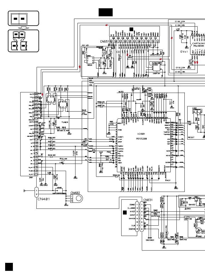
|
1 |
2 |
3 |
4 |
|
3.2 OVERALL CONNECTION DIAGRAM(GUIDE PAGE) |
|
||
|
Note: When ordering service parts, be sure to refer to " EXPLODED VIEWS AND PARTS LIST" or |
|||
A |
"ELECTRICAL PARTS LIST". |
|
|
|
|
|
Large size |
A-a |
A-a |
A-b |
SCH diagram |
|
|
|
||
|
|
|
C CN701 |
A-a |
A-b |
Guide page |
|
A-a |
A-b |
Detailed page |
|
B |
|
|
CD:+0.35dBs |
|
|
|
|
|
|
FM:-15.5dBs |
|
|
|
AM:-26.0dBs |
|
C |
|
|
|
|
UNIT TUNER FM/AM |
|
|
D |
|
|
SYSTEM CONTROLLER |
|
|
|
|
E
For resistors and capacitors in the circuit diagrams, their resistance values or |
B |
|
capacitance values are expressed in codes: |
CN1801 |
|
Ex. *Resistors |
|
|
|
|
|
Code |
Practical value |
|
123 |
12k ohms |
|
103 |
10k ohms |
|
*Capacitors |
|
|
Code |
Practical value |
|
103 |
0.01uF |
|
101/10 |
100uF/10V |
|
The > mark found on some component parts indicates the importance of the safety factor of the part. Therefore, when replacing, be sure to use parts of identical designation.
F
A
16 |
|
DEH-1630R/XU/EW |
|
|
1 |
2 |
|
3 |
4 |
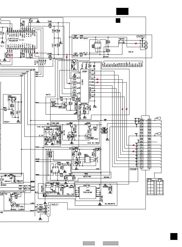
5 |
6 |
7 |
|
|
|
8 |
|
|
A-b |
|
|
|
A |
|
|
|
|
|
|
|
|
|
A TUNER AMP UNIT |
|
|
|
|
|
|
> |
|
|
|
|
|
|
|
REAR |
|
|
|
|
|
3A |
L CH |
|
|
|
|
|
|
|
|
|
|
|
|
|
REAR |
|
|
|
FM: +6.6dBs |
|
R CH |
|
|
B |
|
|
|
|
|
|||
AM: |
-2.9dBs |
|
|
|
|
|
CD:+10.45dBs |
|
|
|
|
|
|
|
332/16 |
|
|
|
|
|
|
TDA7386 |
|
|
|
|
|
|
|
|
|
|
|
C |
|
2R2/50 |
|
FM: +32.6dBs |
|
|
|
|
|
|
|
|
|
|
|
|
|
AM: +23.1dBs |
|
|
|
|
|
|
CD:+36.45dBs |
|
|
|
|
|
|
FUSE |
|
|
|
|
|
|
CEK1208 |
|
|
|
|
|
|
10A |
|
|
|
|
600 H |
|
> |
BACK UP |
|
|
|
|
|
|
GND |
|
|
|
|
|
|
ACC |
|
|
|
|
|
|
B.REM |
|
D |
|
|
|
|
|
|
|
|
|
|
|
TEL MUTE |
|
|
|
|
|
|
RL- |
|
|
|
|
|
|
FL- |
|
|
|
|
|
|
RL+ |
|
|
|
|
|
|
FL+ |
|
|
|
|
|
|
RR- |
|
|
|
|
|
|
FR- |
|
|
|
|
|
|
RR+ |
|
|
|
|
|
|
FR+ |
|
|
|
|
|
|
RR |
RR |
E |
|
|
|
|
- |
+ |
|
|
|
|
BACK |
FR |
FR |
|
|
|
|
UP |
- |
+ |
|
|
|
|
B. |
FL |
FL |
|
|
|
|
REM |
- |
+ |
|
|
|
|
GND ACC |
RL |
RL |
|
|
|
|
- |
+ |
|
|
|
|
|
|
|
||
|
Jack for the wired |
|
|
|
|
|
|
remote control |
|
|
|
|
|
|
|
|
|
|
|
F |
|
|
|
|
|
|
A |
|
DEH-1630R/XU/EW |
7 |
|
|
|
17 |
5 |
6 |
|
|
|
8 |
|

|
1 |
2 |
3 |
4 |
A |
|
|
|
|
A-b |
1 |
|
2 |
|
B |
|
|
|
|
|
|
|
CD:+0.35dBs |
|
|
CN701 |
|
|
|
C |
C |
|
|
|
|
|
|
|
|
A-b |
|
|
|
|
A-a |
|
|
|
|
D |
|
|
|
|
E |
|
|
|
|
F |
|
|
FM:-15.5dBs |
AM:-26.0dBs |
|
|
|
||
A-a |
|
|
|
FM/AM TUNER UNIT |
|
|
|
|
|
18 |
|
|
DEH-1630R/XU/EW |
|
|
1 |
2 |
3 |
4 |
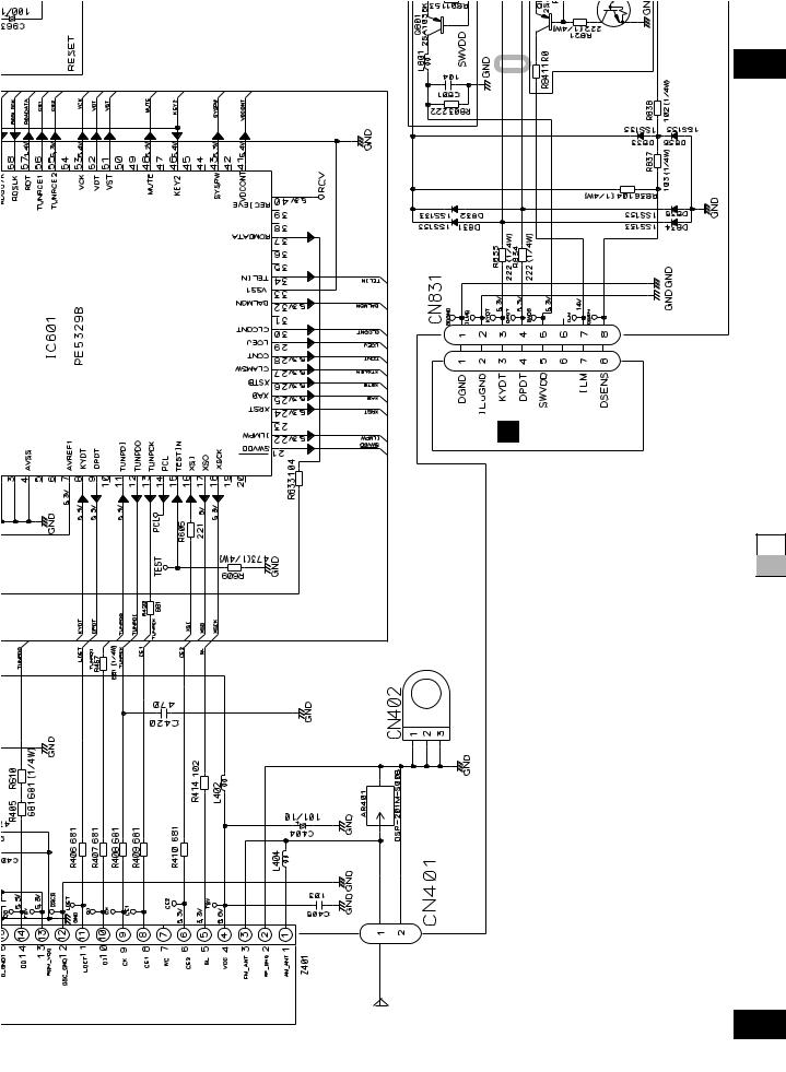
5 |
6 |
7 |
|
|
|
|
|
|
|
|
|
3 |
|
|
|
|
|
|
|
|
|
|
SYSTEM CONTROLLER |
|
|
|
|
|
|
|
|
|
|
B CN1801 |
|
|
|
|
|
||||
|
circuit diagrams, their resistance values or |
in codes: |
|
|
|
|
|
|
|
|
|
For resistors and capacitors in the |
capacitance values are expressed |
Ex. *Resistors |
Code Practical value |
123 12k ohms |
103 10k ohms |
*Capacitors |
Code Practical value |
103 0.01uF |
101/10 100uF/10V |
8
A-b
A-a A-b
The > mark found on some component parts indicates the importance of the safety factor of the part. Therefore, when replacing, be sure to use parts of identical designation.
TUNER UNIT
A-a
|
|
|
|
|
|
|
|
|
DEH- |
1630R/XU/EW |
7 |
19 |
|
5 |
6 |
|
|
|
8 |
|
A
B
C
D
E
F
Loading...