


 Loading...
ORDER NO.
CRT4230
DEH-1100MPB/XN/EW5
CD RDS RECEIVER
DEH-1100MPB/XN/EW5
DEH-1100MP/XN/EW5
DEH-1120MP/XN/EW5
This service manual should be used together with the following manual(s):
Model No. |
Order No. |
Mech.Module |
|
|
|
Remarks |
|||||||
|
|
|
|
|
|
|
|
|
|
|
|
|
|
CX-3195 |
CRT3815 |
S10.5COMP2 |
CD Mech. Module : Circuit Descriptions, Mech. Descriptions, Disassembly |
||||||||||
|
|
|
|
|
|
|
|
|
|
|
|
|
|
|
|
|
|
|
|
|
|
|
|
|
|
|
|
|
|
|
|
|
|
|
|
|
|
|
|
|
|
|
|
|
|
|
|
|
|
|
|
|
|
|
|
|
|
|
|
|
|
|
|
|
|
|
|
|
|
|
|
|
|
|
|
|
|
|
|
|
|
|
|
|
|
|
|
|
|
|
|
|
|
|
|
|
|
For details, refer to "Important Check Points for Good Servicing".
PIONEER CORPORATION 4-1, Meguro 1-chome, Meguro-ku, Tokyo 153-8654, Japan PIONEER ELECTRONICS (USA) INC. P.O. Box 1760, Long Beach, CA 90801-1760, U.S.A. PIONEER EUROPE NV Haven 1087, Keetberglaan 1, 9120 Melsele, Belgium
PIONEER ELECTRONICS ASIACENTRE PTE. LTD. 253 Alexandra Road, #04-01, Singapore 159936
 PIONEER CORPORATION 2008
K-ZZZ. OCT. 2008 Printed in Japan

|
1 |
|
2 |
|
3 |
|
4 |
|
SAFETY INFORMATION
This service manual is intended for qualified service technicians; it is not meant for the casual do-it-yourselfer.
Qualified technicians have the necessary test equipment and tools, and have been trained to properly and safety
A
repair complex products such as those covered by this manual.
Improperly performed repairs can adversely affect the safety and reliability of the product and may void the warranty. If you are not qualified to perform the repair of this product properly and safety, you should not risk trying to do so and refer the repair to a qualified service technician.
Where in a manufacturer’s service documentation, for example in circuit diagrams or lists
of components, a symbol is used to indicate that a specific component shall be replaced only by the component specified in that documentation for safety reasons, the following symbol shall be used:
B
-Safety Precautions for those who Service this Unit.
When checking or adjusting the emitting power of the laser diode exercise caution in order to get safe, reliable results.
Caution:
1.During repair or tests, minimum distance of 13 cm from the focus lens must be kept.
2.During repair or tests, do not view laser beam for 10 seconds or longer.
CAUTION:
C
USE OF CONTROLS OR ADJUSTMENTS OR PERFORMANCE OF PROCEDURES OTHER THAN THOSE SPECIFIED HEREIN MAY RESULT IN HAZARDOUS RADIATION EXPOSURE.
CAUTION
CLASS 1M INVISIBLE LASER RADIATION WHEN OPEN. DO NOT VIEW DIRECTLY WITH OPTICAL INSTRUMENTS
WARNING!
DThe AEL (accessible emission level )of the laser power output is less than CLASS 1 but the laser component is capable of emitting radiation exceeding the limit for CLASS 1.
A specially instructed person should do servicing operation of the apparatus.
Laser diode characteristics
Wave length : 785 nm to 814 nm
Maximum output : 1 190 µW(Emitting period : unlimited)
E
Additional Laser Caution
Transistors Q101 in PCB drive the laser diodes.
When Q101 is shorted between their terminals, the laser diodes will radiate beam. If the top cover is removed with no disc loaded while such short-circuit is continued, the naked eyes may be exposed to the laser beam.
F
2 |
DEH-1100MPB/XN/EW5 |
|
1 |
|
2 |
|
3 |
|
4 |
|
|
|
|
|
|

|
5 |
|
6 |
|
7 |
|
8 |
[Important Check Points for Good Servicing]
In this manual, procedures that must be performed during repairs are marked with the below symbol. Please be sure to confirm and follow these procedures.
1. Product safety
Please conform to product regulations (such as safety and radiation regulations), and maintain a safe servicing environment by following the safety instructions described in this manual.
1 Use specified parts for repair.
Use genuine parts. Be sure to use important parts for safety.
2 Do not perform modifications without proper instructions.
Please follow the specified safety methods when modification(addition/change of parts) is required due to interferences such as radio/TV interference and foreign noise.
3 Make sure the soldering of repaired locations is properly performed.
When you solder while repairing, please be sure that there are no cold solder and other debris.
Soldering should be finished with the proper quantity. (Refer to the example)
4 Make sure the screws are tightly fastened.
Please be sure that all screws are fastened, and that there are no loose screws.
5 Make sure each connectors are correctly inserted.
Please be sure that all connectors are inserted, and that there are no imperfect insertion.
6 Make sure the wiring cables are set to their original state.
Please replace the wiring and cables to the original state after repairs.
In addition, be sure that there are no pinched wires, etc.
7Make sure screws and soldering scraps do not remain inside the product. Please check that neither solder debris nor screws remain inside the product.
8There should be no semi-broken wires, scratches, melting, etc. on the coating of the power cord.
Damaged power cords may lead to fire accidents, so please be sure that there are no damages.
If you find a damaged power cord, please exchange it with a suitable one.
9 There should be no spark traces or similar marks on the power plug.
When spark traces or similar marks are found on the power supply plug, please check the connection and advise on secure connections and suitable usage. Please exchange the power cord if necessary.
a Safe environment should be secured during servicing.
When you perform repairs, please pay attention to static electricity, furniture, household articles, etc. in order to prevent injuries. Please pay attention to your surroundings and repair safely.
2. Adjustments
To keep the original performance of the products, optimum adjustments and confirmation of characteristics within specification. Adjustments should be performed in accordance with the procedures/instructions described in this manual.
A
B
C
D
3. Lubricants, Glues, and Replacement parts
Use grease and adhesives that are equal to the specified substance.
Make sure the proper amount is applied.
E
4. Cleaning
For parts that require cleaning, such as optical pickups, tape deck heads, lenses and mirrors used in projection monitors, proper cleaning should be performed to restore their performances.
5. Shipping mode and Shipping screws
To protect products from damages or failures during transit, the shipping mode should be set or the shipping screws should be installed before shipment. Please be sure to follow this method especially if it is specified in this manual.
F
|
|
|
|
DEH-1100MPB/XN/EW5 |
|
|
|
3 |
|
||
|
5 |
|
6 |
|
|
7 |
|
8 |
|
|
|
|
|
|
|
|
|
||||||

|
|
1 |
|
|
2 |
|
|
3 |
|
4 |
|
|
|
CONTENTS |
|
|
|
|
|
|
|
||
|
|
SAFETY INFORMATION..................................................................................................................................... |
|
|
|
|
2 |
|
|||
|
|
1. SERVICE PRECAUTIONS ............................................................................................................................... |
|
|
|
|
5 |
|
|||
A |
1.1 SERVICE PRECAUTIONS ........................................................................................................................ |
|
|
|
|
5 |
|
||||
1.2 NOTES ON SOLDERING |
|
|
|
|
5 |
|
|||||
|
|
|
|
|
|
|
|||||
|
|
2. SPECIFICATIONS............................................................................................................................................ |
|
|
|
|
6 |
|
|||
|
|
2.1 SPECIFICATIONS ..................................................................................................................................... |
|
|
|
|
6 |
|
|||
|
|
2.2 DISC/CONTENT FORMAT ........................................................................................................................ |
|
|
|
|
7 |
|
|||
|
|
2.3 PANEL FACILITIES.................................................................................................................................... |
|
|
|
|
7 |
|
|||
|
|
2.4 CONNECTION DIAGRAM |
|
|
|
|
9 |
|
|||
|
|
|
|
|
|
|
|||||
|
|
........................................................................................................................3. BASIC ITEMS FOR SERVICE |
|
|
|
|
10 |
|
|||
|
|
3.1 CHECK POINTS AFTER SERVICING..................................................................................................... |
|
10 |
|
||||||
|
|
3.2 PCB LOCATIONS .................................................................................................................................... |
|
|
|
|
10 |
|
|||
|
|
3.3 JIGS LIST ................................................................................................................................................. |
|
|
|
|
11 |
|
|||
|
|
3.4 CLEANING................................................................................................................................................ |
|
|
|
|
11 |
|
|||
B |
4. BLOCK DIAGRAM.......................................................................................................................................... |
|
|
|
|
12 |
|
||||
|
|
5. DIAGNOSIS.................................................................................................................................................... |
|
|
|
|
16 |
|
|||
|
|
5.1 OPERATIONAL FLOWCHART ................................................................................................................ |
|
|
|
|
16 |
|
|||
|
|
5.2 ERROR CODE LIST ................................................................................................................................ |
|
|
|
|
17 |
|
|||
|
|
5.3 CONNECTOR FUNCTION DESCRIPTION............................................................................................. |
|
18 |
|
||||||
|
|
6. SERVICE MODE ............................................................................................................................................ |
|
|
|
|
18 |
|
|||
|
|
6.1 DISPLAY TEST MODE |
|
|
|
|
18 |
|
|||
|
|
|
|
|
|
|
|||||
|
|
|
|
|
|
|
|||||
|
|
6.2 CD TEST MODE...................................................................................................................................... |
|
|
|
|
19 |
|
|||
|
|
7. DISASSEMBLY .............................................................................................................................................. |
|
|
|
|
20 |
|
|||
|
|
8. EACH SETTING AND ADJUSTMENT ........................................................................................................... |
|
|
|
|
23 |
|
|||
|
|
8.1 CD ADJUSTMENT................................................................................................................................... |
|
|
|
|
23 |
|
|||
C |
8.2 CHECKING THE GRATING AFTER CHANGING THE PICKUP UNIT |
.................................................... |
24 |
|
|||||||
9. EXPLODED VIEWS AND PARTS LIST |
|
|
|
|
26 |
|
|||||
|
|
|
|
|
|
|
|||||
|
|
9.1 PACKING ................................................................................................................................................. |
|
|
|
|
26 |
|
|||
|
|
9.2 EXTERIOR(1) .......................................................................................................................................... |
|
|
|
|
28 |
|
|||
|
|
9.3 EXTERIOR(2) .......................................................................................................................................... |
|
|
|
|
30 |
|
|||
|
|
9.4 CD MECHANISM MODULE..................................................................................................................... |
|
|
|
|
32 |
|
|||
|
|
10. SCHEMATIC DIAGRAM............................................................................................................................... |
|
|
|
|
34 |
|
|||
|
|
|
|
|
|
|
|||||
|
|
10.1 TUNER AMP UNIT(GUIDE PAGE) |
|
|
|
|
34 |
|
|||
|
|
|
|
|
|
|
|||||
|
|
10.2 KEYBOARD UNIT.................................................................................................................................. |
|
|
|
|
40 |
|
|||
|
|
10.3 CD MECHANISM MODULE(GUIDE PAGE) .......................................................................................... |
|
42 |
|
||||||
|
|
10.4 WAVEFORMS ........................................................................................................................................ |
|
|
|
|
48 |
|
|||
|
|
11. PCB CONNECTION DIAGRAM.................................................................................................................... |
|
|
|
|
50 |
|
|||
D |
11.1 TUNER AMP UNIT................................................................................................................................. |
|
|
|
|
50 |
|
||||
11.2 KEYBOARD UNIT |
|
|
|
|
54 |
|
|||||
|
|
|
|
|
|
|
|||||
|
|
11.3 CD CORE UNIT(S10.5COMP2)............................................................................................................. |
|
|
|
|
56 |
|
|||
|
|
12. ELECTRICAL PARTS LIST .......................................................................................................................... |
|
|
|
|
58 |
|
|||
|
|
|
|
|
|
|
|
|
|
|
|
|
|
|
|
|
|
|
|
|
|
|
|
E
F
4 |
DEH-1100MPB/XN/EW5 |
|
1 |
|
2 |
|
3 |
|
4 |
|
|
|
|
|
|

|
5 |
|
6 |
|
7 |
|
8 |
1. SERVICE PRECAUTIONS
1.1SERVICE PRECAUTIONS
1.You should conform to the regulations governing the product (safety, radio and noise, and other regulations), and should keep the safety during servicing by following the safety instructions described in this manual.
2.Before disassembling the unit, be sure to turn off the power. Unplugging and plugging the connectors during power-on mode may damage the ICs inside the unit.
3.To protect the pickup unit from electrostatic discharge during servicing, take an appropriate treatment (shorting-solder) by referring to "the DISASSEMBLY".
4.After replacing the pickup unit, be sure to check the grating.
5.Be careful in handling ICs. Some ICs such as MOS type are so fragile that they can be damaged by electrostatic induction.
1.2NOTES ON SOLDERING
A
B
C
 For environmental protection, lead-free solder is used on the printed circuit boards mounted in this unit.
Be sure to use lead-free solder and a soldering iron that can meet specifications for use with lead-free solders for repairs accompanied by reworking of soldering.
 Compared with conventional eutectic solders, lead-free solders have higher melting points, by approximately 40
  C. Therefore, for lead-free soldering, the tip temperature of a soldering iron must be set to around 373
  C in general, although the temperature depends on the heat capacity of the PC board on which reworking is required and the weight of the tip of the soldering iron.
Compared with eutectic solders, lead-free solders have higher bond strengths but slower wetting times and higher melting temperatures (hard to melt/easy to harden).
The following lead-free solders are available as service parts:
 Parts numbers of lead-free solder:
GYP1006 1.0 in dia.
GYP1007 0.6 in dia.
GYP1008 0.3 in dia.
|
|
|
|
DEH-1100MPB/XN/EW5 |
|
|
|
5 |
||
|
5 |
|
6 |
|
|
7 |
|
8 |
|
|
|
|
|
|
|
||||||
D
E
F
|
|
1 |
|
|
2 |
|
|
|
|
2. SPECIFICATIONS |
|
|
|||
|
|
2.1 SPECIFICATIONS |
|
|
|||
A |
|
|
|
|
|
|
|
|
|
General |
|
|
|
||
|
|
Power source......................... |
14.4 V DC (10.8 V to 15.1 V |
|
|||
|
|
|
|
|
allowable) |
|
|
|
|
Grounding system |
Negative type |
|
|
||
|
|
|
|
||||
|
|
Max. current consumption |
|
|
|
||
|
|
............................................... |
|
|
10.0 A |
|
|
|
|
Backup current ....................... |
2 mA or less |
|
|
||
|
|
Dimensions (W × H × D): |
|
|
|
||
B |
DIN |
|
|
|
|||
|
|
Chassis .................. |
178 mm × 50 mm × 162 |
|
|||
|
|
|
|
|
mm |
|
|
|
|
Nose ........................ |
188 mm × 58 mm × 15 mm |
|
|||
|
|
D |
|
|
|
||
|
|
Chassis .................. |
178 mm × 50 mm × 162 |
|
|||
|
|
|
|
|
mm |
|
|
|
|
|
|
|
|
|
|
|
|
|
|
|
|
|
|
|
|
Nose ........................ |
170 mm × 48 mm × 15 mm |
|
|||
|
|
Weight ..................................... |
1.3 kg |
|
|
||
|
|
Audio |
|
|
|
||
C |
Maximum power output ....... |
50 W × 4 |
|
|
|||
Continuous power output |
22 W × 4 (50 Hz to 15 000 |
|
|||||
|
|
|
|||||
|
|
|
|
|
Hz, 5% THD, 4 |
load, both |
|
|
|
|
|
|
channels driven) |
|
|
|
|
Load impedance .................... |
4 (4 to 8 allowable) |
|
|||
|
|
Preout max output level ....... |
2.0 V |
|
|
||
|
|
Tone controls: |
|
|
|
||
|
|
|
|
|
|||
|
|
Bass |
|
|
|
||
|
|
Frequency.............. |
100 Hz |
|
|
||
|
|
Gain ......................... |
±13 dB |
|
|
||
|
|
Mid |
|
|
|
||
|
|
Frequency.............. |
1 kHz |
|
|
||
D |
Gain ......................... |
±12 dB |
|
|
|||
|
|
Treble |
|
|
|
||
|
|
Frequency.............. |
10 kHz |
|
|
||
|
|
Gain ......................... |
±12 dB |
|
|
||
|
|
CD player |
|
|
|
||
|
|
System |
Compact disc audio system |
|
|||
|
|
|
|||||
|
|
Usable discs .......................... |
Compact disc |
|
|
||
|
|
Signal-to-noise ratio............. |
94 dB (1 kHz) (IEC-A net- |
|
|||
|
|
|
|
|
work) |
|
|
|
|
Number of channels ............ |
2 (stereo) |
|
|
||
E |
WMA decoding format ....... |
Ver. 7, 7.1, 8, 9, 10, 11 (2ch |
|
||||
|
|
|
audio) |
|
|
||
|
|
|
|
|
|
|
|
|
|
|
|
|
(Windows Media Player) |
|
|
|
|
MP3 decoding format .......... |
MPEG-1 & 2 Audio Layer 3 |
|
|||
|
|
WAV signal format ................ |
Linear PCM & MS ADPCM |
|
|||
|
|
FM tuner |
|
|
|
||
|
|
|
|
|
|||
|
|
...................Frequency range |
87.5 MHz to 108.0 MHz |
|
|||
|
|
Usable sensitivity.................. |
11 dBf (0.7 μV/75 |
, mono, |
|
||
|
|
|
|
|
S/N: 30 dB) |
|
|
|
|
Signal-to-noise ratio............. |
72 dB (IEC-A network) |
|
|||
F
3 |
|
4 |
|
MW tuner
Frequency range................... |
531 kHz to 1 602 kHz |
Usable sensitivity.................. |
25 μV (S/N: 20 dB) |
Signal-to-noise ratio............. |
62 dB (IEC-A network) |
LW tuner
Frequency range................... |
153 kHz to 281 kHz |
Usable sensitivity.................. |
28 μV (S/N: 20 dB) |
Signal-to-noise ratio............. |
62 dB (IEC-A network) |
 Note
Note
Specifications and the design are subject to modifications without notice due to improvements.
6 |
DEH-1100MPB/XN/EW5 |
|
1 |
|
2 |
|
3 |
|
4 |
|
|
|
|
|
|
|
5 |
|
6 |
2.2DISC/CONTENT FORMAT
2.3PANEL FACILITIES
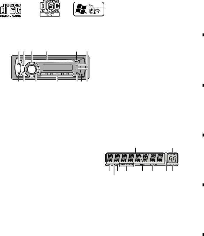
What ’s what
Head unit
12 3 |
4 |
5 |
6 |
dc b a 987
1 FUNCTION button
Press to recall the function menu when operating a source.
2 AUDIO button
Press to select various sound quality controls.
3  /
/ /
/ /
/ buttons
Press to perform manual seek tuning, fast forward, reverse and track search controls. Also used for controlling functions.
4Disc loading slot
Insert a disc to play.
5EJECT button
Press to eject a CD from your built-in CD player.
6 DISPLAY button
Press to select different displays.
Press and hold to scroll through the text information.
7 TA button
Press to turn TA function on or off. Press and hold to turn AF function on or off.
8 DETACH button
Press to remove the front panel from the head unit.
9 AUX input jack (3.5 mm stereo jack)
Use to connect an auxiliary device.
|
7 |
|
8 |
|
A
a 1 to 6 buttons
Press for preset tuning.
b SOURCE button, VOLUME
This unit is turned on by selecting a source. Press to cycle through all the available
sources. B Press and hold to recall the initial setting
menu when the sources are off.
Rotate it to increase or decrease the volume.
c EQ button
Press to select various equalizer curves. Press and hold to turn loudness on or off.
d BAND button |
C |
|
Press to select among MW/LW and two FM bands and cancel the control mode of functions.
Display indication |
|
|
|
|
1 |
|
2 |
|
|
|
D |
345 6 |
7 |
8 |
9 a |
1 Main display section
Shows the various information such as band, play time, and other setting.
•Tuner
Band and frequency are displayed.
• RDS |
E |
Program service name, PTY information |
|
and other literal information are dis- |
|
played. |
|
•Built-in CD Player
Elapsed playback time and literal information are displayed.
2 Preset number/track number indicator
Shows the track number or preset number.
F
|
|
|
|
DEH-1100MPB/XN/EW5 |
|
|
|
7 |
|
||
|
5 |
|
6 |
|
|
7 |
|
8 |
|
|
|
|
|
|
|
|
|
||||||

|
1 |
|
2 |
|
A
•If a track number 100 or more is selected,  on the left of the track number indicator will light.
|
|
3 |
AF indicator |
|
|
||
|
|
|
Appears when AF (alternative frequencies |
|
|
|
search) function is on. |
B |
4 TP indicator |
||
|
|
|
Appears when a TP station is tuned in. |
|
|
5 |
TA indicator |
|
|
|
Appears when TA (traffic announcement |
|
|
|
standby) function is on. |
|
|
|
|
|
|
6 |
MP3/WMA indicator |
|
|
7 |
RPT indicator |
C |
|
Shows when repeat play is turned on. |
|
|
|
|
|
|
|
8 |
LOUD indicator |
|
|
|
Appears when loudness is on. |
|
|
9 |
(stereo) indicator |
|
|
||
|
|
|
Appears when the selected frequency is |
|
|
|
being broadcast in stereo. |
a LOC indicator
Appears when local seek tuning is on
D
E
F
3 |
|
4 |
|
Fastening the front panel
If you do not plan to detach the front panel, the front panel can be fastened with supplied screw.
Screw
BPZ20P080FTC
8 |
DEH-1100MPB/XN/EW5 |
|
1 |
|
2 |
|
3 |
|
4 |
|
|
|
|
|
|
5
1100MPB/XN/EW5-DEH 7 6
8
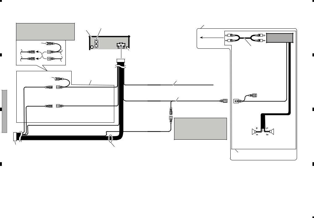
4 Note: |
|
1 This product |
19 Rear output |
|
Depending on the kind of vehicle, the function |
(DEH-1120MP/DEH-1100MPB/ |
|||
|
||||
of 3* and 5* may be different. In this case, be |
|
DEH-1100MP) |
||
sure to connect 2* to 5* and 4* to 3*. |
|
|
||
|
1* |
|
|
|
3* |
2* |
|
|
|
|
2 Antenna jack |
3 Fuse (10 A) |
||
5* |
4* |
|
|
|
6Cap (1*)
Do not remove cap if this terminal is not in use.
7Yellow (3*) Back-up
(or accessory)
9Red (5*) Accessory (or back-up)
5 Connect leads of the same color to each other.
8Yellow (2*)
Connect to the constant 12 V supply terminal.
10Red (4*)
Connect to terminal controlled by ignition switch (12 V DC).
11 Black (chassis ground)
Connect to a clean, paint-free metal location.
12ISO connector
In some vehicles, the ISO connector may be divided into two. In this case, be sure to connect to both connectors.
13Speaker leads
White: Front left White/black: Front left
 Gray: Front right
  Gray/black: Front right
 Green: Rear left
 Green/black: Rear left
 Violet: Rear right
 Violet/black: Rear right
20 This diaglam is for DEH-1120MP/DEH-1100MPB/DEH-1100MP.
21 To Rear output


 14 Wired remote input
Hard-wired remote control adaptor can be connected (sold separately).
15 Yellow/black
If you use an equipment with Mute function, wire this lead to the Audio Mute lead on that equipment. If not, keep the Audio Mute lead free of any connections.
16 Blue/white
Connect to system control terminal of the power amp (max. 300 mA 12 V DC).
17 Blue/white (7*)
Connect to auto-antenna relay control terminal (max. 300 mA 12 V DC).
18 Blue/white (6*)
The pin position of the ISO connector will differ depends on the type of vehicle. Connect 6* and 7* when Pin 5 is an antenna control type. In another type of vehicle, never connect 6* and 7*.
23 Power amp (sold separately)
22Connect with RCA cables (sold separately)
24 System remote control
25 Left |
26 Right |
27 Rear speaker |
27 Rear speaker |
28Perform these connections when using the optional amplifier.
9
|
F |
|
E |
|
D |
|
C |
|
B |
|
A |
|
|
|
|
|
|
DIAGRAM CONNECTION 4.2
5
6
7
8

|
1 |
|
2 |
|
3 |
|
4 |
|
3. BASIC ITEMS FOR SERVICE
3.1 CHECK POINTS AFTER SERVICING
A
To keep the product quality after servicing, please confirm following check points.
|
|
No. |
|
Procedures |
|
Item to be confirmed |
|
|
1 |
|
Confirm whether the customer complain has |
|
The customer complain must not be |
|
|
|
|
been solved. |
|
reappeared. |
|
|
|
|
If the customer complain occurs with the |
|
Display, audio and operations must be |
|
|
|
|
|||
|
|
|
|
specific media, use it for the operation check. |
|
normal. |
|
|
2 |
CD |
Play back a CD. |
|
No malfunction on display, audio and |
|
|
|
|
(Track search) |
|
operation. |
|
|
3 |
FM/AM tuner |
Check FM/AM tuner action. |
|
Display, audio and operations must be |
B |
|
|
(Seek, Preset) |
|
normal. |
|
|
|
|
|
Switch band to check both FM and AM. |
|
|
|
|
4 |
|
Check whether no disc is inside the product. |
|
The media used for the operating check must |
|
|
|
|
|
|
be ejected. |
|
|
5 |
|
Appearance check |
|
No scratches or dirt on its appearance after |
|
|
|
|
|
|
receiving it for service. |
|
|
|
See the table below for the items to be checked regarding audio: |
|
||
|
|
|
|
|||
|
|
|
|
|
|
|
|
|
|
|
Item to be checked regarding audio |
|
|
|
|
|
|
|
|
|
|
|
|
|
Distortion |
|
|
C |
|
Noise |
|
|
||
|
Volume too low |
|
|
|||
|
|
|
|
|
|
|
|
|
|
|
Volume too high |
|
|
|
|
|
|
Volume fluctuating |
|
|
|
|
|
|
Sound interrupted |
|
|
|
|
|
|
|
|
|
|
|
|
|
|
|
|
|
|
|
|
|
|
|
3.2 PCB LOCATIONS
D
E
C CD Core Unit (S10.5COMP2)
A Tuner Amp Unit
B Keyboard Unit
|
Unit Number |
: |
|
QWM3032 |
Unit Number |
: |
|
(1100MP) |
|
|||||
F |
Unit Name |
: |
|
Tuner Amp Unit |
Unit Number |
: |
|
(1100MPB) |
|
|||||
Unit Number |
: |
|
(1120MP) |
Unit Name |
: |
|
Keyboard Unit |
|
||||||
|
|
|
|
|||||||||||
|
Unit Name |
: |
|
Keyboard Unit |
Unit Number |
: |
|
CWX3514 |
|
|||||
|
|
|
|
|
|
Unit Name |
: |
|
CD Core Unit(S10.5COMP2) |
|
||||
|
|
|
|
|
|
|
|
|
|
|
|
|
|
|
|
10 |
|
|
|
DEH-1100MPB/XN/EW5 |
|
|
|
|
|
|
|||
|
1 |
|
|
2 |
|
|
|
|
|
3 |
|
|
4 |
|
|
|
|
|
|
|
|
|
|
|
|||||
|
5 |
|
6 |
|
7 |
|
8 |
|
3.3 JIGS LIST
- Jigs List |
A |
Remarks
TCD-782 Checking the grating
Checking the grating (Two pieces)
- Grease List
|
|
|
|
|
Remarks |
|
B |
|
|
|
|
|
|
|
|
|
|
|
|
|
|
CD Mechanism Module |
|
|
||
|
|
GEM1045 |
CD Mechanism Module |
|
||||
|
|
|
|
|
|
|
|
|
|
|
|
|
|
|
|
|
|
C
3.4 CLEANING
Before shipping out the product, be sure to clean the following portions by using the prescribed cleaning tools:
Portions to be cleaned |
Cleaning tools |
CD pickup lenses |
Cleaning liquid : GEM1004 |
|
Cleaning paper : GED-008 |
|
|
|
|
DEH-1100MPB/XN/EW5 |
|
|
|
11 |
||
|
5 |
|
6 |
|
|
7 |
|
8 |
|
|
|
|
|
|
|
||||||
D
E
F

|
1 |
|
2 |
|
3 |
|
4 |
|
4. BLOCK DIAGRAM
A |
A TUNER AMP UNIT |
|
|
|
|
|
|
|
|
|
|
|
|
|
|
|
|
|
|
|
|
|
|
|
|
|
|
|
|
|
|
|
|
|
|
|
|
|
|
|
|
|
|
||
ANTENNA |
CN401 |
|
|
|
|
|
SYS+B |
|
|
|
|
|
|
SWVDD |
|
|
|
|
|
|
|
|
|
|
|
|
|
SL-IN |
IFA |
IFB |
|
REFA |
REFB |
LDET |
|
DI |
CK |
CE1 |
DO |
CE2 |
SLOUT |
|
|
||
|
ANTAM |
|
|
|
|
|
|
|
|
|
||||||||||||
|
1 |
|
|
|
|
|
|
|
|
|
|
|
|
|
|
|
|
|
|
|
|
|
|
2 |
|
|
|
|
|
|
|
|
|
|
|
|
|
|
|
|
|
|
|
|
|
|
1 |
2 |
3 |
4 |
5 |
6 |
7 |
8 |
9 |
10 |
11 |
12 |
13 |
14 |
15 |
16 |
17 |
18 |
19 |
20 |
|
|
|
ANT |
RFGND1 |
RFGND2 |
RFGND3 |
RFGND4 |
VCC |
SLIN |
IFOUTA |
IFOUTB |
DGND |
REFINA |
REFINB |
LDET |
VDD |
DI |
CK |
CE1 |
DO |
CE2 |
SLOUT |
|
|
|
|
|
|
|
|
|
|
|
|
|
|
|
|
|
|
|
|
IC2 |
|
SL-IN |
|
|
|
|
|
|
|
|
|
|
|
|
|
|
|
|
|
|
|
EEPROM |
|
|
|||
|
|
|
|
|
|
|
|
|
|
|
|
|
|
|
|
|
|
|
|
IFA |
|
|
|
|
|
|
|
|
|
|
|
|
|
|
|
|
|
|
|
|
|
|
IFB |
|
|
|
|
|
|
|
|
|
|
|
|
|
|
|
|
|
|
|
|
|
|
REFA |
|
|
|
|
|
|
|
|
|
|
|
|
|
|
|
|
|
|
|
|
|
|
REFB |
|
|
B |
|
|
|
|
|
|
|
|
|
|
|
|
|
|
|
|
|
|
|
LDET |
|
|
|
|
|
|
|
|
|
|
|
|
|
|
|
|
|
|
|
|
|
DI |
|
|
|
|
|
|
|
|
|
|
|
|
|
|
|
|
|
|
|
|
|
|
|
CK |
|
|
|
|
|
|
|
|
|
|
|
|
|
|
|
|
|
|
|
|
|
|
CE1 |
|
|
|
|
|
|
|
|
|
|
|
|
|
|
|
|
|
|
|
|
|
|
DO |
|
|
|
|
|
|
|
|
|
|
|
|
|
|
VCO |
|
LFP |
|
|
|
|
CE2 |
|
|
|
|
|
|
|
|
|
|
|
|
|
|
|
|
|
|
|
|
|
|
|
|
|
|
|
|
|
|
|
|
|
|
|
|
|
|
|
|
|
|
|
|
|
|
SLOUT |
||
|
|
|
ATT |
|
|
|
|
|
ATT |
|
|
|
|
|
|
|
|
|
|
|
|
|
|
|
|
|
|
|
|
|
TANK |
|
|
|
|
|
|
|
|
|
|
|
|
|
|
|
|
|
|
|
|
|
|
|
|
|
|
|
|
|
|
|
|
|
|
|
|
|
|
|
|
|
|
|
|
|
|
|
|
|
|
|
|
IC1 |
|
|
|
|
|
|
|
|
|
|
|
|
|
|
|
|
|
|
|
|
|
MIX / IF / PLL |
|
|
|
|
|
|
||
|
|
|
ATT |
|
|
|
|
RF |
|
|
LFP |
|
|
|
|
|
|
|
|
|
|
|
|
|
|
|
|
|
|
|
|
|
|
|
|
|
|
|
|
|
|
|
|
|
ELEC |
|
|
|
|
|
|
|
|
|
|
|
|
|
|
|
CF |
|
|
|
|
|
|
SOU |
|
FM/AM TUNER UNIT |
|
|
|
|
|
|
|
|
|
|
|
|
|
|
|
|
|
||||
C |
|
|
|
|
|
|
|
|
|
|
|
|
|
|
|
|
|
|
||||
|
|
|
|
|
|
|
|
|
|
|
|
|
|
|
|
|
|
|
TUNL |
1 |
|
|
|
|
|
|
|
|
|
|
|
|
|
|
|
|
|
|
|
|
|
|
|
IN1_L |
|
CDL 2 IN2_L
SYSPW
|
SYSTEM M |
|
COMPU |
|
IC 601(2 |
REGULATOR IC |
PN5016 |
D |
|
|
|
|
|
|
|
C |
CD CORE UNIT(S10.5COMP2) |
|
|
|
|
|
|
|
|
|
|
|
|
|
|
|
|
|
|
|
|
|
|
|
|
|
|
|
|
|
|
|
|
|
|
|
|
|
|
|
1 |
47 |
|
POWEROFF |
|||||||||||||||||||||||||||
|
|
|
|
|
|
|
|
|
|
|
|
|
|
|
|
|
|
|
|
|
|
|
|
|
|
|
|
|
|
|
|
|
|
|
|
5 |
|
|
|
|
|
|
|
2 |
36 |
|
|||||||||||||||||||||||||||||||||
|
|
|
PICKUP UNIT |
|
|
|
|
|
|
|
|
|
|
|
|
|
|
|
|
|
|
|
|
|
|
|
|
|
|
|
|
|
|
|
|
|
|
|
|
|
|
|
SWD5V |
|
|
|
|
|
|
|
|
|
|
|
|
BSENS |
|||||||||||||||||||||||
|
|
|
|
|
|
|
D |
|
|
|
|
|
|
|
|
|
RF-AMP, CD DECODER, |
|
|
|
|
|
|
|
|
|
|
|
|
|
|
|
|
|
SWVDD |
|
|
6 |
|
|
|
IC 911 |
3 |
15 |
|
TOP41 |
|||||||||||||||||||||||||||||||||
|
|
|
|
|
|
|
|
|
|
|
|
|
|
|
|
|
|
|
|
|
|
|
|
|
|
|
|
|
|
|
|
|
|
|
7 |
4 |
1 |
|
|||||||||||||||||||||||||||||||||||||||||
|
|
|
(P10.5)(SERVICE) |
|
|
|
|
|
|
|
|
|
|
|
|
MP3/WMA DECODER, |
|
|
|
|
|
|
|
|
|
|
|
|
|
|
|
|
|
SYS+B |
|
|
|
|
|
BA49181-V12 |
|
SWVDD |
|||||||||||||||||||||||||||||||||||||
|
|
|
|
|
|
|
|
|
|
|
|
|
|
|
|
|
|
|
|
|
|
|
|
|
|
|
|
|
|
|
|
|
8 |
|
|
|
|
|
|
|
|
|
|
|
|
|
|
|
|||||||||||||||||||||||||||||||
|
|
|
|
|
|
|
|
|
|
|
|
|
|
|
|
|
|
|
|
|
|
|
|
|
|
|
|
|
|
|
|
|
|
|
|
|
|
|
|
|
|
|
|
|
|
|
|||||||||||||||||||||||||||||||||
|
|
|
|
|
|
|
|
|
|
|
|
|
|
|
|
|
|
|
|
|
|
|
DIGITAL SERVO / |
|
|
|
|
|
|
|
|
|
|
|
|
|
|
|
|
|
|
|
VDD |
|
|
|
|
|
|
|
|
|
|
|
10 |
|
|
|
|
B.UP |
|
||||||||||||||||||
|
|
|
|
|
|
|
|
|
|
|
|
|
|
|
|
|
|
|
|
|
|
|
|
|
|
|
|
|
|
|
|
|
|
|
|
|
|
|
|
|
|
|
|
|
|
|
|
|
|
|
|
|
|
|
|
|
|
|
|
|
|
|
|
|
|
|
|
|
|||||||||||
|
|
LASER |
|
|
|
|
|
|
|
|
CN101 |
|
|
|
|
VDD |
|
|
DATA PROCESSOR |
|
|
|
|
|
|
|
|
CN701 |
|
|
|
|
CN651 |
|
|
|
|
|
|
|
|
|
|
|
9 |
|
|
|
|
|
|
|
|||||||||||||||||||||||||||
|
|
DIODE |
|
|
|
LD- 15 |
15 |
|
|
|
|
|
|
|
|
|
|
|
|
|
141 |
|
|
LD |
|
|
|
|
|
|
|
|
|
|
|
|
|
|
|
|
|
|
|
|
|
|
|
|
|
|
|
|
|
|
|
|
|
|
|
|
|
|
|
|
|
|
|
|
|
|
|
|
|||||||
|
|
|
|
|
|
|
|
|
|
|
|
|
|
Q101 |
|
|
|
|
|
|
|
|
|
|
|
|
|
|
|
|
|
|
|
|
|
|
|
|
|
|
|
|
|
|
|
|
|
|
|
|
|
|
|
|
|
|
|
|
|
|
|
|
|
|
|
|
|
|
|
|
|
|
|
||||||
|
|
|
|
|
|
|
|
|
|
MD |
5 |
5 |
|
|
|
|
|
|
|
|
|
REFO |
|
|
142 |
|
|
PD |
LOUT |
55 |
|
|
|
|
|
|
|
|
|
LOUT |
13 |
3 |
|
LOUT |
|
|
|
|
|
|
|
|
|
|
|
|
|
|
|
|
|
|
|
|
|||||||||||||||
|
|
|
|
|
|
|
|
|
|
|
|
|
|
|
|
|
|
|
|
|
|
|
|
|
|
|
|
|
|
|
|
|
|
|
|
|
|
|
|
|
|
|
|
|
|
|
|
|
|
|
|
|
|||||||||||||||||||||||||||
|
|
|
|
|
|
|
|
|
|
VREF |
|
|
|
|
|
|
|
|
|
|
|
133 |
|
|
|
|
|
|
|
|
|
|
|
|
|
|
|
|
|
|
|
|
|
|
|
|
|
|
|
|
|
|
|
|
|
|
|
|
|
|
|
|
|
|
|
||||||||||||||
|
|
|
|
|
|
|
|
|
|
8 |
|
8 |
|
|
|
|
|
|
|
|
|
|
AC,BD,F,E |
|
|
|
REFOUT |
|
|
|
|
|
|
|
|
|
|
|
|
|
|
|
|
|
|
|
|
|
|
|
|
|
|
|
|
|
|
|
|
|
|
|
|
|
|
|
|
|
|
|
SWVDD |
|
|||||||
|
|
|
|
|
|
|
HOLOGRAM |
|
|
|
|
|
|
|
|
|
|
|
|
|
|
|
|
|
|
|
|
|
|
XTAL |
|
50 |
|
|
|
|
|
|
|
|
|
|
|
|
|
|
|
|
|
|
|
|
|
|
|
|
|
|
|
|
|
|
|
|
|
|
|
|
|
|
|
|
|
|
|
|
|||
|
|
|
|
|
|
|
UNIT |
|
|
FOM |
3 |
3 |
FOM |
|
|
|
|
|
|
CD |
|
|
|
|
|
|
|
|
|
X201 |
|
|
|
|
|
|
|
|
|
|
|
|
|
|
|
|
|
|
|
|
|
|
|
|
|
|
Q601 |
|
|
|
|
85 |
|
DREG |
|||||||||||||||
|
|
|
|
|
|
|
|
|
|
FOP |
FOP |
|
|
|
|
|
|
|
|
|
|
|
/XTAL |
52 |
|
|
16.93MHz |
|
|
|
|
|
|
|
|
|
|
|
|
|
|
|
|
|
|
|
|
|
|
|
|
|
|
|
|
|
|
|
|
|
|
|
|
|
|||||||||||||||
|
|
|
|
MONITOR |
FOCUS ACT. |
2 |
2 |
|
|
|
|
|
|
DRIVER |
|
|
|
|
|
|
|
|
|
|
|
|
|
|
|
|
|
|
|
|
|
|
|
|
|
|
|
|
|
|
|
|
|
|
|
|
|
|
|
|
|
|
|
9 |
|
|
|||||||||||||||||||
|
|
|
|
TRACKING ACT. |
TOP |
1 |
1 |
TOP |
|
|
|
|
|
|
|
|
|
|
|
|
|
|
|
|
|
|
|
|
|
|
|
|
|
|
|
|
|
|
|
|
|
|
|
|
|
|
|
|
|
|
|
|
|
|
|
|
|
|
|
|
|
|
|
|
|
|
|
|
REGC(M) |
||||||||||
|
|
|
|
|
DIODE |
|
|
|
TOM |
4 |
|
4 |
TOM |
|
|
|
|
|
|
IC301 |
|
|
|
|
IC201 |
|
|
|
|
|
|
|
|
VDD |
|
|
|
|
|
|
|
|
|
|
|
|
|
|
|
|
|
|
|
|
|
|
|
|
|
|
|
|
|
|
55 |
|
PLL_VDD |
||||||||||||
|
|
|
|
|
|
|
|
|
|
LD+ |
14 |
14 |
|
|
|
|
|
|
|
|
|
|
BA5839FP |
TD,FD |
|
|
|
|
|
|
|
|
|
|
Q102 |
|
|
|
|
|
|
|
|
|
|
|
|
|
|
|
|
|
|
|
|
|
|
|
|
|
|
|
57 |
|
DVDD3 |
||||||||||||||
|
|
|
|
|
|
|
|
|
|
|
|
|
|
|
12 |
|
|
PE5668A |
|
|
|
|
|
VDD 9 |
|
|
|
|
|
|
|
|
|
|
|
|
|
|
|
|
|
|
|
|
|
|
|
|
94 |
|
|||||||||||||||||||||||||||||
|
|
|
|
|
|
|
|
|
|
|
|
|
|
|
|
|
|
|
FOM |
|
|
|
|
|
VCC |
|
|
|
|
|
|
|
|
|
7 |
|
|
|
VDD |
|
|
|
|
|
|
|
|
|
|
|
|
|
|
DVDD2 |
|||||||||||||||||||||||||
|
|
|
|
|
|
|
|
|
|
|
|
|
|
|
|
|
|
|
11 |
|
SD,MD |
|
|
|
|
|
|
|
|
|
|
|
|
|
|
|
|
|
|
|
|
|
|
|
|
|
|
|
|
|
|
|
|||||||||||||||||||||||||||
|
|
|
|
|
|
|
|
|
|
|
|
|
|
|
|
|
|
|
FOP |
|
|
|
|
|
|
|
|
|
|
|
|
|
|
|
|
|
|
|
|
|
|
|
|
|
|
|
|
|
|
|
|
|
|
|
|
|
|
|
|
|
|
|
|
|
121 |
||||||||||||||
|
|
|
|
|
|
|
|
|
|
|
|
|
|
|
|
|
|
|
14 |
TOP |
|
|
|
|
|
|
/PUEN |
|
|
39 |
|
|
|
|
|
|
|
|
|
|
|
|
|
|
|
|
|
|
|
|
|
|
|
|
|
|
|
|
|
|
|
|
|
|
|
|
|
|
|
|
|
|
|
DVDD4 |
|||||
E |
SPINDLE |
|
|
|
|
|
|
|
|
|
|
|
13 |
TOM |
|
|
|
|
|
|
|
|
|
|
|
|
|
|
|
|
|
|
|
|
|
|
|
|
|
|
|
|
|
|
|
|
|
|
|
|
|
|
|
|
|
|
|
|
|
|
|
|
|
|
|
|
|
||||||||||||
|
|
|
|
|
|
|
|
|
|
|
|
|
|
|
|
|
|
|
|
|
|
|
|
|
|
|
|
|
|
|
|
|
|
|
|
|
|
|
|
|
|
|
|
|
|
|
|
|
|
|
|
|
|
|
|
|
|
|
|
|
|
|
|
||||||||||||||||
|
|
|
|
|
|
|
|
|
|
|
|
|
|
|
|
|
|
|
|
|
|
|
|
|
|
|
|
|
|
|
|
|
|
|
|
|
|
|
|
|
|
|
|
|
|
|
|
|
|
|
|
|
|
|
|
|
|
|
|
|
|
|
|
|
|
|
|
|
|
|
|||||||||
M |
|
|
|
|
|
|
|
|
|
|
|
|
|
|
|
|
|
|
|
|
|
|
|
|
|
|
|
|
|
|
|
|
|
|
|
|
|
|
|
|
|
|
|
|
|
|
|
|
|
|
|
|
|
|
|
|
|
|
|
|
|
|
|
|
|
|
|
|
|
|
|
||||||||
|
|
|
|
|
|
|
|
|
|
|
|
|
|
|
|
|
|
|
|
|
|
|
|
|
|
|
|
|
|
|
|
|
|
|
|
|
|
|
|
|
|
|
|
|
|
|
|
|
|
|
|
|
|
|
|
|
|
|
|
|
|
|
|
|
|
|
|
|
|
|
|
|
|
|
|
|
|
||
|
|
|
|
|
|
|
MOTOR |
|
|
|
|
|
|
|
|
|
|
|
16 |
SOP |
LOEJ |
22 |
5 |
|
|
LOEJ |
/RESET |
|
|
16 |
|
|
|
|
|
|
|
|
/RESET |
8 |
8 |
|
RESET |
|
|
|
|
|
|
|
|
|
|
|
|
|
16 |
|
CDRESET |
||||||||||||||||||||
|
|
|
|
|
|
|
|
|
|
|
|
|
|
|
|
|
|
|
|
|
|
|
|
|
|
|
|
|
|
|
|
|
|
|
|
|
|
|
|
|
|
|
|
|
|||||||||||||||||||||||||||||||||||
|
|
|
|
|
|
|
|
|
|
|
|
|
|
|
|
|
|
|
|
|
|
|
|
|
|
|
|
|
|
|
|
|
|
|
|
|
|
|
|
|
|
|
|
|
|
|
|
|
|
|
|||||||||||||||||||||||||||||
|
|
|
|
|
|
|
|
|
|
|
|
|
|
|
|
|
|
|
15 |
|
|
|
|
|
|
|
|
|
|
|
|
|
|
|
|
|
|
|
|
|
|
|
|
|
|
|
|
|
|
|
|
|
|
|
|
|
|
|
|
|
|
|
|
|
|
|
|
|
|
|
|||||||||
|
|
|
|
|
|
|
|
|
|
|
|
|
|
|
|
|
|
|
SOM |
|
21 |
43 |
|
|
|
|
|
|
|
|
|
|
|
|
|
|
|
|
|
|
|
|
|
|
|
|
|
|
|
|
|
|
|
|
|
|
|
|
|
|
|
|
|
|
|
|
|
|
|
|
|
|
|
||||||
|
|
|
|
|
|
LOAD/ CARRIAGEMOTOR |
|
|
|
|
|
|
|
|
|
|
|
18 |
LCOP |
CLCONT |
|
|
CLCONT |
|
|
|
|
|
|
|
|
|
|
|
|
|
|
|
|
|
|
|
|
|
|
|
|
|
|
|
|
|
|
|
|
|
|
|
|
|
|
|
|
|
|
|
|
|
|
|
|
||||||||
|
|
|
|
|
|
M |
|
|
|
|
|
|
|
|
|
|
17 |
CONT |
9 |
41 |
|
|
|
|
|
|
|
|
BRST,BRXEN,BSRQ |
|
|
|
|
BRST,BRXEN,BSRQ,BDATA,BSCK |
|
|
|
|
|
|
|
|
|
|
|
|
|
|
|
|
|
|
|
|
|||||||||||||||||||||||||
|
|
|
|
|
|
|
|
|
|
|
|
|
|
|
|
|
|
|
|
|
|
|
|
|
LCOM |
|
|
|
|
CONT |
|
|
|
|
|
BDATA,BSCK |
|
|
|
|
|
|
|
Q991 |
|
|
|
|
|
|
|
|
|
|
|
|
|
|
|
|
|
|
|
|
|||||||||||||||
|
|
|
|
|
|
|
|
|
|
|
|
|
|
|
|
|
|
|
|
|
|
|
|
|
|
|
|
|
|
|
|
|
|
|
|
|
|
|
|
|
|
|
|
|
|
|
|
|
|
|
|
|
|
|
|
|
|
|
|||||||||||||||||||||
|
|
|
|
|
|
|
|
|
|
|
|
|
|
|
|
|
|
|
|
|
|
|
|
|
|
|
|
|
|
|
|
|
|
|
|
|
|
|
|
|
|
|
|
|
|
|
|
|
|
|
|
|
|
|
|
|
|
|
|
|
|
|
|
||||||||||||||||
|
|
|
|
|
|
|
|
|
|
|
|
|
|
|
|
|
|
|
|
|
|
|
|
|
|
|
|
|
|
|
|
|
|
|
|
|
|
|
|
|
|
|
|
|
|
VD |
|
|
|
|
|
|
|
CD VD |
|
|
|
|
|
|
|
|
|
||||||||||||||||
|
|
|
|
|
|
|
|
|
|
|
|
|
|
|
|
|
|
|
|
|
|
|
|
|
|
|
|
|
|
|
|
|
|
|
|
|
|
|
VD |
|
|
|
2 |
14 |
|
VD |
|
|
|
|
|
|
|
|
|
|
|
|
|
|
|
|
|
B.UP |
|
||||||||||||||
|
|
|
|
|
|
|
|
|
|
|
|
|
|
|
|
|
|
|
|
|
|
|
|
|
|
|
|
8 |
|
|
12EJ |
|
|
|
|
|
|
|
|
|
|
|
|
|
|
|
1 |
15 |
|
|
|
|
|
|
|
|
|
|
|
|
|
|
Q992 |
|
|
|
|
|
|
|
|
|
|
|
|||||
|
|
|
|
|
|
|
|
|
|
|
|
|
|
|
|
|
|
|
|
|
|
|
|
|
|
|
|
7 |
|
|
|
|
|
|
|
|
|
|
|
|
|
|
|
|
|
|
|
|
|
|
|
|
|
|
|
|
|
|
|
|
|
5 |
|
|
|
|
|
|
|
|
|
|
|
|
|||||
|
|
|
|
|
|
|
|
|
|
|
|
|
|
|
|
|
|
|
|
|
|
|
|
|
|
|
|
|
|
8EJ |
|
|
|
|
|
|
|
|
|
|
|
|
|
|
|
|
|
|
|
|
|
|
|
|
|
|
|
|
|
|
|
|
|
|
|
|
|
|
|
|
|
|
|
|
|
|
|||
|
|
|
|
|
|
|
|
|
|
|
|
|
|
|
|
|
|
|
|
|
|
|
|
|
|
|
|
6 |
|
|
DSCSNS |
|
|
|
|
|
|
|
|
|
|
|
|
|
|
|
|
|
|
|
|
|
|
|
|
|
|
|
|
|
|
|
|
|
|
|
|
|
|
|
|
|
|
|
|
|
|
|
|
|
|
|
|
|
|
|
|
|
|
|
|
|
|
|
|
|
|
|
|
|
|
|
|
|
|
|
|
9 |
|
|
|
|
|
|
|
|
|
|
|
|
|
|
|
|
|
|
|
|
|
|
|
|
|
|
|
|
|
|
|
|
|
|
|
|
|
|
|
|
|
|
126 |
|
|
||||||
|
|
|
|
|
|
|
|
|
|
|
|
|
|
|
|
|
|
|
|
|
|
|
|
|
|
|
|
|
|
HOME |
|
|
|
|
|
|
|
|
|
|
|
|
|
|
|
|
|
|
|
|
|
|
|
|
|
|
|
|
|
|
|
|
|
|
|
|
|
|
|
|
|
|
PDL3 |
||||||
S904  S905
S905 12EJ
12EJ  8EJ
8EJ 
VD
11
VDSENS
F
12 |
DEH-1100MPB/XN/EW5 |
|
1 |
|
2 |
|
3 |
|
4 |
|
|
|
|
|
|

|
|
|
|
5 |
|
|
|
|
|
|
6 |
|
|
|
|
7 |
|
|
|
|
8 |
|
|
|
|
|
|
|
|
|
|
|
|
|
|
|
|
|
|
|
|
|
|
|
|
|
|
|
A |
|
|
|
|
|
|
SYSTEM MICRO |
|
|
|
|
|
|
|
|
|
|
CN871 |
|
|
|
|
|
|
|
|
|
|
|
|
|
|
|
|
|
|
|
|
|
|
|
|
|
|
|
|
|
|
|
|
|
|
|
|
|
|
COMPUTER |
KEYD |
|
|
|
|
|
|
|
|
|
|
|
2 |
|
|
|
|
|
|
|
|
|
|
|
|
|
|
|
|
|
|
|
|
|
|
|
|
|
|
|
|
||
|
|
|
|
|
|
IC 601(1/2) |
|
|
|
|
|
|
|
|
|
|
|
|
|
W.REM |
|
|
|
|
|
|
|
|
|
|
PN5016A |
KEYAD |
|
|
|
|
|
|
|
|
|
|
|
3 |
|
|
|
|
|
|
|
|
|
|
|
|
|
|
|
|
|
|
|
|
|
|
|
|
|
|
|
|
|
|
|
SL-IN |
62 |
SL |
|
|
|
|
|
|
|
|
|
|
|
|
|
CN351 |
|
|
|
|
|
||
|
IFA |
|
77 |
IF_INA |
|
|
|
|
|
|
|
|
|
|
|
|
|
|
|
|
|
|
||
|
|
|
|
|
|
|
|
|
|
|
|
|
|
|
|
|
|
|
|
|
|
|||
|
IFB |
|
78 |
IF_INB |
|
|
|
|
|
|
|
|
|
|
|
|
RL |
2 |
|
|
|
|
|
|
|
REFA |
96 |
FREF_A |
|
|
|
|
|
|
|
|
|
|
|
|
|
|
|
|
|
|
|
||
|
REFB |
97 |
FREF_B |
|
|
|
|
|
|
|
|
|
|
|
Q351 |
|
|
|
|
|
|
|
||
|
LDET |
99 |
LOCK |
|
|
|
|
|
|
|
|
|
|
|
|
|
|
|
|
|
|
|
B |
|
|
DI |
|
100 |
DI |
|
|
|
|
|
|
|
|
|
|
|
|
|
|
|
|
|
|
|
|
|
CK |
|
101 |
CK |
|
|
|
|
|
|
|
|
|
|
|
|
|
|
|
|
|
|
|
|
|
CE1 |
|
102 |
CE |
|
|
|
|
|
|
|
|
|
|
|
|
|
|
|
|
|
|
|
|
|
DO |
|
103 |
DO |
|
|
|
|
|
|
|
|
|
|
|
|
|
|
|
|
|
|
|
|
|
|
|
|
|
|
|
|
|
|
|
|
|
|
|
|
|
|
|
|
|
|
|
|
|
|
CE2 |
|
109 |
VST |
|
|
|
|
|
|
|
|
|
|
|
|
|
|
|
|
|
|
|
|
|
SLOUT |
136 |
ADIN7 |
|
|
|
|
|
|
|
|
|
|
|
|
CN901 |
|
|
|
|
|
|
||
|
|
|
|
|
|
|
|
|
|
|
ACC SENSE |
|
|
|
B.UP |
|
16 |
|
|
|
|
|
||
|
|
|
|
|
|
|
|
|
|
|
|
Q931 |
|
|
|
|
|
|
BACK UP |
|
|
|
||
|
|
|
|
|
|
|
|
|
|
|
|
|
|
|
|
|
|
|
|
|
|
|
||
|
|
|
59 |
L_OUT |
|
|
35 |
|
|
|
ASENS |
|
|
|
|
|
ACC |
|
14 |
|
|
|
|
|
|
|
|
|
|
|
ASENS |
|
|
|
|
|
|
|
|
|
|
|
|
ACC |
|
|
|
||
|
|
|
|
|
|
|
|
|
|
|
|
|
|
|
|
|
|
|
|
|
|
|
|
|
|
|
|
|
|
|
|
|
|
|
|
|
|
|
|
|
|
|
|
15 |
|
GND |
|
|
|
|
|
|
|
|
|
|
|
|
|
|
|
|
|
|
|
|
|
|
|
|
|
|
|
|
|
|
ELECTRONIC VOLUME/ |
|
|
|
|
|
|
|
|
|
|
|
|
|
|
|
|
|
|
|
|
||
|
|
|
SOURCE SELECTOR |
|
|
|
|
|
|
|
|
|
|
|
|
|
|
|
|
|
|
|
|
|
|
|
|
|
|
7 |
|
|
|
|
|
12 |
|
|
AMP |
FL |
23 |
|
FL |
7 |
|
|
|
|
C |
|
|
|
|
|
|
|
|
|
|
|
|
21 |
|
|
|
FL |
|
|
||||||
|
TUNL |
1 |
|
Rear_L |
|
|
|
|
|
RLIn |
|
FL |
|
FL |
5 |
|
|
|
||||||
|
|
IN1_L |
|
|
|
|
|
|
|
|
|
|
IC 301 |
3 |
|
|
|
FL |
|
|
|
|||
|
|
|
|
|
|
|
|
|
|
14 |
|
PAL007C |
RL |
|
RL |
8 |
|
|
|
|
||||
|
|
|
|
|
6 |
|
|
|
|
|
|
|
|
5 |
|
RL |
|
RL |
|
|
|
|||
|
|
|
Front_L |
|
|
|
|
|
FLIn |
|
|
RL |
|
6 |
|
|
|
|
||||||
|
|
|
|
|
|
|
|
|
|
|
|
|
|
|
|
|||||||||
|
|
|
|
|
|
|
|
|
|
|
|
|
|
|
|
|
RL |
|
|
|
||||
|
|
|
IC 151 |
|
|
|
|
|
|
|
|
|
|
|
|
|
|
|
|
|
|
|
|
|
|
|
|
|
|
|
|
|
|
|
|
|
|
|
|
|
|
|
|
|
|
|
|
|
|
|
CDL |
2 |
PML014A |
IN4+_L |
4 |
AUX-L |
|
|
|
|
22 |
MUTE |
|
|
BREM |
25 |
B.REMOTE |
11 |
|
|
|
|
|
|
|
|
IN2_L |
|
|
|
|
|
|
|
|
B.REM |
|
|
|
||||||||||
|
|
|
5 |
AUX-G |
|
|
|
|
|
|
|
|
|
|
|
|
|
|
|
|
|
|||
|
|
|
|
IN4-_L |
|
|
|
|
|
|
|
|
|
6 |
|
|
|
|
|
|
|
|||
|
|
|
|
|
|
|
|
|
|
|
|
VCC |
B.UP |
|
|
|
|
|
|
|
||||
|
|
|
|
|
|
|
|
|
|
|
4 |
|
|
|
|
|
|
|
|
|
|
|
||
|
|
|
|
|
|
|
|
|
|
|
STBY |
|
|
VCC |
20 |
|
|
|
|
|
|
|
|
|
|
|
|
|
|
|
|
|
|
|
|
|
|
|
|
|
|
|
|
|
|
|
|||
|
|
|
|
|
|
|
|
|
|
|
|
|
|
|
|
|
|
|
|
|
|
|
|
|
|
|
|
|
|
|
|
|
|
|
|
|
|
|
|
|
|
|
TEL |
9 |
|
|
|
|
|
|
|
|
|
|
|
|
|
|
|
|
|
|
|
|
|
|
|
|
|
|
|
|
|
|
SPW |
|
|
VST |
|
|
|
|
|
|
|
|
|
|
|
|
|
|
|
|
|
|
|
|
|
|
|
VDT, |
|
|
|
|
|
|
|
|
|
|
|
|
|
|
|
|
|
|
|
|
|
|
|
|
|
|
|
|
|
|
|
|
|
|
|
|
|
|
|
|
|
|
|
|
|
|
|
|
|
|
VCK, |
|
|
|
|
MUTE |
|
|
|
|
|
|
|
|
|
|
|
|
|
|
|
|
|
|
|
|
|
|
Q201(2/2) |
|
|
|
|
|
|
|
|
|
|
|
|
|
|
|
|
||
|
SYSTEM MICRO |
|
|
|
|
|
|
|
|
|
|
|
|
|
|
|
|
|
|
|
|
|
||
|
COMPUTER |
|
|
|
|
MUTE |
|
|
|
|
|
|
|
|
|
|
|
|
|
RR |
RR |
|
||
|
|
IC 601(2/2) |
|
|
|
|
|
|
|
|
|
|
|
|
|
|
|
|
|
|
||||
|
|
PN5016A |
|
|
|
Q201(1/2) |
|
|
|
|
|
|
|
|
|
|
|
|
|
|
|
|
||
47 |
POWEROFF |
MUTE |
44 |
|
|
|
|
|
|
|
|
|
|
|
|
|
|
|
|
BACK |
FR |
FR |
D |
|
|
|
|
|
|
|
|
|
|
|
|
|
|
|
|
|
UP |
||||||||
36 |
BSENS |
|
|
|
|
|
|
|
|
|
|
|
|
|
|
|
|
|
|
|
B. |
FL |
FL |
|
15 |
TOP41 |
|
|
|
|
|
|
|
|
|
|
|
|
|
|
|
|
|
|
|
REM |
RL |
RL |
|
1 |
SWVDD |
|
|
|
|
|
|
|
|
|
|
|
|
|
|
|
|
|
|
|
GND ACC |
|
||
|
|
|
|
|
|
|
|
|
|
|
|
|
|
|
|
|
|
|
|
|
|
|
||
B.UP |
|
|
|
|
|
|
|
|
|
Q851 |
|
|
|
|
|
|
|
|
|
|
|
|
|
|
|
|
|
TELIN |
26 |
|
|
|
|
|
|
|
|
|
|
|
|
|
|
|
|
|
|
|
|
DD |
|
|
|
|
|
|
|
|
|
|
|
|
|
|
|
|
|
|
|
|
|
|
|
|
85 |
DREG |
|
XOUT |
82 |
X601 |
|
|
|
|
|
|
|
|
|
|
|
|
|
|
|
|
|
|
|
|
|
|
|
|
|
|
|
|
|
|
|
|
|
|
|
|
|
|
|
|
|
|
||
9 |
|
|
XIN |
81 |
74.1MHz |
|
|
|
|
|
|
|
|
|
|
|
|
|
|
|
|
|
|
|
REGC(M) |
|
|
|
|
|
|
|
|
|
|
|
|
|
|
|
B KEYBOARD UNIT |
|
|||||||
55 |
|
|
|
|
|
|
|
|
|
|
|
|
|
|
|
|
|
|
||||||
PLL_VDD |
|
|
|
|
|
|
|
|
|
|
AUX IN |
|
|
|
|
|
||||||||
57 |
DVDD3 |
|
|
|
|
|
|
|
|
|
|
1 |
2 |
|
|
|
|
|
|
|
|
|
|
|
|
|
|
|
|
|
CN831 |
|
CN1801 |
|
|
|
|
|
|
|
|
|
|
|
|||||
94 |
|
|
|
|
|
|
|
G |
L |
CN1802 |
|
|
|
|
|
|
|
|
|
|
||||
DVDD2 |
|
|
|
|
|
|
|
|
|
|
|
|
|
|
|
|
|
|||||||
|
|
|
|
|
|
|
|
|
|
|
AUX |
AUX |
|
|
|
|
|
|
|
|
|
|
||
|
|
|
|
|
|
|
|
|
|
|
|
|
|
|
|
|
|
|
|
|
|
|||
121 |
DVDD4 |
|
|
|
|
|
|
|
|
|
|
|
|
|
|
|
|
|
|
|
|
|
||
|
|
|
|
|
|
|
|
|
|
|
|
|
|
|
|
|
|
|
|
|
|
|
|
|
|
|
|
|
|
|
|
AUX-G |
6 |
6 |
AUX G |
|
|
|
|
|
|
|
|
|
|
|
|
|
E |
|
|
|
|
|
|
|
AUX-L |
AUX L |
|
|
|
|
|
|
|
|
|
|
|
|
|
|||
|
|
|
|
|
|
|
7 |
7 |
|
|
|
|
|
|
|
|
|
|
|
|
|
|||
16 |
|
|
|
|
|
|
|
|
|
|
|
|
|
|
|
|
|
|
|
|
|
|
||
CDRESET |
|
|
|
|
|
|
|
|
|
|
|
|
|
|
|
|
|
|
|
|
|
|
|
|
|
|
|
34 |
|
|
DSENS |
|
|
DSENS |
|
|
|
|
|
|
|
|
|
|
|
|
|
|
|
|
|
|
DSENS |
|
|
14 |
14 |
|
|
|
|
|
|
|
|
|
|
|
|
|
|
|||
|
|
|
|
|
|
ILMPW |
|
|
|
|
D1803-D1821 |
|
|
|
|
|
|
|
|
|
|
|
|
|
|
|
|
|
|
|
Q821 |
ILM+B |
|
|
ILL+B |
|
|
|
|
|
|
|
|
|
|
|
|
|
|
|
|
|
|
|
B.UP |
9 |
9 |
|
|
|
|
|
|
|
|
|
|
|
|
|
|
|||
|
|
|
|
|
|
|
|
|
|
|
|
|
|
|
|
|
|
|
|
|
||||
.UP |
|
|
|
|
|
Q822 |
|
|
|
|
|
|
|
|
|
|
|
|
|
|
|
|
|
|
|
|
|
|
|
|
|
|
|
|
|
|
|
|
|
|
|
|
|
|
|
|
|
|
|
|
|
|
ILMPW |
2 |
|
|
|
|
|
|
|
|
|
|
|
|
|
|
|
|
|
|
|
|
|
|
|
|
|
|
SWD5V |
SWVDD |
3 |
3 |
|
SWVDD |
|
|
|
|
|
|
|
|
|
|
|
|
|
126 |
PDL3 |
|
|
|
|
|
|
|
|
|
S1801(1/2) |
|
|
|
|
|
KEY MATRIX |
|
|
|
|
|
|
|
|
|
|
33 |
|
|
SOURCE |
|
4 |
SRC |
|
|
|
|
|
|
|
|
|
|
|
|
|
|
|
|
|
|
SRC |
|
|
4 |
|
|
|
|
|
|
|
|
|
|
|
|
|
|
||||
|
|
|
|
|
|
|
|
|
|
|
SOURCE |
|
|
|
|
|
|
|
|
|
|
|
|
|
|
|
|
|
|
|
|
|
|
|
|
S1801(2/2) |
|
|
|
|
|
|
|
|
|
|
|
|
|
|
|
|
ROT1 |
111 |
|
|
ROT1 |
10 |
10 |
ROT1 |
1 |
|
|
|
|
|
|
|
|
|
|
|
|
|
|
|
|
ROT0 |
110 |
|
|
ROT0 |
11 |
11 |
ROT0 |
2 |
|
|
|
|
|
KEY DATA |
|
22 |
|
|
|
|
|
|
|
|
|
|
|
|
|
|
|
|
VOLUME |
|
|
|
|
|
X0 |
X1801 |
|
|
|
|||
|
|
|
|
|
|
|
|
|
|
|
|
|
|
|
|
|
|
|
|
|
|
|
||
|
|
|
DPDT/SELF |
23 |
|
|
DPDT |
13 |
13 |
DPDT |
|
|
|
|
18 |
DPDT |
|
|
X1 |
23 |
5MHz |
|
|
F |
|
|
|
|
|
|
|
|
|
LCD DRIVER/ |
|
|
|
|
|||||||||||
|
|
|
|
|
|
|
|
|
|
|
|
|
|
|
|
|
|
|
|
|
|
|
|
|
|
|
|
KEYDT/SELF |
24 |
|
|
KYDT |
12 |
12 |
KYDT |
|
|
|
|
20 |
KYDT |
KEY CONTROLLER |
|
|
|
|
|
|
|
|
|
|
|
|
|
|
|
|
|
|
|
|
|
|
|
|||||||||
|
|
|
|
|
|
|
|
|
|
|
|
SWVDD |
|
|
10 |
VLCD |
IC 1801 |
|
|
|
LCD1801 |
|
|
|
|
|
|
|
|
|
|
|
|
|
|
|
|
|
PD6340A |
|
|
|
|
|
|||||
|
|
|
|
|
|
|
|
|
|
|
|
|
|
56 |
|
|
|
|
|
|||||
|
|
|
|
|
|
|
|
|
|
|
|
|
|
|
VDD |
|
|
|
|
|
|
|
|
|
|
|
|
|
|
|
|
|
|
|
|
|
|
|
|
|
|
|
|
|
|
|
|
|
|
|
|
|
|
|
|
|
|
|
|
|
DEH-1100MPB/XN/EW5 |
7 |
|
|
|
|
|
|
|
13 |
||||
|
|
|
|
5 |
|
|
|
|
|
|
6 |
|
|
|
|
|
|
|
|
8 |
|
|
||
|
|
|
|
|
|
|
|
|
|
|
|
|
|
|
|
|
|
|
|
|
||||

1
LCD (CAW1927)
A
B
C
D
E
|
SEGMENT |
|
F |
||
|
||
|
14 |
1
|
2 |
|
3 |
|
4 |
|
|
|
|
|
COMMON |
|
|
|
|
|
|
|
|
|
|
|
|
|
|
|
DEH-1100MPB/XN/EW5 |
|
|
|
|
||
|
2 |
|
|
|
3 |
|
4 |
|
|
|
|
|
|
|
|||

|
5 |
|
6 |
|
7 |
|
8 |
|
LCD (CAW1932)
SEGMENT |
COMMON |
A
B
C
D
E
F
|
|
|
|
DEH-1100MPB/XN/EW5 |
|
|
|
15 |
|
||
|
5 |
|
6 |
|
|
7 |
|
8 |
|
|
|
|
|
|
|
|
|
||||||
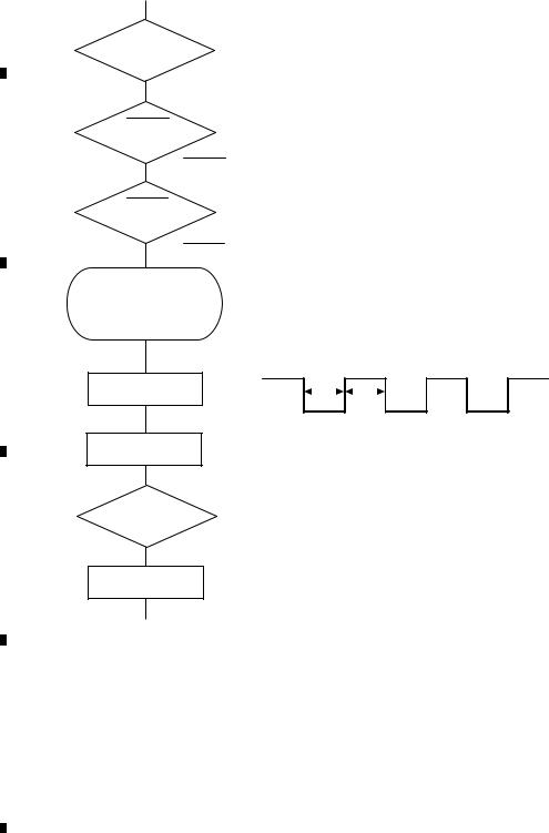
|
1 |
|
2 |
|
3 |
|
4 |
|
5. DIAGNOSIS
5.1 OPERATIONAL FLOWCHART
A
Power ON
VDD = 5 V
Pin 8
BSENS
Pin 36
B |
BSENS = L |
ASENS
Pin 35
ASENS = L
Starts communication with Grille microcomputer.
C
SWVDD <- H
Pin 1
Source keys operative
300 ms
300 ms
In case of the above signal, the communication with Grille microcomputer may fail.
If the time interval is not 300 msec, the oscillator may be defective.
Source ON
D
SYSPW <- H
Pin 15
Completes power-on operation.
(After that, proceed to each source operation)
E
F
16 |
DEH-1100MPB/XN/EW5 |
|
1 |
|
2 |
|
3 |
|
4 |
|
|
|
|
|
|

|
5 |
|
6 |
|
7 |
|
8 |
5.2ERROR CODE LIST
-Error Messages
If a CD is not operative or stopped during operation due to an error, the error mode is turned on and cause(s) of the error is indicated with a corresponding number. This arrangement is intended at reducing nonsense calls from the users and also for facilitating trouble analysis and repair work in servicing.
(1) Basic Indication Method
1)When SERRORM is selected for the CSMOD (CD mode area for the system), error codes are written to DMIN (minutes display area) and DSEC (seconds display area). The same data is written to DMIN and DSEC. DTNO remains in blank as before.
2)Head unit display examples
Depending on display capability of LCD used, display will vary as shown below. xx contains the error number.
|
|
|
8-digit display |
|
6-digit display |
4-digit display |
||||
|
|
|
ERROR-xx |
|
|
ERR-xx |
|
|
E-xx |
|
|
|
|
|
|
|
|
|
|
|
|
(2) Error Code List |
|
|
|
|
|
|
|
|
||
Code |
Class |
Displayed error code |
Description of the code and potential cause(s) |
|
|
|||||
10 |
Electricity |
Carriage Home NG |
CRG can't be moved to inner diameter. |
|
|
|||||
|
|
|
SERVO LSI Com- |
CRG can't be moved from inner diameter. |
|
|
||||
|
|
|
munication Error |
-> Failure on home switch or CRG move mechanism. |
||||||
|
|
|
|
|
Communication error between microcomputer and SERVO LSI. |
|||||
11 |
Electricity |
Focus Servo NG |
Focusing not available. |
|
|
|||||
|
|
|
|
|
-> Stains on rear side of disc or excessive vibrations on REWRITABLE. |
|||||
12 |
Electricity |
Spindle Lock NG |
Spindle not locked. Sub-code is strange (not readable). |
|||||||
|
|
|
Subcode NG |
-> Failure on spindle, stains or damages on disc, or excessive vibrations. |
||||||
|
|
|
|
|
A disc not containing CD-R data is found. |
|
|
|||
|
|
|
|
|
Turned over disc are found, though rarely. |
|
|
|||
|
|
|
|
|
CD signal error. |
|
|
|||
17 |
Electricity |
Setup NG |
AGC protection doesn't work. Focus can be easily lost. |
|||||||
|
|
|
|
|
-> Damages or stains on disc, or excessive vibrations on REWRITABLE. |
|||||
30 |
Electricity |
Search Time Out |
Failed to reach target address. |
|
|
|||||
|
|
|
|
|
-> CRG tracking error or damages on disc. |
|
|
|||
44 |
Electricity |
ALL Skip |
Skip setting for all track. |
|
|
|||||
|
|
|
|
|
(CD-R/RW) |
|
|
|||
50 |
Mechanism |
CD On Mech Error |
Mechanical error during CD ON. |
|
|
|||||
|
|
|
|
|
-> Defective loading motor, mechanical lock and mechanical sensor. |
|||||
A0 |
System |
Power Supply NG |
Power (VD) is ground faulted. |
|
|
|||||
|
|
|
|
|
-> Failure on SW transistor or power supply (failure on connector). |
|||||
Remarks: Mechanical errors are not displayed (because a CD is turned off in these errors). Unreadable TOC does not constitute an error. An intended operation continues in this case. Upper digits of an error code are subdivided as shown below:
1x: Setup relevant errors, 3x: Search relevant errors, Ax: Other errors.
|
|
|
|
DEH-1100MPB/XN/EW5 |
|
|
|
17 |
||
|
5 |
|
6 |
|
|
7 |
|
8 |
|
|
|
|
|
|
|
||||||
A
B
C
D
E
F

|
1 |
|
2 |
|
3 |
|
4 |
|
5.3 CONNECTOR FUNCTION DESCRIPTION
A |
REAR |
|
|
|
|
|
|
OUTPUT |
|
|
|
|
|
|
|
|
|
|
|
|
|
|
|
B |
|
|
|
|
|
|
|
|
ANTENNA |
|
|
|
|
|
WIRED REMOTE |
|
|
|
|
7 |
9 |
|
CONTROL |
|
1 |
3 |
5 |
11 13 |
15 |
||
|
2 |
4 |
6 |
8 |
10 12 14 |
16 |
|
|
|
1 |
FR+ |
9 |
MUTE |
C |
2 |
RR+ |
10 |
NC |
|
|
|
3 |
FR- |
11 |
B.REM |
|
|
4 |
RR- |
12 |
NC |
|
|
5 |
FL+ |
13 |
A.ANT |
|
|
6 |
RL+ |
14 |
ACC |
|
|
7 |
FL- |
15 |
GND |
|
|
8 |
RL- |
16 |
B.UP |
|
|
|
|
|
|
6. SERVICE MODE
6.1 DISPLAY TEST MODE
D

 1. To enter the test mode
Turn on ACC and Backup while pressing the 1 and the 3 buttons together.

 2. To exit from the test mode
Turn off the ACC and Backup.
3. Operation method
E
Change display as follows by pushing the 1 and the 3 buttons together.
All lighting of display
ROM Correction version display
F
18 |
DEH-1100MPB/XN/EW5 |
|
1 |
|
2 |
|
3 |
|
4 |
|
|
|
|
|
|

|
5 |
|
6 |
|
7 |
|
8 |
|
6.2CD TEST MODE
-Flow Chart
|
[Key] |
[4] + [6] + Reset or |
|
|
|
|
|
|
|
|
|
|
|
|
|
|
|
|
|
|
||||
Contents |
[4] + [6] + BU + ACC |
|
|
|
|
|
|
|
|
|
|
|
|
|
|
|
|
|
|
|||||
Test Mode In |
|
|
|
|
|
|
|
|
|
|
|
|
|
|
|
|
|
A |
||||||
|
|
|
|
|
|
|
|
|
|
|
|
|
|
|
|
|
|
|
|
|||||
|
|
|
|
|
|
|
|
|
|
|
|
|
|
|
|
|
|
|
|
|
|
|
||
|
Display |
|
|
|
|
|
|
|
|
|
|
|
|
|
|
|
|
|
|
|
|
|
||
|
|
|
[CD] or [SOURCE] |
|
|
|
|
|
|
|
|
|
|
|
|
|
|
|
|
|
|
|||
|
|
|
Source On |
|
|
|
|
|
|
|
|
|
|
|
|
|
|
|
|
|
|
|||
|
|
|
TRK |
MIN |
SEC |
|
|
|
|
|
|
|
|
|
|
|
|
|
|
|
|
|
|
|
|
|
|
[BAND] |
|
[3] |
|
|
[2] |
|
|
[4] |
|
|
|
|
|
|
|
|
|
|
|
||
|
|
|
Power On |
Power On |
RF AMP |
*1 |
SPINDLE *9 |
|
|
|
|
|
|
|
|
|
||||||||
|
|
|
(T.Offset is adjusted) |
(T.Offset is not adjusted) |
Gain switching |
Speed switching |
|
|
|
|
|
|
|
|
|
|||||||||
|
|
|
TRK |
MIN |
SEC |
TRK |
MIN |
SEC |
TRK |
MIN |
SEC |
TRK |
MIN |
SEC |
|
|
|
|
|
|
|
|
|
|
|
|
|
00 |
00 |
00 |
99 |
99 |
99 |
GG |
GG |
GG |
SP |
SP |
SP |
|
|
|
|
|
|
|
|
|
|
[BAND] |
|
|
[3] |
|
|
[6] |
|
|
[1] |
|
|
[>] |
|
|
[<] |
|
|
[2] |
|
|
[5] |
|
B |
|
Power Off |
Focus Close |
Focus Mode switching |
Tracking Servo |
|
CRG + |
|
|
CRG - |
|
Self-adjusting |
|
|||||||||||||
|
|
|
*8 |
Gop Mode |
*10 |
|||||||||||||||||||
|
|
|
S curve check |
|
|
*2 |
|
Close |
|
|
|
*8 |
|
|
|
switching *3 |
||||||||
|
|
|
|
|
|
|
|
|
|
|
|
Gop Mode switching |
||||||||||||
TRK |
MIN |
SEC |
TRK |
MIN |
SEC |
TRK |
MIN |
SEC |
00 |
00 00 |
00 |
00 |
00 |
00 |
00 |
00 |
TRK |
MIN |
SEC |
|||||
TRK |
MIN |
SEC |
||||||||||||||||||||||
|
|
|
91 |
91 |
91 |
0X |
0X |
0X |
or 99 99 |
99 |
or 99 99 |
99 |
or 99 99 |
99 |
?? |
?? |
?? |
|||||||
|
|
|
OL |
OL |
OL |
|||||||||||||||||||
|
|
|
|
|
|
|
|
|
|
|
|
|
|
|
|
|
|
|
|
|
||||
[BAND] |
|
|
[1] |
|
|
[6] |
|
|
[3] |
|
|
[>] |
|
|
[<] |
|
|
[2] |
|
|
|
|
|
|
Power Off |
T.Close & AGC |
|
T.Close |
|
RF AGC / |
|
|
CRG + |
|
|
CRG - |
|
T.Balance adjustment / |
|
|
|
||||||||
|
|
|
Applicableservomechanism |
Applicableservomechanism |
RF AGC coefficient display |
|
|
|
|
|
|
T.BAL coefficient display |
|
|
|
|||||||||
TRK |
MIN |
SEC |
TRK |
MIN |
SEC |
TRK |
MIN |
SEC |
TRK |
MIN |
SEC |
8X 8X |
8X |
8X 8X |
8X |
TRK |
MIN |
SEC |
|
|
|
|||
|
|
|
?tr ?min ?sec |
?tr ?min ?sec |
?? |
?? |
?? |
or 9X 9X |
9X |
or 9X 9X |
9X |
?? |
?? |
?? |
|
|
|
|||||||
[BAND] |
|
|
[1] |
|
|
[3] |
|
|
[6] |
|
*5 |
[>] |
|
|
[<] |
|
|
[2] |
|
|
|
|
|
|
Power Off |
F,T,RF AGC*7 |
F,T AGC / F.Bias |
CRG/TR jump |
CRG/TR Jump + |
CRG/TR Jump - |
Tracking Open |
|
|
|
|||||||||||||||
|
|
|
F.Bias display switching |
|
RF AGC |
|
value switching |
|
|
*4 |
|
|
*4 |
|
|
|
|
|
|
|||||
TRK |
MIN |
SEC |
TRK |
MIN |
SEC |
TRK |
MIN |
SEC |
TRK |
MIN |
SEC |
TRK |
MIN |
SEC |
TRK |
MIN |
SEC |
8X 8X |
8X |
|
|
|
||
|
|
|
?? |
?? |
?? |
?tr ?min ?sec |
?tr ?min ?sec |
?tr ?min ?sec |
?tr ?min ?sec |
or 9X 9X |
9X |
|
|
C |
||||||||||
|
|
|
|
|
|
|
|
|
|
|
|
|
|
|
|
|
|
|
|
|
|
|
||
|
|
|
|
|
|
|
|
|
|
|
|
|
|
|
|
|
*6 |
|
|
|
|
|
|
|
[BAND] |
|
|
|
|
|
|
|
|
|
|
|
|
|
|
[2] |
|
|
|
|
|
|
|
|
|
Power Off |
|
|
|
|
|
|
|
|
|
|
|
|
Tracking Open |
|
|
|
|
|
|
|||||
TRK |
MIN |
SEC |
|
|
|
|
|
|
|
|
|
|
|
|
8X 8X |
8X |
|
|
|
|
|
|
||
|
|
|
|
|
|
|
|
|
|
|
|
|
|
|
or 9X 9X |
9X |
|
|
|
|
|
|
||
*1) |
TYP |
→ |
|
+ 6 dB |
|
→ |
|
+ 12 dB |
|
|
|
[Key] |
|
|
|
Operation |
|
|
|
|||||
TRK |
MIN |
SEC |
|
TRK06MIN06SEC06 |
TRK12MIN12SEC12 |
|
|
|
|
|
Test Mode |
|
|
|
||||||||||
|
|
|
|
|
|
|
|
|
|
|
|
|
|
|
|
|
|
[BAND] |
Power On/Off |
|
|
|
|
|
||||
|
*2) Focus Close → S Curve check setting → F EQ measurement setting |
|
[>] |
CRG + / TR Jump + |
|
|
|
|
|
|||||||||||||||||||
|
|
|
(Direction of the external surface) |
|
|
|
|
|||||||||||||||||||||
|
TRK00MIN00SEC00 |
TRK01MIN01SEC01 |
|
TRK02MIN02SEC02 |
|
[<] |
CRG - / TR Jump - |
|
|
|
D |
|||||||||||||||||
|
(TRK99MIN99SEC99) |
|
|
|
|
|
|
|
|
|
|
|
|
|
(Direction of the internal surface) |
|
|
|||||||||||
|
|
|
|
|
|
|
|
|
|
|
|
|
|
|
|
|
|
[1] |
T. CLS & AGC & Applicable servomechanism / |
|
|
|||||||
|
*3) F.Offset Display → RF.Offset → T.Offset Display → Switch to the |
|
|
AGC,AGC display setting |
|
|
|
|
|
|||||||||||||||||||
|
|
[2] |
RF Gain switching / Offset adjustment display / |
|
|
|||||||||||||||||||||||
|
|
|
|
|
|
|
|
|
|
|
order of the original display |
|
|
|
||||||||||||||
|
|
|
|
|
|
|
|
|
|
|
|
|
T.Balance adjustment / T. Open |
|
|
|
|
|||||||||||
|
|
|
|
|
|
|
|
|
|
|
|
|
|
|
|
|
|
|
|
|
|
|
||||||
|
|
|
|
|
|
|
|
|
|
|
|
|
|
|
|
|
|
[3] |
F. Close,S Curve / Rough Servo and RF AGC / |
|
|
|||||||
|
|
|
|
|
|
|
|
|
|
|
|
|
|
|
|
|
|
|
|
|||||||||
|
|
|
|
|
|
|
|
|
|
|
|
|
|
|
|
|
|
|
|
|||||||||
|
*4) 1TR/4TR/10TR/32TR/100TR |
|
|
|
|
|
|
|
|
|
F,T,RF AGC |
|
|
|
|
|
||||||||||||
|
|
|
|
|
|
|
|
|
|
|
|
|
|
|
||||||||||||||
|
|
|
|
|
|
|
|
|
[4] |
SPDL 1X/2X switching |
|
|
|
|
|
|||||||||||||
*5) |
Single |
→ 4TR |
→ 10TR → 32TR → |
100TR → CRG Move |
|
|
|
|
|
|
||||||||||||||||||
|
|
As for the double speed(2x), audio output cannot be |
|
|
||||||||||||||||||||||||
|
9x(8x):91(81) |
92(82) |
93(83) |
|
94(84) |
95(85) |
|
96(86) |
|
|
|
|
|
|
||||||||||||||
|
|
|
|
|
|
|
supported. |
|
|
|
|
|
|
|
|
|||||||||||||
|
|
|
|
|
|
|
|
|
|
|
|
|
|
|
|
|
|
|
|
|
|
|
|
|
|
|
||
|
*6) Only at the time of CRG move, 100TR jump |
|
|
|
|
|
|
[5] |
Error Rate measurement |
|
|
|
|
|
||||||||||||||
|
|
|
|
|
|
|
|
|
|
ON : ERR 30Counts Start |
|
|
||||||||||||||||
|
|
|
|
|
|
|
|
|
|
|
|
|
|
|
|
|
|
|
|
|
|
|
||||||
|
*7) TRK/MIN/SEC → F.AGC → T.AGC Gain → F.Bias → RF AGC |
|
|
|
|
BER display data[%] |
E |
|||||||||||||||||||||
|
|
[6] |
F. Mode switching / Tracking Close / CRG•TR |
|||||||||||||||||||||||||
|
|
|||||||||||||||||||||||||||
|
|
|
|
|
|
|
|
|
|
|
|
|
|
|
|
|
|
|
|
|||||||||
|
|
|
|
|
|
|
|
|
|
|
|
|
|
|
|
|
|
|
Jump Switching |
|
|
|
|
|
||||
|
*8) CRG motor voltage = 2 [V] |
|
|
|
|
|
|
|
|
|
|
|
|
|
|
|
|
|
|
|
||||||||
*9) |
|
TYP (1X) |
→ |
2X |
|
→ |
1X |
*10) |
OFF(TYP) → |
FORCUS |
→ |
TRACKING |
|
|
||||||||||||||
|
|
TRK MIN |
|
SEC |
|
TRK22MIN22SEC22 |
TRK11MIN11SEC11 |
TRK MIN |
SEC |
TRK70MIN70SEC70 |
TRK71MIN71SEC71 |
|
|
|||||||||||||||
|
|
|
|
|
|
|||||||||||||||||||||||
|
|
• As for the double speed (2x), audio output cannot be supported |
|
|
|
|
|
|
|
|
|
|
|
|||||||||||||||
|
|
|
|
|
|
|
|
|
|
|
|
|
||||||||||||||||
|
|
|
|
|
|
|
|
|
|
|
|
|
||||||||||||||||
|
*) • After the [Eject] key is pressed keys other than the [Eject] key should not be pressed, until disc ejection is complete. |
|
|
|||||||||||||||||||||||||
|
• When the key [2] or [3] is pressed during the Focus Search, the power supply should be immediately turned off (otherwise the lens |
|
|
|||||||||||||||||||||||||
|
|
sticks to Wall, causing the actuator to be damaged). |
|
|
|
|
|
|
|
|
|
|
|
|
|
|
F |
|||||||||||
|
• In the case of TR jump other than to 100TR, the function shall continue to be processed even if the TR jump key is released. As for |
|
||||||||||||||||||||||||||
|
|
|
||||||||||||||||||||||||||
|
|
the CRG Move and 100TR Jump, the mechanism shall be set to the Tracking Close mode when the key is released. |
|
|
||||||||||||||||||||||||
|
• When the power is turned on/off the jump mode is reset to the Single TR (91) while the gain of the RFAMP is reset to 0 dB. At the |
|
|
|||||||||||||||||||||||||
|
|
same time all the self-adjusting values shall return to the default setting. |
|
|
|
|
|
|
|
|
|
|
||||||||||||||||
|
|
|
|
|
|
|
|
|
|
|
|
|
|
|
|
|
|
|
|
|
|
|
|
|
|
|
|
|
|
|
|
|
|
|
|
|
|
|
|
|
|
|
DEH-1100MPB/XN/EW5 |
|
|
|
|
|
|
|
19 |
|
|||||
|
|
|
|
5 |
|
|
|
|
|
|
|
6 |
|
|
|
|
|
|
7 |
|
|
|
|
8 |
|
|
||
|
|
|
|
|
|
|
|
|
|
|
|
|
|
|
|
|
|
|
|
|
|
|||||||
Loading...