


 Loading...
ORDER NO.
CRT4279
DEH-P510UB/XN/UC
CD RECEIVER
DEH-P510UB/XN/UC
DEH-P5100UB/XN/UC
DEH-P5150UB/XN/ES
DEH-P5150UB/XN/ES1
DEH-P5190UB/XN/ID
This service manual should be used together with the following manual(s):
Model No. |
Order No. |
Mech.Module |
|
|
|
Remarks |
|||||||||
|
|
|
|
|
|
|
|
|
|
|
|
|
|
|
|
CX-3240 |
CRT4050 |
S10.5COMP2-iPod/USB |
CD Mech. Module : Circuit Descriptions, Mech. Descriptions, Disassembly |
||||||||||||
|
|
|
|
|
|
|
|
|
|
|
|
|
|
|
|
|
|
|
|
|
|
|
|
|
|
|
|
|
|
|
|
|
|
|
|
|
|
|
|
|
|
|
|
|
|
|
|
|
|
|
|
|
|
|
|
|
|
|
|
|
|
|
|
|
|
|
|
|
|
|
|
|
|
|
|
|
|
|
|
|
|
|
|
|
|
|
|
|
|
|
|
|
|
|
|
|
|
|
|
|
|
|
|
|
|
|
|
|
|
|
|
For details, refer to "Important Check Points for Good Servicing".
PIONEER CORPORATION 4-1, Meguro 1-chome, Meguro-ku, Tokyo 153-8654, Japan PIONEER ELECTRONICS (USA) INC. P.O. Box 1760, Long Beach, CA 90801-1760, U.S.A. PIONEER EUROPE NV Haven 1087, Keetberglaan 1, 9120 Melsele, Belgium
PIONEER ELECTRONICS ASIACENTRE PTE. LTD. 253 Alexandra Road, #04-01, Singapore 159936
 PIONEER CORPORATION 2009
K-ZZZ. JAN. 2009 Printed in Japan

|
1 |
|
2 |
|
3 |
|
4 |
|
SAFETY INFORMATION
CAUTION
AThis service manual is intended for qualified service technicians; it is not meant for the casual do-it-yourselfer. Qualified technicians have the necessary test equipment and tools, and have been trained to properly and safety repair complex products such as those covered by this manual.
Improperly performed repairs can adversely affect the safety and reliability of the product and may void the warranty. If you are not qualified to perform the repair of this product properly and safety, you should not risk trying to do so and refer the repair to a qualified service technician.
WARNING
This product contains certain electrical parts contain chemicals which are known to the State of
California to cause cancer, birth defects or other reproductive harm.
Health & Safety Code Section 25249.6 - Proposition 65
B
Where in a manufacturer’s service documentation, for example in circuit diagrams or lists
of components, a symbol is used to indicate that a specific component shall be replaced only by the component specified in that documentation for safety reasons, the following symbol shall be used:
-Safety Precautions for those who Service this Unit.
When checking or adjusting the emitting power of the laser diode exercise caution in order to get safe, reliable results.
Caution:
C
1.During repair or tests, minimum distance of 13 cm from the focus lens must be kept.
2.During repair or tests, do not view laser beam for 10 seconds or longer.
CAUTION:
USE OF CONTROLS OR ADJUSTMENTS OR PERFORMANCE OF PROCEDURES OTHER THAN THOSE SPECIFIED HEREIN MAY RESULT IN HAZARDOUS RADIATION EXPOSURE.
CAUTION
CLASS 1M INVISIBLE LASER RADIATION WHEN OPEN. DO NOT VIEW DIRECTLY WITH OPTICAL INSTRUMENTS
D
CAUTION
Danger of explosion if battery is incorrectly replaced.
Replaced only with the same or equivalent type recommended by the manufacture.
Discord used batteries according to the manufacture's instructions.
E
F
2 |
DEH-P510UB/XN/UC |
|
1 |
|
2 |
|
3 |
|
4 |
|
|
|
|
|
|
|
5 |
|
6 |
|
7 |
|
8 |
[Important Check Points for Good Servicing]
In this manual, procedures that must be performed during repairs are marked with the below symbol. Please be sure to confirm and follow these procedures.
1. Product safety
Please conform to product regulations (such as safety and radiation regulations), and maintain a safe servicing environment by following the safety instructions described in this manual.
1 Use specified parts for repair.
Use genuine parts. Be sure to use important parts for safety.
2 Do not perform modifications without proper instructions.
Please follow the specified safety methods when modification(addition/change of parts) is required due to interferences such as radio/TV interference and foreign noise.
3 Make sure the soldering of repaired locations is properly performed.
When you solder while repairing, please be sure that there are no cold solder and other debris.
Soldering should be finished with the proper quantity. (Refer to the example)
4 Make sure the screws are tightly fastened.
Please be sure that all screws are fastened, and that there are no loose screws.
5 Make sure each connectors are correctly inserted.
Please be sure that all connectors are inserted, and that there are no imperfect insertion.
6 Make sure the wiring cables are set to their original state.
Please replace the wiring and cables to the original state after repairs.
In addition, be sure that there are no pinched wires, etc.
7Make sure screws and soldering scraps do not remain inside the product. Please check that neither solder debris nor screws remain inside the product.
8There should be no semi-broken wires, scratches, melting, etc. on the coating of the power cord.
Damaged power cords may lead to fire accidents, so please be sure that there are no damages.
If you find a damaged power cord, please exchange it with a suitable one.
9 There should be no spark traces or similar marks on the power plug.
When spark traces or similar marks are found on the power supply plug, please check the connection and advise on secure connections and suitable usage. Please exchange the power cord if necessary.
a Safe environment should be secured during servicing.
When you perform repairs, please pay attention to static electricity, furniture, household articles, etc. in order to prevent injuries. Please pay attention to your surroundings and repair safely.
2. Adjustments
 To keep the original performance of the products, optimum adjustments and confirmation of characteristics within specification. Adjustments should be performed in accordance with the procedures/instructions described in this manual.
A
B
C
D
3. Lubricants, Glues, and Replacement parts
Use grease and adhesives that are equal to the specified substance.
Make sure the proper amount is applied.
E
4. Cleaning
For parts that require cleaning, such as optical pickups, tape deck heads, lenses and mirrors used in projection monitors, proper cleaning should be performed to restore their performances.
5. Shipping mode and Shipping screws
To protect products from damages or failures during transit, the shipping mode should be set or the shipping screws should be installed before shipment. Please be sure to follow this method especially if it is specified in this manual.
F
|
|
|
|
DEH-P510UB/XN/UC |
|
|
|
3 |
|
||
|
5 |
|
6 |
|
|
7 |
|
8 |
|
|
|
|
|
|
|
|
|
||||||

|
|
1 |
|
|
2 |
|
|
3 |
|
4 |
|
|
|
CONTENTS |
|
|
|
|
|
|
|
||
|
|
SAFETY INFORMATION..................................................................................................................................... |
|
|
|
|
2 |
|
|||
|
|
1. SERVICE PRECAUTIONS ............................................................................................................................... |
|
|
|
|
5 |
|
|||
A |
1.1 SERVICE PRECAUTIONS......................................................................................................................... |
|
|
|
|
5 |
|
||||
1.2 NOTES ON SOLDERING |
|
|
|
|
5 |
|
|||||
|
|
|
|
|
|
|
|||||
|
|
2. SPECIFICATIONS ............................................................................................................................................ |
|
|
|
|
6 |
|
|||
|
|
2.1 SPECIFICATIONS...................................................................................................................................... |
|
|
|
|
6 |
|
|||
|
|
2.2 DISC/CONTENT FORMAT ........................................................................................................................ |
|
|
|
|
8 |
|
|||
|
|
2.3 PANEL FACILITIES .................................................................................................................................... |
|
|
|
|
9 |
|
|||
|
|
2.4 CONNECTION DIAGRAM |
|
|
|
|
13 |
|
|||
|
|
|
|
|
|
|
|||||
|
|
........................................................................................................................3. BASIC ITEMS FOR SERVICE |
|
|
|
|
18 |
|
|||
|
|
3.1 CHECK POINTS AFTER SERVICING..................................................................................................... |
|
18 |
|
||||||
|
|
3.2 PCB LOCATIONS .................................................................................................................................... |
|
|
|
|
19 |
|
|||
|
|
3.3 JIGS LIST ................................................................................................................................................ |
|
|
|
|
20 |
|
|||
|
|
3.4 CLEANING............................................................................................................................................... |
|
|
|
|
20 |
|
|||
B |
4. BLOCK DIAGRAM.......................................................................................................................................... |
|
|
|
|
22 |
|
||||
|
|
5. DIAGNOSIS.................................................................................................................................................... |
|
|
|
|
24 |
|
|||
|
|
5.1 OPERATIONAL FLOWCHART ................................................................................................................ |
|
|
|
|
24 |
|
|||
|
|
5.2 ERROR CODE LIST ................................................................................................................................ |
|
|
|
|
25 |
|
|||
|
|
5.3 CONNECTOR FUNCTION DESCRIPTION............................................................................................. |
|
27 |
|
||||||
|
|
6. SERVICE MODE ............................................................................................................................................ |
|
|
|
|
28 |
|
|||
|
|
6.1 DISPLAY TEST MODE |
|
|
|
|
28 |
|
|||
|
|
|
|
|
|
|
|||||
|
|
|
|
|
|
|
|||||
|
|
6.2 CD TEST MODE...................................................................................................................................... |
|
|
|
|
31 |
|
|||
|
|
7. DISASSEMBLY............................................................................................................................................... |
|
|
|
|
32 |
|
|||
|
|
8. EACH SETTING AND ADJUSTMENT ........................................................................................................... |
|
|
|
|
35 |
|
|||
|
|
8.1 CD ADJUSTMENT................................................................................................................................... |
|
|
|
|
35 |
|
|||
C |
8.2 CHECKING THE GRATING AFTER CHANGING THE PICKUP UNIT |
.................................................... |
36 |
|
|||||||
8.3 PCL OUTPUT CONFIRMATION |
|
|
|
|
38 |
|
|||||
|
|
|
|
|
|
|
|||||
|
|
9. EXPLODED VIEWS AND PARTS LIST.......................................................................................................... |
|
|
|
|
40 |
|
|||
|
|
9.1 PACKING ................................................................................................................................................. |
|
|
|
|
40 |
|
|||
|
|
9.2 EXTERIOR(1) .......................................................................................................................................... |
|
|
|
|
42 |
|
|||
|
|
9.3 EXTERIOR(2) .......................................................................................................................................... |
|
|
|
|
44 |
|
|||
|
|
9.4 CD MECHANISM MODULE..................................................................................................................... |
|
|
|
|
46 |
|
|||
|
|
|
|
|
|
|
|||||
|
|
10. SCHEMATIC DIAGRAM |
|
|
|
|
48 |
|
|||
|
|
|
|
|
|
|
|||||
|
|
10.1 TUNER AMP ASSY(GUIDE PAGE) |
....................................................................................................... |
|
|
|
48 |
|
|||
|
|
10.2 KEYBOARD UNIT.................................................................................................................................. |
|
|
|
|
54 |
|
|||
|
|
10.3 CD MECHANISM MODULE(GUIDE PAGE) .......................................................................................... |
|
56 |
|
||||||
|
|
10.4 WAVEFORMS ........................................................................................................................................ |
|
|
|
|
62 |
|
|||
D |
11. PCB CONNECTION DIAGRAM ................................................................................................................... |
|
|
|
|
66 |
|
||||
11.1 TUNER AMP ASSY |
|
|
|
|
66 |
|
|||||
|
|
|
|
|
|
|
|||||
|
|
11.2 KEYBOARD UNIT.................................................................................................................................. |
|
|
|
|
70 |
|
|||
|
|
11.3 CD CORE UNIT(S10.5iPod-Code3) ...................................................................................................... |
|
72 |
|
||||||
|
|
12. ELECTRICAL PARTS LIST .......................................................................................................................... |
|
|
|
|
74 |
|
|||
|
|
|
|
|
|
|
|
|
|
|
|
|
|
|
|
|
|
|
|
|
|
|
|
E
F
4 |
DEH-P510UB/XN/UC |
|
1 |
|
2 |
|
3 |
|
4 |
|
|
|
|
|
|

|
5 |
|
6 |
|
7 |
|
8 |
1. SERVICE PRECAUTIONS
1.1SERVICE PRECAUTIONS
1.You should conform to the regulations governing the product (safety, radio and noise, and other regulations), and should keep the safety during servicing by following the safety instructions described in this manual.
2.Before disassembling the unit, be sure to turn off the power. Unplugging and plugging the connectors during power-on mode may damage the ICs inside the unit.
3.To protect the pickup unit from electrostatic discharge during servicing, take an appropriate treatment (shorting-solder) by referring to "the DISASSEMBLY".
4.After replacing the pickup unit, be sure to check the grating.
5.Be careful in handling ICs. Some ICs such as MOS type are so fragile that they can be damaged by electrostatic induction.
6.Mechanism cover (Sheet: CNM9404) is NOT reusable. If you remove it, please replace it with the new one.
A
B
C
1.2 NOTES ON SOLDERING
 For environmental protection, lead-free solder is used on the printed circuit boards mounted in this unit.
Be sure to use lead-free solder and a soldering iron that can meet specifications for use with lead-free solders for repairs accompanied by reworking of soldering.
 Compared with conventional eutectic solders, lead-free solders have higher melting points, by approximately 40
  C. Therefore, for lead-free soldering, the tip temperature of a soldering iron must be set to around 373
  C in general, although the temperature depends on the heat capacity of the PC board on which reworking is required and the weight of the tip of the soldering iron.
Compared with eutectic solders, lead-free solders have higher bond strengths but slower wetting times and higher melting temperatures (hard to melt/easy to harden).
The following lead-free solders are available as service parts:
 Parts numbers of lead-free solder:
GYP1006 1.0 in dia.
GYP1007 0.6 in dia.
GYP1008 0.3 in dia.
D
E
F
|
|
|
|
DEH-P510UB/XN/UC |
|
|
|
5 |
|
||
|
5 |
|
6 |
|
|
7 |
|
8 |
|
|
|
|
|
|
|
|
|
||||||
|
1 |
|
2 |
|
3 |
|
4 |
|
2. SPECIFICATIONS
2.1 SPECIFICATIONS
A
DEH-P510UB/XN/UC, DEH-P5100UB/XN/UC
General
Power source.......................... |
14.4 V DC (10.8 V to 15.1 V |
|
|
allowable) |
|
Grounding system................ |
Negative type |
|
Max. current consumption |
|
|
B ............................................... |
10.0 A |
|
6.0 mA or less |
||
Backup current ....................... |
WMA decoding format ....... |
Ver. 7, 7.1, 8, 9, 10, 11 (2ch |
|
audio) |
|
(Windows Media Player) |
AAC decoding format........... |
MPEG-4 AAC (iTunes en- |
|
coded only) (.m4a) |
|
(Ver. 7.7 and earlier) |
WAV signal format ................ |
Linear PCM & MS ADPCM |
|
(Non-compressed) |
|
Dimensions (W × H × D): |
|
|
|
DIN |
|
|
|
Chassis .................. |
178 mm × 50 mm × 162 |
|
|
|
mm |
|
|
|
(7 in. × 2 in. × 6-3/8 in.) |
|
|
|
||
|
Nose ....................... |
188 mm × 58 mm × 17 mm |
|
|
|
(7-3/8 in.× 2-1/4 in.× 5/8 in.) |
|
|
D |
|
|
|
Chassis .................. |
178 mm × 50 mm × 162 |
|
C |
mm |
||
(7 in.× 2 in.× 6-3/8 in.) |
|||
|
|
||
|
Nose ....................... |
170 mm × 48 mm × 17 mm |
|
|
|
(6-3/4 in.× 1-7/8 in.× 5/8 in.) |
|
|
Weight ..................................... |
1.5 kg(3.3 lbs) |
|
Audio
|
|
Maximum power output ...... |
50 W × 4 |
|
|
|
|
|
|
50 W × 2/4 |
+ 70 W × 1/2 |
||
|
|
|
(for subwoofer) |
|
||
|
|
Continuous power output .. |
22 W × 4 (50 Hz to 15 000 |
|||
|
|
|
Hz, 5 % THD, 4 |
load, both |
||
D |
|
channels driven) |
|
|||
|
|
Load impedance ................... |
4 |
to 8 |
× 4 |
|
|
|
|
4 |
to 8 |
× 2 + 2 |
× 1 |
|
|
Preout max output level ...... |
4 V |
|
|
|
|
|
Equalizer (7-Band Graphic Equalizer): |
|
|
||
|
|
Frequency....................... |
50/125/315/800/2k/5k/12.5k |
|||
|
|
|
Hz |
|
|
|
|
|
|
|
|
|
|
|
|
..................................Gain |
±12 dB |
|
|
|
|
|
HPF: |
|
|
|
|
|
|
Frequency...................... |
50/63/80/100/125 Hz |
|||
|
|
Slope............................... |
–12 dB/oct |
|
|
|
|
|
Subwoofer (mono): |
|
|
|
|
E |
Frequency....................... |
50/63/80/100/125 Hz |
||||
|
|
Slope................................ |
–18 dB/oct |
|
|
|
|
|
Gain ................................. |
+6 dB to –24 dB |
|
||
|
|
Phase .............................. |
Normal/Reverse |
|
||
|
|
Bass boost: |
|
|
|
|
|
|
Gain ................................. |
+12 dB to 0 dB |
|
||
|
|
|
|
|
|
|
CD player
|
System ..................................... |
Compact disc audio system |
|
|
Usable discs .......................... |
Compact disc |
|
|
Signal-to-noise ratio............. |
94 dB (1 kHz) (IHF-A net- |
|
F |
|
work) |
|
Number of channels |
2 (stereo) |
||
|
|||
|
MP3 decoding format .......... |
MPEG-1 & 2 Audio Layer 3 |
USB
USB standard specification |
|
.............................................. |
USB 2.0 full speed |
Maximum current supply ... |
500 mA |
Minimum memory capacity |
|
............................................... |
256 MB |
USB Class............................... |
MSC(Mass Storage Class) |
File system.............................. |
FAT16, FAT32 |
MP3 decoding format .......... |
MPEG-1 & 2 Audio Layer 3 |
WMA decoding format ....... |
Ver. 7, 7.1, 8, 9, 10, 11 (2ch |
|
audio) |
|
(Windows Media Player) |
AAC decoding format........... |
MPEG-4 AAC (iTunes en- |
|
coded only) (.m4a) |
|
(Ver. 7.7 and earlier) |
WAV signal format ................ |
Linear PCM & MS ADPCM |
|
(Non-compressed) |
FM tuner
Frequency range.................... |
87.9 MHz to 107.9 MHz |
Usable sensitivity................... |
9 dBf(0.7 μV/75 , mono, |
|
S/N: 30 dB) |
Signal-to-noise ratio............. |
72 dB (IHF-A network) |
AM tuner
Frequency range................... |
530 kHz to 1 710 kHz (10 |
|
kHz) |
Usable sensitivity.................. |
25 μV (S/N: 20 dB) |
Signal-to-noise ratio............. |
62 dB (IHF-A network) |
CEA2006 Specifications
Power output ......................... |
14 W RMS × 4 Channels (4 |
|
and 1 % THD+N) |
S/N ratio .................................. |
91 dBA (reference: 1 W into |
|
4 ) |
 Note
Note
Specifications and the design are subject to modifications without notice due to improvements.
6 |
DEH-P510UB/XN/UC |
|
1 |
|
2 |
|
3 |
|
4 |
|
|
|
|
|
|
|
5 |
|
6 |
|
7 |
|
8 |
|
A
DEH-P5150UB/XN/ES, DEH-P5150UB/XN/ES1, DEH-P5190UB/XN/ID
General
Power source.......................... |
14.4 V DC (12.0 V to 14.4 V |
|||
|
allowable) |
|
|
|
Grounding system................. |
Negative type |
|
||
Max. current consumption |
|
|
|
|
............................................... |
10.0 A |
|
|
|
Backup current ....................... |
6.0 mA or less |
|
||
Dimensions (W × H × D): |
|
|
|
|
DIN |
|
|
|
|
Chassis .................. |
178 mm × 50 mm × 162 |
|||
|
mm |
|
|
|
Nose ....................... |
188 mm × 58 mm × 17 mm |
|||
D |
|
|
|
|
Chassis .................. |
178 mm × 50 mm × 162 |
|||
|
mm |
|
|
|
Nose ........................ |
170 mm × 48 mm × 17 mm |
|||
Weight ..................................... |
1.5 kg |
|
|
|
Audio |
|
|
|
|
Maximum power output ...... |
50 W × 4 |
|
|
|
|
50 W × 2/4 |
+ 70 W × 1/2 |
||
|
(for subwoofer) |
|
||
Continuous power output .. |
22 W × 4 (50 Hz to 15 000 |
|||
|
Hz, 5 % THD, 4 |
load, both |
||
|
channels driven) |
|
||
Load impedance ................... |
4 |
to 8 |
× 4 |
|
|
4 |
to 8 |
× 2 + 2 |
× 1 |
Preout max output level ....... |
4 V |
|
|
|
Equalizer (7-Band Graphic Equalizer): |
|
|
||
Frequency....................... |
50/125/315/800/2k/5k/12.5k |
|||
|
Hz |
|
|
|
Gain .................................. |
±12 dB |
|
|
|
HPF: |
|
|
|
|
Frequency....................... |
50/63/80/100/125 Hz |
|||
Slope................................ |
–12 dB/oct |
|
|
|
Subwoofer (mono): |
|
|
|
|
Frequency....................... |
50/63/80/100/125 Hz |
|||
Slope ................................ |
–18 dB/oct |
|
|
|
Gain .................................. |
+6 dB to –24 dB |
|
||
Phase .............................. |
Normal/Reverse |
|
||
Bass boost: |
|
|
|
|
Gain .................................. |
+12 dB to 0 dB |
|
||
CD player |
|
|
|
|
System ..................................... |
Compact disc audio system |
|||
Usable discs .......................... |
Compact disc |
|
||
Signal-to-noise ratio............. |
94 dB (1 kHz) (IEC-A net- |
|||
|
work) |
|
|
|
Number of channels ............ |
2 (stereo) |
|
|
|
MP3 decoding format .......... |
MPEG-1 & 2 Audio Layer 3 |
|||
WMA decoding format ....... |
Ver. 7, 7.1, 8, 9, 10, 11 (2ch |
|||
|
audio) |
|
|
|
|
(Windows Media Player) |
|||
AAC decoding format........... |
MPEG-4 AAC (iTunes en- |
|
coded only) (.m4a) |
|
(Ver. 7.7 and earlier) |
WAV signal format ................ |
Linear PCM & MS ADPCM |
|
(Non-compressed) |
USB
USB standard specification |
|
.............................................. |
USB 2.0 full speed |
Maximum current supply ... |
500 mA |
Minimum memory capacity |
|
.............................................. |
256 MB |
USB Class.............................. |
MSC (Mass Storage Class) |
File system............................. |
FAT16, FAT32 |
MP3 decoding format ......... |
MPEG-1 & 2 Audio Layer 3 |
WMA decoding format ....... |
Ver. 7, 7.1, 8, 9, 10, 11 (2ch |
|
audio) |
|
(Windows Media Player) |
AAC decoding format........... |
MPEG-4 AAC (iTunes en- |
|
coded only) (.m4a) |
|
(Ver. 7.7 and earlier) |
WAV signal format ................ |
Linear PCM & MS ADPCM |
|
(Non-compressed) |
FM tuner
Frequency range................... |
87.5 MHz to 108.0 MHz |
Usable sensitivity.................. |
9 dBf (0.7 μV/75 , mono, |
|
S/N: 30 dB) |
Signal-to-noise ratio............. |
72 dB (IEC-A network) |
AM tuner
Frequency range................... |
531 kHz to 1 602 kHz (9 kHz) |
|
530 kHz to 1 640 kHz (10 |
|
kHz) |
Usable sensitivity.................. |
25 μV (S/N: 20 dB) |
Signal-to-noise ratio............. |
62 dB (IEC-A network) |
Infrared remote control
Wavelength............................. |
940 nm ±50 nm |
Output ...................................... |
typ; 12 mw/sr per Infrared |
|
LED |
|
(ES, ES1) |
 Note
Note
Specifications and the design are subject to modifications without notice due to improvements.
|
|
|
|
DEH-P510UB/XN/UC |
|
|
|
7 |
||
|
5 |
|
6 |
|
|
7 |
|
8 |
|
|
|
|
|
|
|
||||||
B
C
D
E
F

|
1 |
|
2 |
|
3 |
|
4 |
|
2.2 DISC/CONTENT FORMAT
A
DEH-P510UB/XN/UC, DEH-P5100UB/XN/UC
B
C
D
E
F
8 |
DEH-P510UB/XN/UC |
|
1 |
|
2 |
|
3 |
|
4 |
|
|
|
|
|
|
|
5 |
|
6 |
|
7 |
|
8 |
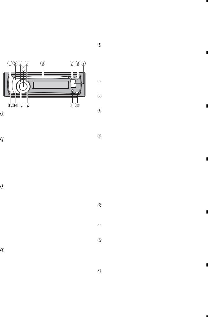
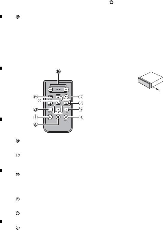
2.3 PANEL FACILITIES
DEH-P510UB/XN/UC, DEH-P5100UB/XN/UC
What ’s what
Head unit
SRC/OFF button
This unit is turned on by selecting a source. Press to cycle through all the available sources.
 /LIST button
Press to display the disc title list, track title list, folder list, file list or preset channel list depending on the source.
Press and hold to switch to link play mode while using an iPod.
For details, refer toPlaying songs related to the currently playing song.
S.Rtrv/SAT MODE button
Press to switch advanced sound retriever settings.
For details, refer toUsing advanced sound retriever.
When XM tuner or SIRIUS tuner is selected as the source, press to change the channel select mode.
When SIRIUS tuner is selected as the source, press and hold to perform the Instant Replay mode.
MULTI-CONTROL
Move to perform manual seek tuning, fast forward, reverse and track search controls. Also used for controlling functions.
Turn to increase or decrease the volume.
SW/BASS button
Press to switch to subwoofer setting menu. When operating subwoofer menu, press to switch menu.
Press and hold to switch to bass boost menu.
Disc loading slot
Insert a CD/CD-R/CD-RW to play.
 (eject) button
Press to eject a CD/CD-R/CD-RW.
CLOCK/DISP OFF button
Press to change to the clock display.
Press and hold to turn the display indication and button illumination off or on.
USB port 1
Use to connect a USB storage device and an iPod.
•When connecting, open up the USB connector lid.
•Use a USB cable to connect the USB storage device to the USB port 1. Since the USB storage device is projected forward from the unit, it is dangerous to connect directly.
Pioneer CD-U50E USB cable is also available. For details, consult your dealer.
 (detach) button
Press to remove the front panel from the head unit.
AUX input jack (3.5 mm stereo jack)
Use to connect an auxiliary device.
 (repeat)/LOC button
Press to switch the repeat play range while using CD, USB or iPod.
Press to switch local settings while using tuner as the source.

 (random)/iPod button
Press to turn random function on or off while using CD or USB.
|
|
|
|
DEH-P510UB/XN/UC |
|
|
|
9 |
||
|
5 |
|
6 |
|
|
7 |
|
8 |
|
|
|
|
|
|
|
||||||
A
B
C
D
E
F

|
1 |
|
2 |
|
A
While using an iPod, press to shuffle all tracks.
Press and hold to switch the control mode while using an iPod.
For details, refer toOperating this unit’s iPod function from your iPod.
If using the iPod with an interface adapter
(CD-IB100  ), press to switch the shuffle
B
function.
DISP/SCRL button
Press to select different displays.
Press and hold to scroll through the text information.
BAND/ESC button
Press to select among three FM bands and one AM band.
CPress to return to the ordinary display when operating the menu.
3 |
|
4 |
|
 /
/  /
/  /
/  buttons
Press to perform manual seek tuning, fast forward, reverse and track search controls. Also used for controlling functions.
AUDIO button
Press to select an audio function.
 button
Press to turn pause on or off.
FUNCTION button
Press to select functions.
LIST/ENTER button
Press to display the disc title list, track title list, folder list, file list or preset channel list depending on the source.
While in the operating menu, press to control functions. 
Remote control
Operation is the same as when using the buttons on the head unit.
D
E
VOLUME buttons
Press to increase or decrease the volume.
MUTE button
Press to turn off the sound. To turn on the sound, press again.
F
Fastening the front panel
If you do not plan to detach the front panel, the front panel can be fastened with supplied screw.
Screw
BPZ20P060FTC
10 |
DEH-P510UB/XN/UC |
|
1 |
|
2 |
|
3 |
|
4 |
|
|
|
|
|
|
|
5 |
|
6 |
|
7 |
|
8 |
|
DEH-P5150UB/XN/ES, DEH-P5150UB/XN/ES1, DEH-P5190UB/XN/ID
What ’s what
Head unit
SRC/OFF button
This unit is turned on by selecting a source. Press to cycle through all the available sources.
 /LIST button
Press to display the disc title list, track title list, folder list, file list or preset channel list depending on the source.
Press and hold to switch to link play mode while using an iPod.
For details, refer toPlaying songs related to the currently playing song.
S.Rtrv button
Press to switch advanced sound retriever settings.
For details, refer toUsing advanced sound retriever.
MULTI-CONTROL
Move to perform manual seek tuning, fast forward, reverse and track search controls. Also used for controlling functions.
Turn to increase or decrease the volume.
SW/BASS button
Press to switch to subwoofer setting menu. When operating subwoofer menu, press to switch menu.
Press and hold to switch to bass boost menu.
Disc loading slot
Insert a CD/CD-R/CD-RW to play.
 (eject) button
Press to eject a CD/CD-R/CD-RW.
CLOCK/DISP OFF button
Press to change to the clock display.
Press and hold to turn the display indication and button illumination off or on.
USB port
Use to connect a USB storage device and an iPod.
•When connecting, open up the USB connector lid.
•Use a USB cable to connect the USB storage device to the USB port. Since the USB storage device is projected forward from the unit, it is dangerous to connect directly.
Pioneer CD-U50E USB cable is also available. For details, consult your dealer.
 (detach) button
Press to remove the front panel from the head unit.
AUX input jack (3.5 mm stereo jack)
Use to connect an auxiliary device.
 (repeat)/LOC button
Press to switch the repeat play range while using CD, USB or iPod.
Press to switch local settings while using tuner as the source.

 (random)/iPod button
Press to turn random function on or off while using CD or USB.
While using an iPod, press to shuffle all tracks.
Press and hold to switch the control mode while using an iPod.
For details, refer toOperating this unit’s iPod function from your iPod.
If using the iPod with an interface adapter (CD-IB100  ), press to switch the shuffle function.
DISP/SCRL button
Press to select different displays.
A
B
C
D
E
F
|
|
|
|
DEH-P510UB/XN/UC |
|
|
|
11 |
|
||
|
5 |
|
6 |
|
|
7 |
|
8 |
|
|
|
|
|
|
|
|
|
||||||
|
1 |
|
2 |
A
Press and hold to scroll through the text information.
BAND/ESC button
Press to select among three FM bands and one AM band.
Press to return to the ordinary display when operating the menu.
B
|
3 |
|
4 |
|
LIST/ENTER button
Press to display the disc title list, track title list, folder list, file list or preset channel list depending on the source.
While in the operating menu, press to control functions. 
C
D
E
F
Remote control
Operation is the same as when using the buttons on the head unit.
VOLUME buttons
Press to increase or decrease the volume.
MUTE button
Press to turn off the sound. To turn on the sound, press again.
 /
/  /
/  /
/  buttons
Press to perform manual seek tuning, fast forward, reverse and track search controls. Also used for controlling functions.
AUDIO button
Press to select an audio function.
 button
Press to turn pause on or off.
FUNCTION button
Press to select functions.
Fastening the front panel
If you do not plan to detach the front panel, the front panel can be fastened with supplied screw.
Screw
BPZ20P060FTC
(Service)
12 |
DEH-P510UB/XN/UC |
|
1 |
|
2 |
|
3 |
|
4 |
|
|
|
|
|
|
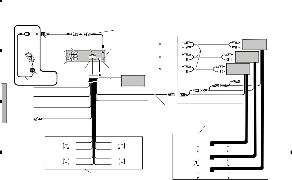
When not connecting a rear speaker lead to a subwoofer
5 |
|
|
DEH-P510UB/XN/UC |
USB port 2 |
|
|
Use a USB cable to connect the USB storage |
|
Pioneer CD-U150E USB cable |
20 cm device to the USB port 2. |
|
(7-7/8 in.) Pioneer CD-U150E USB cable is also available. |
|
|
(sold separately) |
For details, consult your dealer. |
Power amp |
50 cm (20 in.) |
|
(sold separately) |
Rear output |
This product |
Wired remote input |
To rear output |
|
iPod |
|
|
||
|
Hard-wired remote control |
Connect with RCA cables |
|
|
Front output |
|
(sold separately) |
Power amp |
|
Subwoofer output |
|
adaptor can be connected |
||
|
|
|||
|
(sold separately). |
|
(sold separately) |
|
|
|
To front output |
||
|
|
|
|
|
Antenna jack |
|
Power amp |
|
|
|
|
|
Fuse (10 A) |
IP-BUS input (Blue) |
(sold separately) |
|
|
|
To subwoofer |
6 |
Dock connector |
Multi-CD player |
output |
|
|
||
|
|
|
|
|
Interface cable |
IP-BUS cable (sold separately) |
|
DEH |
Yellow |
|
|
Connect to the constant 12 V supply terminal. |
|
|
|
- |
|
|
|
P510UB/XN/UC |
Red |
|
System remote control |
|
|
||
|
Connect to terminal controlled by |
|
|
|
Yellow/black |
|
|
|
ignition switch (12 V DC). |
|
|
|
If you use an equipment with Mute function, |
Blue/white |
|
|
|
||
|
Orange/white |
wire this lead to the Audio Mute lead on that |
|
|
Connect to system control terminal of the |
||
|
equipment. If not, keep the Audio Mute lead |
||
|
Connect to lighting switch terminal. |
amp or auto-antenna relay control terminal |
|
|
free of any connections. |
||
|
|
300 mA 12 V DC). |
|
|
|
|
|
|
Black (chassis ground) |
|
|
7 |
Connect to a clean, paint-free metal location. |
|
when |
|
|
|
P5100UB/XN/UC-DEH P510UB/XN/UC,-DEH |
DIAGRAM CONNECTION 4.2 |
|
|
5 |
|||
|
|
||
6 |
|||
|
|
|
|
|
|
|
|
7
8
|
|
|
White |
Gray |
||||
Front speaker |
|
|
|
|
|
|
|
Front speaker |
|
|
|
|
|
|
|
|
|
|
|
|
White/black |
Gray/black |
||||
Left |
|
|
|
|
Right |
|||
|
|
|
Green |
Violet |
||||
Rear speaker |
|
|
Green/black |
Violet/black |
|
|
|
Rear speaker |
|
|
|
|
|
|
|
||
|
|
|
|
|
|
|||
|
|
|
|
With a 2 speaker system, do not |
||||
|
|
|
|
connect anything to the speaker leads |
||||
|
|
|
|
that are not connected to speakers. |
||||
Subwoofer 
 Subwoofer
Front speaker
 Front speaker
Rear speaker
 Rear speaker
8
13
|
F |
|
E |
|
D |
|
C |
|
B |
|
A |
|
|
|
|
|
|
|
|

14
1
P510UB/XN/UC-DEH 3 2
4
F |
|
E |
|
D |
|
C |
|
B |
|
A |
|
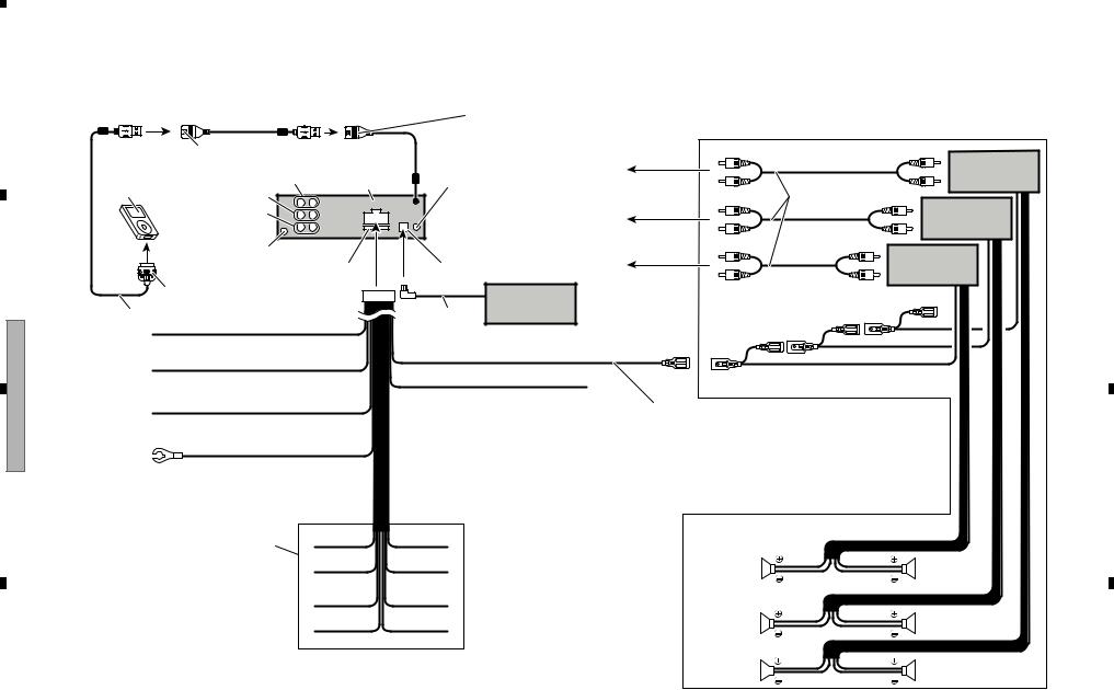
When using a subwoofer without using the optional amplifier |
|
|
|
DEH |
|
|||
Front output |
|
|
Hard-wired remote control |
|
|
|
P510UB/XN/UC,- |
1 |
DEH-P510UB/XN/UC |
|
|
USB port 2 |
|
|
|
|
|
|
|
20 cm |
Use a USB cable to connect the USB storage |
|
|
|
|
|
Pioneer CD-U150E USB cable |
(7-7/8 in.) Pioneer CD-U150E USB cable is also available. |
|
|
|
|
|
||
(sold separately) |
|
|
For details, consult your dealer. |
|
|
|
|
|
50 cm (20 in.) |
|
|
|
|
|
|
|
|
Rear output |
This product |
|
Wired remote input |
|
|
|
|
|
iPod |
|
|
|
|
|
|
|
|
|
|
|
|
|
|
|
|
|
Subwoofer output |
|
|
adaptor can be connected |
|
|
|
-DEH |
|
|
|
(sold separately). |
|
|
|
|
||
|
|
|
|
|
|
|
||
|
|
|
|
|
|
|
|
|
Antenna jack |
|
|
|
|
|
|
P5100UB/XN/UC |
|
|
Fuse (10 A) |
IP-BUS input (Blue) |
|
|
|
2 |
||
|
|
|
|
|
|
|||
Dock connector |
|
|
Multi-CD player |
|
Blue/white |
|
|
|
|
|
|
|
|
|
|
||
|
|
|
(old separately) |
|
|
|
|
|
Interface cable |
|
|
|
Connect to system control |
|
|
|
|
|
IP-BUS cable |
|
|
|
|
|||
|
|
|
|
|
terminal of the power amp or |
|
|
|
|
|
|
|
|
auto-antenna relay control |
|
|
|
|
|
|
|
|
terminal (max. 300 mA 12 V DC). |
|
|
|
Yellow/black |
|
|
|
White |
Gray |
|
|
|
|
|
|
|
|
|
|
|
|
If you use an equipment with Mute function, wire this lead to the Audio |
|
Front speaker |
|
|
Front speaker |
|
|
|
Mute lead on that equipment. If not, keep the Audio Mute lead free of |
|
|
|
|
|
|||
|
|
|
|
|
|
|
||
any connections. |
|
|
Left |
White/black |
Gray/black |
Right |
|
|
|
|
|
|
|
|
|
||
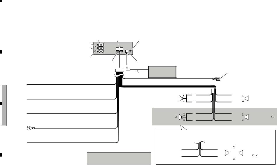
Yellow
Connect to the constant 12 V supply terminal.
Red
Connect to terminal controlled by ignition switch (12 V DC).
Orange/white
Connect to lighting switch terminal.
|
|
|
Green |
Violet |
|||
Subwoofer (4 ) |
|
|
Green/black |
Violet/black |
|
|
Subwoofer (4 ) |
|
|
|
|
||||
|
|
|
|
|
|
||
|
|
|
|
|
|
||
|
|
|
|
|
|
|
|
When using a subwoofer of 70 W (2  ), be sure to connect with Violet and Violet/black leads of this unit.
Do not connect anything with Green and Green/black leads.
3
Black (chassis ground) |
|
|
|
|
|
|
|
|
|
|
Green |
Violet |
|||||||
Connect to a clean, paint-free metal location. |
|
||||||||
|
|
|
Not used. |
|
|
|
|
|
Subwoofer |
|
|
|
|
|
|
|
|
||
|
Note |
|
|||||||
|
|
|
|
|
|
|
|||
|
|
|
|
|
|
|
(4 ) 2 |
||
|
Change the initial setting of this unit. |
|
Green/black |
Violet/black |
|||||
|
The subwoofer output of this unit is monaural. |
|
|
|
|
|
|
|
|
|
|
|
|
|
|
|
|
|
|
4
5
P510UB/XN/UC-DEH 7 6
8
When connecting speakers without using the internal amplifier
•If using this system, we recommend that this unit’s internal amp is turned off. For more details, refer to operation manual.
|
SB cable is also available. |
|
|
ur dealer. |
|
|
USB port 2 |
|
|
Use a USB cable to connect the USB storage |
|
Pioneer CD-U150E USB cable |
20 cm device to the USB port 2. |
|
(7-7/8 in.) Pioneer CD-U150E USB cable is also available. |
|
|
(sold separately) |
For details, consult your dealer. |
Power amp |
50 cm (20 in.) |
|
(sold separately) |
Rear output |
This product |
Wired remote input |
To rear output |
|
iPod |
|
|
||
|
Hard-wired remote control |
Connect with RCA cables |
|
|
Front output |
|
(sold separately) |
Power amp |
|
Subwoofer output |
|
adaptor can be connected |
||
|
|
|||
|
(sold separately). |
|
(sold separately) |
|
|
|
To front output |
||
|
|
|
|
Antenna jack |
|
|
Power amp |
|
|
|
|
Fuse (10 A) |
IP-BUS input (Blue) |
To subwoofer |
(sold separately) |
|
|
|
|
Dock connector |
Multi-CD player |
output |
|
|
|
||
|
|
|
|
Interface cable |
(sold separately) |
|
|
IP-BUS cable |
|
|
|
Yellow |
|
|
|
Connect to the constant 12 V supply terminal. |
|
|
|
Red |
|
System remote control |
|
Connect to terminal controlled by |
|
|
|
Yellow/black |
|
|
|
ignition switch (12 V DC). |
|
|
|
If you use an equipment with Mute function, |
Blue/white |
|
|
|
|
||
Orange/white |
wire this lead to the Audio Mute lead on that |
|
|
Connect to system control terminal of the |
|
||
equipment. If not, keep the Audio Mute lead |
|
||
Connect to lighting switch terminal. |
amp or auto-antenna relay control terminal |
|
|
free of any connections. |
|
||
|
300 mA 12 V DC). |
|
|
|
|
|
|
Black (chassis ground) |
|
|
|
Connect to a clean, paint-free metal location. |
|
|
|
White |
Gray |
|
|
Not used. |
|
|
|
White/black |
Gray/black |
Subwoofer |
Subwoofer |
|
|
||
Green |
Violet |
|
|
|
|
Front speaker |
Front speaker |
Green/black |
Violet/black |
|
|
|
|
Rear speaker |
Rear speaker |
P510UB/XN/UC-DEH |
|
|
5 |
||
|
|
|
|
|
|
6
7
8
15
|
F |
|
E |
|
D |
|
C |
|
B |
|
A |
|
|
|
|
|
|
|
|

16
1
P510UB/XN/UC-DEH 3 2
4
F |
|
E |
|
D |
|
C |
|
B |
|
A |
|
|
|
|
|
|
DEH |
|
|
|
|
|
33. Power amp |
P5150UB/XN/ES,- |
1 |
|
|
|
|
|
|
|
3. Rear output |
2. This product |
29. To rear output |
(sold separately) |
|
|
|
|
|
|
||||
4. Front output |
|
1.Wired remote input |
|
|
|
|
|
Hard-wired remote control |
|
33. Power amp |
|
|
|
5. Subwoofer output |
|
adaptor can be connected |
|
|
|
|
|
(sold separately). |
|
(sold separately) |
|
|
|
|
|
30. To front output |
|
|
||
|
|
|
|
|
|
|
6. Antenna jack |
|
|
|
33. Power amp |
|
|
|
|
7. IP-BUS input (Blue) |
|
-DEH |
|
|
10. Fuse (10 A) |
|
(sold separately) |
|
|||
|
31. To subwoofer output |
|
||||
|
|
|
|
|
||
|
|
9. Multi-CD player |
32. Connect |
|
|
|
|
|
(sold |
|
|
||
|
|
(sold separately) |
|
|
P5150UB/XN/ES1, |
2 |
|
|
8. IP-BUS cable |
|
|
||
|
|
|
|
|
|
|
11. Yellow |
|
|
|
|
|
|
Connect to the constant 12 V supply terminal. |
|
|
|
|
|
|
12. Red |
|
|
35. System remote |
|
|
|
Connect to terminal controlled by |
|
|
|
|
|
|
|
|
|
|
|
|
|
ignition switch (12 V DC). |
|
|
34. Blue/white |
|
|
|
13. Orange/white |
|
28. Yellow/black |
|
|
|
|
|
Connect to system control terminal |
|
|
|
||
Connect to lighting switch terminal. |
If you use an equipment with Mute |
power amp or auto-antenna relay |
|
|
|
|
|
|
function, wire this lead to the Audio Mute |
terminal (max. 300 mA 12 V DC) |
|
|
|
14. Black (chassis ground) |
|
lead on that equipment. If not, keep the |
|
|
-DEH |
|
|
Audio Mute lead free of any connections. |
|
|
|
||
Connect to a clean, paint-free metal location. |
|
|
|
P5190UB/XN/ID |
|
|
|
15. White |
17. Gray |
|
|
3 |
|
|
|
|
|
|
||
19. Front speaker |
|
19. Front speaker |
37. Subwoofer |
37. Subwoofer |
|
|
16. |
White/black |
18. Gray/black |
|
|
||
|
|
|
|
|||
|
22. Green |
24. Violet |
|
|
|
|
26. Rear speaker |
|
26. Rear speaker |
19. Front speaker |
19. Front speaker |
|
|
20. Left |
|
21. Right |
|
|
||
23. Green/black |
25. Violet/black |
|
|
|
|
|
27. With a 2 speaker system, do not connect |
26. Rear speaker |
|
26. Rear speaker |
anything to the speaker leads that are |
|
||
|
|
|
|
not connected to speakers. |
|
|
|
4
5
P510UB/XN/UC-DEH 7 6
8
3. Rear output |
2. This product |
4. Front output |
1.Wired remote input |
|
Hard-wired remote control |
||
|
||
5. Subwoofer output |
adaptor can be connected |
|
|
(sold separately). |
|
6. Antenna jack |
|
|
|
7. IP-BUS input (Blue) |
|
|
10. Fuse (10 A) |
|
|
9. Multi-CD player |
|
|
(sold separately) |
|
|
8. IP-BUS cable |
11.Yellow
Connect to the constant 12 V supply terminal.
19. Front speaker
12. Red
Connect to terminal controlled by 20. Left ignition switch (12 V DC).
13. Orange/white |
39. Subwoofer (4 ) |
|
Connect to lighting switch terminal. |
||
|
34. Blue/white
|
|
|
Connect to system control |
||||
|
|
|
terminal of the power amp or |
||||
|
|
|
|||||
|
|
|
auto-antenna relay control |
||||
|
|
|
terminal (max. 300 mA 12 V DC). |
||||
15. White |
|
17. Gray |
|
|
19. Front speaker |
||
|
|
|
|||||
|
|
|
|||||
|
|
|
|
|
|
|
|
|
|
|
|
|
|
|
|
16. White/black |
18. Gray/black |
|
|
21. Right |
|||
|
|
|
|
|
|
|
|
22. Green |
24. Violet |
|
|
|
|||
|
|
|
|
|
|
|
39. Subwoofer (4 ) |
23. Green/black |
25. Violet/black |
|
|
|
|
||
|
|
|
|
||||
14.Black (chassis ground)
Connect to a clean, paint-free metal location.
28.Yellow/black
If you use an equipment with Mute function, wire this lead to the Audio Mute lead on that equipment. If not, keep the Audio Mute lead free of any connections.
38.Note
Change the initial setting of this unit.
The subwoofer output of this unit is monaural.
40.When using a subwoofer of 70 W (2 ), be sure to connect with Violet and Violet/black leads of this unit.
Do not connect anything with Green and Green/black leads.
22. Green |
24. Violet |
|||||
41. Not used. |
|
|
|
|
|
42. Subwoofer |
|
|
|
|
|
||
23. Green/black |
25. Violet/black |
|
|
|
(4 ) 2 |
|
|
|
|
|
|
||
|
|
|
|
|
|
|
P5150UB/XN/ES,-DEH |
|
|
5 |
||
|
|
|
|
|
|
P5150UB/XN/ES1,-DEH |
6 |
|
|
|
|
|
|
|
P5190UB/XN/ID-DEH |
7 |
|
|
|
|
|
|
|
8
17
|
F |
|
E |
|
D |
|
C |
|
B |
|
A |
|
|
|
|
|
|
|
|

|
1 |
|
2 |
|
3 |
|
4 |
|
3. BASIC ITEMS FOR SERVICE
3.1 CHECK POINTS AFTER SERVICING
A
To keep the product quality after servicing, please confirm following check points.
|
|
No. |
|
Procedures |
|
Item to be confirmed |
|
|
1 |
|
Confirm whether the customer complain has |
|
The customer complain must not be |
|
|
|
|
been solved. |
|
reappeared. |
|
|
|
|
If the customer complain occurs with the |
|
Display, audio and operations must be |
|
|
|
|
|||
|
|
|
|
specific media, use it for the operation check. |
|
normal. |
|
|
2 |
CD |
Play back a CD. |
|
No malfunction on display, audio and |
|
|
|
|
(Track search) |
|
operation. |
|
|
3 |
FM/AM tuner |
Check FM/AM tuner action. |
|
Display, audio and operations must be |
B |
|
|
(Seek, Preset) |
|
normal. |
|
|
|
|
|
Switch band to check both FM and AM. |
|
|
|
|
4 |
|
Check whether no disc is inside the product. |
|
The media used for the operating check must |
|
|
|
|
|
|
be ejected. |
|
|
5 |
|
Appearance check |
|
No scratches or dirt on its appearance after |
|
|
|
|
|
|
receiving it for service. |
|
|
|
See the table below for the items to be checked regarding audio: |
|
||
|
|
|
|
|||
|
|
|
|
|
|
|
|
|
|
|
Item to be checked regarding audio |
|
|
|
|
|
|
|
|
|
|
|
|
|
Distortion |
|
|
C |
|
Noise |
|
|
||
|
Volume too low |
|
|
|||
|
|
|
|
|
|
|
|
|
|
|
Volume too high |
|
|
|
|
|
|
Volume fluctuating |
|
|
|
|
|
|
Sound interrupted |
|
|
|
|
|
|
|
|
|
|
|
|
|
|
|
|
|
|
|
|
|
|
|
D
E
F
18 |
DEH-P510UB/XN/UC |
|
1 |
|
2 |
|
3 |
|
4 |
|
|
|
|
|
|

|
5 |
|
6 |
|
7 |
|
8 |
3.2 PCB LOCATIONS
A Tuner Amp Assy
B Keyboard Unit
CCD Core Unit (S10.5iPod-Code3)
A:DEH-P510UB/XN/UC |
|
|
B:DEH-P5100UB/XN/UC |
|
|
C:DEH-P5150UB/XN/ES |
|
|
D:DEH-P5150UB/XN/ES1 |
|
|
E:DEH-P5190UB/XN/ID |
|
|
Unit Number |
: |
QWM3065(A) |
Unit Number |
: |
QWM3064(B) |
Unit Number |
: |
QWM3066(C,D,E) |
Unit Name |
: |
Tuner Amp Assy |
Unit Number |
: |
(A) |
Unit Number |
: |
(B,C,D,E) |
Unit Name |
: |
Keyboard Unit |
Unit Number |
: |
CWX3678 |
Unit Name |
: |
CD Core Unit(S10.5iPod-Code3) |
A
B
C
D
E
F
|
|
|
|
DEH-P510UB/XN/UC |
|
|
|
19 |
|
||
|
5 |
|
6 |
|
|
7 |
|
8 |
|
|
|
|
|
|
|
|
|
||||||

|
1 |
|
2 |
|
3 |
|
4 |
|
3.3 JIGS LIST
A |
- Jigs List |
|
Remarks
TCD-782 Checking the grating
Checking the grating (Two pieces)
- Grease List
B |
|
|
|
|
Remarks |
|
||
|
|
|
|
|
|
|
|
|
|
|
|
|
|
|
CD Mechanism Module |
||
|
|
|
|
GEM1045 |
CD Mechanism Module |
|||
|
|
|
|
|
|
|
|
|
|
|
|
|
|
|
|
|
|
3.4 CLEANING
CBefore shipping out the product, be sure to clean the following portions by using the prescribed cleaning tools:
|
|
Portions to be cleaned |
Cleaning tools |
|
|
CD pickup lenses |
Cleaning liquid : GEM1004 |
|
|
|
Cleaning paper : GED-008 |
|
|
|
|
|
|
|
D
E
F
20 |
DEH-P510UB/XN/UC |
|
1 |
|
2 |
|
3 |
|
4 |
|
|
|
|
|
|
|
5 |
|
6 |
|
7 |
|
8 |
|
A
B
C
D
E
F
|
|
|
|
DEH-P510UB/XN/UC |
|
|
|
21 |
|
||
|
5 |
|
6 |
|
|
7 |
|
8 |
|
|
|
|
|
|
|
|
|
||||||
1  2
2  3
3  4
4
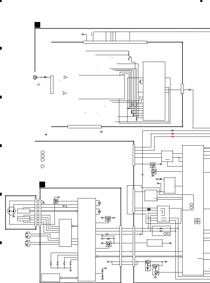
4. BLOCK DIAGRAM
A |
A TUNER AMP ASSY |
|
B
C
D
E
F
VDD |
CE2 |
SL |
DO |
CK |
CE1 |
|
|
|
|
|
|
|
|
|
|
|
|
|
|
|
|
|
|
|
|
|
|
|
|
|
|
|
|
|
|
|
|
13 |
7 |
6 |
|
|
|
|
|
|
|
|
|
5 |
|
10 |
9 |
8 |
|
|
|||||||
|
|
|
|
|
|
|
|
|
|
|
|
|
FM/AM TUNER UNIT |
|
|
|
ROM_VDD |
|
|
|
NC |
|
CE2 |
|
|
|
|
|
|
SL |
|
DI |
CK |
|
CE1 |
||||||||||||||||||||||
|
|
|
|
|
|
|
|
|
|
|
|
|
|
|
|
|
|
|
|
|
|
|
|
|
|
|
|
|
|
|
|
|
|
|
|
|
|
|
|
|
|
||||||||||||||||
|
|
|
|
|
|
|
|
|
|
|
|
|
|
|
|
|
|
|
|
|
|
|
|
|
|
|
|
|
|
|
|
|
|
|
|
|
|
|
|
|
|
|
|
|
|
|
|
|
|
|
|
|
|
|
|
||
|
|
|
|
|
|
|
|
|
|
|
|
|
|
|
|
|
|
|
|
|
|
|
|
|
|
|
|
|
|
|
|
|
|
|
|
|
|
|
|
|
|
|
|
|
|
|
|
|
|
|
|
|
|
|
|
|
|
|
|
|
|
|
|
|
|
|
|
|
|
|
|
|
|
|
|
|
|
|
|
|
|
|
|
|
|
|
|
|
|
|
|
|
|
|
|
|
|
|
|
|
|
|
|
|
|
|
|
|
|
|
|
|
|
|
|
|
|
|
|
|
|
|
|
|
|
|
|
|
|
|
|
|
|
|
|
|
|
|
|
|
|
|
|
|
|
|
|
|
|
|
|
|
IC3 EEPROM |
|
|
|
|
|
IC5 |
|
|
|
|
||||||||||
|
|
|
|
|
|
|
|
|
|
|
|
|
|
|
|
|
|
|
|
|
|
|
|
|
|
|
|
|
|
|
|
|
|
|
|
|
|
|
|
5.0V |
|
|
|
|
|
|
|
|
5V→ 3.3V |
|
|
||||||
|
|
|
|
|
|
|
|
|
|
|
|
|
|
|
|
|
|
|
|
|
|
|
|
|
|
|
|
|
|
|
|
|
|
|
|
|
|
|
|
|
|
|
|
|
|
|
|
|
|
|
|
|
|
|
|
|
|
ANTENNA CN401 |
|
|
|
|
|
|
|
AM |
ANT |
|
FMRF |
|
|
|
|
|
|
|
|
|
|
|
|
|
|
|
|
OSC |
|
|
|
|
LPF |
|
|
|
|
|
|
|
|
|
|
|
|||||||||||||
|
|
|
|
|
|
|
|
|
|
|
|
|
|
|
|
|
|
|
|
|
|
|
|
|
|
|
|
|
|
|
|
|
|
|
|
|
|
|
|
|
|
|
|
|
|||||||||||||
1 |
|
|
|
|
|
|
|
|
1 |
|
|
|
ATT |
|
|
|
|
|
|
|
|
|
|
|
|
|
|
|
|
|
|
|
|
|
|
|
|
|
|
|
|
IC1 |
|
|
|
|
|
|
|
|
|
||||||
|
2,3 |
|
|
|
|
|
|
|
|
|
|
|
|
|
|
|
|
|
|
|
|
|
|
|
|
|
|
|
|
|
|
|
|
|
|
|
|
|
|
|
|
|
|
|
|
|
|
|
|
|
|
||||||
|
|
|
|
|
|
|
|
|
|
|
|
|
|
|
|
|
|
|
|
|
|
|
|
|
|
|
|
|
|
|
|
|
|
|
|
|
|
|
|
|
|
|
|
|
|
|
|
|
|
|
|||||||
|
|
|
|
|
|
|
|
|
|
|
|
|
FM |
ANT |
|
|
|
|
|
|
|
|
|
|
|
|
|
|
|
|
|
|
|
|
|
|
|
|
|
|
|
|
3.3V |
|
|
|
|
|
|
|
|
|
|||||
|
|
|
|
|
|
|
|
|
|
|
|
|
|
|
|
|
|
|
|
|
|
|
|
|
|
|
|
|
|
|
|
|
|
|
|
|
|
|
|
|
|
|
|
|
|
|
|
|
|
|
|
|
|
|
|||
|
|
|
|
|
|
|
|
|
|
|
3 |
|
|
|
ATT |
|
|
|
|
|
|
|
|
|
|
|
|
|
|
|
|
|
|
|
|
|
|
|
|
|
|
|
MIXER, IF AMP |
|
|
|
|
|
|
|
|||||||
|
|
|
|
|
|
|
|
|
|
|
|
FMRF |
|
|
|
|
|
|
|
|
|
|
|
|
|
|
|
|
|
|
|
|
|
|
|
|
|
|
|||||||||||||||||||
|
|
|
|
|
|
|
|
|
|
|
|
|
|
|
|
|
|
|
|
|
|
|
|
|
|
|
|
|
|
|
|
|
|
|
|
|
|
|
|
|
|
|
|
|
|
|
|
|
|
|
|||||||
|
|
|
|
|
|
|
|
|
|
|
|
|
|
|
|
|
|
|
|
RF adj |
|
|
|
|
|
|
|
|
|
|
|
|
|
|
|
|
|
|
|
|
|
|
|
|
|
|
|
|
|
|
|
|
|
|
|
||
|
|
|
|
|
|
|
|
|
|
|
|
|
|
|
ANT adj |
|
|
|
|
|
|
|
|
|
|
|
|
|
|
|
|
|
|
|
|
|
|
|
|
|
|
|
|
|
|
|
|
|
|
||||||||
|
|
|
|
|
|
|
|
|
|
|
|
|
|
|
|
|
|
|
|
|
|
|
|
|
|
|
|
|
|
|
|
|
|
|
|
|
|
|
|
|
|
|
|
|
|
|
|
|
|
|
|
|
|
|
|
|
|
|
|
|
|
|
|
|
|
|
|
|
|
|
|
|
|
|
|
|
|
|
|
|
|
|
|
|
|
|
|
|
|
|
|
|
|
|
|
|
|
|
|
|
|
|
|
|
|
|
|
|
|
|
|
|
|
|
|
|
|
|
|
|
|
|
|
|
|
|
|
|
|
|
|
|
|
|
|
|
|
|
|
|
|
|
|
|
|
|
|
|
|
|
|
|
|
|
|
|
|
|
|
|
|
|
|
|
|
|
|
|
|
|
|
|
|
|
|
|
|
|
|
|
|
|
|
|
|
|
|
|
|
|
|
|
|
|
|
|
|
|
|
|
|
|
|
|
|
|
|
|
|
|
|
|
|
|
|
|
|
|
|
|
|
|
|
|
|
|
|
|
|
|
|
|
|
|
|
|
|
|
|
|
|
|
|
|
|
|
|
|
|
|
|
|
|
|
|
|
|
|
|
|
|
|
|
|
|
|
|
|
|
|
|
|
|
|
|
|
|
|
|
|
|
|
|
|
|
|
|
|
|
|
|
|
|
|
|
|
|
|
|
|
|
|
|
|
|
|
|
|
|
|
|
|
|
|
|
|
|
|
|
|
|
|
|
|
|
|
|
|
|
|
|
|
|
|
|
|
|
|
|
|
|
|
|
|
|
|
|
|
|
|
|
|
|
|
|
|
|
|
|
|
|
|
|
|
|
|
|
|
|
|
|
|
|
|
|
|
|
|
|
|
|
|
|
|
|
|
T51 |
|
CF52 |
|
|
|
|
|
|
|
|
|
|
|
|
||||
|
|
|
|
|
|
|
|
|
|
|
|
|
|
|
|
|
|
|
|
|
|
|
|
|
|
|
|
|
|
|
|
|
|
|
|
|
|
|
|
|
|
|
|
|
|
|
|
|
|
|
|
|
|
|
|
|
|
|
|
|
|
|
|
|
|
|
|
|
|
|
|
|
|
|
|
|
|
|
|
|
|
|
|
|
|
|
|
|
|
|
|
|
|
|
|
|
|
|
|
|
|
|
|
|
|
|
|
|
|
||||||
|
|
|
|
|
|
|
|
|
|
|
|
|
|
|
|
|
|
|
|
|
|
|
|
|
|
|
|
|
|
|
|
|
|
|
|
|
|
|
|
|
|
|
|
|
|
|
|
|
|
|
|
||||||
|
|
|
|
|
|
|
|
|
|
|
|
|
|
|
|
|
|
|
|
3.3VDD |
|
|
|
RFGND |
OSCGND |
DGND |
|
AUDIOGND |
|
|
NC |
|
|
VCC |
|
|
|
|
|
|
|
|
|
|
|
|
|
|
|
||||||||
|
|
|
|
|
|
|
|
|
|
|
|
|
|
|
|
|
|
|
|
|
|
|
|
|
|
|
|
|
|
|
|
|
|
|
|
IC4 |
|
|
|
|
|
||||||||||||||||
|
|
|
|
|
|
|
|
|
|
|
|
|
|
|
|
|
|
|
|
|
|
|
|
|
|
|
|
|
|
|
|
|
|
|
|
|
|
|
|
|
|
|
|
|
|
3.3V |
3.3V →2.5V |
|
2.5V |
||||||||
|
|
|
|
|
|
|
|
|
|
|
|
|
|
|
|
|
|
|
|
|
|
|
|
|
|
|
|
|
|
|
|
|
|
|
|
|
|
|
|
|
|
|
|
|
|
|
|
|
|
|
|
|
|
|
|
|
|
|
|
|
|
|
|
|
|
|
|
|
|
|
|
|
|
|
|
|
|
|
|
|
|
|
|
|
|
|
|
|
|
|
|
|
|
|
|
|
|
|
|
|
|
|
|
|
|
|
|
|
|
|
|
|
|
|
|
|
|
|
|
|
|
|
|
|
|
|
|
|
TUNER3V |
17 |
|
2 |
|
12 |
|
15 |
22 |
16 |
|
4 |
|
|
|
A8V |
|
|
|
|
|
|
|
||||||||||||||||||||||
|
|
|
|
|
|
|
|
|
|
|
|
|
|
|
|
|
|
|
|
|
|
|
|
|
|
|
|
|
|
|
|
|
|
|
|
|
|
|
|
|
|
|
|
|
|
|
|
|
|||||||||
|
|
|
|
|
|
1 |
|
|
|
IC451 |
|
|
3 |
|
|
|
|
|
|
|
|
|
|
|
|
|
|
|
|
|
|
|
|
|
|
|
|
|
|
|
|
|
|
|
|
|
|
|
|
|
|
||||||
|
|
|
|
|
|
A8V |
|
|
|
NJM2885DL1-33 |
|
|
|
|
|
|
|
|
|
|
|
|
|
|
|
|
|
|
|
|
|
|
|
|
|
|
|
|
|
|
|
|
|
|
|
|
|
|
|
||||||||
|
|
|
|
|
|
|
|
|
|
|
|
|
|
|
|
|
|
|
|
|
|
|
|
|
|
|
|
|
|
|
|
|
|
|
|
|
|
|
|
|
|
|
|
|
|
|
|
|
|
|
|||||||
|
|
|
|
|
|
|
|
|
|
|
|
|
|
|
|
|
|
|
|
|
|
|
|
|
|
|
|
|
|
|
|
|
|
|
|
|
|
|
|
|
|
|
|
|
|
|
|
|
|
|
|
|
|
|
|
|
|
|
|
|
|
|
|
|
|
|
|
|
|
|
|
|
|
|
|
|
|
|
|
|
|
|
|
|
|
|
|
|
|
|
|
|
|
|
|
|
|
|
|
|
|
|
|
|
|
|
|
|
|
|
|
|
|
|
|
A:DEH-P510UB/XN/UC
B:DEH-P5100UB/XN/UC
C:DEH-P5150UB/XN/ES :DEH-P5150UB/XN/ES1
D:DEH-P5190UB/XN/ID
|
|
|
|
|
C CD CORE UNIT(S10.5iPod-Code3) |
|
|
|
|
||||||||
PICKUP UNIT |
|
|
|
|
|
RF AMP, CD DECODER, MP3&WMA DECODER |
|
|
|||||||||
(P10.5)(SERVICE) |
|
|
|
|
|
|
|||||||||||
|
|
|
|
|
DIGITAL SERVO/DATA•PROCESSOR |
|
|
||||||||||
LD |
|
|
|
|
|
CN101 |
|
VDD2 |
|
CPU, USB HOST CONTROLLER |
|
|
|||||
|
|
|
|
|
|
|
|
|
|
|
|
1 |
|
|
|
||
|
|
|
LD- 15 |
15 |
|
Q101 |
|
|
|
141 |
LD |
USBXTAL |
|
|
|
||
|
|
|
|
|
|
|
|
|
|
|
|
|
X205 |
|
|
||
|
|
|
MD |
|
|
|
|
|
|
|
142 |
|
|
|
|
|
|
|
|
|
5 |
5 |
|
REFO |
|
|
PD |
/USBXTAL |
2 |
48MHz |
|
|
|||
|
|
|
VREF |
8 |
8 |
|
|
|
133 |
REFOUT |
|
|
|
||||
|
|
|
|
|
|
|
|
XTAL |
50 |
|
|
|
|||||
|
HOLOGRAM |
|
|
|
|
|
AC,BD,E,F |
|
|
|
|
|
|
||||
|
|
|
|
|
|
|
|
|
|
|
|
|
|
||||
|
|
|
|
|
|
|
|
|
|
|
|
|
X201 |
|
|
||
|
UNIT |
|
|
|
|
|
|
|
|
|
|
|
|
|
|
|
|
|
|
|
|
|
|
|
|
|
|
|
|
/XTAL 52 |
16.93MHz |
|
|
||
|
|
|
FOM |
|
|
FOM |
|
|
|
|
|
|
|
|
|||
|
|
|
3 |
3 |
|
CD |
|
|
|
|
Q102 |
|
|
||||
|
|
|
FOP |
FOP |
|
|
|
|
|
|
|
|
|
||||
MD |
FOCUS ACT. |
2 |
2 |
|
DRIVER |
|
|
|
|
VCC |
|
VDD2 |
|
||||
TRACKING ACT. |
TOP |
1 |
1 |
TOP |
|
IC301 |
|
|
|
|
|
|
|
|
|||
|
|
|
TOM |
4 |
4 |
TOM |
|
|
|
|
/PUEN |
39 |
|
|
|
||
|
|
|
LD+ |
|
|
|
|
BA5839FP |
|
|
|
|
|
CN701 |
|
||
|
|
|
14 |
14 |
|
12 |
TD,FD |
IC201 |
|
|
|
||||||
|
|
|
|
|
|
|
FOM |
|
|
|
|
|
|
|
|||
|
|
|
|
|
|
|
11 |
FOP |
|
SD,MD |
PE5661A DP |
5 |
|
DP 16 |
|||
|
|
|
|
|
|
|
14 |
TOP |
|
|
|
|
DM |
4 |
|
DM |
17 |
|
|
|
|
|
|
|
13 |
TOM |
|
|
|
|
|
|
|
||
|
SPINDLE |
M |
|
|
|
|
|
|
|
|
|
|
LOUT |
55 |
|
LOUT 13 |
|
|
MOTOR |
|
|
|
|
|
16 |
|
|
|
|
|
|
VDD |
|
|
|
|
|
|
|
|
|
|
SOP |
LOEJ |
22 |
28 |
LOEJ |
|
VDD2 |
|
|
|
|
|
|
|
|
|
|
|
15 |
SOM |
|
21 |
20 |
|
|
|
Q201 |
|
|
LOADING/CARRIAGE |
M |
|
|
|
|
18 |
LCOP CLCONT |
CLCONT |
|
VDD3 |
VDD |
9 |
|||||
|
MOTOR |
|
|
|
|
17 |
LCOM |
CONT |
9 |
41 |
|
|
|
|
|||
|
|
|
|
|
CONT |
|
|
|
|
||||||||
|
|
|
|
|
|
|
|
|
|
|
|
|
/ADENA |
17 |
|
|
|
|
|
|
|
|
|
|
|
|
|
|
8 |
12EJ |
/RESET |
16 |
|
/RESET |
8 |
|
|
|
|
|
|
|
|
|
|
|
|
|
|
|
|
||
|
|
|
|
|
|
|
|
|
|
|
7 |
8EJ |
|
|
BRST,BRXEN,BSRQ |
|
|
|
|
|
|
|
|
|
|
|
|
|
10 |
DSCSNS |
|
|
BDATA,BSCK |
|
|
|
|
|
|
|
|
|
|
|
|
|
9 |
|
|
|
|
|
|
|
|
|
|
|
|
|
|
|
|
|
HOME |
|
|
|
VD |
|
|
|
|
|
|
|
|
S904 |
S905 |
|
|
S901 |
|
|
|
VD |
2 |
||
|
|
|
|
|
|
|
|
|
|
|
|
|
|
||||
|
|
|
|
|
|
12EJ |
8EJ |
|
|
HOME |
|
|
|
|
|
1 |
|
|
|
|
|
|
|
|
|
S903 |
|
|
|
|
|
|
VD |
|
|
|
|
|
|
|
|
|
|
|
|
|
|
|
|
|
|
|
|
|
|
|
|
|
|
iPod CP |
DSCSNS |
|
|
|
|
|
|
|
|
||
|
|
|
|
|
|
|
|
|
|
|
VDSENS |
11 |
|
|
|
||
|
|
|
|
|
|
|
|
|
|
|
|
|
|
|
|
|
|
IC205
341S2162
DI
11 |
14 |
18 |
19 |
20 |
21 |
|
NC |
|
DO |
NC |
NC |
NC |
NC |
|
|
|
|
|
|
|
|
|
|
|
|
|
|
|
|
|
|
|
|
|
IC2
2.5V
Lch 23
DET, FM MPX,
TUNL
CDL
BUSL+
BUSL-
|
CN101 |
|
|
|
|
|
|
|
|
|
|
|
|
7 |
L+ |
|
|
IP-BUS DRIVER |
|
|
|
|
|||||
|
|
|
|
|
IC101 |
|
|
|
|
|
|
||
|
L- |
|
|
|
|
|
|
|
|
|
|
||
11 |
|
|
|
HA12241FP |
|
|
|
|
85 |
||||
|
|
|
|
|
|
|
|
|
|
|
MUTE |
||
IP BUS 5 |
BUS- |
|
|
5 |
BUS- |
DIN1 |
1 |
28 |
|
|
|||
|
|
TX |
SYSPW |
1 |
|||||||||
|
BUS+ |
|
|
6 |
|
|
|
|
2 |
27 |
|
|
|
1 |
|
|
BUS+ |
ROUT |
RX |
|
3 |
||||||
|
|
|
AMPM |
||||||||||
|
|
|
|
|
|
|
|
|
|
|
|
|
|
|
|
|
Q101 |
|
|
STBY |
|
|
19 |
RX2 |
|
|
|
8 |
ASENB |
|
|
|
BUP |
8 |
|
|
|
|
|
|
|
|
|
|
|
|
|
|
79 |
|
|
|
|||
|
|
|
|
|
|
|
|
|
|
IPPW |
|
|
|
|
|
Q102 |
|
|
|
|
|
|
80 |
ASENBO |
OELPW 20 |
||
|
|
|
|
|
USB 5V |
|
|||||||
|
|
|
|
|
|
|
IC501 |
|
|
|
|
|
|
|
|
|
|
|
1 |
BD9781HFP |
|
|
|
|
|||
|
|
|
BUP |
|
VIN |
|
|
|
|
|
|
||
|
|
|
USB5V |
|
|
|
|
|
EN 7 |
22 |
|
|
|
|
CN591 |
|
|
|
|
|
|
|
SYNC |
|
|
||
|
USB IF2 |
|
|
|
|
|
|
|
|
|
|
||
|
|
|
|
|
|
|
|
|
|
|
|
||
1 |
VBUS |
5 VOUT |
VIN |
1 |
2 |
SW |
|
|
|
|
|
|
|
|
|
IC571 |
|
|
|
|
|
|
|
|
|
|
|
|
|
BD6538G |
3 |
|
|
|
|
|
40 |
|
|
|
|
|
|
|
EN |
|
|
|
|
|
USBCTL2 |
|
|
||
USB |
|
|
OC |
4 |
|
|
|
|
|
51 |
FLG2 |
|
BUP |
|
|
|
SW USB |
|
|
|
|
|
|
||||
|
|
|
|
|
|
|
|
|
|
||||
|
|
|
|
IC761 |
|
|
|
|
A |
|
|
||
|
|
|
TC7MB3257FK |
|
|
|
|
|
|||||
2 D- |
|
9 |
3A |
|
|
S 1 |
|
52 |
USSEL B |
ILMPW |
41 |
||
3 D+ |
|
12 |
|
|
|
|
|
|
|
|
|
||
|
4A |
|
|
|
|
|
|
|
|
|
|||
|
|
|
13 |
4B2 |
|
|
|
|
|
|
SYSTEM |
|
|
|
|
|
10 |
|
|
|
|
|
|
|
|
||
|
|
|
3B2 |
|
|
|
|
|
|
CONTROLLER |
|
||
|
|
|
|
|
|
|
|
|
|
|
|||
|
|
|
2 |
1B1 |
|
|
1A |
4 |
|
|
IC 601(2/2) |
|
|
|
|
|
5 |
|
|
7 |
|
|
PEG509A8: A |
B |
|
||
|
|
|
2B1 |
|
|
2A |
|
|
|
||||
|
CN701 |
|
|
|
|
|
|
|
|
|
PEG576A8: C |
D |
|
|
|
|
|
|
|
|
|
|
|
|
|
|
|
4 |
DP |
|
|
|
|
|
|
|
|
|
|
|
35 |
3 |
DM |
|
|
|
|
|
|
|
|
|
|
ROT1 |
|
|
|
|
|
|
|
|
|
|
|
36 |
|||
|
LOUT |
|
|
|
|
C |
D |
|
|
|
|
ROT0 |
|
7 |
|
|
|
|
|
|
|
|
|
||||
|
|
MECHA 3.3V |
|
|
|
|
|
|
KYDT(RWRX) |
30 |
|||
|
|
|
|
|
|
|
|
29 |
|||||
|
|
|
|
|
|
|
|
|
|
|
DPDT(RWTX) |
||
|
VDD |
3 |
IC731 |
|
1 |
|
|
|
|
|
|
||
11 |
|
|
|
VDD |
|
|
|
|
|||||
|
|
NJM2885DL1-33 |
|
|
|
|
|
|
|
||||
|
|
|
|
|
|
|
|
|
|
|
|
|
V |
12 |
RESET |
|
|
|
|
|
|
|
|
92 |
CDRST |
|
38 |
|
|
|
|
|
|
|
|
|
|
|
|
SWVDD |
|
|
|
|
|
|
|
|
|
|
|
|
|
|
|
|
|
BRST,BRXEN,BSRQ,BDATA,BSCK |
|
|
|
|
|
||||||
|
|
Q751 |
MECHA VD |
|
|
|
|
|
|
|
DSENS |
91 |
|
|
VD |
|
|
|
|
|
|
|
|
||||
18 |
|
|
|
|
|
BUP |
|
|
|
|
|
||
|
|
Q752 |
|
|
|
|
|
|
|
|
|||
19 |
|
|
|
|
|
|
|
|
|
|
|
|
|
|
|
|
|
|
|
|
|
|
|
|
|
|
|
|
|
|
|
|
|
|
|
|
|
|
|
|
USB5V |
|
|
|
|
|
|
|
|
|
|
42 |
USBCTL1 |
45 |
|
|
|
|
|
|
|
|
|
|
|
|
|||
|
|
|
|
|
|
|
|
|
|
|
VDCONT |
FLG1 |
87 |
|
|
|
|
|
|
|
|
|
|
|
|
|
|
22 |
DEH-P510UB/XN/UC |
|
1 |
|
2 |
|
3 |
|
4 |
|
|
|
|
|
|

|
5 |
|
6 |
|
7 |
|
8 |
|
|
|
|
|
|
|
|
|
|
|
|
|
|
|
|
|
|
|
|
|
|
|
|
|
|
|
|
|
|
CN151 |
|
|
|
|
|
|
|
|
|
|
|
|
|
|
|
|
|
|
|
|
|
KEYD |
2 |
|
|
|
|
|
|
|
|
|
|
KEYD |
3 |
|
WIRED |
|
|
|
|
|
|
|
|
|
|
|
|
|
|
|
|
|
|
|
KEYAD |
89 |
|
|
|
|
|
|
|
|
|
|
KEYAD |
2 |
|
|
||
|
|
|
|
|
|
|
|
|
|
|
|
|
|
|
SYSTEM |
|
|
|
|
|
|
|
|
|
|
|
|
|
|
1 |
|
REMOTE |
|
|
|
|
|
|
|
|
|
|
|
|
|
|
|
|
|
CONTROLLER |
|
|
|
|
|
|
|
|
|
|
|
|
|
|
|
|
|
||
|
|
|
|
|
|
|
|
|
|
|
|
|
|
|
IC 601(1/2) |
|
|
|
|
|
|
|
|
|
|
|
|
CN302 |
|
|
|
|||
|
|
|
|
|
|
|
|
|
|
|
|
|
|
|
PEG509A8: A |
B |
|
FL |
|
|
|
|
|
|
|
|
|
|
|
|
|
|||
|
|
|
|
|
|
|
|
|
|
|
|
|
|
|
SP601 |
|
|
|
|
|
|
|
|
|
|
FL |
|
6 |
|
|
||||
|
|
|
|
|
|
|
|
|
|
|
|
|
|
|
PEG576A8: C |
|
|
|
|
|
|
|
|
|
|
|
|
|
|
|||||
|
|
|
|
|
|
|
|
|
|
|
|
|
|
|
D |
BUZZER |
|
|
|
|
|
|
|
|
|
|
|
|
|
|
|
|||
|
|
|
|
|
|
|
|
|
|
|
|
|
|
|
|
|
|
|
|
|
|
|
|
|
|
|
|
|
|
|
||||
|
|
|
|
|
|
CE2 |
|
|
|
|
|
|
69 |
|
|
PEE |
24 |
|
|
|
|
|
|
|
|
|
|
Q303 |
|
|
|
|
|
|
|
|
|
|
|
|
|
|
|
|
|
|
TUNPCE2 |
|
|
|
|
|
|
|
|
|
|
|
(1/2) |
|
|
|
|
|
|||||
|
|
|
|
|
|
CE1 |
|
|
|
|
|
|
70 |
TUNPCE1 |
|
|
|
|
|
|
|
|
|
|
|
|
|
|
|
|
|
|
|
|
|
|
|
|
|
|
DI |
|
|
|
|
|
|
|
46 |
|
|
|
RL |
|
|
|
|
|
|
|
|
|
|
RL |
|
2 |
RCA OUT |
|
|
|
|
|
|
|
|
DO |
|
|
|
|
|
|
47 |
TUNPDI |
|
|
|
|
|
|
|
|
|
|
|
|
|
|
|
|
|
|||
|
|
|
|
|
|
|
|
|
|
|
|
TUNPDO |
|
|
|
|
|
|
|
|
|
|
|
|
|
Q301 |
|
|
|
|
|
|||
|
|
|
|
|
|
CK |
|
|
|
|
|
|
48 |
TUNPCK |
|
XOUT |
11 |
|
|
|
|
|
|
|
|
|
|
|
|
|
|
|
||
|
|
|
|
|
|
SL |
|
|
|
|
|
|
95 |
SL |
|
|
|
|
|
|
|
|
|
|
|
|
|
|
|
|
|
|
|
|
|
|
|
|
|
|
|
|
|
|
|
|
|
|
|
|
|
|
|
|
|
|
|
|
|
|
|
|
|
|
|
|
|
||
|
|
|
|
|
|
|
|
|
|
|
|
|
|
|
|
|
XIN |
13 |
SWL |
|
|
|
|
|
|
|
|
|
|
SWL |
|
4 |
|
|
|
|
|
|
|
|
|
|
|
|
|
|
|
|
|
|
|
X601 |
|
|
|
|
|
|
|
|
|
|
|
|
|
|
|
||
|
|
|
|
|
|
|
|
|
|
|
|
|
|
|
|
|
|
|
|
|
|
|
|
|
|
|
|
|
|
|
|
|
||
|
|
|
|
|
|
|
|
|
|
|
|
|
|
|
|
|
|
15.000MHz |
|
|
|
|
Q304 |
|
|
|
|
|
|
|
|
|
|
|
|
|
|
|
|
|
|
|
|
|
|
|
|
|
|
|
|
|
|
|
|
|
|
|
|
|
|
|
|
|
|
|
|
|
|
|
|
|
|
|
|
|
|
|
|
|
|
|
|
|
|
|
|
|
|
BUP |
|
|
|
|
|
|
|
|
Q303 |
|
|
|
|
|
|
|
|
|
|
|
|
|
|
|
|
|
|
|
|
|
|
|
|
|
|
|
|
|
|
|
|
|
|
(2/2) |
|
|
|
|
|
|
|
|
|
|
|
|
RESET |
|
|
|
|
|
|
|
|
|
|
|
|
|
|
|
Q901 |
VDD |
|
|
|
|
|
|
|
|
||
|
|
|
|
|
|
|
|
|
|
|
|
|
|
|
|
|
|
|
|
|
|
|
|
|
|
|
|
|
|
|
||||
|
|
|
|
|
|
|
|
|
|
|
|
|
|
|
|
|
|
|
|
|
|
VDD |
|
|
|
|
|
|
|
|
|
|||
|
|
|
|
|
2 |
|
|
IC651 |
|
1 |
|
|
10 |
|
|
|
|
|
|
|
|
|
|
Q902 |
|
|
|
|
|
|
|
|
||
|
|
|
VDD |
|
|
|
|
|
RESET |
|
|
|
|
|
|
|
|
|
|
|
|
|
|
|
|
|
|
|||||||
|
|
|
|
|
|
S-80835CNNB-B8U |
|
|
|
|
|
|
|
|
|
|
|
|
|
|
|
|
|
|
|
|
|
|
|
|
||||
|
|
|
|
|
|
|
|
|
|
|
|
|
|
|
|
DALMON |
67 |
|
|
|
|
|
|
|
|
|
|
|
|
|
|
|
|
|
|
|
|
|
|
|
|
|
|
|
|
|
|
|
|
|
|
|
|
|
|
|
BSENS |
|
|
|
BUP |
|
CN981 |
|
|
||||
|
|
|
|
|
|
|
|
|
|
|
|
|
|
|
|
|
|
|
|
|
|
|
|
|
|
|
|
|
||||||
|
|
|
|
|
|
|
|
|
|
|
|
|
|
|
|
|
|
|
|
|
|
|
|
|
|
|
|
|
|
|
|
|||
|
|
|
|
|
|
|
|
|
|
|
|
|
|
|
|
|
BSENS |
73 |
|
|
|
|
|
|
|
|
|
|
|
B.UP |
16 |
|
|
|
|
|
|
|
|
ELECTRONIC VOLUME/ |
|
|
|
|
|
|
72 |
|
|
|
Q921 |
|
|
|
|
|
|
|
|
|
|
|
|
||||||
|
|
|
|
|
|
|
|
|
|
ASENS |
|
|
|
|
|
|
|
|
|
|
|
ACC |
14 |
|
|
|||||||||
|
|
|
|
|
SOURCE SELECTOR |
|
|
|
|
|
|
|
|
|
|
|
|
|
|
|
|
|
|
|
|
|
|
|||||||
|
|
|
|
|
|
|
|
|
|
|
|
|
|
|
|
|
|
|
|
ISENS |
|
|
|
|
|
|
||||||||
|
|
|
|
|
|
|
|
|
Noise_ |
20 |
|
|
93 |
|
|
|
|
|
|
|
ASENS |
|
|
|
|
|
|
|
|
|||||
|
|
|
|
|
|
|
|
|
|
|
ASLIN |
|
|
81 |
|
|
|
|
|
|
|
|
|
ILL |
|
|
|
|||||||
|
|
|
|
|
|
|
|
|
DET_out |
14 |
|
|
57 |
|
ISENS |
|
|
|
|
|
|
|
|
|
|
|
12 |
|
|
|||||
|
|
|
|
|
|
|
|
|
|
|
|
|
|
|
|
|
TEL IN |
|
|
|
|
|
|
|
|
|
|
|
||||||
|
|
|
|
|
|
|
|
|
MUTE |
|
|
EMUTE |
|
|
|
|
|
|
|
|
|
Q931 |
|
|
|
|
|
|
||||||
|
|
|
|
|
|
|
|
|
|
|
|
|
|
|
|
|
|
|
|
|
|
|
|
|
|
|
|
|||||||
|
|
|
|
|
|
|
|
|
|
|
|
SAOUT, SACLK |
|
|
|
TELIN |
8 |
|
|
|
Q961 |
|
|
|
|
|
|
|
TEL |
9 |
SOURCE |
|
||
|
|
|
|
|
|
|
|
IC201 |
|
|
|
|
|
|
|
|
|
|
|
|
|
|
|
|
|
|
|
|
|
|
|
|||
|
|
|
|
|
|
|
|
|
|
|
|
|
|
|
|
|
|
|
|
|
|
|
|
|
|
|
|
|
|
CONNECTOR |
|
|||
|
|
|
|
|
|
|
|
|
|
|
|
|
|
|
|
|
|
|
|
|
|
|
|
|
|
|
|
|
|
|
|
|||
|
|
|
|
|
|
|
PML017A |
|
40 |
|
|
|
|
|
|
|
|
|
|
|
|
|
|
|
21 |
|
|
FL+ |
|
|
|
|||
|
|
|
|
|
|
|
|
|
PRE/SW_L |
|
|
|
|
|
|
|
|
|
|
|
|
|
|
FL+ |
|
|
5 |
|
|
|||||
|
|
|
|
|
|
|
|
|
|
|
|
|
|
|
|
|
|
|
|
|
|
|
|
|
23 |
|
|
FL- |
|
|
|
|||
|
|
|
|
|
|
|
|
|
|
|
38 |
|
|
|
|
|
|
|
|
|
|
14 FLIN |
|
|
FL- |
|
|
7 |
|
|
||||
|
|
|
|
|
|
|
|
|
Front_L |
|
|
|
|
|
|
|
|
|
|
|
AMP |
5 |
|
|
RL+ |
|
|
|
||||||
|
|
|
|
|
8 |
|
|
|
|
|
39 |
|
|
|
|
|
|
|
|
|
|
12 |
|
|
IC351 |
RL+ |
3 |
|
|
RL- |
6 |
|
|
|
|
|
TUNL |
|
|
IN3_L |
|
|
Rear_L |
|
|
|
|
|
|
|
|
|
|
RLIN |
RL- |
|
|
|
|
|
|||||||||
|
|
|
|
|
|
|
|
|
EVOL VP+B |
|
|
|
|
|
|
|
PA2030A |
|
|
8 |
|
|
||||||||||||
|
|
CDL |
|
|
9 |
IN1_L |
|
|
|
|
|
|
Q241 |
|
|
|
|
BUP |
6,20 |
VCC |
|
|
B.REM |
25 |
|
|
BREM |
11 |
|
|
||||
|
|
BUSL+ |
|
|
7 |
|
|
|
|
|
43 |
|
|
|
|
|
|
|
|
|
|
|
|
|
|
|
|
|
||||||
|
|
|
|
IN4+_L |
|
|
VP |
|
|
|
Q242 |
|
OELB |
|
|
|
|
|
|
|
MUTE |
STBY |
|
|
|
GND 15 |
|
|
||||||
|
|
BUSL- |
|
|
6 IN4-_L |
|
|
|
|
|
|
|
|
|
|
|
|
|
|
|
|
22 |
4 |
|
|
|
|
|
|
|
|
|||
|
|
|
|
|
|
|
|
|
|
|
|
|
|
|
|
MUTE |
|
|
|
|
|
|
|
|
|
|
|
|
||||||
|
|
|
AUXL |
10 |
IN2_L |
|
|
|
|
|
|
|
|
|
|
|
|
|
|
|
A8V |
|
|
|
|
|
|
|
|
|
|
|
|
|
|
|
|
|
|
|
|
|
|
|
|
|
|
|
|
|
|
|
|
|
|
|
|
|
|
|
|
|
|
|
|
|
|
|
|
|
|
|
|
|
|
|
|
|
|
|
|
|
|
|
|
|
|
Q381 |
|
|
|
|
|
|
|
|
|
|
|
|
|
|
|
|
|
|
|
|
|
|
|
|
|
|
|
|
|
|
|
|
BUP |
|
|
B |
C |
D |
|
|
Q352 |
|
|
SYS+B |
|
|
|
|
|
|
|
|
|
|
|
|
|
|
|
|
|
|
|
|
|
|
|
|
|
|
|
|
|
|
|
|
|
IC911 |
|
|
|
|
|
|
||
|
|
85 |
|
|
|
|
|
|
|
|
|
|
|
|
|
|
|
|
|
|
|
|
|
|
|
|
|
|
|
|
|
|
|
|
|
MUTE |
|
|
|
|
|
|
|
|
|
|
|
|
|
|
|
|
|
|
|
|
|
|
|
|
NJM2388F84 |
|
|
|
|
|
|||
|
|
|
|
|
|
|
|
|
|
|
|
|
|
|
|
|
|
|
|
|
|
|
|
|
|
|
|
|
|
|
|
|
|
|
|
|
1 |
|
|
|
|
|
|
|
|
|
|
|
|
|
|
|
|
|
|
|
|
Q351 |
|
A8V |
2 VOUT |
VIN 1 |
BUP |
|
|
|
|||
|
SYSPW |
|
|
|
|
|
|
|
|
|
|
|
|
|
|
|
|
|
|
|
|
|
|
|
|
|
|
|||||||
|
|
3 |
|
|
|
|
|
|
|
|
|
|
|
|
|
|
|
|
|
|
|
|
|
|
|
|
|
CTRL |
|
|
|
|
|
|
|
AMPM |
|
|
|
|
|
|
|
|
|
|
|
|
|
|
|
|
|
|
|
A |
|
|
|
|
|
4 |
|
|
|
|
|
|
|
|
|
|
|
|
|
|
|
Q851 |
OEL+B |
|
|
|
|
|
|
|
|
|
|
|
|
|
|
|
|
|
|
|
|
|||||
|
|
|
|
|
|
|
|
|
|
|
|
|
|
|
|
|
|
|
|
|
|
|
|
|
|
|
|
|
|
|
||||
|
|
|
BUP |
|
Q852 |
|
|
|
|
|
|
|
|
|
OELB |
|
|
|
|
|
|
|
|
|
|
|
|
|
|
|
|
|
||
|
|
|
|
|
|
|
|
|
|
|
|
|
|
|
|
|
|
|
|
|
|
|
|
|
|
|
|
|
|
|
|
|
||
|
|
|
|
|
|
|
|
|
|
|
|
6,7 |
IC851 |
1 |
|
|
|
|
|
|
|
|
|
|
|
|
|
|
|
|
|
|
|
|
|
|
|
|
|
|
|
|
|
|
|
|
|
NJM2360AM |
|
|
|
|
|
|
|
|
|
|
|
|
|
|
|
|
|
|
|
||
|
OELPW |
20 |
|
|
|
|
|
|
|
|
|
|
|
|
|
|
|
|
|
|
|
|
|
|
|
|
|
|
|
|
|
|
|
|
|
|
|
|
|
AUX |
|
|
|
|
|
|
|
|
|
|
|
|
|
|
|
|
|
|
|
B KEYBOARD UNIT |
|
|
|||||||
|
|
|
|
|
|
|
CN801 |
|
|
CN1801 |
|
|
|
|
|
|
|
|
|
|
|
|
|
|
|
|
CN1821 |
|
|
|
||||
|
|
|
|
|
IC181 |
|
|
|
|
|
|
|
|
|
|
|
|
|
|
|
|
|
|
|
|
|
|
|
||||||
|
|
|
|
NJM2794V |
|
14 |
AUXL |
|
|
|
AUXL |
|
|
|
|
|
|
|
|
|
|
|
|
|
|
|
|
AUXR |
3 |
|
FRONT |
|
||
|
|
|
|
1 |
|
IN1+ |
|
19 |
|
19 |
|
|
|
|
|
|
|
|
|
|
|
|
|
|
|
|
AUXL |
2 |
|
|
||||
|
|
|
|
OUT1 |
IN1- |
|
12 |
AUXG |
18 |
|
18 |
AUXG |
|
|
|
|
|
|
|
|
|
|
|
|
|
|
|
|
AUXG |
1 |
|
AUX |
|
|
|
|
|
|
|
|
|
|
|
|
ILLUMI |
|
|
|
|
|
|
|
|
KEY MATRIX |
|
|
|
|
|||||||||||
|
|
|
|
|
|
|
|
|
|
|
|
|
|
|
|
|
|
|
|
|
|
|
|
|
|
|
|
|
|
|
|
|||
|
|
|
|
|
ILM+B |
|
|
|
|
|
|
|
|
|
|
|
D1834 |
Q1833 |
|
|
|
|
11 |
|
S1831 |
|
S1834 |
S1837 |
|
|
|
|
||
2 |
|
|
|
|
Q821 |
|
|
|
|
|
|
|
|
|
|
|
|
|
XOUT |
|
|
|
|
|
|
|||||||||
|
|
|
|
|
|
ILM+B |
|
|
|
ILM+B |
|
|
|
|
|
98 |
|
|
|
|
|
EJECT |
CLK/DISP OFF |
LOC/RPT |
|
|
|
|
||||||
|
|
|
|
|
|
|
|
|
|
|
|
|
|
|
|
|
|
|
|
X1901 |
|
|
|
|
||||||||||
|
|
BUP |
|
|
Q822 |
|
|
|
16 |
|
16 |
|
|
|
|
|
DIM |
|
|
|
|
|
|
|
|
|||||||||
|
|
|
|
|
|
|
|
|
|
|
|
|
|
|
|
|
|
|
|
|
|
XIN |
13 |
16MHz |
S1832 |
|
S1835 |
S1838 |
|
|
|
|
||
|
|
|
|
|
|
|
|
|
|
|
|
|
|
|
|
|
|
D1831 |
|
|
|
|
|
|
|
|
|
|
||||||
A |
|
|
|
|
|
|
|
|
|
|
|
|
|
|
|
|
|
|
|
|
|
|
|
|
SOURCE/OFF |
BAND/ESC |
DISP |
|
|
|
|
|||
|
|
|
|
|
|
|
|
|
|
|
|
|
|
|
|
|
- |
|
|
|
|
|
|
|
|
|
|
|
||||||
|
|
|
|
|
|
|
|
|
|
|
|
|
|
|
|
|
D1833 |
|
|
|
|
|
|
KD0-3,KS0-2 |
|
|
|
|
|
|
|
|
|
|
B |
|
|
|
|
|
|
|
|
|
|
|
|
|
|
|
|
|
D1835 |
|
|
|
|
|
|
S1833 |
|
S1836 |
S1839 |
|
|
S1834 |
|
||
|
41 |
|
|
|
|
|
|
|
|
|
|
|
|
|
|
|
- |
|
|
|
|
|
|
|
|
|
|
|
||||||
ILMPW |
|
|
|
|
|
|
|
|
|
|
|
|
Q1831 |
|
|
D1840 |
|
|
|
|
|
|
|
LIST |
SRTrv/SAT |
IPod/RDM |
|
|
TA/NEWS |
|
||||
|
|
|
|
|
|
|
|
|
|
|
|
|
|
|
|
|
|
|
|
|
|
|
|
|
|
|
||||||||
|
|
|
|
|
|
|
|
|
|
|
|
|
|
|
|
|
|
|
|
|
|
|
|
|
|
|
|
|
|
|
|
|
|
|
SYSTEM |
|
|
|
|
|
|
|
|
|
|
|
|
|
|
|
|
|
|
|
|
MICRO |
|
|
|
|
|
S1840 |
|
|
|
|
S1838 |
|
|
|
|
|
|
|
|
|
|
|
|
|
|
|
|
|
|
|
|
|
COMPUTER |
|
|
|
MUTE/SW BASS |
|
|
|
|
BACK/SCRL |
|
|||||
NTROLLER |
|
|
|
|
|
|
|
|
|
|
|
|
|
|
|
|
|
|
|
|
|
|
|
|
|
|
||||||||
|
|
|
|
|
|
|
|
|
|
|
|
|
|
|
|
|
|
|
IC1901 |
|
|
|
|
|
|
|
|
|
|
|
|
|||
C 601(2/2) |
|
|
|
|
|
|
|
|
|
|
|
|
|
|
|
|
|
99 |
ILL |
|
|
|
|
|
|
|
|
|
|
|
|
|||
|
|
|
|
|
|
|
|
|
|
|
|
|
|
|
|
|
PEG511A8 |
|
|
|
|
|
|
|
|
|
|
|
||||||
09A8: A |
B |
|
|
|
|
|
|
|
|
|
|
|
|
|
|
|
|
|
|
|
|
|
|
|
|
|
|
|
|
|
||||
|
|
|
|
|
|
|
|
|
|
|
|
|
|
|
|
|
|
|
|
|
|
|
A[1-17,19] |
|
|
|
|
|
|
|
|
|
||
76A8: C |
D |
|
|
|
|
|
|
|
|
|
|
|
|
|
ROTARY COMMANDER |
|
|
|
|
|
|
|
|
|
|
|
|
|
|
|
|
|||
|
|
|
|
|
|
|
|
|
|
|
|
|
|
|
|
|
|
|
|
|
D[0-15] |
|
|
|
|
|
|
|
|
|
||||
|
|
|
|
|
|
|
|
|
|
|
|
|
|
|
|
|
S1811 |
|
|
|
|
|
|
|
|
|
ROM |
|
|
|
|
|
|
|
|
|
35 |
|
|
|
|
|
|
ROT1 |
|
|
|
ROT0 |
Phase_B |
10 |
|
|
|
|
|
|
|
42 |
|
14 |
OE |
IC1981 |
|
|
|
|
|
|
|
|
ROT1 |
|
|
|
|
|
|
11 |
|
13 |
|
|
88 |
|
|
|
RD |
|
PD8184A: A |
|
|
|
|
|
||||||||||
|
|
36 |
|
|
|
|
|
|
ROT0 |
|
|
|
ROT1 |
Phase_A |
1 |
|
|
|
JOYST |
|
CS2 |
46 |
|
43 |
A19 |
PD8185A: B |
C D |
|
|
|
|
|||
|
ROT0 |
|
|
|
|
|
|
13 |
|
11 |
|
|
|
|
|
|
CS1 |
47 |
|
2 |
A18 |
|
|
|
|
|||||||||
|
|
|
|
|
|
|
|
|
|
|
|
|
|
|
|
|
|
|
|
|
|
|
48 |
|
12 |
|
|
|
|
|
|
|
||
|
|
30 |
|
|
|
|
|
|
KYDT |
|
|
|
KYDT |
|
|
|
|
|
28 |
|
|
|
CS0 |
|
CE |
|
|
|
|
|
|
|
||
KYDT(RWRX) |
|
|
|
|
|
|
7 |
|
7 |
|
|
|
|
|
KYDT |
|
|
|
|
|
23 |
VCC |
|
|
|
|
|
|
|
|||||
DPDT(RWTX) |
29 |
|
|
SWVDD |
|
|
DPDT |
9 |
|
9 |
DPDT |
|
|
VDD3.3V |
|
27 |
DPDT |
|
|
|
|
|
33 |
BYTE |
|
|
|
|
|
|
|
|||
|
|
|
|
|
|
|
|
|
|
|
|
|
|
|
|
|
|
|
|
|
|
|
|
|
|
|
|
|
|
|
||||
|
|
|
|
|
Q841 |
|
|
SWVDD |
|
|
|
SWVDD |
|
1,3 |
IC1951 |
5 |
14 |
|
|
|
|
|
|
|
|
|
|
|
|
|
|
|
||
|
|
VDD |
|
|
|
|
|
3 |
|
3 |
|
VCC1 |
|
|
|
22 |
|
|
|
CN1961 |
|
|
|
|
|
|
||||||||
|
|
|
|
|
|
|
|
|
|
|
|
|
|
|
|
S-1200B33-M5 |
60 |
VCC2 |
|
|
O-DC |
|
|
5 |
DC |
|
|
|
|
|
|
|||
|
|
|
|
|
|
|
|
|
|
|
|
|
|
|
|
REMOTE |
|
96 |
|
O-CSB |
23 |
|
|
3 |
CSB |
|
|
|
|
|
|
|||
|
|
|
|
|
|
|
|
|
|
|
|
|
|
|
|
|
Vref |
|
|
|
|
|
|
|
|
|
||||||||
|
|
38 |
|
|
|
|
|
|
|
|
|
|
|
|
CONTROL SENSOR |
|
|
|
O-RST |
24 |
|
|
4 |
RSTB |
|
|
|
|
|
|
||||
|
SWVDD |
|
|
|
Q842 |
|
|
|
|
|
|
|
|
|
|
3 |
97 |
|
|
|
|
26 |
|
|
|
|
|
|
|
|
|
|
||
|
|
|
|
|
|
|
|
|
|
|
OPT IN |
IC1931 |
AVCC |
|
|
O-CIN |
|
|
8 |
OSCIN |
OEL |
|
|
|
|
|||||||||
|
|
|
|
|
|
|
|
|
|
|
|
|
|
GP1UXC14RK 1 |
4 |
REM |
|
|
O-SID |
33 |
|
|
7 |
D7(SDIN) |
|
|
|
|
||||||
|
DSENS |
91 |
|
|
|
|
|
|
DSENS |
20 |
|
20 |
DSENS |
|
|
|
|
|
|
|
|
O-SCLK |
35 |
|
|
6 |
D6(SCLK) |
UNIT |
|
|
|
|
||
|
|
|
|
|
|
|
|
|
|
|
|
|
|
|
|
|
|
|
|
|
|
|
|
|
|
|
11 |
VDD |
|
|
|
|
|
|
|
|
|
|
|
|
|
|
|
|
|
|
|
OEL+B |
|
|
|
|
|
|
|
|
|
|
|
|
|
2 |
|
|
|
|
|
|
|
|
|
|
|
|
|
|
OEL+B |
10 |
|
10 |
|
|
|
|
|
|
|
|
|
|
|
|
|
|
. |
VCC |
|
|
|
|
|
|
||
|
|
|
|
|
USB IF1 |
|
|
|
|
|
|
|
|
|
|
|
|
|
|
|
12 |
|
|
|
|
|
|
|||||||
|
|
|
1 |
|
|
|
|
|
|
|
|
|
|
|
|
|
|
|
|
|
|
|
|
|
|
|
|
|
|
|
|
|
||
|
|
USB5V |
VIN |
IC551 |
|
|
|
|
|
|
|
|
|
|
|
|
|
|
|
|
|
|
|
|
|
|
|
|
|
|
|
|
||
USBCTL1 |
45 |
3 |
EN |
|
|
|
|
|
|
|
|
|
|
|
|
|
|
|
|
|
|
|
|
|
|
|
CN1851 |
|
|
|
||||
T |
FLG1 |
87 |
4 |
OC |
BD6538G |
|
|
5 US5V |
|
|
|
US5V |
|
|
|
|
|
|
|
|
|
|
|
|
|
|
|
|
USB5V |
|
|
|
|
|
|
|
VOUT |
8 |
|
8 |
|
|
|
|
|
|
|
|
|
|
|
|
|
|
|
|
|
1 |
|
|
|||||||||
|
|
|
|
|
|
|
|
|
USDP |
12 |
|
12 |
USDP |
|
|
|
|
|
|
|
|
|
|
|
|
|
|
|
|
USDP |
|
3 |
USB |
|
|
|
|
|
|
|
|
|
|
USDM 14 |
|
14 |
USDM |
|
|
|
|
|
|
|
|
|
|
|
|
|
|
|
|
USDM |
|
2 |
|
|
|
|
|
|
|
|
|
|
|
|
|
|
|
|
|
|
|
|
|
DEH-P510UB/XN/UC |
|
7 |
|
|
|
|
|
|
|
|
23 |
|||||
|
|
|
|
|
|
5 |
|
|
|
|
|
|
|
|
|
|
6 |
|
|
|
|
|
|
|
|
|
|
|
|
|
|
8 |
||
|
|
|
|
|
|
|
|
|
|
|
|
|
|
|
|
|
|
|
|
|
|
|
|
|
|
|
|
|
|
|
||||
A
B
C
D
E
F
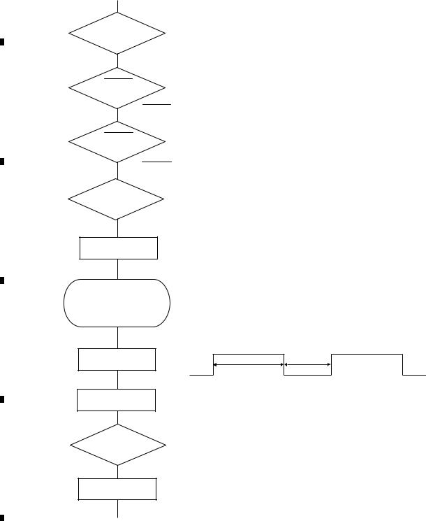
|
1 |
|
2 |
|
3 |
|
4 |
|
5. DIAGNOSIS
5.1 OPERATIONAL FLOWCHART
A
Power ON
Vcc = 5 V
Pin 14
BSENS
Pin 73
B
BSENS = L
ASENS
Pin 72
ASENS = L
DSENS
Pin 91
C |
2.0 V < DSENS < 4.5 V |
ASENBO <- H
Pin 80
Starts communication with Grille microcomputer.
D
SWVDD <- H
Pin 38
500 ms |
300 ms |
Source keys operative
In case of the above signal, the communication with Grille microcomputer may fail.
If the time interval is not 500 msec, the oscillator may be defective.
Source ON
E
SYSPW <- H
Pin 1
Completes power-on operation.
(After that, proceed to each source operation)
F
24 |
DEH-P510UB/XN/UC |
|
1 |
|
2 |
|
3 |
|
4 |
|
|
|
|
|
|
Loading...