


SERVICE STATION MANUAL
633779 ÷ 633786
X8 400 Euro 3

SERVICE STATION
MANUAL
X8 400 Euro 3
The descriptions and illustrations given in this publication are not binding. While the basic specifications as described and illustrated in this manual remain unchanged, PIAGGIO-GILERA reserves the right, at any time and without being required to update this publication beforehand, to make any changes to components, parts or accessories, which it considers necessary to improve the product or which are required for manufacturing or construction reasons.
Not all versions shown in this publication are available in all countries. The availability of single versions should be checked at the official Piaggio sales network.
"© Copyright 2005 - PIAGGIO & C. S.p.A. Pontedera. All rights reserved. Reproduction of this publication in whole or in part is prohibited."
PIAGGIO & C. S.p.A. - Q.C.S./After sales V.le Rinaldo Piaggio, 23 - 56025 PONTEDERA (Pi) www.piaggio.com

SERVICE STATION MANUAL
X8 400 Euro 3
This service station manual has been drawn up by Piaggio & C. Spa to be used by the workshops of Piaggio-Gilera dealers. It is assumed that the user of this manual for maintaining and repairing Piaggio vehicles has a basic knowledge of mechanical principles and vehicle repair technique procedures. Any significant changes to vehicle characteristics or to specific repair operations will be communicated by updates to this manual. Nevertheless, completely satisfactory work cannot be carried out without the necessary equipment and tools. It is therefore advisable to read the sections of this manual relating to appropriate tools, along with the appropriate tool catalogue.
N.B. Provides key information to make the procedure easier to understand and carry out.
CAUTION Refers to specific procedures to carry out for preventing damages to the vehicle.
WARNING Refers to specific procedures to carry out to prevent injuries to the repairer.
Personal safety Failure to completely observe these instructions will result in serious risk of personal injury.
Safeguarding the environment Sections marked with this symbol indicate the correct use of the vehicle to prevent damaging the environment.
Vehicle intactness The incomplete or non-observance of these regulations leads to the risk of serious damage to the vehicle and sometimes even the invalidity of the guarantee.


INDEX OF TOPICS
CHARACTERISTICS |
CHAR |
|
|
|
|
TOOLING |
TOOL |
|
|
|
|
MAINTENANCE |
MAIN |
|
|
|
|
ELECTRICAL SYSTEM |
ELE SYS |
|
|
|
|
ENGINE FROM VEHICLE |
ENG VE |
|
|
|
|
ENGINE |
ENG |
|
|
|
|
INJECTION |
INJEC |
|
|
|
|
SUSPENSIONS |
SUSP |
|
|
|
|
BRAKING SYSTEM |
BRAK SYS |
|
|
|
|
COOLING SYSTEM |
COOL SYS |
|
|
|
|
CHASSIS |
CHAS |
|
|
|
|
PRE-DELIVERY |
PRE DE |
|
|
|
|
TIME |
TIME |
|
|

INDEX OF TOPICS
CHARACTERISTICS |
CHAR |

X8 400 Euro 3 |
Characteristics |
|
|
This section describes the general specifications of the vehicle. |
|
Rules
This section describes general safety rules for any maintenance operations performed on the vehicle.
Safety rules
∙Should it be necessary to keep the engine running while servicing, make sure that the area or room is well ventilated, and use special exhaust fans, if required. never let the engine run in an enclosed area. Exhaust fumes are toxic.
∙The battery electrolyte contains sulphuric acid. Protect your eyes, clothes and skin. Sulphuric acid is highly corrosive; in the event of contact with your eyes or skin, rinse thoroughly with abundant water and seek immediate medical attention.
∙The battery produces hydrogen, a gas that can be highly explosive. Do not smoke and avoid sparks or flames near the battery, especially when charging it.
∙Fuel is highly flammable, and in some conditions it can be explosive. Do not smoke in the working area, and avoid open flames or sparks.
∙Clean the brake pads in a well ventilated environment, directing the compressed air jet so as to not inhale the dust produced by the wear of the friction material. Even though the latter contains no asbestos, dust inhalation is harmful.
Maintenance rules
∙Use original PIAGGIO spare parts and lubricants recommended by the Manufacturer. Nonoriginal or non-conforming spares may damage the vehicle.
∙Use only the special tools designed for this scooter.
∙Always use new gaskets, sealing rings and split pins upon reassembly.
∙After removal, clean the components using non-flammable or low fire-point solvent. Lubricate all the work surfaces except the tapered couplings before refitting.
∙After reassembly, check that all components have been installed properly and that they are in good working order.
∙For removal, overhaul and reassembly operations use only tools provided with metric measures. Metric bolts, nuts and screws are not interchangeable with coupling members with English measurement. Using unsuitable coupling members and tools may damage the scooter.
∙Should any interventions to the scooter electrical system be required, check that the electrical connections - especially earth and battery connections - have been implemented properly.
CHAR - 7

Characteristics |
X8 400 Euro 3 |
|
|
Vehicle identification
Chassis prefix
ZAPM52100÷1001
Engine prefix
M521M÷1001
Dimensions and mass
|
WEIGHT |
Specification |
Desc./Quantity |
Kerb weight |
206 kg |
Overall width |
750 mm |
Overall length |
2190 mm |
Wheelbase |
1540 mm |
Saddle height |
790 mm |
Overall height |
1360 mm |
CHAR - 8

X8 400 Euro 3 |
Characteristics |
|
|
Engine
|
|
ENGINE |
|
|
Specification |
Desc./Quantity |
|
|
Engine |
single-cylinder, four-stroke |
|
|
Bore x stroke |
85.8 X 69 mm |
|
|
Cubic capacity |
399 cm³ |
|
|
Compression ratio |
10.6 ± 0.5 : 1 |
|
|
Timing system |
Single overhead camshaft with integrated tone wheel, control |
|
|
|
from flywheel side chain, 4 valves and automatic start-up valve |
|
|
|
lifting device. |
|
|
Valve clearance: intake |
0.15 mm (when cold) |
|
|
Valve clearance: discharge |
0.15 mm (when cold) |
|
|
Valve clearance adjustment |
By threaded adjuster on the rockers |
|
|
Engine idle speed |
1500 ± 50 rpm |
|
|
Air filter |
sponge, impregnated with mixture (50% petrol and 50% oil) |
|
|
CO % value (measured at the intake manifold) |
1 - 1.5% |
|
|
Starting system |
Electric starter system with freewheel. |
|
|
Lubrication |
By trochoidal pump (inside the crankcase), pressure adjust- |
|
|
|
ment by-pass and oil filter. |
|
|
Lubrication pressure |
4 bar |
|
|
Minimum allowed (at 100° C) |
0.8 bar |
|
|
Fuel supply |
Electronic injection system with electric fuel pump, Ø 38 mm |
|
|
|
throttle body and single injector. |
|
|
Maximum power (to the crankshaft) |
24.5 kW at 7250 rpm |
|
|
Maximum torque (to the crankshaft) |
36 Nm at 5500 rpm |
|
|
Cooling system |
Fluid circulation through a motor-driven pump, 3-way thermo- |
|
|
|
stat and electric fan. |
|
|
|
|
|
Transmission |
|
|
|
|
TRANSMISSIONS |
|
|
|
Specification |
Desc./Quantity |
|
|
Transmission |
With automatic expandable pulley variator with torque server, |
|
|
|
V belt, automatic clutch, gear reduction unit and transmission |
|
|
|
housing with forced air circulation cooling. |
|
|
|
|
|
Capacities |
|
|
|
|
|
CAPACITY |
|
|
Specification |
Desc./Quantity |
|
|
Engine oil (empty) |
1.7 lt. |
|
|
Engine oil (at oil and filter change) |
1.5 lt. |
|
|
Fuel tank capacity |
Tank capacity: ~12 l (approximate value) |
|
|
Rear hub |
approx. 250 cc. |
|
|
Cooling system |
approx. 1.8 litres |
|
|
|
|
|
Electrical system |
|
|
|
|
ELECTRICAL SYSTEM |
|
|
|
Specification |
Desc./Quantity |
|
|
Electronic ignition |
inductive, high efficiency integrated with the injection system, |
|
|
|
with variable timing and separate HV coil. |
|
|
Spark plug |
NGK CR7EKB |
|
|
Spark plug |
CHAMPION RG6YC |
|
|
Battery |
Dry-cell lead-acid battery, 12V-14Ah |
|
|
Generator |
Three-phase alternating current |
|
CHAR - 9

Characteristics |
X8 400 Euro 3 |
|
|
Frame and suspensions
FRAME AND SUSPENSIONS
|
Specification |
Desc./Quantity |
|
|
Chassis |
Welded steel pipes with pressed sheet metal stiffening |
|
|
Front suspension |
Double effect hydraulic telescopic fork with Ø 35 mm stems and |
|
|
|
pin backwards with connections for double brake calliper |
|
|
Front fork max. stroke |
104 mm |
|
|
Rear suspension |
Engine with swinging fork attached to the frame by means of |
|
|
|
an arm with one degree of freedom and a pair of double effect |
|
|
|
hydraulic shock absorbers with 4 adjustable preload positions. |
|
|
|
|
|
Brakes |
|
|
|
|
|
BRAKES |
|
|
Specification |
Desc./Quantity |
|
|
Front brake |
Ø 240mm double disk brake with hydraulic control activated by |
|
|
|
the handlebar right-hand lever. |
|
|
Rear brake |
Ø 240 mm disc brake with hydraulic control activated by han- |
|
|
|
dlebar left lever. |
|
|
|
|
|
Wheels and tyres |
|
|
|
|
WHEELS AND TYRES |
Specification |
Desc./Quantity |
Tyre pressure (cold) front |
2.1 bar |
Tyre pressure (cold) rear |
2.3 bar (2.5 bar with passenger) |
Front wheel rim |
Die-cast aluminium alloy, 3.50"x14'' |
Rear wheel rim |
Die-cast aluminium alloy 4.50"x14" |
Front tyre |
Tubeless 120/70 - 14'' - Michelin Gold Standard M/C 55S |
Rear tyre |
Tubeless 140/70 - 14'' - Michelin Gold Standard M/C 68S |
|
|
N.B. |
|
CHECK AND ADJUST TYRE PRESSURE WITH TYRES AT AMBIENT TEMPERATURE. ADJUST PRESSURE ACCORDING TO THE WEIGHT OF RIDER AND ACCESSORIES.
CAUTION
IT IS MANDATORY TO ADOPT EXCLUSIVELY "S" CLASS TYRES, WHICH GUARANTEE CORRECT VEHICLE PERFORMANCE AT THE DIFFERENT SCOOTER SPEEDS. USING ANY OTHER TYRE MAY RESULT IN VEHICLE INSTABILITY. IT IS ADVISABLE TO USE TYRE TYPES RECOMMENDED BY PIAGGIO.
Tightening Torques
|
FRAME |
Name |
Torque in Nm |
Electric pump locking ring nut |
20 |
|
BRAKE SYSTEM |
Name |
Torque in Nm |
Brake calliper coupling |
20 - 24 |
Front brake disc mounting |
5 ÷ 6 • |
CHAR - 10
X8 400 Euro 3 |
Characteristics |
|
|
Name |
Torque in Nm |
Rear brake disc mounting |
11 ÷ 13 |
Front brake calliper mounting on fork |
20 ÷ 25 |
Rear calliper support on crankcase retainer |
20 ÷ 25 |
Pipe / brake calliper coupling |
20 ÷ 25 |
Pipe / brake pump coupling |
20 ÷ 25 |
Front brake pipe splitter coupling |
20 ÷ 25 |
• Lock with Loctite 243 medium strength threadlock |
|
FRONT SUSPENSION
Name |
Torque in Nm |
|
Front wheel axle |
45 |
÷ 50 |
Holding torque of lower ring nut |
20 |
÷ 25 |
Fork stem mounting to the plate |
20 |
÷ 25 |
Steering lower ring nut |
10 - 13 ** |
|
Upper steering ring nut |
36 - 39 |
|
Stem upper cap |
35 - 55 |
|
Fixing screw handlebar to steering tube |
45 |
÷ 50 |
Pumping element fixing screw |
25 - 35 |
|
Safety screw on fork leg |
6 |
÷ 7 |
Wheel fastening screws |
33 - 37 |
|
* tighten and loosen completely. ** tighten and loosen by 90°.
REAR SUSPENSION
Name |
Torque in Nm |
|
Upper shock absorber clamp |
33 |
÷ 41 |
Lower shock absorber clamp |
33 |
÷ 41 |
Shock absorber-crankcase attachment bracket |
20 |
÷ 25 |
Rear wheel axle |
104 |
÷ 126 |
Muffler arm clamping screws |
27 |
÷ 30 |
|
ENGINE ASSEMBLY |
Name |
Torque in Nm |
Starter motor screws |
11 ÷ 13 |
THERMAL GROUP AND TIMING SYSTEM
Name |
Torque in Nm |
|
Spark plug |
12 |
÷ 14 |
Head fixing stud bolts |
*** |
|
Head fixing nuts |
10 |
- 12 |
Exhaust / intake head fixing nuts |
10 |
- 12 |
Head lubrication control jet |
5 |
- 7 |
Coolant temperature sensor: |
10 |
- 12 |
Lambda probe on exhaust manifold |
10 |
- 12 |
injector fixing screw |
3 |
÷ 4 |
Counterweight screw |
7 ÷ 8.5 |
|
Tensioner sliding block fixing screw |
10 |
- 14 |
Rpm timing sensor fixing screw |
3 |
- 4 |
Valve lifter mass stop bell fixing screws |
30 |
- 35 |
Inlet manifold screws |
11 |
÷ 13 |
Tappet cover fixing screws |
7 |
- 9 |
Throttle body fixing screws |
11 |
÷ 13 |
Head fixing screws |
10 |
- 12 |
Camshaft retaining bracket screws: |
4 |
÷ 6 |
Tightener screw: |
5 |
- 6 |
Tightener fastening screws: |
11 |
÷ 13 |
*** Apply a preliminary torque of 7 Nm in a crossed sequence. - Tighten by 90° in a crossed sequence. - tighten again by 90° in a criss-crossed sequence.
CRANKCASE AND CRANKSHAFT
Name |
Torque in Nm |
Countershaft fixing nut |
25 ÷ 29 |
Engine oil filter |
12 - 16 |
CHAR - 11

Characteristics |
X8 400 Euro 3 |
|
|
Name |
Torque in Nm |
Engine oil drainage plug |
24 ÷ 30 |
Engine-crankcase coupling screws |
11 ÷ 13 |
Oil pump screws |
5 - 6 |
Gear mounting on crankshaft screws |
10 -12 |
Bulkhead screws for oil pump housing cover |
8 - 10 |
FINAL REDUCTION
Name |
Torque in Nm |
Rear hub cover screws |
24 ÷ 27 |
TRANSMISSION COVER
Name |
Torque in Nm |
|
Driven pulley nut |
92 - 100 |
|
driving pulley nut |
160 - 175 |
|
Anti-vibration roller screw |
16.7 |
÷ 19.6 |
M8 retainers for transmission cover |
23 |
÷ 26 |
M6 retainer |
11 |
÷ 13 |
Anti-vibration roller retainer |
17 - 19 |
|
Clutch ring nut |
65 - 75 |
|
Air conveyor screws |
11 |
÷ 12 |
Water pump cover screws |
3 |
÷ 4 |
External transmission cover screws |
7 |
÷ 9 |
Flywheel cover screws |
11 - 13 |
|
FLYWHEEL COVER
Name |
Torque in Nm |
|
Chain guide sliding block retain plate fastening screws |
3 |
÷ 4 |
Flywheel fixing nut |
115 - 125 |
|
Stator retainers |
8 - 10 |
|
Blow-by recovery duct fixing screws |
3 - 4 |
|
Screw fixing freewheel to flywheel |
13 |
÷ 15 |
Stator cable harness guide bracket screws |
3 - 4 |
|
Supporting screws with bulkhead |
0.3 - 0.4 |
|
Minimum oil pressure sensor |
12 |
÷ 14 |
Water pump impeller |
4 |
÷ 5 |
|
LUBRICATION |
Name |
Torque in Nm |
Oil pump cover screws |
0.7 ÷ 0.9 |
Screws fixing oil pump to crankcase |
5 - 6 |
See also |
|
Refitting
Refitting
Overhaul
Overhaul data
This section provides the main information for scooter servicing.
Assembly clearances
CHAR - 12
X8 400 Euro 3 |
Characteristics |
|
|
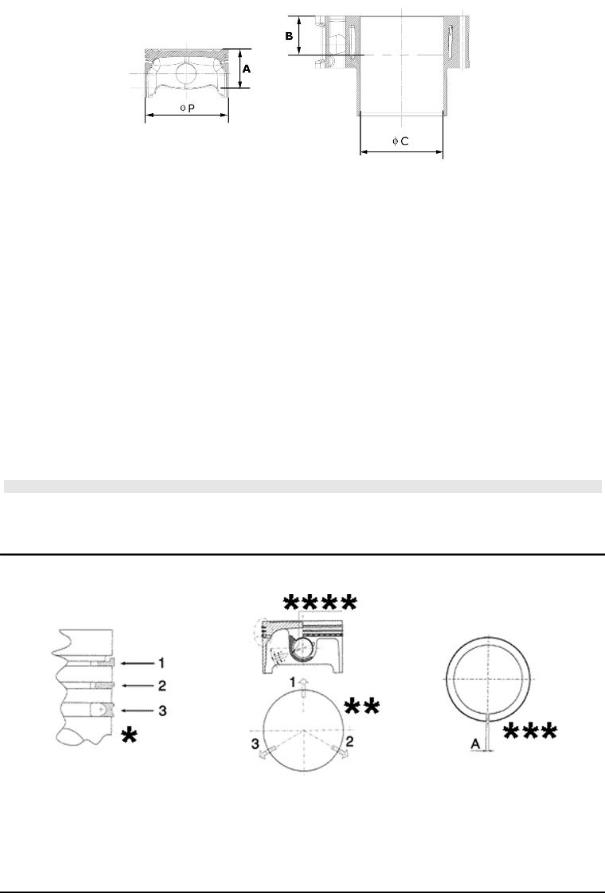
Cylinder - piston assy.
HEIGHT AT WHICH THE DIAMETER SHOULD BE MEASURED
Specification |
Desc./Quantity |
A |
43.2 mm |
B |
43 mm |
|
CYLINDERPISTON |
Specification |
Desc./Quantity |
Cylinder diameter C |
85.8 - +0.018 -0.01 mm |
Piston Ø P |
85.768 ± 0.014 mm |
CYLINDER - PISTON |
|
COUPLING CATEGORIES
Name |
Initials |
Cylinder |
Piston |
Play on fitting |
CylinderPiston |
A |
85.790÷85.797 |
85.754÷85.761 |
0.029÷0.043 |
CylinderPiston |
B |
85.797÷85.804 |
85.761 ÷ 85.768 |
0.029÷0.043 |
CylinderPiston |
C |
85.804÷85.811 |
85.768÷85.775 |
0.029÷0.043 |
CylinderPiston |
D |
85.811÷85.818 |
85.775÷85.782 |
0.029÷0.043 |
CATEGORIES OF COUPLING
N.B.
THE PISTON MUST BE INSTALLED WITH THE ARROW FACING TOWARDS THE EXHAUST SIDE, THE PISTON RINGS MUST BE INSTALLED WITH THE WORD «TOP» OR THE STAMPED MARK FACING UPWARDS.
Piston rings
*Fit rings «2» and «3» with the word «TOP» facing upwards.
**Position the openings in the rings as shown here.
***Value «A» of sealing ring inside the cylinder
****Ring opening
CHAR - 13
Characteristics |
X8 400 Euro 3 |
|
|
|
SEAL RINGS |
Specification |
Desc./Quantity |
1st compression ring |
0.150 ÷0.300 |
2nd compression ring |
0.250 ÷0.500 |
Oil scraper ring |
0.250 ÷0.500 |
SEAL RINGS
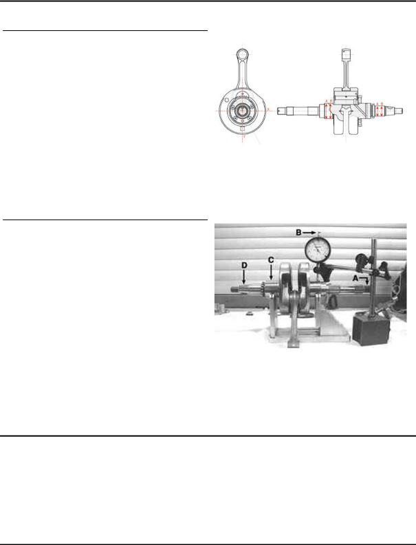
Crankcase - crankshaft - connecting rod
Diameter of crankshaft bearings.
Measure the bearings on both axes x-y.
|
CRANKSHAFT |
Specification |
Desc./Quantity |
Cat. 1 |
Standard diameter: 40.020÷40.026 |
Cat. 2 |
Standard diameter: 40.026÷40.032 |
Crankshaft alignment
Specific tooling
020335Y Magnetic support for dial gauge
MAX. ADMISSIBLE DISPLACEMENT
Specification |
Desc./Quantity |
A = |
0.15 mm |
B = |
0.010 mm |
C = |
0.010 mm |
D = |
0.10 mm |
Crankcase / countershaft coupling
Besides considering it should match the crankshaft, the crankcase is chosen according to the centre to centre distance between the seat of the crankshaft and that of the contra-rotating shaft.
Both the centre to centre distance and the pair of gears driving the contra-rotating shaft are divided into two types (A and B) to be matched (A with A and B with B).
CHAR - 14
X8 400 Euro 3 |
Characteristics |
|
|
This selection is useful to keep the difference between the working distance of the gears and their distance without clearance at a given value in order to avoid abnormal noise.
TYPE A
Specification |
Desc./Quantity |
Centre to centre distance of the gears without clearance |
76.937 ÷ 76.867 |
Centre to centre distance on the crankcase |
77.022 ÷ 76.992 |
TYPE B
Specification |
Desc./Quantity |
Centre to centre distance of the gears without clearance |
76.907 ÷ 76.837 |
Centre to centre distance on the crankcase |
76.992 ÷ 76.962 |
The gears with centre to centre distance without clearance between 76.867 and 76.907 are considered universal and can be fitted to either crankcase type.
Either the pair of gears or the crankcase is identified with the letter referring to the type (on the crankcase, this mark is found at the cylinder mouth, flywheel side).
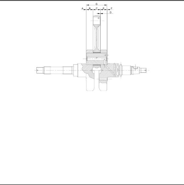
AXIAL CLEARANCE BETWEEN CRANKSHAFT AND CONNECTING ROD
|
Name |
Description |
Dimensions |
Initials |
Quantity |
|
|
Transmission-side |
|
1±0.025 |
A |
D = 0.20 - 0.50 |
|
|
shoulder |
|
|
|
|
|
|
Half-shaft, transmission |
|
20.9 -0.05 |
B |
D = 0.20 - 0.50 |
|
|
side |
|
|
|
|
|
|
Connecting rod |
|
22 -0.10 -0.15 |
C |
D = 0.20 - 0.50 |
|
|
Flywheel-side shoulder |
|
1.8±0.025 |
F |
D = 0.20 - 0.50 |
|
|
Flywheel-side half-shaft |
|
19.6 -0.05 |
E |
D = 0.20 - 0.50 |
|
|
Complete crankshaft |
|
65.5 +0.10 -0.05 |
G |
D = 0.20 - 0.50 |
|
|
|
|
|
|
|
|
CHAR - 15
Characteristics |
X8 400 Euro 3 |
|
|
Characteristic
crankshaft / crankcase axial clearance:
0.1 ÷ 0.405 mm
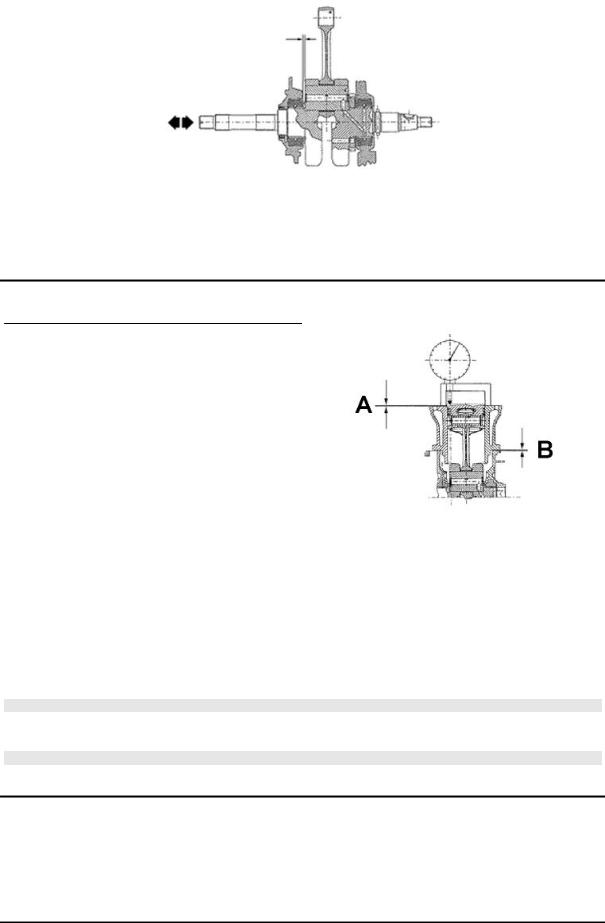
Slot packing system
Shimming system for keeping the compression ratio
DISTANCE «A» IS A PROTRUSION OR RECESS VALUE OF
THE PISTON CROWN WITH RESPECT TO THE CYLINDER
PLANE.
DISTANCE «A» HELPS DETERMINE THE THICKNESS OF
GASKET «B» THAT HAS TO BE FITTED TO THE CYLINDER
HEAD IN ORDER TO RESTORE COMPRESSION RATIO.
BASE GASKET «B» MUST BE THICKER THE MORE THE
PLANE FORMED BY THE PISTON TOP PROTRUDES
FROM THE PLANE FORMED BY THE CYLINDER HEAD. ON
THE OTHER HAND, THE MORE THE PISTON TOP IS RE-
CESSED INTO THE CYLINDER TOP PLANE, THE SMALL-
ER THE GASKET THICKNESS.
Characteristic
Compression ratio
10.6 ± 0.5 : 1
BASE GASKET THICKNESS
Name |
Measure A |
Thickness |
«A» MEASURE TAKEN |
- 0.185 - - 0.10 |
0.4 ± 0.05 |
«A» MEASURE TAKEN |
- 0.10 - + 0.10 |
0.6 ± 0.05 |
«A» MEASURE TAKEN |
+ 0.10 ÷ + 0.185 |
0.8 ± 0.05 |
N.B.
VALUES INDICATED WITH «-» REFER TO PISTON CROWN RECESSES WITH RESPECT TO THE CYLINDER PLANE.
N.B.
DISTANCE «A» MUST BE MEASURED WITHOUT ANY GASKET FITTED AT «B»
CHAR - 16

X8 400 Euro 3 |
Characteristics |
|
|
Products
PRODUCTS
|
Product |
Description |
Specifications |
|
|
AGIP ROTRA 80W-90 |
Rear hub oil |
SAE 80W/90 Oil that exceeds the re- |
|
|
|
|
quirements of API GL3 specifications |
|
|
AGIP FILTER OIL |
Oil for air filter sponge |
Mineral oil with specific additives for in- |
|
|
|
|
creased adhesiveness |
|
|
AGIP CITY HI TEC 4T |
Engine oil |
SAE 5W-40, API SL, ACEA A3, JASO MA |
|
|
|
|
Synthetic oil |
|
|
AGIP BRAKE 4 |
Brake fluid |
FMVSS DOT 4 Synthetic fluid |
|
|
SPECIAL AGIP PERMANENT fluid |
coolant |
Monoethylene glycol-based antifreeze |
|
|
|
|
fluid, CUNA NC 956-16 |
|
|
AUTOSOL METAL POLISH |
Muffler cleaning paste |
Specific product for cleaning and polish- |
|
|
|
|
ing stainless steel mufflers |
|
|
AGIP GP 330 |
Grease for brake levers, throttle |
White calcium complex soap-based |
|
|
|
|
spray grease with NLGI 2; ISO-L-XBCIB2 |
|
|
AGIP CITY TEC 2T |
Mixer oil |
synthetic oil for 2-stroke engines: JASO |
|
|
|
|
FC, ISO-L-EGD |
|
|
|
|
|
|
CHAR - 17

INDEX OF TOPICS
TOOLING |
TOOL |

X8 400 Euro 3 |
Tooling |
||
|
|
|
|
|
|
ATTREZZATURA SPECIFICA BUONA |
|
|
Stores code |
Description |
|
|
001330Y |
Tool for fitting steering seats |
|
|
|
|
|
|
001467Y002 |
Driver for OD 73 mm bearing |
|
001467Y006 |
Pliers to extract 20 mm bearings |
|
|
001467Y007 |
Driver for OD 54-mm bearings |
001467Y008 |
Pliers to extract 17 mm ø bearings |
|
|
001467Y014 |
Pliers to extract ø 15-mm bearings |
TOOL - 19

Tooling |
X8 400 Euro 3 |
|
|
Stores code |
Description |
001467Y031 |
Bell |
|
|
001467Y034 |
Pliers to extract ø 15-mm bearings |
001467Y035 |
Belle for OD 47-mm bearings |
|
|
002465Y |
Pliers for circlips |
006029Y |
Punch for fitting fifth wheel seat on steer- |
|
ing tube |
|
|
020004Y |
Punch for removing fifth wheels from |
|
headstock |
TOOL - 20
X8 400 Euro 3 |
Tooling |
|
|
Stores code |
Description |
020055Y |
Wrench for steering tube ring nut |
|
|
020150Y |
Air heater support |
|
|
020151Y |
Air heater |
|
|
020193Y |
Oil pressure gauge |
020201Y |
Spacer bushing driving tube |
020262Y |
Crankcase splitting strip |
020306Y |
Punch for assembling valve sealing rings |
|
|
TOOL - 21

Tooling |
X8 400 Euro 3 |
|
|
Stores code |
Description |
020329Y |
MityVac vacuum-operated pump |
020330Y |
Stroboscopic light to check timing |
|
|
020331Y |
Digital multimeter |
020333Y |
Single battery charger |
|
|
020334Y |
Multiple battery charger |
TOOL - 22
X8 400 Euro 3 |
Tooling |
|
|
Stores code |
Description |
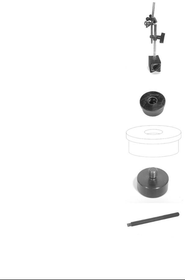
020335Y |
Magnetic support for dial gauge |
|
|
020357Y |
32x35-mm Adaptor |
020358Y |
37x40-mm Adaptor |
020359Y |
42x47-mm Adaptor |
020360Y |
52x55-mm Adaptor |
|
|
020364Y |
25-mm guide |
020376Y |
Adaptor handle |
|
|
020382Y012 |
bush (valve removing tool) |
TOOL - 23

Tooling |
X8 400 Euro 3 |
|
|
Stores code |
Description |
020412Y |
15 mm guide |
|
|
020424Y |
Driven pulley roller casing fitting punch |
020431Y |
Valve oil seal extractor |
|
|
020434Y |
Oil pressure control fitting |
|
020439Y |
17 mm guide |
|
|
|
|
|
|
|
|
|
TOOL - 24
X8 400 Euro 3 |
Tooling |
|
|
Stores code |
Description |
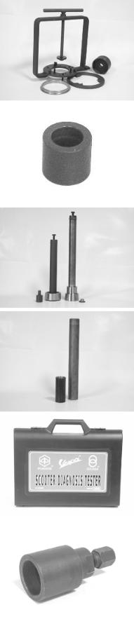
020444Y |
Tool for fitting/ removing the driven pulley |
|
clutch |
020456Y |
Ø 24 mm adaptor |
|
|
020458Y |
Puller for lower bearing on steering tube |
020459Y |
Punch for fitting bearing on steering tube |
|
|
020460Y |
Scooter diagnosis and tester |
|
020467Y |
Flywheel extractor |
|
|
|
|
|
|
|
|
|
TOOL - 25

Tooling |
X8 400 Euro 3 |
|
|
Stores code |
Description |
020468Y |
Piston fitting band |
020469Y |
Reprogramming kit for scooter diagnostic |
|
tester |
|
|
020470Y |
Pin retainers installation tool |
020471Y |
Pin for countershaft timing |
|
|
020472Y |
Flywheel lock wrench |
TOOL - 26
X8 400 Euro 3 |
Tooling |
|
|
Stores code |
Description |
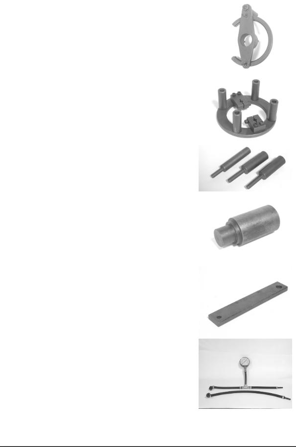
020474Y |
Driving pulley lock wrench |
|
|
020475Y |
Piston position checking tool |
020476Y |
Stud bolt set |
|
|
020478Y |
Punch for driven pulley roller casing |
020479Y |
Countershaft lock wrench |
|
|
020480Y |
Petrol pressure check set |
TOOL - 27

Tooling |
X8 400 Euro 3 |
|
|
Stores code |
Description |
020481Y |
Control unit interface wiring |
|
|
020482Y |
Engine support |
020483Y |
30 mm guide |
|
|
020512Y |
Piston fitting fork |
020527Y |
Engine support base |
|
|
|
020604Y011 |
Fitting adapter |
|
|
020565Y |
Flywheel lock calliper spanner |
|
|
|
|
|
|
|
|
|
TOOL - 28

X8 400 Euro 3 |
Tooling |
|
|
Stores code |
Description |
Marelli MIU diagnosis software |
Marelli MIU diagnosis software |
|
020640y |
software euro 3 |
|
|
|
|
|
|
|
|
|
TOOL - 29

INDEX OF TOPICS
MAINTENANCE |
MAIN |
 Loading...