


PIAGGIO WOULD LIKE TO THANK YOU
for choosing one of its products. We have prepared this manual to help you to get the very best from your scooter. Please read it carefully before riding the scooter for the first time. It contains information, tips and precautions for using your scooter. It also describes features, details and devices to assure you that you have made the right choice. We believe that if you follow our suggestions, you will soon get to know your new vehicle and it will serve you well for a long time to come. This booklet forms an integral part of the scooter; should the scooter be sold, it must be transferred to the new owner.
MP3 250 i.e.
The instructions given in this manual are intended to provide a clear, simple guide to using your scooter; this booklet also details routine maintenance procedures and regular checks that should be carried out on the vehicle at an authorised Dealer or Service Centre. The booklet also contains instructions for simple repairs. Any operations not specifically described in this manual require the use of special tools and/or particular technical knowledge: to carry out these operations refer to any authorised Dealer of Service Centres.
2

Personal safety
Failure to completely observe these instructions will result in serious risk of personal injury.
Safeguarding the environment
Sections marked with this symbol indicate the correct use of the vehicle to prevent damaging the environment.
Vehicle intactness
The incomplete or non-observance of these regulations leads to the risk of serious damage to the vehicle and sometimes even the invalidity of the guarantee.
The signs that you see on this page are very important. They are used to highlight those parts of the booklet that should be read with particular care. As you can see, each sign consists of a different graphic symbol, making it quick and easy to locate the various topics.
3
4
VEHICLE...................................................................................... |
7 |
Dashboard................................................................................ |
9 |
Analogue instrument panel....................................................... |
10 |
Clock......................................................................................... |
12 |
Digital lcd display...................................................................... |
13 |
Maintenance icons................................................................ |
13 |
*MODE* button...................................................................... |
14 |
Key switch................................................................................. |
14 |
Locking the steering wheel.................................................... |
14 |
Releasing the steering wheel................................................ |
14 |
Switch direction indicators........................................................ |
15 |
Horn button............................................................................... |
15 |
Light switch............................................................................... |
16 |
Emergency flashing light button................................................ |
16 |
Start-up button.......................................................................... |
17 |
Engine stop button.................................................................... |
17 |
Front suspension unlock-lock switch........................................ |
18 |
The immobilizer system............................................................ |
18 |
Keys...................................................................................... |
18 |
Immobilizerdevice enabled indicator led............................... |
20 |
Operation............................................................................... |
20 |
Programming the immobilizer system................................... |
21 |
Saddle opening remote control................................................. |
22 |
Remote control programming................................................ |
22 |
Accessing the fuel tank............................................................. |
24 |
The saddle................................................................................ |
25 |
Opening the saddle to access the helmet compartment by |
|
remote control....................................................................... |
26 |
Opening the saddle to access the helmet compartment in an |
|
emergency............................................................................. |
27 |
Opening of top box.................................................................... |
28 |
Identification.............................................................................. |
28 |
USE.............................................................................................. |
29 |
|
INDEX |
Checks...................................................................................... |
30 |
Refuelling.................................................................................. |
31 |
Tyre pressure............................................................................ |
33 |
Shock absorbers adjustment.................................................... |
34 |
Running in................................................................................. |
35 |
Starting up the engine............................................................... |
36 |
Precautions........................................................................... |
39 |
Difficult start up......................................................................... |
39 |
Stopping the engine.................................................................. |
40 |
Stand......................................................................................... |
40 |
Automatic transmission............................................................. |
41 |
Safe driving............................................................................... |
41 |
Front suspension locking system.............................................. |
44 |
MAINTENANCE........................................................................... |
49 |
Engine oil level.......................................................................... |
50 |
Engine oil level check............................................................ |
50 |
Engine oil top-up................................................................... |
50 |
Warning light (insufficient oil pressure)................................. |
50 |
Engine oil change.................................................................. |
51 |
Hub oil level.............................................................................. |
52 |
Tyres......................................................................................... |
54 |
Spark plug dismantlement........................................................ |
55 |
Removing the air filter............................................................... |
56 |
Air filter cleaning....................................................................... |
56 |
Cooling fluid level...................................................................... |
57 |
Checking the brake oil level...................................................... |
58 |
Braking system fluid top up................................................... |
58 |
Battery....................................................................................... |
60 |
Use of a new battery............................................................. |
60 |
Long periods of inactivity.......................................................... |
61 |
Fuses........................................................................................ |
61 |
Front light group........................................................................ |
66 |
Headlight adjustment............................................................. |
66 |
5
Front direction indicators........................................................... |
70 |
Rear optical unit........................................................................ |
70 |
Number plate light..................................................................... |
72 |
Helmet compartment lighting bulb............................................ |
72 |
Rear-view mirrors...................................................................... |
73 |
Front and rear disc brake.......................................................... |
73 |
Puncture.................................................................................... |
74 |
Periods of inactivity................................................................... |
75 |
Cleaning the vehicle.................................................................. |
75 |
TECHNICAL DATA...................................................................... |
81 |
Kit equipment............................................................................ |
85 |
SPARE PARTS AND ACCESSORIES........................................ |
87 |
Warnings................................................................................... |
88 |
PROGRAMMED MAINTENANCE............................................... |
91 |
Scheduled maintenance table................................................... |
92 |
6

MP3 250 i.e.
Chap. 01
Vehicle
7

01_01
01_02
1 Vehicle
8
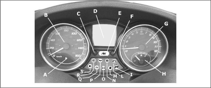
Dashboard (01_01, 01_02)
A = Ignition key-switch
B = Starter button
C = Throttle control
D = Front brake lever
E = Turn indicator switch
F = Headlight switch
G = Rear brake lever
H = Horn button
I = Engine cut-off switch
L = Mode switch
M = Emergency turn indicator switch
N = Analogue instrument panel
O = Indicator unit
P = Bag hook
Q = Digital instrument panel
R = Front suspension locking-unlocking switch (if available)
Vehicle 1
9
1 Vehicle
01_03
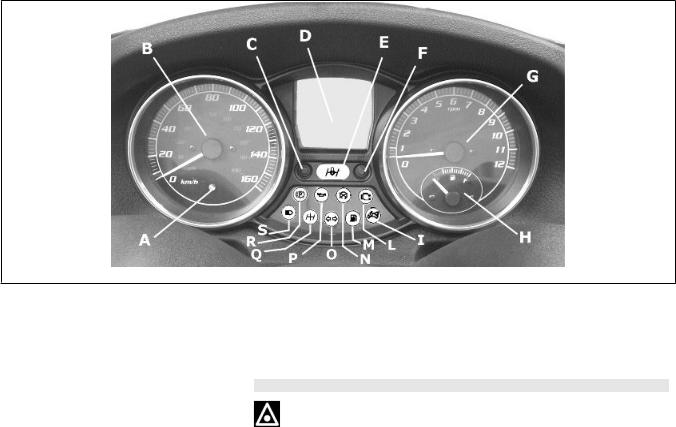
Analogue instrument panel (01_03)
A = Led immobilizer / anti-theft device
B= Speedometer with twin scale (km/h and mph)
C = CLOCK switch
D = Digital display
E = Front suspension locking system warning light (if available)
F = SET switch
G = Rpm indicator
10
H = Fuel gauge
I = Warning light for helmet compartment courtesy light on
L = Engine control telltale light and injection system failure warning light M = Low fuel warning light
N = Engine stop warning light
D= Turn indicator warning light
P = Low oil pressure warning light
Q = Front suspension locking system failure warning light (if available) R = Warning light for parking brake engaged
C = High-beam warning light
Vehicle 1
11

1 Vehicle
01_04
Clock (01_04)
Pushing the «CLOCK» button for less than 1 second displays the following sequence:
∙TIME
∙DATE
To set the clock push and hold the «CLOCK» button longer than 3 seconds.
The numbers showing the hours will begin flashing.
Set the hour using the «SET» button. Push the «CLOCK» button again and the minutes numbers start flashing.
Set the minutes using the «SET»button. Push the «CLOCK» button again and the day numbers start flashing.
12
01_05
01_06
Set the day with the «SET» button. Push the «CLOCK» button again and the month numbers start flashing.
Set the month with the «SET» button. Push the «CLOCK» button again and the year numbers start flashing.
Set the year with the «SET» button. Press the «CLOCK » button again for 4 seconds to exit the adjustment menu.
During the reset process, not pressing any buttons for a period longer than 8 seconds ends the process automatically and the display shows the modified time.
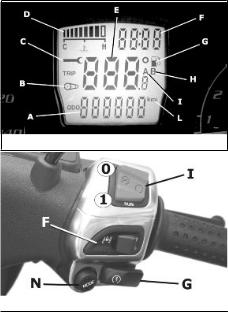
Digital lcd display (01_05)
A = Total odometer gauge
B = «BELT» maintenance icon
C = «SERVICE» maintenance icon
D = Engine coolant temperature indicator
E = Trip odometer gauge (A-B) and ambient temperature (selected with the MODE button)
F = TIME-DATE indicator
G = Low fuel warning light
H = Trip odometer gauge (B)
I = Trip odometer gauge (A)
L = Kilometre - mile indicator
Maintenance icons
The icons signal the user that scheduled maintenance operations should be carried out. A flashing «SERVICE» icon signals the need to carry out the scheduled maintenance service. A flashing «BELT» icon signals the driving belt needs replacing. In any case, vehicle maintenance must be carried out at the kilometre service intervals recommended in this booklet.
Vehicle 1
13
1 Vehicle
WARNING
REFER TO THE «SCHEDULED MAINTENANCE TABLE» FOR FURTHER MAIN-
TENANCE OPERATIONS
*MODE* button (01_06)
Pushing the «MODE» switch (N) for less than a second displays the following function sequence:
1.Trip odometer "A"
2.Trip odometer "B"
3.Ambient temperature "°"
Push the «MODE» switch (N) for longer than 3 seconds to zero set the trip odometer
|
Key switch (01_07, 01_08) |
||
|
|||
|
1. |
LOCK = Ignition disabled, extractable key, mechanical antitheft device ena- |
|
|
|
bled. The parking brake cannot be released when pressed and cannot be |
|
|
|
pressed when released. |
|
|
2. |
« OFF » = Ignition disabled, extractable key, mechanical antitheft device dis- |
|
|
|
abled and enabled/disabled parking brake. |
|
|
3. |
ON = Ready to start, non-extractable key, mechanical antitheft device disa- |
|
|
|
bled. |
|
|
4. |
«HELMET COMPARTMENT OPENING» = Helmet compartment opening |
|
01_07 |
|
position. Press the key when in "OFF" or "ON" and turn it anticlockwise. |
|
5. |
«FUEL TANK COVER OPENING» = Fuel tank cover opening position. Press |
||
|
|||
the key when in "OFF" or "ON" and turn it clockwise.
Locking the steering wheel
Turn the handlebar to the left as far as it will go, turn the key to position "LOCK" and remove the key.
Releasing the steering wheel
Reinsert the key and turn it to «OFF».
14

CAUTION
DO NOT TURN THE KEY TO «LOCK» OR «OFF» WHILE RIDING.
01_08
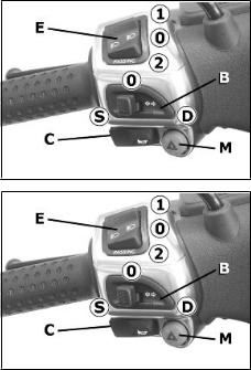
Switch direction indicators (01_09)
Lever towards "S" = Left turn indicator is switched on;
Lever towards "D" = Right turn indicator is switched on;
The lever «B» automatically returns to «0 » and the turn indicators remain on; press the lever to turn them off.
01_09
Horn button (01_10)
Push the «C» button to sound the horn.
01_10
Vehicle 1
15
01_11
01_12
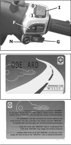
Light switch (01_11)
0 = Low-beam light
1 = High beam light
2 = Passing (flashing)
Emergency flashing light button (01_12)
It enables the activation of the 4 turn indicators simultaneously. The control «M» can be enabled only with the key set to «ON», but once enabled, it keeps functioning even if the key is set to «OFF» or «LOCK». To disable this function, simply turn the key switch to «ON».
1 Vehicle
16

Start-up button (01_13)
Turn the key to «ON».
Turn the RUN/OFF switch to «RUN».
Pull one of the two brake levers.
Press the «G» switch to start the engine.
Warning, in vehicles fitted with a suspension locking system, the vehicle will start but will remain at idling speed if the rider is not seated on the saddle in riding position.
01_13
Engine stop button (01_14)
Functioning of the engine cut-off switch "I":
0 = OFF
1 = RUN
01_14
Vehicle 1
17
1 Vehicle
01_15
01_16
01_17
Front suspension unlock-lock switch (01_15)
The «F» switch engages and disengages the front suspension locking system in models where the system is available.
As the topic is so complex, find the instructions for using this control in the Use chapter.
The immobilizer system
In order to enhance theft protection, the scooter is equipped with a «PIAGGIO IMMOBILIZER » electronic engine locking device that is activated automatically when the starter key is removed. Upon start-up, the «PIAGGIO IMMOBILIZER» system checks the starter key, and only if this key is recognised will the immobilizer system allow the scooter to be started.
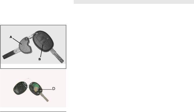
Keys (01_16, 01_17, 01_18)
Two types of keys come with the vehicle.
The red-handgrip key "A" is the "MASTER" key.
Only a single copy of this key is supplied, which is necessary to program all your other keys and for your dealer to perform some maintenance operations. For this reason it is advised that it be used only in exceptional circumstances.
The black key "B" (single copy supplied) is used for normal operations such as:
-engine start up
-open the rear glove-box and the saddle (with remote control)
Together with the two keys, you will be given a CODE CARD bearing the same code imprinted onto the two keys.
18

WARNING
LOSING THE RED KEY PREVENTS ANY REPAIRS OF THE "PIAGGIO IMMOBILIZER" SYSTEM AND THE ENGINE CONTROL UNIT.
WARNING
01_18
KEEP THE "CODE CARD" AND THE RED HANDGRIP KEY IN A SAFE PLACE (NOT ON YOUR VEHICLE).
01_19
Vehicle 1
19

1 Vehicle
Immobilizerdevice enabled indicator led (01_19)
Activation of the "PIAGGIO IMMOBILIZER" system is signalled by a flashing «A» indicator. In order to reduce battery discharge, the indicator LED turns off automatically after
48 hours of uninterrupted functioning. Should the signal led system break down in its flashing function, give information about the type of problem to an Authorised PiaggioGilera Service Centre.
Operation
Every time the starter key is removed in the "OFF" or "LOCK" position, the safety system activates the immobilizer system. Turning the key to "ON" disables the engine lock, provided that the safety system recognises the code transmitted by the key. If the code is not recognised, turn the key first to "OFF" and then to "ON"; if the lock cannot be disabled, try with the other key supplied (red-coloured). If the engine cannot be started, contact an Authorised Piaggio Service Centre, which is provided with the electronic equipment required to detect and repair the system.
When additional keys are required, please note that data storage (up to 7 keys max.) must be done on all keys, both new ones and existing ones.
Take the red-handgrip key and all the black keys supplied to an Authorised Piaggio Service Centre.
The codes of keys not submitted for the new storage procedure are deleted from the memory. Any lost keys will therefore not be enabled to start the engine.
WARNING
EACH KEY HAS ITS OWN AND UNIQUE CODE, WHICH MUST BE STORED BY THE SYSTEM CONTROL UNIT.
VIOLENT SHOCKS MAY AFFECT THE ELECTRONIC COMPONENTS OF THE KEY.
20
IF OWNERSHIP OF THE VEHICLE IS TRANSFERRED, THE RED-HANDGRIP KEY (AS WELL AS THE OTHER KEYS) AND THE "CODE CARD" MUST ALSO BE TRANSFERRED TO THE NEW OWNER.
Programming the immobilizer system
Below is described the procedure to follow for programming the PIAGGIO IMMOBILIZER system and/or for storing other key codes. The programming procedure should be carried out with the engine stop switch set to «RUN».
Procedure start - red key
Insert the red-handgrip key in the switch key (in "OFF" position) and turn it to "ON". After
1 - 3 seconds, turn the key to "OFF" again and pull it out.
Intermediate step - black key
After pulling out the red key, insert the black key within 10 seconds and promptly turn it to «ON». After 1-3 seconds, turn the key to "OFF" again and pull it out. In this way, a maximum of 7 black keys can be programmed by repeating the above procedure keeping the indicated times.
Final step - red key
After pulling out the last black key, insert the red key again and turn it to "ON" (this operation should be performed within 10 seconds of pulling out the previous key). Leave it in this position for 1 to 3 seconds and return it to the «OFF» position.
Vehicle 1
21
1 Vehicle
01_20
01_21
Proper programming check
Insert the red key disabling the transponder (i.e., tilt the key cap by 90°) and turn the key to "ON". Perform the engine start-up operation. Ensure that the engine does not start.
Insert the black key and repeat the start-up operation. Check that engine starts.
WARNING
SHOULD THE ENGINE START WITH THE RED KEY (WITH TRANSPONDER OFF), OR IN THE EVENT OF WRONG OPERATION DURING PROGRAMMING, REPEAT THE PROCEDURE FROM THE BEGINNING.
Saddle opening remote control (01_20, 01_21)
The scooter is fitted with a remote control to open the saddle. This remote control is supplied together with the keys and it has been programmed to control the opening device control unit at the manufacturing stage. If the remote control is lost, a new one can be requested and programmed at any Authorised Service Centre. The remote control is powered by inner batteries that get discharged after extended used; If the green LED turns on when the button is pressed, the remote control is working properly. You may need to replace the batteries if the remote control fails or if its range of operation is reduced. To separate the two halves of the remote control, insert the blade of a plain slot screwdriver at one point on the edge and slide it all around. When the remote control is open, remove the two batteries from the contact terminal. Install the two new CR1616 3V batteries with the positive pole facing the contact terminal.
Reassemble the remote control by pressing the two clip-on halves gently with your fingers.
To open the saddle without the remote control, follow the procedure described in the «Emergency Saddle Opening» section.
Remote control programming
Follow these steps to program the remote controls:
1. Insert the remote control key to be programmed in the steering lock key block.
22

2. Turn the key to «ON», press the button on the remote control, release the button, turn the key back to «OFF» from the «ON» position, all within 4 seconds.
3 Wait 1 to 8 seconds.
4. Repeat steps 2 and 3 for 4 times without removing the key.
The control unit confirms the programming has been successfully executed by opening the saddle.
WARNING
TO STORE THE OTHER REMOTE CONTROLS TO MEMORY, (MAXIMUM 8), YOU NEED TO REPEAT THE WHOLE PROCEDURE AGAIN. FAILURE TO CARRY OUT THESE OPERATIONS WITHIN THE INDICATED TIMES WILL RESULT IN THE AUTOMATIC CANCELLATION OF THE PROCESS FOR PROGRAMMING THE REMOTE-CONTROLLED KEYS.
WARNING
AVOID PRESSING THE REMOTE CONTROL BUTTON MORE THAN ONCE WHEN FAR AWAY FROM THE SCOOTER. THE SYNCHRONISM BETWEEN THE REMOTE CONTROL AND THE RECEIVER CAN BE IMPAIRED. SHOULD THIS BE THE CASE, REPEAT THE PROGRAMMING PROCEDURE. DO NOT KEEP THE REMOTE CONTROL IN PLACES WITH TEMPERATURES EXCEEDING 60° C THE BATTERY WILL RUN DOWN TOO QUICKLY.
WARNING
TO AVOID BATTERY DISCHARGE, THE SADDLE OPENING REMOTE CONTROL RADIO RECEIVER DEACTIVATES 7 DAYS AFTER THE LAST TIME THE VEHICLE WAS SHUT OFF.
Vehicle 1
23

JUST TURN THE KEY TO «ON» TO REACTIVATE THE RECEIVER.
Accessing the fuel tank (01_22, 01_23)
To open the fuel tank cover, set the key to «OFF» or « ON», then press and turn it clockwise.
01_22
01_23
1 Vehicle
24
01_24
01_25
01_26
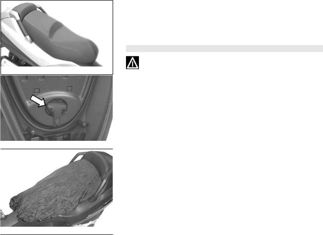
The saddle (01_24, 01_25, 01_26)
The saddle is supplied with a protection cover which may be used in case of rain.
Lift the saddle and extract the cover from its housing, then extend it over the whole length of the saddle, starting from the front-end; do not over stretch the cover to avoid tearing the material; close the saddle.
CAUTION
DO NOT USE THE VEHICLE WITHOUT THE PROTECTION COVER.
Vehicle 1
25
1 Vehicle
01_27
Opening the saddle to access the helmet compartment by remote control (01_27)
When the key is in «LOCK» or «OFF» position you can open the saddle using the remote control. The saddle cannot be opened only when the key is set to "ON".
WARNING
OBJECTS INAPPROPRIATELY ARRANGED INSIDE THE HELMET COMPARTMENT MAY DEFORM THE SADDLE CAUSING THE COURTESY LIGHT TO REMAIN ON AND THIS WILL DISCHARGE THE BATTERY. IN ANY CASE, THE WARNING LIGHT "I" ON THE INSTRUMENT PANEL SIGNALS IF THE LIGHT IS ON OR OFF.
26

01_28
01_29
WARNING
THE REMOTE CONTROL OPERATES WITHIN A DISTANCE OF ABOUT 3/5 METRES WITH FULLY CHARGED BATTERIES. WHEN YOU ARE NEAR THE SCOOTER, HANDLE THE REMOTE CONTROL CAREFULLY SO AS TO AVOID UNINTENTIONAL OPENING OF THE SADDLE. REFER TO THE «OPENING THE SADDLE WITH REMOTE CONTROL» SECTION TO REPLACE BATTERIES.
Opening the saddle to access the helmet compartment in an emergency (01_28, 01_29)
If the remote control battery or the vehicle battery is discharged, follow these steps to open the saddle:
1.Open the rear case with the key switch
2.Softly press with your hand on the point shown in the photo and in the sense indicated by the arrow inside the helmet compartment until the saddle closing device springs
Vehicle 1
27

1 Vehicle
01_30
01_31
01_32
Opening of top box (01_30)
With the switch set to «OFF» or «ON», press the key and turn it anticlockwise, towards position «4».
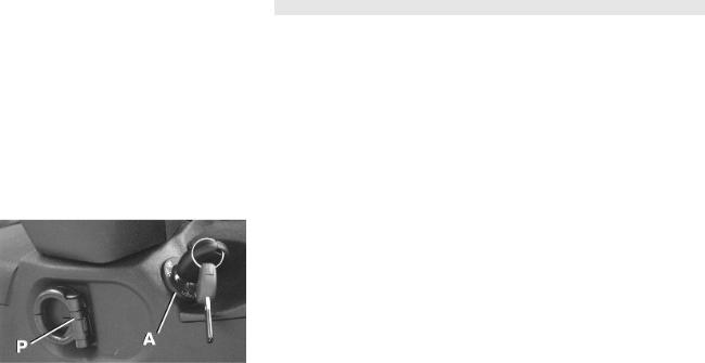
Identification (01_31, 01_32)
The identification registration numbers consist of a prefix stamped on the chassis and engine "B" respectively, followed by a number. These numbers must always be indicated on spare parts requests. To read the chassis number, remove the relevant port
"A" in the helmet compartment. We recommend checking that the chassis registration number stamped on the vehicle corresponds with that on the vehicle documentation.
CAUTION
BE REMINDED THAT ALTERING IDENTIFICATION REGISTRATION NUMBERS CAN LEAD TO SERIOUS PENAL SANCTIONS (IMPOUNDING OF THE VEHICLE, ETC.).
28

MP3 250 i.e.
Chap. 02
Use
29

Checks
Before using the vehicle, check:
1. There is enough fuel in the fuel tank.
2. The correct fluid level for front and rear brakes.
3. That tyres are properly inflated.
4. The correct functioning of tail lights, headlamp, turn indicators, stop light and license plate light.
5. The correct functioning of front and rear brakes.
6. The oil level in the gearcase.
7. The engine oil level.
8. The coolant level.
02_01
2 Use
30
 Loading...