


MP3 400 i.e.

SERVICE STATION MANUAL
664502(IT)-664503(EN)-664504(FR)-664505
(DE)-664506(ES)-664507(PT)-664508(NL)-664509
(EL)
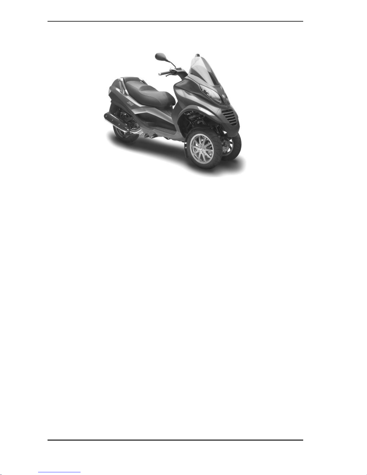
MP3 400 i.e.

SERVICE STATION
MANUAL
MP3 400 i.e.
The descriptions and illustrations given in this publication are not binding. While the basic specifications
as described and illustrated in this manual remain unchanged, PIAGGIO-GILERA reserves the right, at
any time and without being required to update this publication beforehand, to make any changes to
components, parts or accessories, which it considers necessary to improve the product or which are
required for manufacturing or construction reasons.
Not all versions shown in this publication are available in all Countries. The availability of single versions
should be checked at the official Piaggio sales network.
"© Copyright 2007 - PIAGGIO & C. S.p.A. Pontedera. All rights reserved. Reproduction of this publication
in whole or in part is prohibited."
PIAGGIO & C. S.p.A. - After-Sales
V.le Rinaldo Piaggio, 23 - 56025 PONTEDERA (Pi)
SERVICE STATION MANUAL
MP3 400 i.e.
This service station manual has been drawn up by Piaggio & C. Spa to be used by the workshops of
Piaggio-Gilera dealers. It is assumed that the user of this manual for maintaining and repairing Piaggio
vehicles has a basic knowledge of mechanical principles and vehicle repair technique procedures. Any
significant changes to vehicle characteristics or to specific repair operations will be communicated by
updates to this manual. Nevertheless, no mounting work can be satisfactory if the necessary equipment
and tools are unavailable. It is therefore advisable to read the sections of this manual concerning special
tools, along with the special tool catalogue.
N.B. Provides key information to make the procedure easier to understand and carry out.
CAUTION Refers to specific procedures to carry out for preventing damages to the vehicle.
WARNING Refers to specific procedures to carry out to prevent injuries to the repairer.
Personal safety Failure to completely observe these instructions will result in serious risk of personal
injury.
Safeguarding the environment Sections marked with this symbol indicate the correct use of the vehicle
to prevent damaging the environment.
Vehicle intactness The incomplete or non-observance of these regulations leads to the risk of serious
damage to the vehicle and sometimes even the invalidity of the guarantee.

INDEX OF TOPICS
CHARACTERISTICS CHAR
TOOLING TOOL
MAINTENANCE MAIN
TROUBLESHOOTING TROUBL
ELECTRICAL SYSTEM ELE SYS
ENGINE FROM VEHICLE ENG VE
ENGINE ENG
INJECTION INJEC
SUSPENSIONS SUSP
BRAKING SYSTEM BRAK SYS
COOLING SYSTEM COOL SYS
CHASSIS CHAS
PRE-DELIVERY PRE DE
TIME TIME


INDEX OF TOPICS
CHARACTERISTICS CHAR

This section describes the general specifications of the vehicle.
Rules
This section describes general safety rules for any maintenance operations performed on the vehicle.
Safety rules
- If work can only be done on the vehicle with the engine running, make sure that the premises are wellventilated, using special extractors if necessary; never let the engine run in an enclosed area. Exhaust
fumes are toxic.
- The battery electrolyte contains sulphuric acid. Protect your eyes, clothes and skin. Sulphuric acid is
highly corrosive; in the event of contact with your eyes or skin, rinse thoroughly with abundant water
and seek immediate medical attention.
- The battery produces hydrogen, a gas that can be highly explosive. Do not smoke and avoid sparks
or flames near the battery, especially when charging it.
- Fuel is highly flammable and it can be explosive given some conditions. Do not smoke in the working
area, and avoid open flames or sparks.
- Clean the brake pads in a well-ventilated area, directing the jet of compressed air in such a way that
you do not breathe in the dust produced by the wear of the friction material. Even though the latter
contains no asbestos, inhaling dust is harmful.
Maintenance rules
- Use original PIAGGIO spare parts and lubricants recommended by the Manufacturer. Non-original or
non-conforming spares may damage the vehicle.
- Use only the appropriate tools designed for this vehicle.
- Always use new gaskets, sealing rings and split pins upon refitting.
- After removal, clean the components using non-flammable or low flash-point solvent. Lubricate all the
work surfaces except the tapered couplings before refitting.
- After refitting, make sure that all the components have been installed correctly and work properly.
- For removal, overhaul and refit operations use only tools with metric measures. Metric bolts, nuts and
screws are not interchangeable with coupling members with English measurement. Using unsuitable
coupling members and tools may damage the scooter.
- When carrying out maintenance operations on the vehicle that involve the electrical system, make
sure the electric connections have been made properly, particularly the ground and battery connections.
Characteristics MP3 400 i.e.
CHAR - 2

Vehicle identification
Chassis prefix (A)
ZAPM59101
Engine prefix (B):
M474M
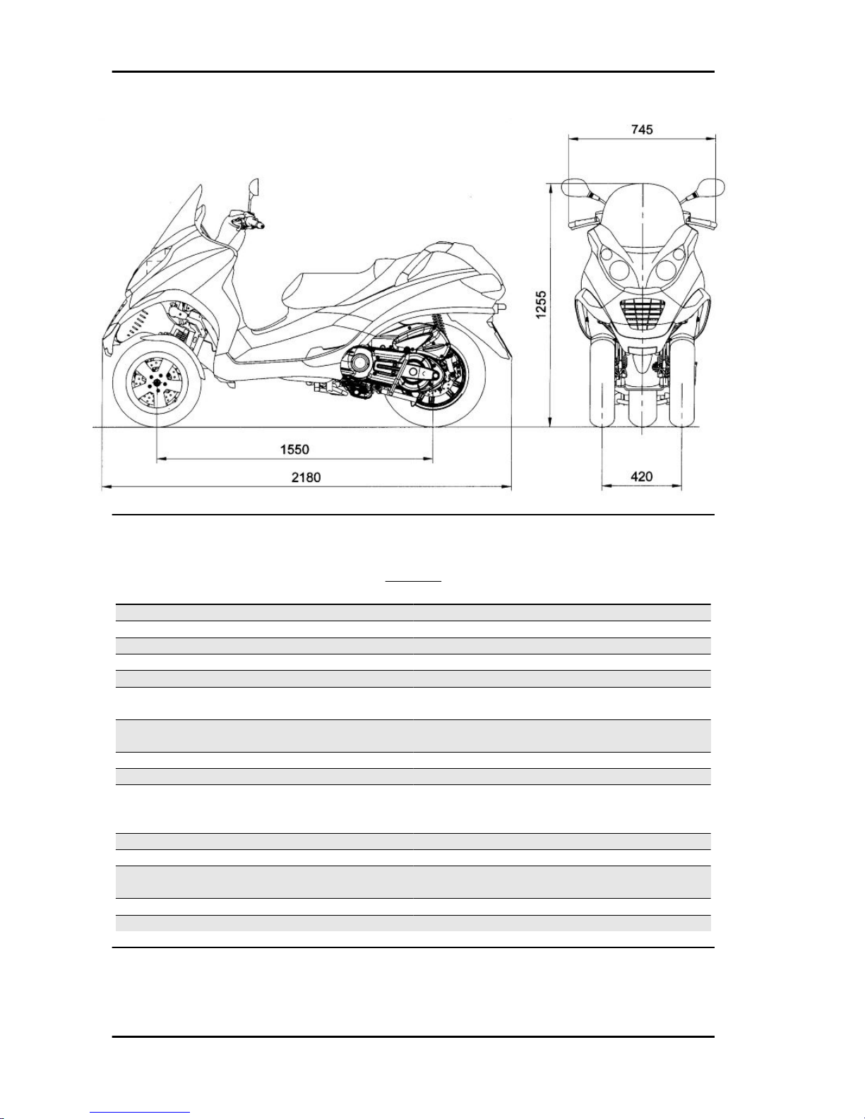
Dimensions and mass
WEIGHTS AND DIMENSIONS
Specification Desc./Quantity
Kerb weight 253 ± 5 kg
Maximum weight allowed 445 kg
Maximum height 1.225 mm
Width 745 mm
Wheelbase 1.550 mm
Length 2.180 mm
Track 420 mm
MP3 400 i.e. Characteristics
CHAR - 3
Engine
ENGINE
Specification Desc./Quantity
Type Single-cylinder, 4-stroke
Cubic capacity 399 cm³
Bore x stroke 85.8 X 69 mm
Compression ratio 10.6 ± 0.5 : 1
Engine idle speed 1,500 ± 100 rpm
Timing system Four valves, single overhead camshaft, chain driv-
en.
Valve clearance Inlet: 0.15 mm
Outlet: 0.15 mm
MAX. power 24 kW at 7,250 rpm
MAX torque 38 Nm at 5.250 rpm
Lubrication Engine lubrication with trochoidal pump (inside the
crankcase), oil filter and pressure adjustment by-
pass.
Lubrication pressure 3.5 ÷ 4 bar
Minimum lubrication pressure (100° C) 0.8 bar
Fuel supply Electronic injection with Ø38-mm throttle body and
electric fuel pump.
Cooling Forced coolant circulation system.
Fuel Unleaded petrol (95 RON)
Characteristics MP3 400 i.e.
CHAR - 4

Transmission
TRANSMISSION
Specification Desc./Quantity
Transmission Automatic expandable pulley variator with torque
server, V belt, automatic clutch.
Final reduction
Gear reduction unit in oil bath.
Capacities
CAPACITY
Specification Desc./Quantity
Engine oil 1.7 l
Transmission oil 250 cm³
Cooling system fluid ~ 1.8 l
Fuel tank (reserve) ~ 12 l (~2 l)
Electrical system
ELECTRICAL SYSTEM
Specification Desc./Quantity
Start-up Electric
Ignition Electronic, inductive, high efficiency ignition, inte-
grated with the injection system, with variable ad-
vance and separate HV coil.
Ignition advance Three-dimensional map managed by control unit
Spark plug CHAMPION RG 6 YC
Alternative spark plug NGK CR7EKB
Battery 12 V / 14 Ah, SEALED BATTERY
Generator In alternating current
Frame and suspensions
FRAME AND SUSPENSIONS
Specification Desc./Quantity
Chassis Tubular and sheet steel
Front suspension The tilt mechanism is composed of an articulated
parallelogram suspension with die-cast aluminium
control arms and two side headstocks plus shock
absorbers with hydraulic locking system.
Front suspension travel 85 mm
Rear suspension Two double-acting shock absorbers, adjustable to
four positions at preloading.
Rear suspension travel 110 mm
MP3 400 i.e. Characteristics
CHAR - 5

Brakes
BRAKES
Specification Desc./Quantity
Front brake Ø 240 mm double disk with hydraulic control acti-
vated by the handlebar right-hand lever.
Rear brake disc brake, diameter 240 mm, with hydraulic servo
operated from the handlebar with the left-hand lev-
er.
Wheels and tyres
WHEELS AND TYRES
Specification Desc./Quantity
Wheel rim type Light alloy rims.
Front rim 12'' x 3.00
Rear rim 14'' x 4.50
Front tyre Tubeless 120/70-12" 51S or 51P
Rear tyre Tubeless 140/70 - 14" 68S or 68P reinf
Front tyre pressure (with passenger) 1.6 bar (1.8 bar)
Rear tyre pressure (with passenger) 2.4 bar (2.6 bar)
Tightening Torques
STEERING
Name Torque in Nm
Steering lower ring nut (central headstock) 22 ÷ 27 loosen by 90°
Steering upper ring nut (central headstock) 27 ÷ 33
Handlebar fixing screw 50 ÷ 55
Fixing screws for handlebar control assembly U-
bolts
7 ÷ 10
CHASSIS
Name Torque in Nm
Swinging arm set screw bushing 5 ÷ 7
Engine arm bolt - frame arm 32.5 ÷ 40
Swinging arm set screw bushing nut 54 ÷ 60
Engine-swinging arm bolt 98 ÷ 118
Frame-swinging arm bolt 54 ÷ 60
Centre stand bolt 31 ÷ 39
FRONT SUSPENSION
Name Torque in Nm
Shock absorber lower clamp 19 ÷ 26
Upper shock absorber clamp 19 ÷ 29
Front wheel fixing screws 19 ÷ 24
Steering arm bolt nut 20 ÷ 25
Tilt calliper fixing screws 20 ÷ 25
Front wheel shaft 74 ÷ 88
Arm coupling screws 45 ÷ 50
Characteristics MP3 400 i.e.
CHAR - 6

Name Torque in Nm
Screws fixing arms to side headstocks 45 ÷ 50
Screws fixing arms to central headstock 45 ÷ 50
Screws fixing the half-arm coupling flange 20 ÷ 25
Fixing screws for tilt locking disc section 20 ÷ 25
Side headstock upper ring nut 20 - 24
Side headstock lower ring nut 12 ÷ 15
Screw fixing sliding stem to shock absorber 45 ÷ 50
Clamp for sliding stem locking device 6.5 ÷ 10.5
Fixing nuts for constant-velocity universal joints 18 ÷ 20
Potentiometer to anti-tilting device clamp 8 ÷ 10
Electric motor to anti-tilting device clamp 11 ÷ 13
Clamp fixing pump bolt to anti-tilting device 11 ÷ 13
Pump to anti-tilting device clamp 11 ÷ 13
Pressure switch to distribution frame 18 ÷ 20
Sensor to tilt gripper clamp 2.5 ÷ 2.9
Pipe terminals to fifth wheel check spring 7 ÷ 11
Joint to anti-tilting device pump 20 ÷ 25
Lower fitting for shock absorber sliding locking
clamp pipes
20 ÷ 25
Upper fitting for shock absorber sliding locking
clamp pipes
20 ÷ 25
REAR SUSPENSION
Name Torque in Nm
Upper shock absorber clamp 33 ÷ 41
Shock absorber lower clamp 33 ÷ 41
Shock absorber-crankcase attachment bracket 20 ÷ 25
Rear wheel axle 104 ÷ 126
Muffler arm clamping screws 27 ÷ 30
FRONT BRAKE
Name Torque in Nm
Calliper coupling screw 22 ÷ 27
Oil bleed screw 8÷12
Disc tightening screw (°) 5 - 6
Brake fluid pump - hose fitting 16 ÷ 20
Brake fluid pipe-calliper fitting 20 ÷ 25
Screw tightening calliper to the support 20 ÷ 25
Calliper upper pipe fitting 20 ÷ 25
REAR BRAKE
Name Torque in Nm
Oil bleed screw 12÷16
Rear brake disc screws(°) 5 ÷ 6.5
Rear brake calliper-pipe fitting 20 ÷ 25
Rigid / flexible pipe fitting 13 ÷ 18
Rear brake pump-pipe fitting 16 ÷ 20
Rear brake calliper fixing screws 20 ÷ 25
pad fastening pin screws 20 ÷ 25
MP3 400 i.e. Characteristics
CHAR - 7

REAR BRAKE
Product Description Specifications
(°) Loctite 243 Medium strength threadlock Apply LOCTITE 243 medium-
strength threadlock
MUFFLER
Name Torque in Nm
Muffler heat guard fixing screw 4 ÷ 5
Screw for fixing muffler to the support arm 20 ÷ 25
Lambda probe clamp on exhaust manifold 40 ÷ 50
Exhaust manifold-muffler joint clamp 12 ÷ 13
Manifold - muffler diaphragm tightening clamp 16 ÷ 18
LUBRICATION
Name Torque in Nm
Oil pump cover screws 0.7 ÷ 0.9
Screws fixing oil pump to the crankcase 5 - 6
THERMAL UNIT AND TIMING SYSTEM
Name Torque in Nm
Spark plug 12 ÷ 14
Head fixing stud bolts: ***
Head fixing nuts 10 - 12
Exhaust / intake head fixing nuts: 10 - 12
Head lubrication control jet 5 - 7
coolant temperature sensor: 10 - 12
Lambda probe on exhaust manifold 10 - 12
injector fixing screw 3 ÷ 4
Counterweight screw 7 ÷ 8.5
Tensioner sliding block fixing screw: 10 - 14
Rpm timing sensor fixing screw: 3 - 4
Valve lifter mass stop bell fixing screws: 30 - 35
Inlet manifold screws 11 ÷ 13
Tappet cover fixing screws: 7 - 9
Throttle body fixing screws 11 ÷ 13
Head fixing screws 10 - 12
Camshaft retaining bracket screws: 4 ÷ 6
Tightener screw: 5 - 6
Tightener fastening screws: 11 ÷ 13
*** Apply a preliminary torque of 7 Nm in a crossed sequence. - Tighten by 90° in a crossed sequence. - Tighten again by 90° in
a crossed sequence.
TRANSMISSION COVER
Name Torque in Nm
Driven pulley nut 92 - 100
Drive pulley nut 160 - 175
Anti-vibration roller screw 16.7 - 19.6
M8 retainers for transmission cover 23 - 26
M6 retainer 11 ÷ 13
Anti-vibration roller retainer 17 - 19
Clutch ring nut 65 - 75
Air conveyor screws 11 ÷ 12
Water pump cover screws 3 ÷ 4
Characteristics MP3 400 i.e.
CHAR - 8

Name Torque in Nm
Outside transmission cover screws 7 ÷ 9
Flywheel cover screws 11 - 13
FLYWHEEL COVER
Name Torque in Nm
Chain guide sliding block retain plate fastening
screws
3 ÷ 4
Flywheel fixing nut 115 - 125
Stator retainers 8 - 10
Blow-by recovery duct fixing screws 3 - 4
Screw fixing freewheel to flywheel 13 ÷ 15
Stator cable harness guide bracket screws 3 - 4
Supporting screws with bulkhead 0.3 - 0.4
Minimum oil pressure sensor 12 ÷ 14
Water pump impeller 4 ÷ 5
CRANKCASE AND CRANKSHAFT
Name Torque in Nm
Countershaft fixing nut 25 - 29
Engine oil filter 12 - 16
Engine oil drainage plug 24 ÷ 30
Engine-crankcase coupling screws 11 ÷ 13
Oil pump screws 5 - 6
Gear mounting on crankshaft screws 10 -12
Bulkhead screws for oil pump housing cover 8 - 10
COOLING
Name Torque in Nm
Water pump rotor cover 3 ÷ 4
Thermostat cover screws 3 ÷ 4
Bleed screw: 3
Overhaul data
Assembly clearances
Cylinder - piston assy.
MP3 400 i.e. Characteristics
CHAR - 9
HEIGHT AT WHICH THE DIAMETER SHOULD BE MEASURED
Specification Desc./Quantity
A 43.2 mm
B 43 mm
CYLINDER- PISTON
Specification Desc./Quantity
Cylinder diameter C 85.8 - +0.018 -0.01 mm
Piston Ø P 85.768 ± 0.014 mm
CYLINDER - PISTON
COUPLING CATEGORIES
Name Initials Cylinder Piston Play on fitting
Cylinder- Piston A 85.790÷85.797 85.754÷85.761 0.029÷0.043
Cylinder- Piston B 85.797÷85.804 85.761 ÷ 85.768 0.029÷0.043
Cylinder- Piston C 85.804÷85.811 85.768÷85.775 0.029÷0.043
Cylinder- Piston D 85.811÷85.818 85.775÷85.782 0.029÷0.043
CATEGORIES OF COUPLING
N.B.
THE PISTON MUST BE INSTALLED WITH THE ARROW FACING TOWARDS THE EXHAUST SIDE,
THE PISTON RINGS MUST BE INSTALLED WITH THE WORD «TOP» OR THE STAMPED MARK
FACING UPWARDS.
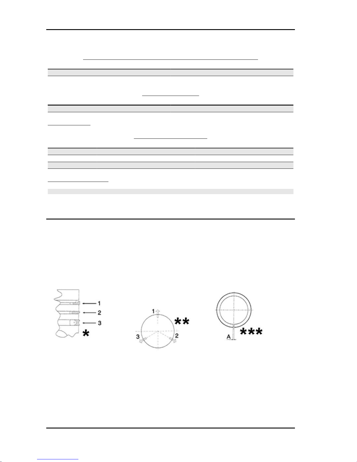
Piston rings
*Fit rings «2» and «3» with the word «TOP» facing upwards.
** Position the openings in the rings as shown here.
***Value «A» of sealing ring inside the cylinder.
Characteristics MP3 400 i.e.
CHAR - 10

Check the size of the sealing ring opening:
Compression ring: 0.15 ÷ 0.35 mm. Max. value 0.5 mm
Oil scraper ring: 0.25 ÷ 0.50 mm. Max. value 0.65 mm
Oil scraper ring: 0.25 ÷ 0.50 mm. Max. value 0.65 mm
Rings/housing coupling clearances:
Carefully clean the sealing ring housings.
Place a thickness gauge between the ring and the
housing as shown in the drawing and check the
coupling clearances.
Top ring Standard coupling clearance:
0.01÷0.06 mm
Maximum clearances allowed after use: 0.10
mm
Intermediate ring Standard coupling clearance:0.02÷0.07 mm
Maximum clearances allowed after use: 0.10
mm
Oil scraper ring Standard coupling clearance:
0.01÷0.06 mm
Maximum clearances allowed after use: 0.10
mm
Replace the piston if clearances exceed the maximum limits specified in the table.
Crankcase - crankshaft - connecting rod
Crankcase / countershaft coupling
Besides considering it should match the crankshaft, the crankcase is chosen according to the centre
to centre distance between the seat of the crankshaft and that of the contra-rotating shaft.
Both the centre to centre distance and the pair of gears driving the contra-rotating shaft are divided into
two types (A and B) to be matched (A with A and B with B).
This selection is useful to keep the difference between the working distance of the gears and their
distance without clearance at a given value in order to avoid abnormal noise.
TYPE A
Specification Desc./Quantity
Centre to centre distance of the gears without
clearance
76.937 ÷ 76.867
Centre to centre distance on the crankcase 77.022 ÷ 76.992
MP3 400 i.e. Characteristics
CHAR - 11

TYPE B
Specification Desc./Quantity
Centre to centre distance of the gears without
clearance
76.907 ÷ 76.837
Centre to centre distance on the crankcase 76.992 ÷ 76.962
The gears with centre to centre distance without clearance between 76.867 and 76.907 are considered
universal and can be fitted to either crankcase type.
Either the pair of gears or the crankcase is identified with the letter referring to the type (on the crankcase, this mark is found at the cylinder mouth, flywheel side).
Characteristic
crankshaft / crankcase axial clearance:
0.1 ÷ 0.405 mm
Diameter of crankshaft bearings.
Measure the capacity on both axes x-y.
CRANKSHAFT
Specification Desc./Quantity
Cat. 1 Standard diameter: 40.020÷40.026
Cat. 2 Standard diameter: 40.026÷40.032
Characteristics MP3 400 i.e.
CHAR - 12

Crankshaft alignment
Specific tooling
020335Y Magnetic support for dial gauge
MAX. ADMISSIBLE DISPLACEMENT
Specification Desc./Quantity
A = 0.15 mm
B = 0.010 mm
C = 0.010 mm
D = 0.10 mm
AXIAL CLEARANCE BETWEEN CRANKSHAFT AND CONNECTING ROD
Name Description Dimensions Initials Quantity
Transmission-side
shoulder
1±0.025 A D = 0.20 - 0.50
Half-shaft, trans-
mission side
20-0.05 B D = 0.20 - 0.50
Connecting rod 22 -0.10 -0.15 C D = 0.20 - 0.50
Flywheel-side
shoulder
1.8±0.025 F D = 0.20 - 0.50
Flywheel side half-
shaft
19.6 -0.05 E D = 0.20 - 0.50
Complete crank-
shaft
65 +0.10 -0.05 G D = 0.20 - 0.50
MP3 400 i.e. Characteristics
CHAR - 13
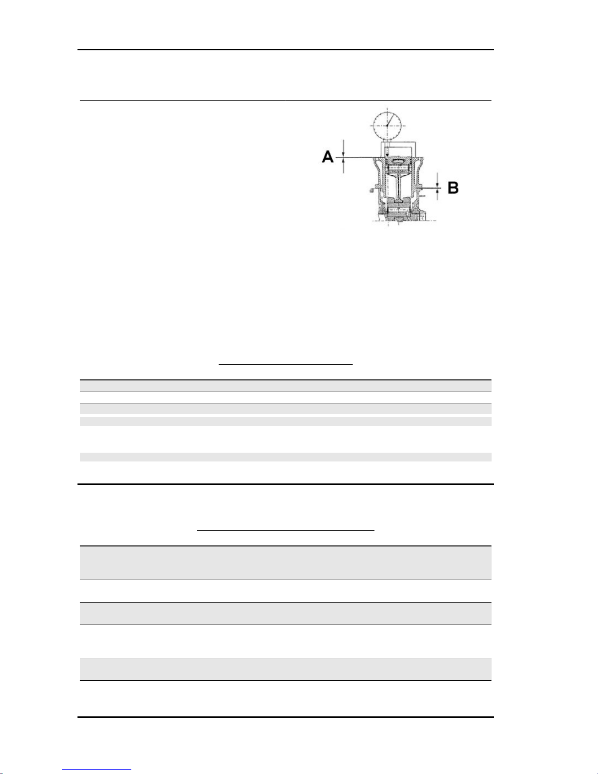
Slot packing system
Shimming system for keeping the compression ratio
DISTANCE «A» IS A PROTRUSION OR RECESS VALUE OF THE PISTON CROWN WITH
RESPECT TO THE CYLINDER PLANE.
DISTANCE «A» HELPS DETERMINE THE
THICKNESS OF GASKET «B» THAT HAS TO
BE FITTED TO THE CYLINDER HEAD IN ORDER TO RESTORE COMPRESSION RATIO.
BASE GASKET «B» MUST BE THICKER THE
MORE THE PLANE FORMED BY THE PISTON
TOP PROTRUDES FROM THE PLANE
FORMED BY THE CYLINDER HEAD. ON THE
OTHER HAND, THE MORE THE PISTON TOP IS
RECESSED INTO THE CYLINDER TOP PLANE,
THE SMALLER THE GASKET THICKNESS.
Characteristic
Compression ratio
10.6 ± 0.5 : 1
BASE GASKET THICKNESS
Name Measure A Thickness
«A» MEASURE TAKEN - 0.185 - - 0.10 0.4 ± 0.05
«A» MEASURE TAKEN - 0.10 - + 0.10 0.6 ± 0.05
«A» MEASURE TAKEN + 0.10 ÷ + 0.185 0.8 ± 0.05
N.B.
VALUES INDICATED WITH «-» REFER TO PISTON CROWN RECESSES WITH RESPECT TO THE
CYLINDER PLANE.
N.B.
DISTANCE «A» MUST BE MEASURED WITHOUT ANY GASKET FITTED AT «B»
Products
RECOMMENDED PRODUCTS TABLE
Product Description Specifications
AGIP ROTRA 80W-90 Rear hub oil SAE 80W/90 Oil that exceeds the
requirements of API GL3 specifi-
cations
AGIP CITY HI TEC 4T Oil to lubricate flexible transmis-
sions (throttle control)
Oil for 4-stroke engines
AGIP FILTER OIL Oil for air filter sponge Mineral oil with specific additives
for increased adhesiveness
AGIP GP 330 Grease for brake levers, throttle White calcium complex soap-
based spray grease with NLGI 2;
ISO-L-XBCIB2
AGIP CITY HI TEC 4T Engine oil SAE 5W-40, API SL, ACEA A3,
JASO MA Synthetic oil
AGIP BRAKE 4 Brake fluid FMVSS DOT4 Synthetic fluid
Characteristics MP3 400 i.e.
CHAR - 14

Product Description Specifications
SPECIAL AGIP PERMANENT
fluid
coolant Monoethylene glycol-based anti-
freeze fluid, CUNA NC 956-16
MP3 400 i.e. Characteristics
CHAR - 15

Characteristics MP3 400 i.e.
CHAR - 16

INDEX OF TOPICS
TOOLING TOOL
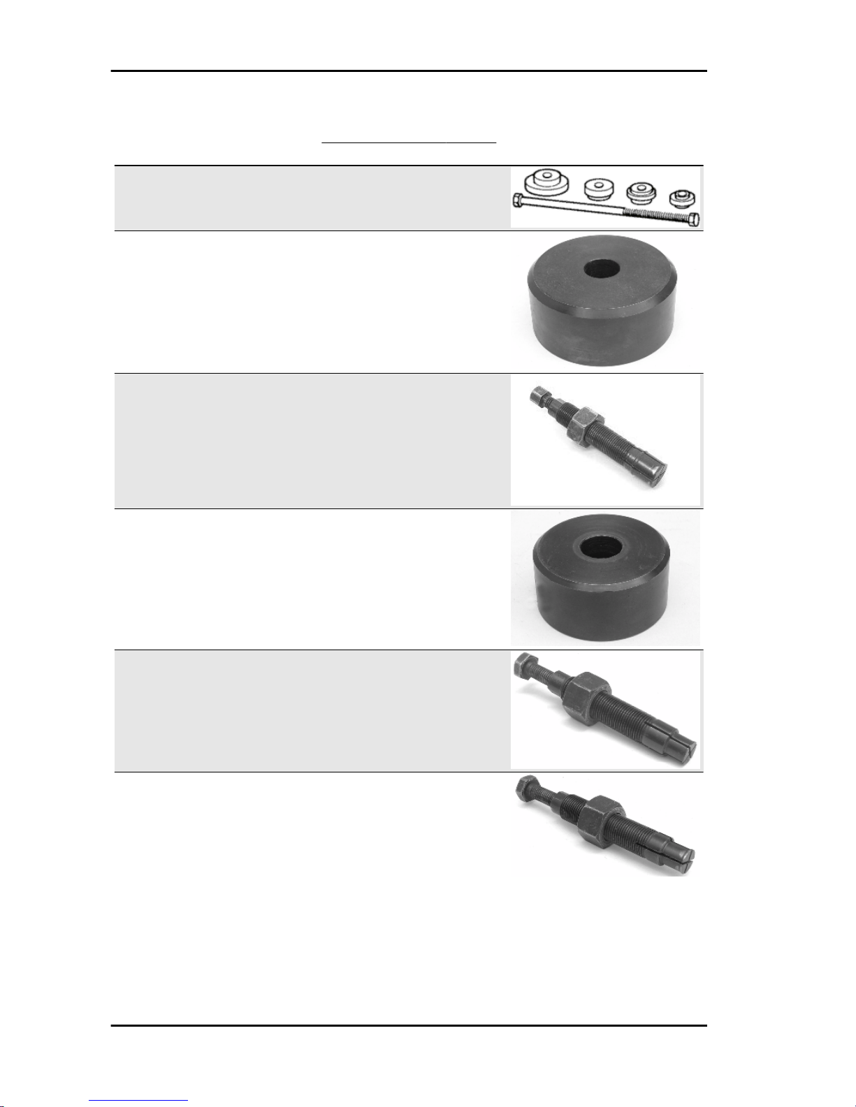
SPECIFIC TOOLS CORRECT
Stores code Description
001330Y Tool for fitting steering seats
001467Y002 Driver for OD 73 mm bearing
001467Y006 Pliers to extract 20 mm bearings
001467Y007 Driver for OD 54 mm bearing
001467Y008 Pliers to extract 17 mm ø bear-
ings
001467Y014 Pliers to extract ø 15-mm bear-
ings
Tooling MP3 400 i.e.
TOOL - 2

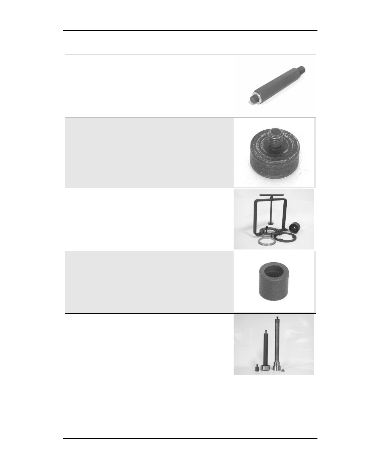
Stores code Description
001467Y031 Bell
001467Y034 Extraction pliers for ø 15 mm
bearings
001467Y035 Belle for OD 47-mm bearings
002465Y Pliers for circlips
006029Y Punch for fitting fifth wheel seat
on steering tube
020004Y Punch for removing fifth wheels
from headstock
020055Y Wrench for steering tube ring nut
020150Y Air heater support
MP3 400 i.e. Tooling
TOOL - 3

Stores code Description
020151Y Air heater
020193Y Oil pressure gauge
020201Y Spacer bushing driving tube
020262Y Crankcase splitting strip
020306Y Punch for assembling valve seal
rings
020329Y MityVac vacuum-operated pump
020330Y Stroboscopic light for timing con-
trol
Tooling MP3 400 i.e.
TOOL - 4

Stores code Description
020331Y Digital multimeter
020333Y Single battery charger
020334Y Multiple battery charger
020335Y Magnetic support for dial gauge
020357Y 32 x 35 mm adaptor
020358Y 37x40-mm adaptor
020359Y 42x47-mm adaptor
MP3 400 i.e. Tooling
TOOL - 5

Stores code Description
020360Y Adaptor 52 x 55 mm
020364Y 25-mm guide
020376Y Adaptor handle
020382Y012 bush (valve removing tool)
020412Y 15 mm guide
020424Y Driven pulley roller casing fitting
punch
020431Y Valve oil seal extractor
Tooling MP3 400 i.e.
TOOL - 6
Stores code Description
020434Y Oil pressure control fitting
020439Y 17 mm guide
020444Y Tool for fitting/ removing the driv-
en pulley clutch
020456Y Ø 24 mm adaptor
020458Y Puller for lower bearing on steer-
ing tube
MP3 400 i.e. Tooling
TOOL - 7

Stores code Description
020459Y Punch for fitting bearing on steer-
ing tube
020460Y Scooter diagnosis and tester
020467Y Flywheel extractor
020468Y Piston fitting ring
020469Y Reprogramming kit for scooter
diagnosis tester
Tooling MP3 400 i.e.
TOOL - 8
 Loading...