


Vespa Granturismo

Vespa would like to thank you
for choosing one of its products. We have prepared this booklet to help you to get the very best from your scooter. Please read it carefully before riding
the vehicle for the first time. It contains information, tips and precautions for using your vehicle. It also describes features, details and devices to assure
you that you have made the right choice. We believe that if you follow our suggestions, you will soon get to know your new vehicle and use it for a long
time at full satisfaction. This booklet forms an integral part of the vehicle; should the vehicle be sold, it must be transferred to the new owner.
Vespa GTS 125

The instructions given in this booklet are intended to provide a clear, simple guide to using your scooter; details are also given of routine maintenance
procedures and regular checks that should be carried out on the vehicle at an Authorised PIAGGIO Dealer or Service Centre. The booklet also
contains instructions for simple repairs. Any operations not specifically described in this booklet require the use of special tools and/or particular technical
knowledge: to carry out these operations refer to any authorised PIAGGIO Dealer of Service Centre.
2

Personal safety
Failure to completely observe these instructions will result in serious risk of personal
Safeguarding the environment
Sections marked with this symbol indicate the correct use of the vehicle to prevent dam-
aging the environment.
The incomplete or non-observance of these regulations leads to the risk of serious
damage to the vehicle and sometimes even the invalidity of the guarantee.
The signs that you see on this page are very important. They are used to highlight those
parts of the booklet that should be read with particular care. As you can see, each sign
consists of a different graphic symbol, making it quick and easy to locate the various
topics.
injury.
Vehicle intactness
3

4

INDEX
VEHICLE...................................................................................... 7
Dashboard................................................................................ 8
Analogue instrument panel....................................................... 8
Clock......................................................................................... 9
Key switch................................................................................. 9
Locking the steering wheel.................................................... 10
Releasing the steering wheel................................................ 10
Switch direction indicators........................................................ 10
Horn button............................................................................... 11
Light switch............................................................................... 11
Start-up button.......................................................................... 12
Engine stop button.................................................................... 12
The immobilizer system............................................................ 12
Keys...................................................................................... 13
Immobilizerdevice enabled indicator led............................... 14
Operation............................................................................... 14
Programming the immobilizer system................................... 15
Accessing the fuel tank............................................................. 16
Opening the saddle............................................................... 17
Identification.............................................................................. 18
Rear top box opening................................................................ 19
USE.............................................................................................. 21
Checks...................................................................................... 22
Refuelling.................................................................................. 22
Tyre pressure............................................................................ 24
Shock absorbers adjustment.................................................... 25
Running in................................................................................. 26
Starting up the engine............................................................... 26
Precautions........................................................................... 27
Difficult start up......................................................................... 28
Stopping the engine.................................................................. 28
Stand......................................................................................... 29
Automatic transmission............................................................. 29
Safe driving............................................................................... 30
Rear rack.................................................................................. 32
MAINTENANCE........................................................................... 33
Engine oil level.......................................................................... 34
Engine oil level check............................................................ 35
Engine oil top-up................................................................... 35
Warning light (insufficient oil pressure)................................. 35
Engine oil change.................................................................. 36
Hub oil level.............................................................................. 37
Tyres......................................................................................... 39
Spark plug dismantlement........................................................ 40
Removing the air filter............................................................... 41
Secondary air system............................................................... 42
Cooling fluid level...................................................................... 43
Checking the brake oil level...................................................... 45
Battery....................................................................................... 46
Use of a new battery............................................................. 47
Long periods of inactivity.......................................................... 48
Fuses........................................................................................ 49
Front light group........................................................................ 54
Headlight adjustment............................................................. 55
Front direction indicators........................................................... 56
Rear optical unit........................................................................ 57
Rear turn indicators................................................................... 57
Rear-view mirrors...................................................................... 58
Idle adjustment.......................................................................... 58
Front and rear disc brake.......................................................... 59
Puncture.................................................................................... 60
Periods of inactivity................................................................... 61
Cleaning the vehicle.................................................................. 61
TECHNICAL DATA...................................................................... 67
Kit equipment............................................................................ 71
SPARE PARTS AND ACCESSORIES........................................ 73
5

Warnings................................................................................... 74
PROGRAMMED MAINTENANCE............................................... 77
Scheduled maintenance table................................................... 78
6

Vespa GTS 125
Chap. 01
Vehicle
7
01_01
01_02
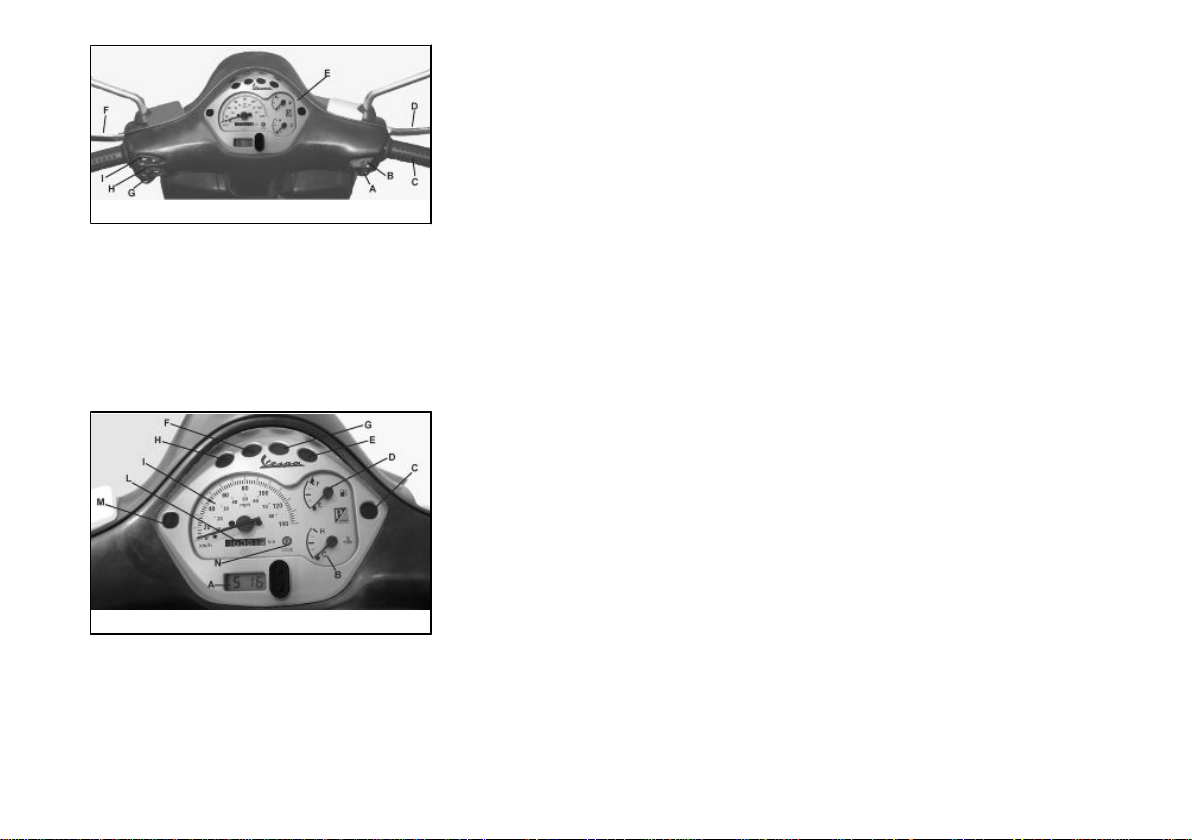
Dashboard (01_01)
A = Starter button
B = Engine block Run-Off switch
C = Throttle control
D = Front brake lever
E = Instrument panel
F = Rear brake control lever
G = Horn button
H = Turn indicator switch
I = Light switch
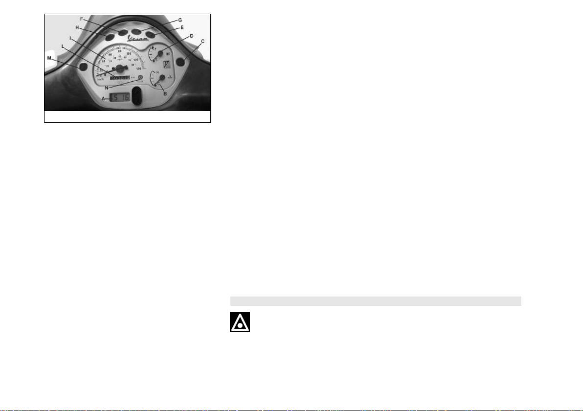
Analogue instrument panel (01_02)
A = Digital clock with calendar
B = Cooling liquid temperature gauge
C = Right turn indicator warning light
D = Fuel gauge
E = Headlight warning light
F = Low oil pressure warning light
G = High-beam warning light
H = Low fuel warning light
I = Speedometer
L = Odometer
8
1 Vehicle
01_03
M = Left turn indicator warning light
N = Antitheft device led (immobilizer)
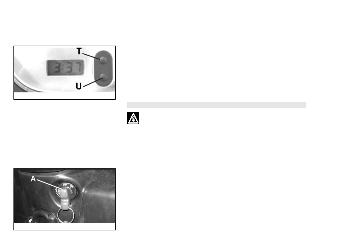
Clock (01_03)
Hours and minutes are displayed in a 1 to 12, AM or PM, format on the instrument
panel.
Operating the function selection switch «T» month, day and seconds can be seen
besides hours and minutes. In order to adjust the above mentioned functions, operate
button «U». The digital clock is powered by a battery (battery life is about 2 years); lift
the whole instrument panel to replace the battery. It is advisable to take your vehicle
to an Authorised Service Centre for this operation.
WARNING
DEAD BATTERIES ARE HARMFUL TO THE ENVIRONMENT. THEY MUST DISPOSED OF IN SUITABLE CONTAINERS AS PRESCRIBED BY THE REGULATIONS IN FORCE.
Key switch (01_04)
LOCK = ignition disabled, extractable key, mechanical antitheft device enabled.
OFF = ignition disabled, extractable key, mechanical antitheft device disabled.
ON = Ready to ignition position, non-extractable key, mechanical antitheft device dis-
abled, lights on.
01_04
9
Locking the steering wheel
Turn the handlebar to the left (as far as it will go), turn the key to «LOCK» and remove
the key.
CAUTION
DO NOT TURN THE KEY TO «LOCK» OR «KEY OFF» WHILE RIDING.
Releasing the steering wheel
Reinsert the key and turn it to «OFF».
CAUTION
DO NOT TURN THE KEY TO «LOCK» OR «KEY OFF» WHILE RIDING.
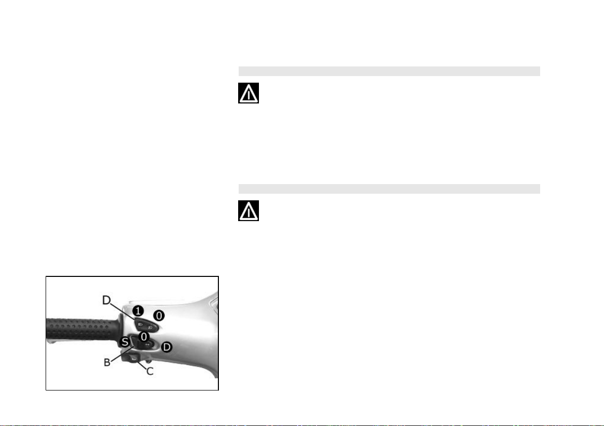
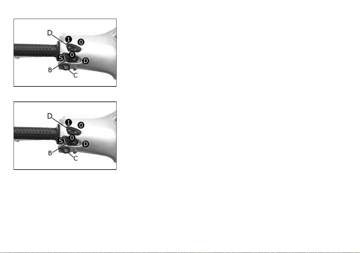
Switch direction indicators (01_05)
Lever towards "S" = Left turn indicator is switched on;
Lever towards "D" = Right turn indicator is switched on;
The lever returns automatically to position "0" and the turn indicator "B" remains on;
press the lever to turn them off.
01_05
10
1 Vehicle
Horn button (01_06)
Push the «C» button to sound the horn.
01_06
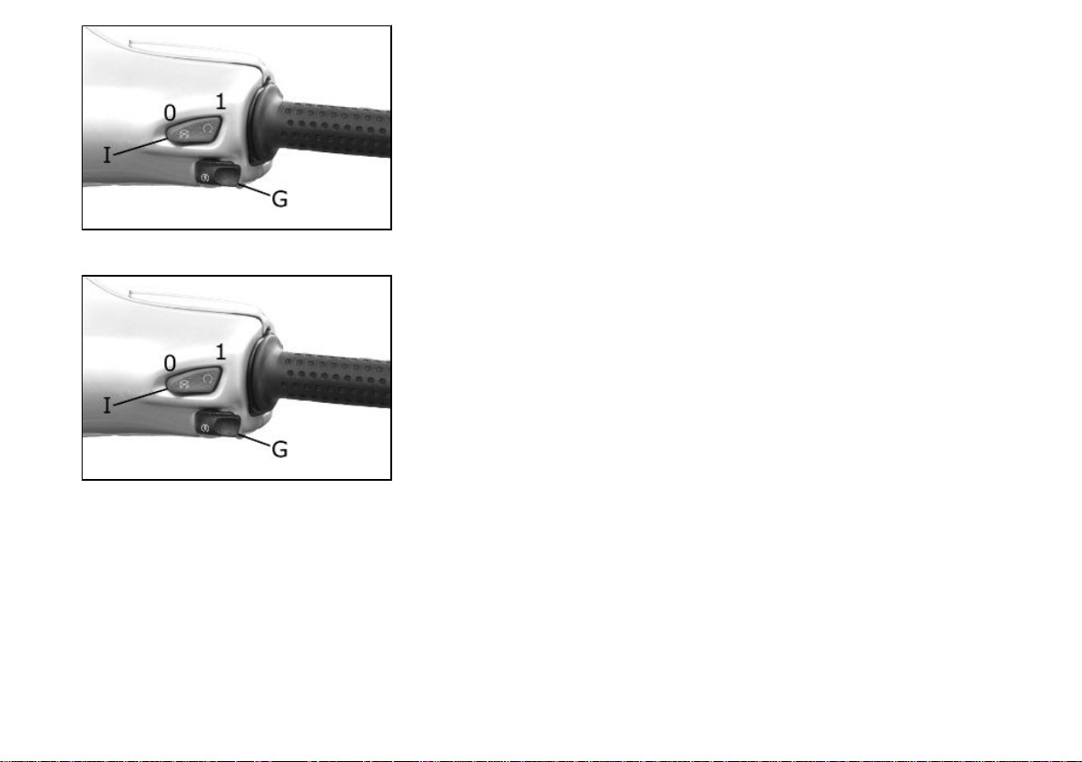
Light switch (01_07)
0 = Low-beam and tail light
1 = High-beam and tail light
01_07
11
01_08
01_09
Start-up button (01_08)
Starter button "G"
Engine stop button (01_09)
0 = OFF
1 = RUN
The immobilizer system
In order to enhance theft protection, the vehicle is equipped with a «PIAGGIO IMMOBILIZER » electronic engine locking device that is activated automatically when the
starter key is removed. Upon start-up, the «PIAGGIO IMMOBILIZER» system checks
the starter key, and only if this key is recognised will the immobilizer system allow the
vehicle to be started.
12
1 Vehicle
01_10
01_11
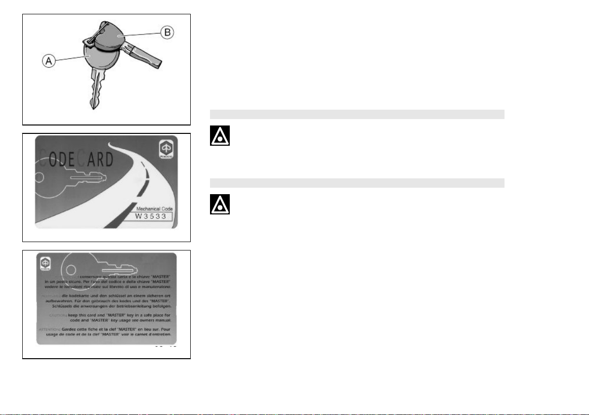
Keys (01_10, 01_11, 01_12)
The vehicle is supplied with two types of keys. The red-handgrip key «A» is the
"MASTER" key. Only a single copy of this key is supplied, which is necessary to program all your other keys and for your dealer to perform some maintenance operations.
We therefore recommend that it be used only under exceptional circumstances. The
black key «B» (single copy supplied) is used for normal operations and for start-up.
Together with the keys comes a CODE CARD which is imprinted with the mechanical
code of the keys.
WARNING
LOSING THE RED KEY PREVENTS ANY REPAIRS OF THE "PIAGGIO IMMOBILIZER" SYSTEM AND THE ENGINE CONTROL UNIT.
WARNING
KEEP THE "CODE CARD" AND THE RED HANDGRIP KEY IN A SAFE PLACE
(NOT ON YOUR VEHICLE).
01_12
13
01_13
Immobilizerdevice enabled indicator led (01_13)
Activation of the «PIAGGIO IMMOBILIZER» system is signalled by a flashing warning
light «N» (see «Analogue instrument panel» section).
In order to reduce battery discharge, the indicator LED turns off automatically after 48
hours of uninterrupted functioning.
Should the system fail, different LED flashing patterns will be provided by an Author-
ised Piaggio-Gilera Service Centre with information on the type of fault detected.
Operation
Every time the starter key is removed in the "OFF" or "LOCK" position, the safety
system activates the immobilizer system. Turning the key to "ON" disables the engine
lock, provided that the safety system recognises the code transmitted by the key. If
the code is not recognised, turn the key first to "OFF" and then to "ON"; if the lock
cannot be disabled, try with the other key supplied (red-coloured). If the engine cannot
be started, contact an Authorised Piaggio Service Centre, which is provided with
the electronic equipment required to detect and repair the system. The immobiliser is
also activated in the engine is switched off with the RUN OFF switch. This happens
even if the starter key is in position "ON".
When additional keys are required, please note that data storage (up to 3 keys max.)
must be done on all keys, both new ones and existing ones. Take the key with the red
grip and all the black keys supplied to an Authorised Piaggio Service Centre. The
codes of keys not submitted for the new storage procedure are deleted from the
memory. Any lost keys will therefore not be enabled to start the engine.
WARNING
EACH KEY HAS ITS OWN AND UNIQUE CODE, WHICH MUST BE STORED IN
THE SYSTEM CONTROL UNIT MEMORY.
14

1 Vehicle
VIOLENT SHOCKS MAY AFFECT THE ELECTRONIC COMPONENTS OF THE
KEY.
IF OWNERSHIP OF THE VEHICLE IS TRANSFERRED, THE RED HANDGRIP KEY
(AS WELL AS THE OTHER KEYS) AND THE "CODE CARD" MUST ALSO BE
TRANSFERRED TO THE NEW OWNER.
Programming the immobilizer system
Below is described the procedure to follow for programming the PIAGGIO IMMOBILIZER system and/or for storing other key codes. The programming procedure should
be carried out with the engine stop switch set to «RUN».
Procedure start - red key
Insert the red handgrip key in the switch key (in "OFF" position) and turn it to "ON".
After 1 - 3 seconds, turn the key to «OFF » again and pull it out.
Intermediate step - black key
After pulling out the red key, insert the black key within 10 seconds and promptly turn
it to "ON". After 1-3 seconds, turn the key to "OFF" again and pull it out. In this way,
a maximum of 3 black keys can be programmed by repeating the above procedure
keeping the indicated times.
Final step - red key
After pulling out the last black key, insert the red key again and turn it to "ON" (this
operation should be performed within 10 seconds of pulling out the previous key).
Leave it in this position for 1 to 3 seconds and return it to «OFF».
15
01_14
Proper programming check
Insert the red key disabling the transponder (i.e., tilt the key cap by 90°) and turn the
key to "ON". Perform the engine start-up operation. Ensure that the engine does not
start. Insert the black key and repeat the start-up operation. Check that engine starts.
WARNING
SHOULD THE ENGINE START WITH THE RED KEY (WITH TRANSPONDER OFF),
OR IN THE EVENT OF WRONG OPERATION DURING PROGRAMMING, REPEAT
THE PROCEDURE FROM THE BEGINNING.
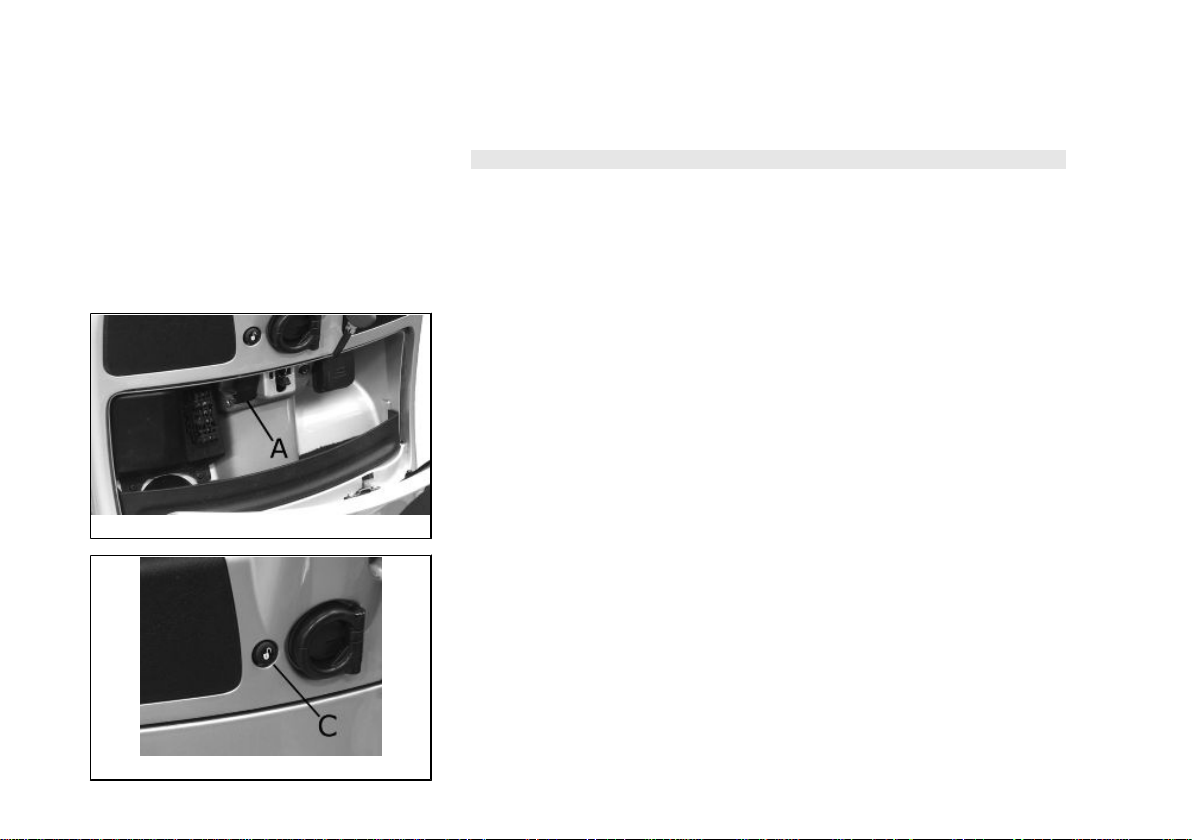
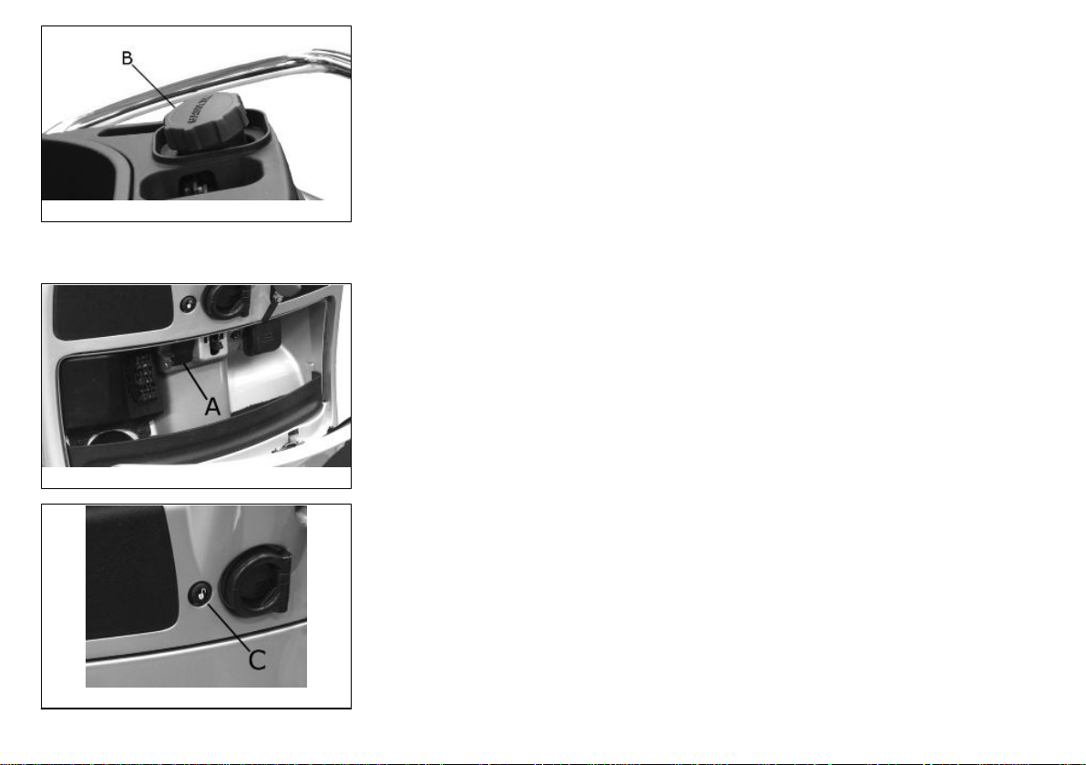
Accessing the fuel tank (01_14, 01_15, 01_16)
With the key set to «OFF» or «ON», or with engine on, it is possible to electrically open
the saddle by pressing the button «C». If the saddle opening system does not work,
operate the emergency lever «A». Then, unscrew cap «B» and the fuel tank can be
reached.
01_15
16
1 Vehicle
01_16
Opening the saddle (01_17, 01_18)
With the key set to «OFF» or «ON», or with engine on, it is possible to electrically open
the saddle by pressing button «C». If the electric opening does not work, use the
emergency lever "A". When the key is set to «LOCK» the saddle cannot be opened.
01_17
01_18
17
01_19
01_20
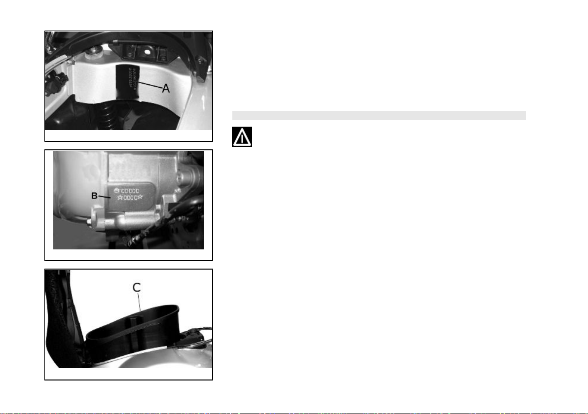
Identification (01_19, 01_20, 01_21)
The identification registration numbers consist of a prefix followed by a number stamped on both the chassis «A» and the engine «B». These numbers must always be
indicated on spare parts requests. To read the chassis number, lift the saddle and
remove the helmet compartment «C». We recommend checking that the chassis registration number stamped on the vehicle corresponds with that on the vehicle documentation.
CAUTION
BE REMINDED THAT ALTERING IDENTIFICATION REGISTRATION NUMBERS
CAN LEAD TO SERIOUS PENAL SANCTIONS (IMPOUNDING OF THE VEHICLE,
ETC.).
01_21
18
1 Vehicle
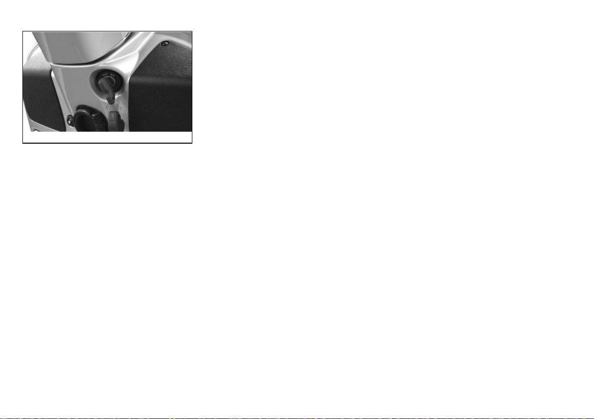
Rear top box opening (01_22)
Insert the key into the switch and press down until the glove compartment opens. If
the switch is set to "LOCK", turn the key to "OFF" or "ON" before pressing it down.
01_22
19

20

Vespa GTS 125
Chap. 02
Use
21

Checks
Before using the vehicle, check:
1. That there is enough fuel in the fuel tank.
2. That the fluid level for front and rear brakes is correct.
3. That tyres are properly inflated.
4. The correct functioning of tail lights, headlamp, turn indicators, stop light and license
plate light.
5. The correct functioning of front and rear brakes.
6. The oil level in the gearcase.
7. Engine oil level.
8. The coolant level.
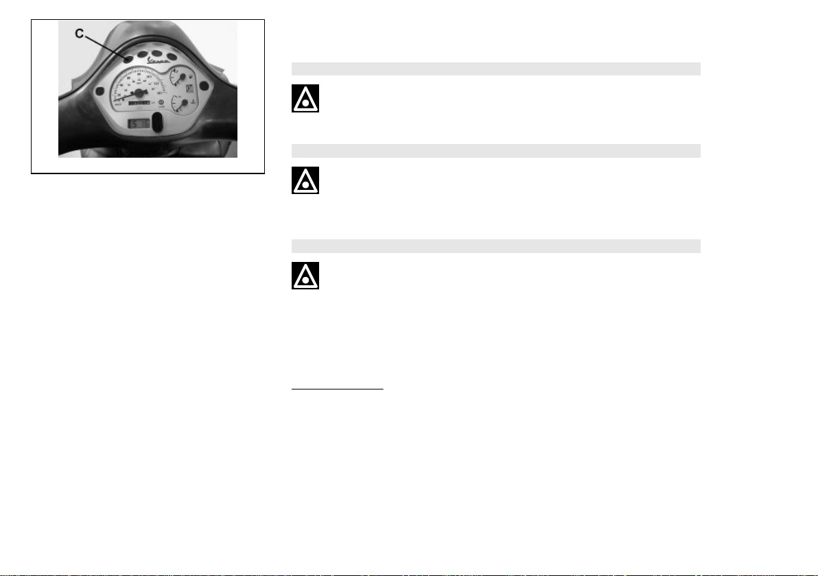
Refuelling (02_01, 02_02)
Fuel: lift up the saddle and unscrew the cap «B». Prescribed fuel: Minimum 95 octane
unleaded petrol. The warning light «C»indicates when the petrol tank reserve has
been reached.
WARNING
02_01
SWITCH OFF THE ENGINE BEFORE REFUELLING WITH PETROL.
PETROL IS HIGHLY INFLAMMABLE.
DO NOT SMOKE AND KEEP NAKED FLAMES AT A DISTANCE:FIRE HAZARD.
DO NOT INHALE FUEL FUMES.
22
2 Use
DO NOT ALLOW PETROL TO COME INTO CONTACT WITH HOT ENGINE OR
ANY PLASTIC PARTS.
CAUTION
PETROL DAMAGES THE PLASTIC PARTS OF THE BODYWORK.
CAUTION
02_02
USING OILS OTHER THAN THOSE RECOMMENDED CAN SHORTEN THE LIFE
OF THE ENGINE.
CAUTION
DO NOT USE THE VEHICLE TO THE COMPLETE EXHAUSTION OF THE FUEL;
SHOULD THIS OCCUR, DO NOT ATTEMPT TO START THE ENGINE. TURN THE
KEY SWITCH TO «OFF» AND TOP-UP THE TANK AS SOON AS POSSIBLE.
FAILURE TO FOLLOW THESE GUIDELINES COULD DAMAGE THE FUEL PUMP
AND/OR THE CATALYTIC CONVERTER.
Characteristic
Fuel tank capacity
About 10 l
23
02_03
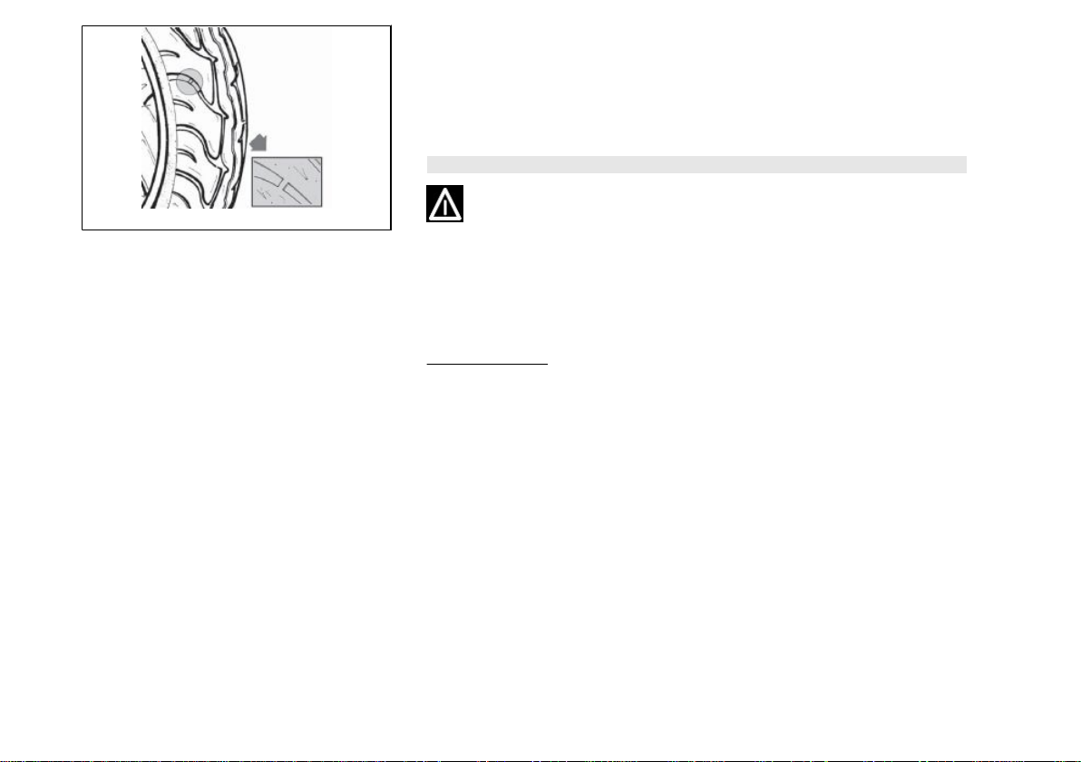
Tyre pressure (02_03)
Check the tyre pressure and wear periodically (roughly every 500 km). The tyres are
equipped with wear indicators; the tyres should be replaced as soon as these indicators become visible on the tyre tread. Also check that tyres do not show cuts on the
sides or irregular tread wear; if this occurs, go to an authorised workshop or at least
a workshop equipped to perform the replacement.
CAUTION
TYRE PRESSURE SHOULD BE CHECKED WHEN TYRES ARE COLD.INCORRECT TYRE PRESSURE CAUSES ABNORMAL TYRE WEAR AND MAKES RIDING DANGEROUS.
TYRES MUST BE REPLACED WHEN THE TREAD REACHES THE WEAR LIMITS
SET FORTH BY LAW.
Characteristic
Front tyre pressure
1.8 bar
Rear tyre pressure
2 bar
Rear tyre pressure - driver and passenger
2.2 bar
24
2 Use
02_04
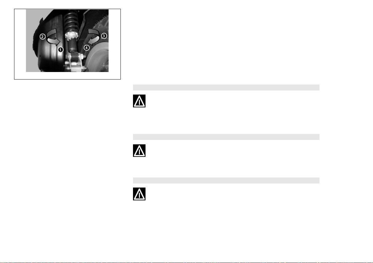
Shock absorbers adjustment (02_04)
The preloading of the springs can be adjusted to 4 positions acting on the ring nut
located in the lower part of the shock absorbers with the specific spanner supplied.
Position 1: minimum preload: driver only
Position 2 medium preloading: rider only
Position 3 medium preloading: rider and passenger
Position 4: maximum preloading: rider, passenger, and luggage.
In order to carry out this operation you will need to use the specific spanner in the kit.
CAUTION
RIDING THE VEHICLE WITH THE SPRING PRELOADING NOT CORRECTLY SET
FOR THE RIDER AND POSSIBLE PASSENGER, COULD REDUCE THE COMFORT OF THE RIDE AND THE PRECISION OF THE STEERING.
WARNING
WE RECOMMEND WEARING GLOVES WHILE CARRYING OUT THIS OPERATION IN ORDER TO AVOID INJURIES.
WARNING
WE STRONGLY RECOMMEND NOT TO ADJUST BOTH SHOCK ABSORBERS
WITH DIFFERENT PRELOADING
25

02_05
02_06
Running in (02_05)
WARNING
DURING THE FIRST 1000 KM DO NOT RIDE THE VEHICLE OVER 80% OF ITS
MAXIMUM SPEED. AVOID TWISTING THE THROTTLE GRIP FULLY OR KEEPING A CONSTANT SPEED ALONG LONG SECTIONS OF ROAD. AFTER THE
FIRST 1000 KM, GRADUALLY INCREASE SPEED UNTIL REACHING THE MAXIMUM PERFORMANCE.
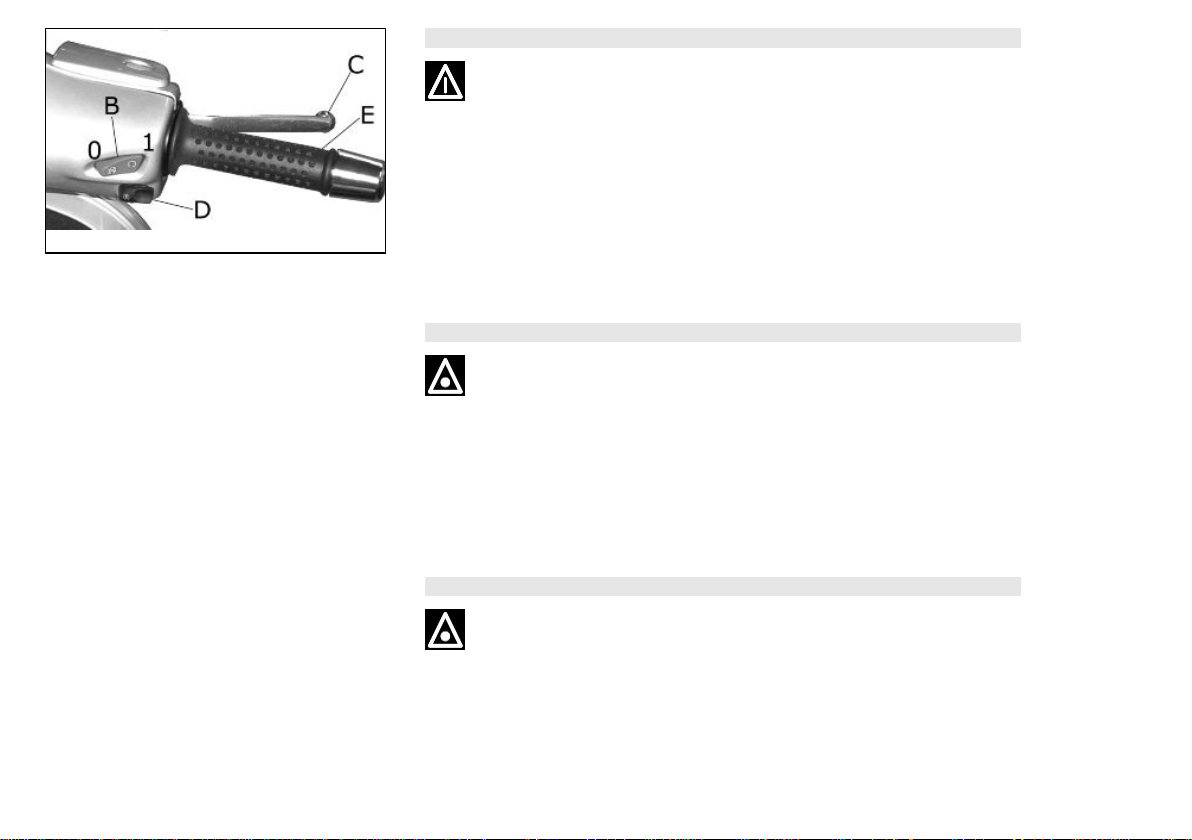
Starting up the engine (02_06, 02_07)
To start the engine it is necessary, before pressing the starter button, to pull and keep
pulled the front or rear brake lever, which activates the appropriate switch allowing
start-up.
1. Rest the vehicle on its centre-stand, ensuring the rear wheel is not touching the
ground.
2. Maintain the throttle grip «E» completely untwisted.
3. insert key into ignition switch «A» and turn it to "ON".
4. Make sure that the «B» "OFF-ON" switch is set to ON.
5. Pull lever «C» of the front or rear brake and then activate the starter button «D».
WARNING
THE AUTOMATIC TRANSMISSION MAKES THE REAR WHEEL TURN EVEN
WHEN THE THROTTLE IS SLIGHTLY TWISTED. RELEASE THE BRAKE CAREFULLY AFTER STARTING, AND THEN ACCELERATE GRADUALLY.
26
2 Use
CAUTION
DO NOT START-UP THE ENGINE IN CLOSED AREAS BECAUSE EXHAUST
GASES ARE TOXIC.
02_07
Precautions
WARNING
NEVER STRESS THE ENGINE AT LOW TEMPERATURES IN ORDER TO AVOID
POSSIBLE DAMAGE. BE CAREFUL NEVER TO EXCEED THE MAXIMUM SPEED
WHILE RUNNING DOWNHILL, IN ORDER TO AVOID DAMAGING THE ENGINE.
IN ANY CASE, IN ORDER TO PRESERVE THE ENGINE FROM PROLONGED
OVERREVVING, THE REVOLUTION LIMITER WILL BE ACTIVATED IF THE ENGINE SPEED EXCEEDS THE ESTABLISHED THRESHOLD. DO NOT ACTIVATE
THE REVOLUTION LIMITER RECURRENTLY SO AS TO AVOID DAMAGING THE
CATALYTIC CONVERTER.
WARNING
AFTER A LONG DISTANCE COVERED AT THE MAXIMUM SPEED, DO NOT STOP
THE ENGINE IMMEDIATELY, BUT LET IT RUN AT IDLE FOR A FEW SECONDS.
27
 Loading...