


SERVICE STATION
MANUAL
• X9 500 cc
Piaggio & C. S.p.A.
Pontedera
After Sales Service
Dis. 594523 - 04/01
Grafica e Stampa: C.L.D. - Pontedera (PI)
“© Copyright 2001 - PIAGGIO & C. S.p.A. Pontedera.
All rights reserved. Reproduction, in whole or in part, forbidden.”
Data subject to change without notice.
No responsibility is assumed for the use of non-genuine components and accessories other than those tested and approved by the Manufacturer.

SERVICE STATION
MANUAL
X9 500 cc
This manual has been designed by Piaggio for use in authorized dealers' and subdealers' workshops.
It is assumed that those who use this publication for maintaining and repairing Piaggio vehicles are familiar with the principles of mechanics and with vehicle repairing procedures and techniques. Any significant changes to the characteristics of the vehicles or to specific repairing procedures will be covered in updates of this manual.
Since satisfactory results cannot be obtained without the necessary equipment and tooling, we recommend referring to the pages of this manual concerning the specific equipment required and to the catalogue of specific tools.
Pieces of particularly important information are identified as follows:
Note: Provides important information intended to simplify and clarify a procedure.
Warning |
- Denotes specific procedures to be used to avoid damaging the vehicle. |
|
|
|
|
Caution |
|
- Identifies specific procedures to be followed to avoid injury to repairing personnel. |
|
|
|
NOTE - For any intervention to the engine, refer to the “Service Station Manual” for 500 cc Engines.

TABLE OF CONTENTS
VEHICLE SPECIFICATIONS AND OVERHAUL DATA
SPECIFIC TOOLING
1
2
MAINTENANCE AND TROUBLESHOOTING |
3 |
|
|
ELECTRICAL EQUIPMENT |
4 |
|
ENGINE |
5 |
|
FRONT AND REAR SUSPENSIONS |
6 |
|
BRAKING SYSTEM |
7 |
|
|
|
|
BODYWORK |
8 |
|
PREDELIVERY OPERATIONS |
9 |
|
TABLE OF WORKING TIMES |
10 |
|

Vehicle overhaul data
Assembly plays
1 |
|
|
|
|
|
|
|
(Values in mm) |
||
|
|
|
|
|
|
|
|
|
|
|
|
|
|
|
DIAMETER |
|
A |
|
43.2 |
|
|
|
|
|
MEASURING |
|
|
|
|
|
|
|
|
|
|
B |
|
43 |
|
|
|
|
|
|
HEIGHT |
|
|
||
|
|
|
|
|
|
|
|
|
|
|
|
|
|
|
|
|
|
|
|
|
|
|
|
|
|
|
|
01_004 |
|
Mating between piston and cylinder |
|
|
|
|
|
|
|
|
|
|
|
|
|
|
|
|
(Values in mm) |
||
|
|
|
|
|
|
|
|
|
|
PART |
DIMENSIONS |
|
MATING CLASSES |
|
ASSEMBLY |
||||
|
|
|
|
|
|
|
|
|
|
|
|
CODE |
CYLINDER |
|
PISTON |
|
CLEARANCE |
||
|
|
|
|
|
|
|
|
|
|
Cylinder |
92 - 0.010 |
A |
91.990 - 91.997 |
91.947 - 91.954 |
|
|
0.036 |
||
|
+ 0.018 |
|
|
|
|
|
|
||
Ø C |
|
B |
91.997 - 92.004 |
91.954 - 91.961 |
|
|
|||
|
|
|
- |
||||||
|
|
|
|
|
|
|
|
||
Piston |
91.961 + 0.014 |
C |
92.004 - 92.011 |
91.961 - 91.968 |
|
|
|||
|
|
0.050 |
|||||||
|
- 0.014 |
|
|
|
|
|
|
||
Ø P |
|
D |
92.011 - 92.018 |
91.968 - 91.975 |
|
|
|
|
|
|
|
|
|
|
|
|
|
|
|
The piston must be fitted so that the arrow faces the exhaust side. The piston rings must be fitted so that the marks face upwards.
Piston rings
Ring opening
|
Arrange for the |
|
piston rings |
|
opening as shown |
Assemble the rings |
in the figure |
“A” value of the ring |
|
2 and 3 with the |
inside the cylinder |
“Top” writing facing |
|
upwards. |
|
|
|
|
01_005 |
|
|
|
|
(Values in mm) |
|
|
|
|
|
PART |
DIMENSIONS |
CLEARANCE |
SEAT |
CLEARANCE |
|
|
CODE |
CLEARANCE |
AFTER USE |
1st Compression ring |
92 x 1.5 |
A |
0.15 - 0.35 |
0.5 |
2nd Compression ring |
92 x 1.25 |
A |
0.25 - 0.50 |
0.65 |
Scraper ring |
92 x 2.5 |
A |
0.25 - 0.50 |
0.65 |
|
|
|
|
|
1 - 7

Vehicle overhaul data
SHIMMING METHOD FOR LIMITING THE COMPRESSION RATIO: CR = 10.5 : 1
“A” MEASUREMENT (WITH PISTON AT TDC)
N.B.: The “A” measurement is referred to the piston projection or recess value; it indicates the type of gasket to be fitted on the cylinder to restore the compression ratio. Therefore the more the surface formed by the piston crown sticks out of the surface formed by the cylinder top, the thicker the gasket will be. Vice versa, the more the piston crown is hollow to
the cylinder top, the less thick the gasket will be.
+
-
FIT THE GASKETS SHOWN IN THE TABLE
ACCORDING TO THE “A” MEASUREMENT
01_006
NOTE: THE “A” MEASUREMENT MUST BE TAKEN WITH NO
GASKET FITTED BETWEEN CRANKCASE AND CYLINDER
“A” MEASUREMENT |
THICKNESS OF BASE GASKET |
|
|
- 0.185 - - 0.10 |
0.4 ± 0.05 |
|
|
- 0.10 - + 0.10 |
0.6 ± 0.05 |
|
|
+ 0.10 - + 0.185 |
0.8 ± 0.05 |
|
|
Crankshaft/crankcase axial clearance 0.1 - 0.5 mm (cold engine)
01_010
1 - 8

Vehicle overhaul data
Crankshaft/connecting rod axial clearance
1 |
01_007
PART |
DIMENSIONS |
CLEARANCE |
|
|
|
|
|
Web, transmission side |
A =0.8 ± 0.025 |
|
|
Shaft section, transmission side |
B =19.6 + 00.05 |
|
|
|
|
|
|
Connecting rod |
C =22 - 0.10 |
|
|
|
- 0.15 |
D = 0.20 - 0.40 |
|
Shaft section, flywheel side |
E =19.6 + 00.05 |
||
|
|||
Web, flywheel side |
F =13 ± 0.025 |
|
|
Crankshaft assembly |
G =63.5 + 0.1 |
|
|
|
- 0.05 |
|
|
|
|
|
Crankshaft alignment and diameters
- Measure the housings on both axes x and y.
|
Standard diameter |
|
|
Class 1 |
40.010 - 40.016 |
|
|
Class 2 |
40.016 - 40.022 |
|
|
01_008
Max. allowable runout: A = 0.15 mm
B = 0.01 mm
C = 0.010 mm
D = 0.10 mm
01_009
1 - 9

TABLE OF CONTENTS
SPECIFIC TOOLING |
2 |
|

Specific Tooling
Specific tools for Piaggio X9 500 cc 4-stroke 4-valve
RECOMMENDED TOOLS
TOOL NAME |
PART NO. |
Circlip pliers |
002465Y |
|
|
Steering thrust ring removing drift |
020004Y |
|
|
Crankshaft aligning tool |
020074Y |
|
|
Support for “METABO HG 1500/2” air heater |
020150Y |
|
|
“METABO HG 1500/2” air heater |
020151Y |
|
|
Mityvac-type vacuum pump |
020329Y |
|
|
Stroboscopic gun for twoand four-stroke engines |
020330Y |
|
|
Digital multimeter |
020331Y |
|
|
Single battery charger |
020333Y |
|
|
Multiple battery charger |
020334Y |
|
|
Magnetic stand and dial gauge |
020335Y |
|
|
Engine support connection |
020482Y |
Engine mount base |
020527Y |
|
|
Engine mount revolving base |
020604Y11 |
|
|

 = New tools
2 - 2

|
Specific Tooling |
|
NECESSARY TOOLS |
|
|
TOOL NAME |
PART NO. |
|
STEERING SEAT FITTING TOOL, to be fitted with parts 9 - Lower |
001330Y |
|
bearing adaptor, 10 - Upper bearing adaptor |
|
|
Bell Ø 80 mm |
001467Y002 |
|
20 mm pliers |
001467Y006 |
|
Bell Ø 63 mm |
001467Y007 |
2 |
18 mm pliers |
001467Y008 |
|
Bell Ø 45 mm |
001467Y017 |
|
Bell Ø 60 mm |
001467Y031 |
|
15 mm pliers |
001467Y034 |
|
Hub bearing extraction bell |
001467Y035 |
|
Steering tube ring spanner |
020055Y |
|
Oil pressure gauge |
020193Y |
|
Valve seal rings assembly tool |
020306Y |
|
37x40 mm adaptor |
020358Y |
|
42x47 mm adaptor |
020359Y |
|
52x55 mm adaptor |
020360Y |
|
20 mm guide (Driven pulley bearings) |
020363Y |
|
25 mm guide (Driven pulley bearings) |
020364Y |
|
Ø 28x30 mm adaptor |
020375Y |
|
Adapter sleeve |
020376Y |
|
Bushing (valve removing tool) |
020382Y012 |
|
15 mm guide |
020412Y |
|
Valve oil seal extractor |
020431Y |
|
Oil pressure gauge unio |
020434Y |
|
17 mm guide (countershaft bearings) |
020439Y |
|
Driven half pulley spring compressor |
020444Y |
|
46-55 mm spanner |
020444Y009 |
|
Ø 24 mm adaptor |
020456Y |
|
Steering tube lower bearing extractor |
020458Y |
|
Drift for fitting bearing on steering tube |
020459Y |
|
Injection tester kit |
020460Y |
|
Flywheel extractor |
020467Y |
|
Piston fitting band |
020468Y |
|
Injection tester reprogramming kit |
020469Y |
|
Piston pin retainer fitting tool |
020470Y |
|
Countershaft timing peg |
020471Y |
|
Flywheel retaining tool |
020472Y |
|
Clutch bell housing retaining tool |
020473Y |
|
Drive pulley stop spanner |
020474Y |
|
Piston position comparator support |
020475Y |
|
Pillar kit |
020476Y |
|
Ø 37 mm adaptor |
020477Y |
|
Driven pulley needle roller drift |
020478Y |
|
Countershaft stop spanner |
020479Y |
|
Fuel pressure measuring kit |
020480Y |
|
Control unit interface wiring harness |
020481Y |
|
30 mm guide |
020483Y |
|
Piston stop fork |
020512Y |
|
Compass wrench (valve lifter bell stop) |
020565Y |
|
Exhaust gas analyser |
494929 |
|
2 - 3
Spark plug
Check and replacement
Warning - Remove the spark plug when the engine is cold. Replace the spark plug every 12,000 km. The use of unsuitable ignition control units and spark plugs other than those specified can seriously damage the engine.
Recommended spark plug: CHAMPION RG 6 YC NGK CR 7 EKB
-Put the vehicle on the central stand.
-Open the door on the left side of the vehicle by levering in the recess in the lower part of the door after removing the screw.
-Disconnect the spark plug HV cable cap.
-Unscrew the spark plug with the spanner provided.
-Check the spark plug to see if the insulator is cracked, the electrodes are worn out or excessively sooty. Also check the condition of the seal washer and measure the spark gap with a suitable thickness gauge.
Spark gap: 0,7 - 0,8 mm
-If necessary adjust the spark gap by carefully bending the side electrode.
If the spark plug has any of the defects mentioned above, replace it with a plug of the recommended type.
-Insert the plug into the hole with the proper inclination, screw it in fully by hand and then tighten it with the specially designed spanner.
Tightening torque: 10 N·m (1 Kg·m)
-Push the spark plug cap all the way down onto the spark plug and then proceed to the reassembly.
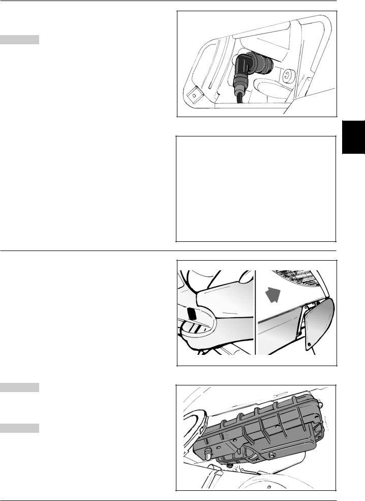
Air filter
-Remove the left-hand lower side panel as described in Chapter 8-Bodywork.
-Remove the cleaner cap after loosening the eight fixing screws, including one screw of the knob type.
-Pull out the filter element.
-Replace the air filter with a new one.
Note: Check and if necessary blow the air filter every 6,000 km. Direct the air jet from the inside to the outside of the filter (i.e. in the opposite direction to the air flow during normal engine operation).
Warning - If the vehicle is mostly used on dusty
roads, the air filter needs to be cleaned and replaced at shorter intervals than indicated in the Maintenance Schedule.
Warning - Do not run the engine if the air filter is not
in place as this would result in excessive wear of the cylinder and piston as well as in damage to the throttle body.
Maintenance
03_001
3
03_002
03_003
03_004
3 - 3
Maintenance
Engine oil level
In four-stroke engines oil is used to lubricate the valve gear components, the crankshaft bearings and the power plant. A lack of engine oil can cause serious damage to the engine.
In all four-stroke engines, oil deterioration and consumption are, to some extent, normal, especially during running-in. Consumption partly depends on the riding style (for example, constantly riding at full throttle increases oil consumption).
Checking the oil level
Perform this operation when the engine cold, as described below:
1)Put the vehicle on its central stand on a flat surface.
2)Unscrew dipstick «A», dry it with a clean cloth and refit by screwing it completely.
3)Remove the dipstick again and check that the oil level is between the MAX and MIN marks on the
dipstick; top up if necessary.
The MAX level mark indicates an amount of about 1700 cc of engine oil.
The level will be lower if checked after using the vehicle (i.e. when the engine is hot). To obtain a correct indication of the oil level, wait for at least 10 minutes after switching off the engine.
Topping up
If the oil level is too low, top up by adding fresh oil without exceeding the MAX level.
Approximately 400 cc of oil are needed to restore the level between the MIN and MAX marks.
Oil pressure warning light
A warning light on the instrument panel comes on when the ignition key is turned to the “ON” position. The light must go out after the engine has started.
Should the warning light come on while braking, idling or cornering, check the oil level and the lubrication system as soon as possible.
Renewing the oil and the filter
The oil and the filter must be renewed every 6,000 km. Drain all the oil from the engine by removing gauze strainer drain plug «B» on the transmission side. To facilitate the outflow, also remove cap/dipstick «A». Once the oil has drained completely through the drain hole, unscrew oil filter cartridge «C» and remove it as described below.
Since a certain amount of oil remains in the circuit, the replenishment must be made by adding approximately 1,500 cc of fresh oil through cap «A». Subsequently start the engine, let it idle for a few minutes and then switch it off. After about 5 minutes, check the level and if necessary top up without exceeding the MAX level. The filter cartridge must be replaced every time the oil is changed. For top-ups and renewals use fresh oil of the Selenia HI Scooter 4 Tech type.
Note: Renew the oil when the engine is hot.
MAX MIN
03_005
A
C
03_006
B
03_007
3 - 4

Maintenance
Replacing the filter
Warning - Do not dispose of the oil in the environ-
ment. Carry out the disposal of the oil, the gasket and the filter in accordance with the law.
Caution - To avoid burns, take care not to touch hot engine parts.
-Remove the silencer.
-Remove filler plug «A».
-Remove and clean the drain plug gauze strainer with compressed air.
-Using a strap wrench for filters, remove cartridge filter «C».
-Ensure that the O-rings on the prefilter and the drain plug are in good condition.
-Lubricate the O-rings and then refit the gauze strainer and the oil drain plug. Tighten the drain plug with the prescribed torque.
-Fit a new cartridge filter after lubricating the O-ring. Turn in until the gasket makes contact and then tighten it with the prescribed torque.
-Reinstall the silencer.
-Add engine oil as previously described.
Tightening torque:
Tappo scarico olio motore Engine oil drain plug: 24 - 30 N·m
Oil filter: 12 - 16 N·m
Oil type: Selenia HI Scooter 4 Tech
Checking the hub oil level
-Put the vehicle on the central stand on level ground.
-Unscrew oil dipstick «A», wipe it with a clean cloth, reinsert it and then screw it in fully.
-Pull out the dipstick again and check that the oil level is between the MIN and MAX marks (see figure); if the level is below the MIN mark, top up with oil.
-Reinsert the dipstick and screw it tight.
A
3 |
MAX
MIN
03_008
Renewing the hub oil
-Remove oil filler plug «A».
-Unscrew oil drain plug «B» and drain all the oil.
-Retighten the oil drain plug and then fill the hub with fresh oil.
Recommended oil: TUTELA ZC 90
Hub oil capacity: ~ 250 cc
03_009
3 - 5

Maintenance
Engine cooling
Adding coolant and bleeding air from the system
The level of the fluid must be checked every 6,000 km when the engine is cold.
Follow these steps:
-Put the vehicle on the central stand on level ground.
-Remove the expansion tank cap and top up if the coolant is below or near the MIN level in the expansion tank. The level of the fluid should always be between the MIN and MAX marks.
-To have an indication of the coolant level, refer to the groove in the plastic strip that can be seen through the coolant filler hole. The upper and lower parts of the groove correspond to the MAX and MIN levels respectively.
-The coolant consists of a 50 percent mixture of demineralized water and antifreeze solution with a base of ethylene glycol and corrosion inhibitors.
Total coolant capacity: ~ 1,8 lt
-To check the presence of air in the circuit follow the procedure described in Chapter 11-Cooling, in the manual of Engine 500 cc.
-Switch off the engine and allow it to cool down. After a few minutes, remove the expansion tank cap and check the level of the fluid.
-If necessary, top up by pouring fresh coolant into the expansion tank up to the correct level.
Warning - To prevent the coolant from leaking out of the expansion tank during use, be sure to never exceed the MAX level when refilling.
Water pump
03_010
03_011
If the water pump becomes noisy or liquid leaks through the pump drain hole, check the water pump as described in Chapter 5-Flywheel cover of the manuale Engine 500 cc. Perform the following preliminary operations:
-Put the vehicle on the central stand on level ground.
-Remove the lower right-hand side panel and the right-hand footboard as described in Chapter 8- Bodywork.
-Remove the silencer to gain access to the flywheel cover as described in Chapter 5-Engine;
-Remove the sleeves from the water pump cover and the filler cap from the expansion tank and empty the cooling circuit.
-As described in the manual Engine 500cc, partially drain the system and overhaul the pump.
-After solving the problem and refitting all components, fill and bleed the cooling circuit again.
N.B.: Change the coolant as described in Chapter 11Cooling of the Manual Engine 500 cc
Warning - Perform the operation when the engine
is cold.
-Remove the water pump cover shown in the figure after loosening the six fixing screws.
-Cooling circuit capacity: ~ 1,8 lt.
03_013
3 - 6

Maintenance
Adjusting the play of the valves - Checking the valve gear timing
To adjust the play of the valves and to check the valve gear timing as described in Chapter 7-Thermal Unit and Timing system of the Engine manual, follow these preliminary steps:
-Put the vehicle on the central stand;
-Remove the relevant body sections to gain access to the pivot fixing the engine to the swingarm (refer to Chapter 8-Bodywork);
-Support the bottom of the engine, e.g. with a jack;
-Remove the engine from the frame as described in Chapter 5-Engine;
-Shift the engine backwards to make room for the removal of the cylinder head cover (until the swingarm cross member touches the starter motor).
-After adjusting the play of the valves, refit the components by following the reverse procedure to the removal.
Warning - Do not lower the engine too much to prevent it from touching the stop push button of the electrohydraulic stand.
Note: The checking areas are shown in the two figures at the right.
Play of valves:
Intake |
0.15 |
mm cold engine |
,20 |
||
Exhaust |
0,20.15 |
mm cold engine |
03_012
3 |
03_012_4
Checking the level
To gain access to the front and rear brake fluid reservoirs, remove the covers on the handlebar cover.
Follow these steps:
-Put the vehicle on the central stand and turn the handlebar to the central position.
-Remove cap «A» after loosening fixing screw «B».
-Check the level of the fluid through the sight.
A certain decrease in the level of the fluid occurs as a result of pad wear.
Restoring the brake fluid level
Warning - Only use brake fluid classified as DOT 4.
Brake fluid type: TUTELA TOP 4 Use the following procedure:
Remove the «A», covers and the tank cap by unscrewing the two screws, remove the gasket and restore the brake fluid level with liquid of the recommended type, without exceeding the max. level.
B
A 
03_012_1
03_012_2
3 - 7
Maintenance
Warning - Keep the brake fluid away from the skin, the eyes and clothing. In case of contact, rinse generously with water.
Warning - The brake fluid is highly corrosive. Take care not to spill it on the paintwork.
Warning - The brake fluid is hygroscopic, i.e. it absorbs humidity from the air. If the humidity contained in the fluid exceeds a given concentration, the braking action becomes insufficient.
Never draw the fluid from open or partly empty containers.
Under normal climatic conditions the fluid should be renewed every 20,000 km, or in any case every two years.
N.B.: Change the brake fluid and bleed the system as described in Chapter 7-Braking system.
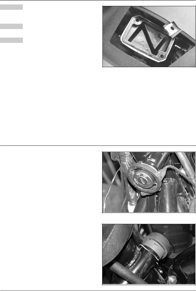
Steering lock
Disassembly with lock turned to “OFF”
-Remove the rear shield as described in Chapter 8- Bodywork.
-Remove the immobilizer aerial shown in the figure.
-Disconnect the wiring.
-Pull out the retaining spring shown in the figure and remove the ignition switch.
03_012_3
03_014
03_015
3 - 8

Maintenance
-Push the bolt lightly and extract the retainer from the milled part shown in the figure.
-Extract the bolt assembly from the lock body.
-To refit, follow the reverse procedure.
Removal with lock in LOCK position
The bolt retaining spring is not accessible in the LOCK position. It is then necessary to drill the bolt as show in the figure to eject it.
Note: To refit the bolt from this position, first disengage the steering lock by putting the lock body (inner and outer part) in the OFF position.
Proceed as described in the previous paragraph.
03_016
3 |
|
|
|
03_017 |
Adjusting the headlight |
|
|
|
- |
Place the unloaded vehicle on a level surface, 10 |
|
|
|
metres from a half-lit white screen, with the tyres |
|
|
|
inflated to the prescribed pressure. Ensure that the |
|
|
|
axis of the vehicle is perpendicular to the screen. |
|
|
- Draw a horizontal line on the screen 70-73 cm above |
|
|
|
|
the ground. |
|
|
- Switch on the headlight, turn on the low beam and |
|
|
|
|
check that the horizontal line that divides the dark |
10 |
m |
|
area from the lighted area is not above the line |
||
|
|
||
|
previously drawn on the screen. To shift the head- |
|
|
|
light, use the specially designed screw in the front |
|
|
|
shield (see figure). |
|
03_018 |
|
|
|
|
3 - 9

TABLE OF CONTENTS
ELECTRICAL EQUIPMENT |
4 |
|
ELECTRICAL EQUIPMENT
|
|
|
|
|
|
46 |
|
|
|
|
38 |
43 |
|
28 |
|
|
|
|
|
26 |
25 |
||
|
|
|
|
|
|
||
|
|
|
|
|
|
29 |
22 |
|
16 |
8 |
42 |
|
|
27 |
|
17 |
|
|
|
||||
32 |
|
|
|
|
|||
20 |
|
|
|
|
|
|
|
|
|
|
|
|
|
6 |
|
33 |
|
|
|
|
|
|
|
|
|
|
|
|
|
|
|
35 |
|
|
19 |
37 |
44 |
|
47 |
|
|
41 |
|
|
|||
15 |
|
|
|
21 |
|
18 |
|
|
|
|
2 |
|
|
||
|
|
|
|
49 |
|
|
|
|
|
|
3 |
|
|
|
|
|
|
|
|
|
|
|
|
|
|
|
4 |
|
|
|
23 |
|
|
|
|
5 |
7 |
|
|
48 |
|
|
|
|
30 |
||
|
|
|
|
|
|
||
36 |
|
|
|
|
45 |
|
52 |
|
|
|
|
|
|
|
|
34 |
|
|
|
14 |
|
24 |
|
|
|
|
|
|
|
||
|
|
|
|
|
|
|
40 |
|
|
|
|
|
12 |
|
39 |
|
|
|
|
|
|
|
|
9 |
13 |
10 |
51 |
|
|
11 |
1 |
||
|
|
|
|
|
|
|
|
50 |
31 |
1 |
SIDESTAND SWITCH |
27 |
TURN INDICATOR SWITCH |
2 |
VOLTAGE REGULATOR |
28 |
HORN BUTTON |
|
|
|
|
3 |
STAND CONTROL UNIT |
29 |
HAZARD WARNING LIGHT BUTTON |
|
|
|
|
4 |
ELECTRONIC CONTROL UNIT RELAY SWITCH |
30 |
RESET BUTTON |
|
|
|
|
5 |
ENGINE STOP RELAY SWITCH |
31 |
TRUMPET HORN |
|
|
|
|
6 |
SERVICES ELECTROMAGNETIC SWITCH |
32 |
LH REAR LIGHT WITH 5W PARKING LIGHT BULB AND 10W |
|
|
|
|
7 |
FUSE BOX (3 X 7.5A, 1 X 15A) |
|
TURN INDICATOR BULB |
|
|
|
|
8 |
NO. 2 SOLENOID STARTERS |
33 |
REAR BRAKE LIGHT, 5 X 2.3W BULB |
|
|
|
|
9 |
375W FLYWHEEL MAGNETO |
|
|
10 |
2 X STAND BUTTON |
34 |
NUMBER-PLATE LIGHT 12V-5W |
|
|
|
|
11 |
STAND PUMP MOTOR |
35 |
RH REAR LIGHT WITH 5W PARKING LIGHT BULB AND 10W |
|
|
|
|
12 |
PUMP ASSEMBLY WITH LEVEL INDICATOR |
|
TURN INDICATOR BULB |
|
|
|
|
13 |
STARTER MOTOR |
36 |
12V-14Ah BATTERY |
|
|
|
|
14 |
HELMET COMPARTMENT LAMP BUTTON |
37 |
FRONT BRAKE LIGHT BUTTON |
|
|
|
|
15 |
HELMET COMPARTMENT LAMP |
38 |
ENGINE STOP SWITCH |
|
|
|
|
16 |
12V SOCKET |
39 |
WHEEL REVOLUTION SENSOR |
|
|
|
|
17 |
2 X REAR FUSE BOX FOR CONTROL UNIT (1 X 3A, 1 X 5A, |
40 |
RH FRONT TURN INDICATOR, 10W BULB |
|
|
|
|
|
1 X 10A, 1 X 3A) |
41 |
MAIN RELAY SWITCH |
|
|
|
|
18 |
DIODE BOX (2 X 6 A AND 2 A DIODE) |
42 |
LIGHTS SELECTOR SWITCH |
|
|
|
|
19 |
FUSE BOX (2 X 7.5A, 1 X 15A AND 5A) |
43 |
START BUTTON |
|
|
|
|
20 |
FUSE BOX WITH STRIP FOR STAND PUMP |
44 |
STAND BUTTON |
|
|
|
|
|
ELECTROMAGNETIC SWITCH (NO. 1 OF 70A) |
45 |
IGNITION SWITCH |
|
|
|
|
21 |
DIGITAL INSTRUMENT SET (11 WARNING LIGHTS AND LEDS) |
46 |
RADIO DISPLAY |
|
|
|
|
22 |
ANALOG INSTRUMENT SET (5 LAMPS) |
47 |
ELECTRIC FAN RELAY SWITCH |
|
|
|
|
23 |
HEADLIGHT, 2 X PARKING LIGHT BULB, HIGH/LOW BEAM |
48 |
30A FUSE WITH SOLENOID STARTER |
|
|
|
|
|
55/55W BULB |
49 |
RADIO CONROL UNIT/INTERCOM/SPEAKERPHONE |
|
|
|
|
24 |
LH FRONT TURN INDICATOR WITH 10W BULB |
50 |
No. 2 PUMP ELECTROMAGNETIC SWITCHES |
|
|
|
|
25 |
REAR BRAKE LIGHT BUTTON |
51 |
RELAY SIGNALER GLUED |
|
|
|
|
26 |
LIGHTS SWITCH WITH HEADLIGHT FLASH |
52 |
No. 2 HEADLIGHT ELECTROMAGNETIC SWITCHES |
|
|
|
|
|
|
|
|
4 - 2

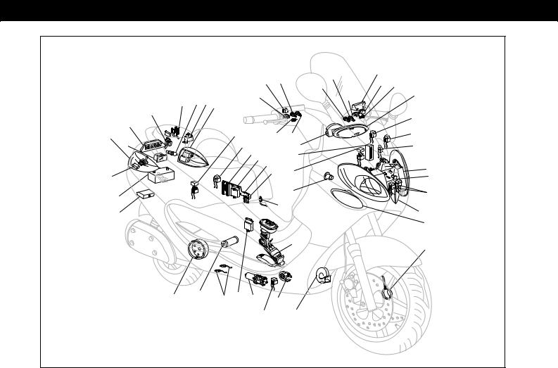
Electrical equipment diagram
Electrical equipment devices
1. Digital instrument panel (11 LED indicators).
2. Analog instrument panel (5 bulbs).
3. Headlight (2 parking light bulbs, 55/55W low/high beam bulbs).
4. LH front turn indicators (10W bulb).
5. Rear brake light button.
6. Lights selector switch with headlight flash.
7. Turn indicator switch.
8. Horn button.
9. Hazard warning light button.
10. Reset button.
11. Trumpet horn.
12. Sidestand switch.
13. Voltage regulator.
14. Stand control unit.
15. Engine stop relay switch.
16. Electronic control unit relay switch.
17. Stand pump relay switches.
18. LH rear light (5W parking light bulb, 10W turn indicator bulb).
19. Rear brake light (5 x 2.3W bulbs). 20. Number-plate light with bulb.
21. RH rear light (5W parking light bulb, 10W turn indicator bulb).
22. 12V-14Ah battery.
23. Fuse box (3 x 7.5A fuse, 1 x 15A fuse). 24. Starting relay switch.
25. Flywheel magneto (375W).
26. Engine oil pressure sensor.
27. Coolant temperature sensor.
28. Engine rpm sensor.
29. Air temperature sensor.
30. Idle speed adjusting motor.
31. Throttle potentiometer.
32. Petrol injector.
33. 2 stand switches.
34. Stand pump motor.
35. Injection electronic control unit.
36. Decoder.
37. Front brake light button.
38. Engine stop switch.
39. Wheel revolution sensor.
40. RH front turn indicator (10W bulb).
41. Relay switch.
42. Lights switch.
43. Start button.
44. Stand button.
45. Immobilizer aerial.
46. Ignition switch.
47. Electric fan.
48. Electric fan relay switch.
49. Main relay switch.
50. HV coil.
51. Fuel gauge with pump.
52. Starter motor.
53. Helmet compartment lamp button.
54. Helmet compartment lamp.
55. 12V socket.
56. 2 rear fuse boxes for control unit (1 x 3A fuse, 1 x 5A fuse, 1 x 10A fuse, 1 x 3A fuse).
57. Radio display.
58. Relay switch.
59. Outside temperature sensor.
60. Diode box (2 x 6A/2A diodes).
61. Fuse box (2 x 7.5A fuse, 1 x 15A fuse, 1 x 5A fuse). 62. Fuse box with base for stand pump (1 x 70A fuse).
63.Intercom/radio control unit.
64.Intercom connectors.
65.Relay signaler glued.
4 |
ELECTRICAL CABLES COLOUR: B=White - Bl=Blue
- G=Yellow - Mr=Brown - N=Black - BV=White-Green -
GN=Yellow-Black - Gr=Grey - Rs=Pink - R=Red -
Vi=Violet - V=Green - VN=Green-Black - BN=White-
Black - BBl=White-Blue - GV=Yellow-Green -
Ar=Orange - Az=Azure - GrBl=Grey-Blue - GrN=Grey-
Black.
Warning - When working on the electrical equipment, take special care to ensure that the leads that link up to the electronic control device are properly connected by observing the polarity and colour coding of the connectors.
4 - 5
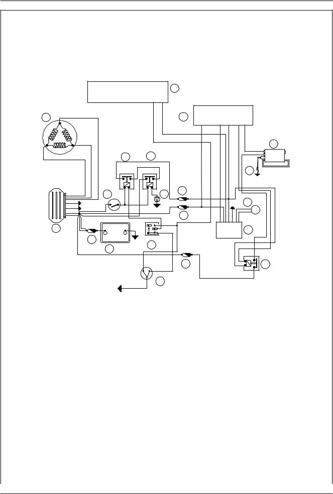
Schematic wiring diagrams
Ignition section
8
4 |
5 |
6
12 |
|
|
13 |
|
|
|
|
|
7 |
|
|
8 7 |
|
|
8 7 |
30 |
|
3 0 |
|
8 5 |
8 6 |
8 5 |
8 6 |
9 |
2 |
|
|
20 |
|
|
|
|
|
11 |
10
3 |
- |
|
|
1 |
+ |
|
|
|
|
15 |
|
OFF RUN |
|
|
|
16 |
|
|
|
14 |
|
|
|
|
|
|
|
8 |
|
|
|
|
8 |
7 |
|
|
|
5 |
|
|
DOWN |
UP |
17 |
18 |
|
8 |
|
||
|
|
|
6 |
3 |
|
|
|
|
0 |
|
|
19 |
|
|
04_002
1 |
IMMOBILIZER DECODER |
11 |
IMMOBILIZER AERIAL |
|
2 |
IGNITION SWITCH CONTACTS |
12 |
ENGINE STOP RELAY SWITCH |
|
3 |
VOLTAGE REGULATOR |
13 |
MAIN RELAY SWITCH |
|
4 |
FLYWHEEL MAGNETO |
14 |
12V-14Ah BATTERY |
|
|
|
|
|
|
5 |
INJECTION ELECTRONIC POWER UNIT |
15 |
30A FUSE |
|
6 |
HV COIL |
16 |
ENGINE STOP SWITCH |
|
|
|
|
|
|
7 |
SPARK PLUG |
17 |
10A FUSE |
|
|
|
|
|
|
8 |
DIGITAL INSTRUMENT SET |
18 |
ELECTRONIC POWER UNIT ELECTROMAGNETIC SWITCH |
|
|
|
|
|
|
9 |
5A FUSE |
19 |
SIDE STAND SWITCH |
|
|
|
|
|
|
10 |
3A FUSE |
20 |
2A DIODE |
|
|
|
|
|
|
4 - 6
Schematic wiring diagrams
Lights section
3 |
5 |
3 0 |
8 7 |
1 |
|
8 6 |
8 5 |
6 |
7 |
|
4 |
2 |
1 |
0 |
3 0 |
8 7 |
|
2 |
8 5 |
8 6 |
8
I 0 P
22
|
|
|
8 6 |
8 5 |
|
|
|
|
23 |
|
|
|
15 |
14 |
3 0 |
8 7 |
10 |
20 |
|
|
|||
21 |
|
12 |
9 |
|
|
|
13 |
|
|||
|
|
|
- +
19
16
- |
+ |
18 |
17 |
11 |
04_003
|
1 |
12V-55W LOW BEAM BULB |
12 |
7.5 A FUSE |
|
2 |
12V-55W HIGH BEAM BULB |
13 |
15 A FUSE |
|
|
3 |
LOW BEAM RELAY SWITCH |
14 |
7.5 A FUSE |
||
4 |
HIGH BEAM RELAY SWITCH |
15 |
7.5 A FUSE |
||
5 |
DIGITAL INSTRUMENT SET |
16 |
30 A FUSE |
||
6 |
LIGHTS SWITCH |
17 |
12V-14Ah BATTERY |
||
7 |
2 x 12V-5W FRONT PARKING LIGHT BULB, 2 x 12V-5W REAR |
18 |
HELMET COMPARTMENT LAMP BUTTON |
||
|
|
PARKING LIGHT BULB, 1 x 12V-5W NUMBER-PLATE LIGHT BULB |
19 |
12V-5W HELMET COMPARTMENT LAMP BULB |
|
8 |
IGNITION SWITCH CONTACTS |
20 |
12V-180W SOCKET |
||
9 |
MAIN RELAY SWITCH |
21 |
15A FUSE |
||
10 |
FLYWHEEL MAGNETO |
22 |
LIGHTS SELECTOR SWITCH |
||
11 |
VOLTAGE REGULATOR |
23 |
2A DIODE |
||
4 |
4 - 7
 Loading...