


MANUALE STAZIONE DI SERVIZIO
667270 - 667275 (IT-EN-FR-DE-ES-EL)
APE TM Benzina

MANUALE
STAZIONE DI
SERVIZIO
APE TM Benzina
© Copyright 2012 - PIAGGIO & C. S.p.A. Pontedera.
All rights reserved. No part of this publication may be reproduced. This publication has been edited by:
After sales - PIAGGIO & C. S.p.A.
V.le Rinaldo Piaggio, 23 - 56025 PONTEDERA (Pi)
ITALY www.piaggio.com

MANUALE STAZIONE DI
SERVIZIO
APE TM Benzina
WORKSHOP MANUAL
This workshop manual has been drawn up by PIAGGIO & C. Spa to be used by the workshops of Piaggio dealers. This manual is addressed to Piaggio service mechanics who are supposed to have a basic knowledge of mechanics principles and of vehicle fixing techniques and procedures. Any important changes made to the vehicles or to specific fixing operations will be promptly reported by updates to this manual. Nevertheless, no fixing work can be satisfactory if the necessary equipment and tools are unavailable. It is therefore advisable to read the sections of this manual relating to specific tools, along with the specific tool catalogue.
The descriptions and illustrations given in this publication are not binding. While the basic specifications as described and illustrated in this manual remain unchanged, PIAGGIO reserves the right, at any time and without being required to update this publication beforehand, to make any changes to components, parts or accessories, which it considers necessary to improve the product or which are required for manufacturing or construction reasons.
Not all versions/models shown in this publication are available in all countries. The availability of single versions should be checked at the official Piaggio sales network.
N.B. Provides key information to make the procedure easier to understand and carry out.
CAUTION Refers to specific procedures to carry out for preventing damages to the vehicle. Refers to specific procedures to carry out for preventing damages to the vehicle. Refers to specific procedures to carry out for preventing damages to the vehicle. Refers to specific procedures to carry out for preventing damages to the vehicle.
WARNING Refers to specific procedures to carry out to prevent injuries to the repairer.
Personal safety Failure to completely observe these instructions will result in serious risk of personal injury.
Safeguarding the environment Sections marked with this symbol indicate the correct use of the vehicle to prevent damaging the environment.

Vehicle intactness The incomplete or non-observance of these regulations leads to the risk of serious damage to the vehicle and sometimes even the invalidity of the guarantee.

INDEX OF TOPICS
GENERAL GUIDELINES |
GEN |
|
|
|
|
CHARACTERISTICS |
CH |
|
|
|
|
SPECIAL TOOLS |
ST |
|
|
|
|
MAINTENANCE |
MA |
|
|
|
|
EMISSION CONTROLO SYSTEM |
CO EM |
|
|
|
|
TROUBLESHOOTING |
TROUBL |
|
|
|
|
ELECTRICAL SYSTEM |
ES |
|
|
|
|
ENGINE FROM VEHICLE |
EV |
|
|
|
|
ENGINE |
EN |
|
|
|
|
GEAR-BOX |
GE |
|
|
|
|
DIFFERENTIAL |
DI |
|
|
|
|
BRAKING SYSTEM |
BS |
|
|
|
|
STEERING COLUMN |
SC |
|
|
|
|
SUSPENSIONS |
SS |
|
|
|
|
TIPPER VERSION |
VR |
|
|
|
|
CHASSIS |
CH |
|
|
|
|
PRE-DELIVERY |
PD |
|
|

INDEX OF TOPICS
GENERAL GUIDELINES |
GEN |
APE TM Benzina |
General guidelines |
|
|
Maintenance guidelines
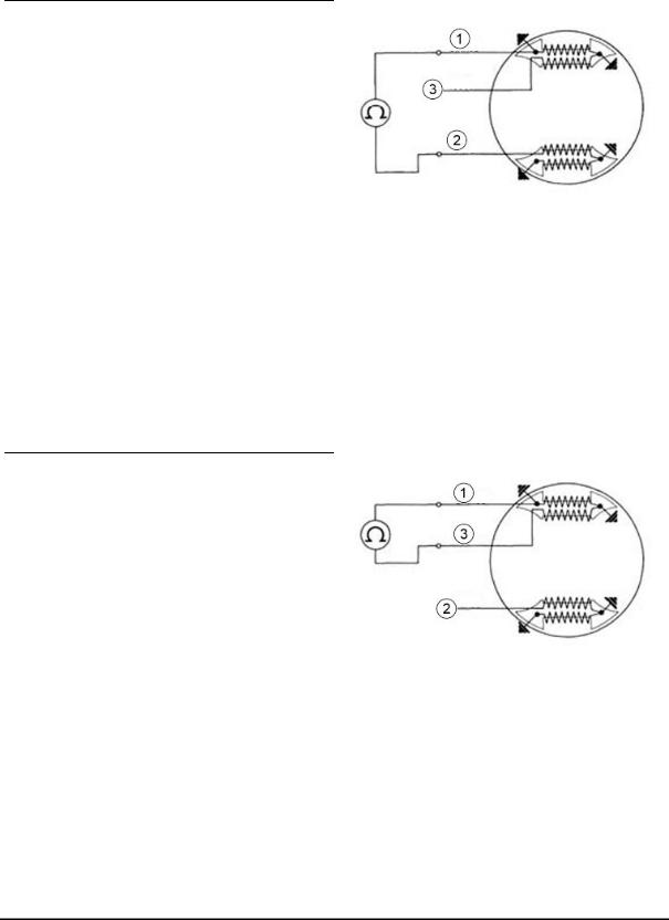
RULES TO BE FOLLOWED IN THE EVENT OF INTERVENTION ON THE ELECTRIC SYSTEM - APE TM
A) ESSENTIAL WARNINGS
The check or in any case the intervention on the circuits of the devices for the electronic ignition can be done with relative ease by the electronic repairers of Service Station Workshops; it is essential, however, that they take observe the notices below, since, in case of failure to observe, they could irreparably damage the devices.
All inspection operations of the system involving disconnection of cables (verification of the connections and devices that are part of the ignition circuit, therefore including the main key switch) must be made with the engine off: otherwise the control unit could be irreparably damaged.
The ignition circuit works on AC, and obviously, must be definitely separated from that of DC
In fact the latter, powered by the battery and dynamotor, serves only for the service user groups (city lights, stop, horn, lights, headlight, etc.).
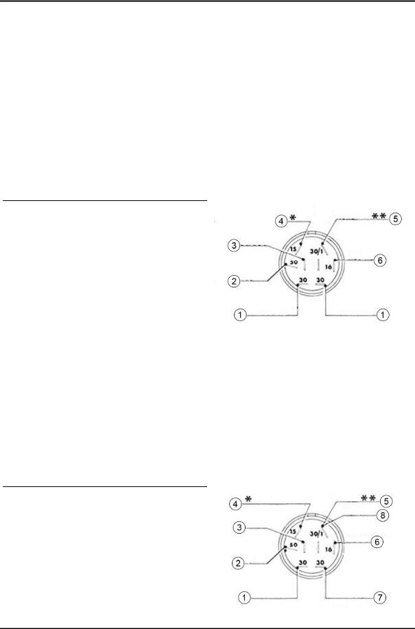
KEY:
1 = Red (direct current)
2 = White (direct current)
3 = Grey - Red (direct current)
4 = Purple (alternating current engine stop)
5 = Black (ground)
6 = White - Red (direct current)
*= Connection connected to the red cable of the condenser charging coil.
**= Connections with electronic ignition.
If there is a connection of two circuits, i.e., if the ignition one was routed by the DC, there would be instantaneous deterioration of the control unit. It is therefore necessary and important that, in case of removal or disconnection of cables, particularly of those which depend on the main key switch and the control unit, during reassembly pay attention to correctly reconnect each cable to the
GEN - 7
General guidelines |
APE TM Benzina |
|
|
corresponding terminal; for this purpose it is always advisable to consult the electrical circuit diagrams.
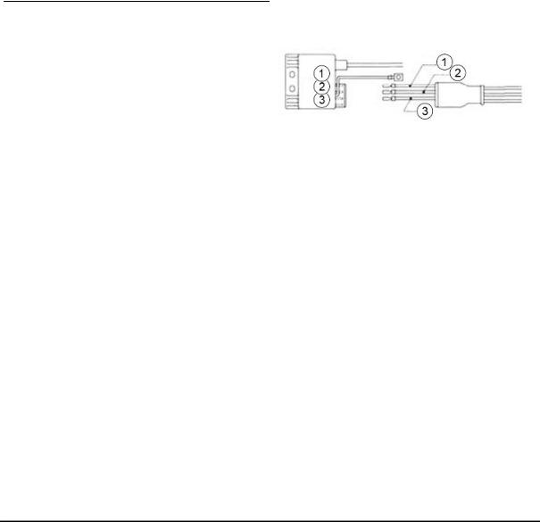
KEY:
1 = Red (direct current)
2 = White (direct current)
3 = Grey - Red (direct current)
4 = Purple (alternating current engine stop)
5 = Black (ground)
6 = White - Red (direct current)
7 = Grey (direct current)
8 = Black
*= Connection connected to the red cable of the condenser charging coil.
**= Connections with electronic ignition.
For obvious reasons it is essential that, in case of replacement of one or more devices in the system (main switch, stator unit of the flywheel, control unit) during reassembly, a device is used that is similar to the existing one: if in fact similar devices were used, but not specific to the same ignition system, they would not work, risking irreparable damage to the control unit.
KEY:
1 = White
2 = Red
3 = Green
B) INSPECTIONS TO BE PERFORMED IN THE EVENT OF IGNITION IRREGULARITIES
In the event of failure and abnormal operation of the ignition, whose causes are not detectable by a visual inspection, it is necessary first to replace the control unit with a corresponding, safely functional one. Remember that the disconnections and connections to replace the control unit must be performed when the engine is off.
GEN - 8
APE TM Benzina |
General guidelines |
|
|
If replacing restores the ignition operation, the fault lies in the control unit, which obviously needs to be replaced. In the event that the failure persists, it is necessary to carry out checks on the alternator and on the stator components as follows:
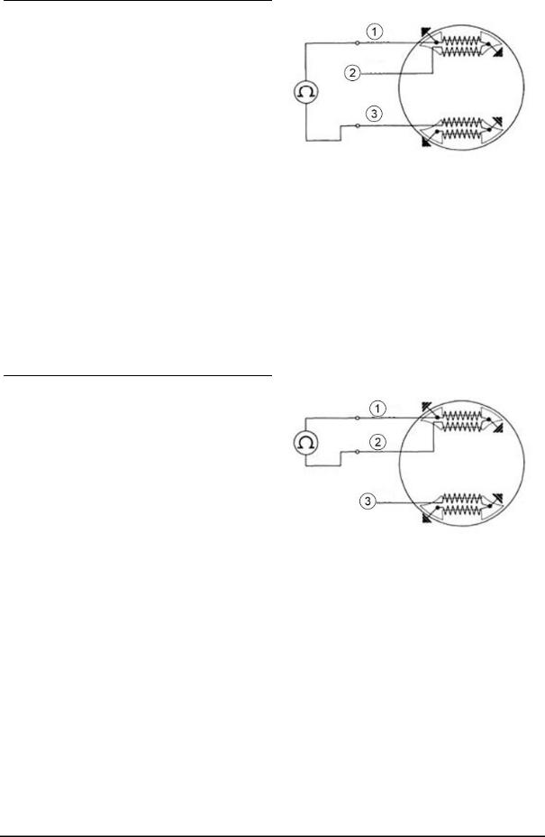
After a visual inspection of the connections, stator and couplings, measurements are carried out on the charging coil and the ignition coil using an Ohm meter, capable of detecting resistance from 1 to 1000 ohm, as follows:
- Connect the instrument between the WHITE cable and the RED cable; there must be continuity and ohmic value (430 to 480 ohm);
KEY:
1)White
2)Red
3)Green
- Connect the + terminal of the instrument with the WHITE cable and the - terminal of the instrument with the RED cable there must be continuity and ohmic value (7 to 9 ohm).
KEY:
1)White
2)Red
3)Green
If failures are detected in the inspections of the charging coil and ignition coil, proceed to replace the damaged parts.
If there is no tool available to check the stator, when it is established that the ignition problem is not related to the power control unit nor to other visible causes (bad connections, damaged cables, damaged spark plug), proceed to replace the complete stator. In relation to what described in the preceding paragraphs we recommend, therefore, to include in the control tools an Ohm meter with the characteristics outlined above.
C) IGNITION TIMING CHECK
GEN - 9
General guidelines |
APE TM Benzina |
|
|
The timing check may be useful for example if the motor is not operating properly (start-up difficulties; decreased performance and power; difficult or irregular recovery speed etc.); if the failure does not depend on the carburetion, it may be caused by irregularities of the ignition timing.
This possibility is, however, considered quite rare since, due to the characteristics of the ignition system, the timing adjustment remains unchanged over time; since the problem arises in most cases from irregular operation of the control unit, to be sure please follow the steps outlined on the side for verification of the aforementioned device.
If however, after checking the carburetion and the control unit, the desired improvements are not obtained and there is doubt whether the anomalies are due to the ignition timing, proceed to check the latter, operating as follows:.
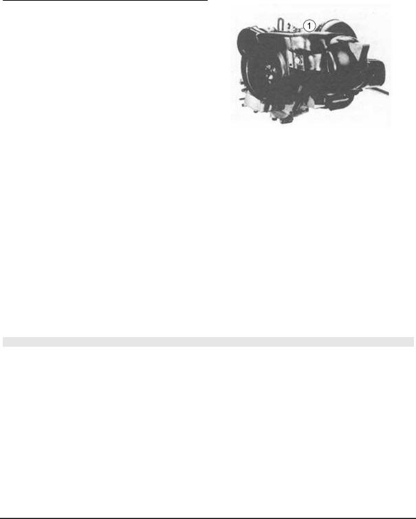
1) Insert, into the hole (1) a rod of Ø 5 mm.; run the engine manually until when the end of the rod, coming into correspondence with the other hole on the rotor, does not fit.
In this condition the engine is in ignition advance position.
2)Make a mark with white paint on the fan cover, in correspondence with the flap of the flywheel bearing the reference for the timing.
3)Connect a stroboscopic lamp (type TECNOTEST 130/P or other similar) at ignition; the connection will be made directly on the spark plug or on the H.V. cable, etc. depending on the type of stroboscopic lamp available and the specific operating instructions. Then start the engine and bring it to about 4000-5000 rpm.
4)The engine will be properly timed to the lamp when the two marks are aligned, or at most, moved to within a tolerance range of 4° (i.e., within 2° to the right and 2° to the left of alignment position).
5)If the mark of the flywheel rotor is shifted compared to the crankcase more than the allowed tolerance (or other major irregularities appear during the check), replace the stator or the control unit.
N.B.
FOR VEHICLES OF NEXT PRODUCTION, THE FAN COVER WILL BE FITTED WITH A REFERENCE FOR TIMING, SO THE OPERATIONS DESCRIBED IN POINTS 1 AND 2 WILL NOT BE NECESSARY.
RULES TO BE FOLLOWED IN THE EVENT OF INTERVENTION ON THE ELECTRIC SYSTEM - APE TM P703 FL2
A) ESSENTIAL WARNINGS
The check or in any case the intervention on the circuits of the devices for the electronic ignition can be done with relative ease by the electronic repairers of Service Station Workshops; it is essential, however, that they take observe the notices below, since, in case of failure to observe, they could irreparably damage the devices.
GEN - 10
APE TM Benzina |
General guidelines |
|
|
All inspection operations of the system involving disconnection of cables (verification of the connections and devices that are part of the ignition circuit, therefore including the main key switch) must be made with the engine off: otherwise the control unit could be irreparably damaged.
The ignition circuit works on AC, and obviously, must be definitely separated from that of DC
In fact the latter, powered by the battery and dynamotor, serves only for the service user groups (city lights, stop, horn, lights, headlight, etc.).
KEY:
1 = Red (direct current)
2 = White (direct current)
3 = Red (direct current)
4 = Purple (alternating current engine stop)
5 = Black (ground)
*= Connection connected to the fuses.
**= Connection connected to the starter relays.
***= Connection connected to the white-red cable of the light switch.
****= Connections with electronic ignition.
*****= Connection connected to the voltage regulator.
If there is a connection of two circuits, i.e., if the ignition one was routed by the DC, there would be instantaneous deterioration of the control unit. It is therefore necessary and important that, in case of removal or disconnection of cables, particularly of those which depend on the main key switch and the control unit, during reassembly pay attention to correctly reconnect each cable to the corresponding terminal; for this purpose it is always advisable to consult the electrical circuit diagrams.
For obvious reasons it is essential that, in case of replacement of one or more devices in the system (main switch, stator unit of the flywheel, control unit) during reassembly, a device is used that is similar to the existing one: if in fact similar devices were used, but not specific to the same ignition system, they would not work, risking irreparable damage to the control unit.
B) INSPECTIONS TO BE PERFORMED IN THE EVENT OF IGNITION IRREGULARITIES
GEN - 11
General guidelines |
APE TM Benzina |
|
|
In the event of failure and abnormal operation of the ignition, whose causes are not detectable by a visual inspection, it is necessary first to replace the control unit with a corresponding, safely functional one. Remember that the disconnections and connections to replace the control unit must be performed when the engine is off.
If replacing restores the ignition operation, the fault lies in the control unit, which obviously needs to be replaced. In the event that the failure persists, it is necessary to carry out checks on the alternator and on the stator components as follows:
After a visual inspection of the connections, stator and couplings, measurements are carried out on the charging coil and the ignition coil using an Ohm meter, capable of detecting resistance from 1 to 1000 ohm, as follows:
- Connect the instrument between the WHITE cable and the RED cable, there must be continuity and ohmic value (430 to 480 ohm);
KEY:
1 = White
2 = Red
3 = Green
- Connect the + terminal of the instrument with the WHITE cable and the - terminal of the instrument with the GREEN cable there must be continuity and ohmic value (7 to 9 ohm).
KEY:
1 = White
2 = Red
3 = Green
If failures are detected in the inspections of the charging coil and ignition coil, proceed to replace the damaged parts.
If there is no tool available to check the stator, when it is established that the ignition problem is not related to the power control unit nor to other visible causes (bad connections, damaged cables, damaged spark plug), proceed to replace the complete stator. In relation to what described in the preceding
GEN - 12
APE TM Benzina |
General guidelines |
|
|
paragraphs we recommend, therefore, to include in the control tools an Ohm meter with the characteristics outlined above.
C) IGNITION TIMING CHECK
The timing check may be useful for example if the motor is not operating properly (start-up difficulties; decreased performance and power; difficult or irregular recovery speed etc.); if the failure does not depend on the carburetion, it may be caused by irregularities of the ignition timing.
This possibility is, however, considered quite rare since, due to the characteristics of the ignition system, the timing adjustment remains unchanged over time; since the problem arises in most cases from irregular operation of the control unit, to be sure please follow the steps outlined on the side for verification of the aforementioned device.
If however, after checking the carburetion and the control unit, the desired improvements are not obtained and there is doubt whether the anomalies are due to the ignition timing, proceed to check the latter, operating as follows:.
1) Insert, into the hole (1) a rod of Ø 5 mm.; run the engine manually until when the end of the rod, coming into correspondence with the other hole on the rotor, does not fit.
In this condition the engine is in ignition advance position.
2)Make a mark with white paint on the fan cover, in correspondence with the flap of the flywheel bearing the reference for the timing.
3)Connect a stroboscopic lamp (type TECNOTEST 130/P or other similar) at ignition; the connection will be made directly on the spark plug or on the H.V. cable, etc. depending on the type of stroboscopic lamp available and the specific operating instructions. Then start the engine and bring it to about 4000 - 5000 rpm.
4)The engine will be properly timed to the lamp when the two marks are aligned, or at most, moved to within a tolerance range of 4° (i.e., within 2° to the right and 2° to the left of alignment position).
5)If the mark of the flywheel rotor is shifted compared to the crankcase more than the allowed tolerance (or other major irregularities appear during the check), replace the stator or the control unit.
N.B.
FOR VEHICLES OF NEXT PRODUCTION, THE FAN COVER WILL BE FITTED WITH A REFERENCE FOR TIMING, SO THE OPERATIONS DESCRIBED IN POINTS 1 AND 2 WILL NOT BE NECESSARY.
GEN - 13

INDEX OF TOPICS
CHARACTERISTICS |
CH |

APE TM Benzina |
Characteristics |
|
|
Characteristics
SIZES
|
millimetres |
Deck |
Long |
Van |
Tipper |
|
|
|
Deck |
|
|
(1) |
Length |
3175 |
3375 |
3175 |
3230 |
(2) |
Width |
1480 |
- |
- |
1510 |
(3) |
Height |
1630 |
- |
1750 |
1630 |
(4) |
Wheelbase |
2170 |
2170 |
2170 |
2170 |
(5) |
Track |
1300 |
1300 |
1300 |
1300 |
(6) |
Turning spokes |
3300 |
3300 |
3300 |
3300 |
WEIGHTS
(*) = without the driver
(*) = including the driver
Kilograms (kg) |
Deck |
Long |
Van |
Tipper |
|
|
Deck |
|
|
Dry weight (*) |
445 |
450 |
465 |
465 |
Vehicle weight in running order (with refuelling, tools and accessories) |
1160 |
1160 |
1160 |
1160 |
Load capacity (**) |
715 |
710 |
695 |
695 |
TECHNICAL DATA - CHASSIS |
|
Specification |
Desc./Quantity |
Chassis |
Sheet steel body and a single central longitudinal arm (inte- |
|
grated structure). Removable deck integrated into the struc- |
|
ture. |
Driver's cab |
Welded to the chassis. |
Seats in driving cab |
Two. |
TECHNICAL DATA - ENGINE |
|
Specification |
Desc./Quantity |
Matriculation data |
The identification codes consist of a prefix (ATM2T on the |
|
chassis, ATM2M on the engine) and a number. |
Engine |
Single-cylinder, 2-stroke engine, with "rotating" timing and with |
|
three transfer ducts, with transmission and differential grouped |
|
on the axis of the rear wheels. |
Engine capacity |
217.9 cm³ |
Bore X Stroke |
68 x 60 |
Compression ratio |
8.6 : 1 |
Ignition advance |
14° ± 1°30' before T.D.C.: |
Carburettor |
Dell'Orto SHB 22/22. |
Fuel |
Pure petrol with separate engine lubrication, "LS" device. |
Spark plug |
Marelli CW7N, or Bosch W4AC; Lodge 3HN; Champion L82; |
|
AC430Z; NGK B7HS. |
Maximum speed (CUNA STANDARDS) |
60÷65 km/h. |
Air filter |
At the intake of the type with paper cartridge filter. |
Cartridge |
AC AIRAC FLAT PACK. |
Consumption (CUNA) |
~4.3 litres per 100 km. |
Km range |
Around 330 Km. |
TRANSMISSION |
|
Specification |
Desc./Quantity |
Gear ratio First |
1/48.47 |
Gear ratio Second |
1/26.54 |
Gear ratio Third |
1/15.56 |
Gear ratio Fourth |
1/9.16 |
Gear ratio Reverse |
1/80.78 |
CH - 15

Characteristics |
APE TM Benzina |
|
|
|
STEERING |
|
Specification |
Desc./Quantity |
|
Steering |
Built with tube pivoted on the arm with front wheel-holder os- |
|
|
cillating hub. |
|
|
SUSPENSION |
Specification |
Desc./Quantity |
Front suspension |
Built using helical spring. |
Rear suspension |
Built with flexible rubber components in progressive rate. Sus- |
|
pensions consist of hydraulic shock absorbers. |
|
TYRES |
Specification |
Desc./Quantity |
Wheel rim |
From 3.50". |
Front wheel and spare wheel |
"Normal" type 4.00-12 C- PR6. |
Rear wheels |
"Radial" type 4.00-12 C- PR6. (for example Michelin C-XZX |
|
PR.6. for deck, van, tipper, Urban Cleansing van and cabriolet |
|
versions). |
|
"Radial" type 4.00-R12 C- PR8. (for example Michelin C-XZX |
|
PR.8. for versions with external fixed elaborations and those |
|
with hydraulic tipping). |
Front tyre pressure |
2.8 bar |
Rear tyres - inflation pressure |
4.5 bar |
N.B.:
When installing the spare wheel in place of one of the rear wheels (for example due to a puncture) it is recommended to replace it as soon as possible by reinstalling the "radial" tyre which is more suitable for use.
It is not advisable to install the radial tyre on the front wheel as there would be excessive sensitivity, especially when driving on twisting or bumpy roads.
REFILLING
(*)= specific for versions with tipper deck. |
|
|
|
|
Litres (l) |
Deck |
Long |
Van |
Tipper |
|
|
Deck |
|
|
Fuel tank (reserve) |
15 (3.5) |
15 (3.5) |
15 (3.5) |
15 (3.5) |
Engine oil (reserve) |
3.0 (0.75) |
3.0 (0.75) |
3.0 (0.75) |
3.0 (0.75) |
Hydraulic oil (*) |
3.0 |
3.0 |
3.0 |
3.0 |
DIMENSIONS - APE TM KAT - APE TM P703 FL2
|
millimetres |
Deck |
Long |
Van |
Tipper |
Motor |
|
|
|
Deck |
|
|
chassis |
(1) |
Length |
3175 |
3390 |
3210 |
3225 |
3150 |
(2) |
Width |
1480 |
- |
- |
1500 |
|
(3) |
Height |
1630 |
1630 |
1780 |
1630 |
|
(4) |
Wheelbase |
2170 |
2170 |
2170 |
2170 |
|
(5) |
Track |
1300 |
1300 |
1300 |
1300 |
|
(6) |
Turning spokes |
3300 |
3300 |
3300 |
3300 |
|
WEIGHTS - APE TM KAT - APE TM P703 FL2
(*)= without the driver
(*)= including the driver
Kilograms (kg) |
Deck |
Long |
Van |
Tipper |
|
|
Deck |
|
|
Dry weight (*) |
465 |
465 |
505 |
505 |
Vehicle weight in running order (with refuelling, tools and accessories) |
1270 |
1270 |
1270 |
1270 |
Load capacity (**) |
805 |
805 |
765 |
765 |
CH - 16

APE TM Benzina |
Characteristics |
|
|
TECHNICAL DATA - CHASSIS - APE TM KAT - APE TM P703 FL2
Specification |
Desc./Quantity |
Chassis |
Sheet steel body and a single central longitudinal arm (inte- |
|
grated structure). |
Versions |
Sheet metal deck, integrated into the structure. |
|
Long deck. |
|
Aluminium alloy deck, hydraulic tipper for engine inspection. |
Driver's cab |
Welded to the chassis. |
Seats in driving cab |
Two. |
TECHNICAL DATA - ENGINE - APE TM KAT
Specification |
Desc./Quantity |
Matriculation data |
The identification codes consist of a prefix (ATM2T on the |
|
chassis, ATM2M on the engine) and a number. |
Engine |
Single-cylinder, 2-stroke engine, with "rotating" timing and with |
|
three transfer ducts, with transmission and differential grouped |
|
on the axis of the rear wheels. |
Engine capacity |
217.9 cm³ |
Bore X Stroke |
68 x 60 |
Compression ratio |
8.6 : 1 |
Ignition advance |
14° ± 1°30' before T.D.C.: |
Carburettor |
Dell'Orto SHB 22/22. |
Fuel |
Pure petrol with separate engine lubrication, "LS" device. |
Spark plug |
Champion RL78C; NGK BR8HS. |
Maximum speed (CUNA STANDARDS) |
60÷65 km/h. |
Air filter |
At the intake of the type with paper cartridge filter. |
Consumption (CUNA) |
~4.1 litres per 100 km. |
Km range |
Around 330 Km. |
TECHNICAL DATA - ENGINE - APE TM P703 FL2
Specification |
Desc./Quantity |
Matriculation data |
The identification codes consist of a prefix (ATM2T on the |
|
chassis, ATM2M on the engine) and a number. |
Engine |
Single-cylinder, 2-stroke engine, with "rotating" timing and with |
|
three transfer ducts, with transmission and differential grouped |
|
on the axis of the rear wheels. |
Engine capacity |
217.9 cm³ |
Bore X Stroke |
68 x 60 |
Compression ratio |
8.6 : 1 |
Ignition advance |
14° ± 1°30' before T.D.C.: |
Carburettor |
Dell'Orto SHB 22/22. |
Fuel |
Pure petrol with separate engine lubrication, "LS" device. |
Spark plug |
Bosch W4AC; Lodge 3HN; Champion L78C AC430Z. |
Maximum speed (CUNA STANDARDS) |
60÷65 km/h. |
Air filter |
At the intake of the type with paper cartridge filter. |
Consumption (CUNA) |
~4.1 litres per 100 km. |
Km range |
Around 330 Km. |
TRANSMISSION - APE TM KAT - APE TM P703 FL2
Specification |
Desc./Quantity |
Gear ratio First |
1/48.47 |
Gear ratio Second |
1/26.54 |
Gear ratio Third |
1/15.56 |
Gear ratio Fourth |
1/9.16 |
Gear ratio Reverse |
1/80.78 |
STEERING - APE TM KAT - APE TM P703 FL2
Specification |
Desc./Quantity |
Steering |
Built with tube pivoted on the arm with front wheel-holder os- |
|
cillating hub. |
CH - 17

Characteristics |
APE TM Benzina |
|
|
SUSPENSION - APE TM KAT - APE TM P703 FL2
Specification |
Desc./Quantity |
|
Front suspension |
Built using helical spring. |
|
Rear suspension |
Built with flexible rubber components in progressive rate. Sus- |
|
|
pensions consist of hydraulic shock absorbers. |
|
TYRES - APE TM KAT - APE TM P703 FL2
Specification |
Desc./Quantity |
Wheel rim |
From 3.50". |
Front tyre (handlebar version) |
4.00-12CNTL |
Rear tyre (handlebar version) |
125R12C XZX TL |
Front tyre (steering wheel version) |
125R12C XZX TL |
Rear tyre (steering wheel version) |
125R12C XZX TL |
Front tyre pressure |
2.5 bar |
Rear tyres - inflation pressure |
4.5 bar |
REFILLING - APE TM KAT - APE TM P703 FL2
(*)= specific for versions with tipper deck.
|
Litres (l) |
Deck |
|
Long |
Van |
Tipper |
|
|
|
|
|
|
Deck |
|
|
|
|
|
Fuel tank (reserve) |
15 (3.5) |
|
15 (3.5) |
|
15 (3.5) |
15 (3.5) |
|
|
Engine oil (reserve) |
3.2 (0.75) |
|
3.2 (0.75) |
|
3.2 (0.75) |
3.2 (0.75) |
|
|
Hydraulic oil (reserve) (*) |
15 (3.2) |
|
15 (3.2) |
|
15 (3.2) |
15 (3.2) |
|
|
|
|
|
|
|
|
|
|
Tightening torques |
|
|
|
|
|
|
|
|
|
ENGINE UNIT |
|
|
|
|
|
|
|
|
Name |
|
Torque in Nm |
|
|
|
||
|
Transmission cross control stem |
35 to 40 Nm (a) |
|
|
||||
|
3rd and 4th speed cross control stem |
19 to 21 Nm (b) |
|
|
||||
|
1st and 2nd speed cross control stem |
25 to 30 Nm (b) |
|
|
||||
|
Spark plug |
|
|
18 to 24 Nm |
|
|
|
|
|
Bolts locking dynamotor to differential crankcase |
|
|
30 to 35 Nm |
|
|
|
|
|
Bolts locking dynamotor to engine crankcase |
|
|
20 to 25 Nm |
|
|
|
|
|
Clutch assembly locking nut |
|
180 to 220 Nm |
|
|
|
||
|
Multi-gear pin nut |
|
|
35 to 40 Nm |
|
|
|
|
|
Fan flywheel locking nut |
|
|
60 to 65 Nm |
|
|
|
|
|
Silencer manifold fixing nut |
|
|
19 to 21 Nm |
|
|
|
|
|
Silencer to crankcase fixing bolts |
|
|
18 to 22 Nm |
|
|
|
|
|
Clutch cover fixing bolt |
|
|
13 to 17 Nm |
|
|
|
|
|
Cylinder head fixing bolt |
|
|
20 to 23 Nm |
|
|
|
|
|
Engine to deck fixing bolt |
|
|
20 - 25 Nm |
|
|
|
|
|
Spring line to frame fixing bolt |
|
|
20 - 25 Nm |
|
|
|
|
|
Spring line to frame anchor bolt |
|
|
20 to 25 Nm |
|
|
|
|
|
Oil drain plug |
|
|
22 to 25 Nm |
|
|
|
|
|
Bolt connecting the crankcase halves |
|
|
13 to 15 Nm |
|
|
|
|
|
Dynamotor pulley lock nut |
|
|
35 to 40 Nm |
|
|
|
|
|
Crankcase admission joint lock bolts |
|
|
14 to 18 Nm |
|
|
|
|
|
Change control support lock bolts |
|
|
14 to 18 Nm |
|
|
|
|
|
(a)= Specific for version with handlebar |
|
|
|
|
|
|
|
|
(b)= Specific for version with steering wheel |
|
|
|
|
|
|
|
|
DIFFERENTIAL UNIT |
|
|
|
|
|
|
|
|
Name |
|
Torque in Nm |
|
|
|
||
|
Differential box toothed sprocket lock bolts |
|
|
54 to 64 Nm |
|
|
|
|
|
Differential cover fixing bolt |
|
|
30 to 40 Nm |
|
|
|
|
CH - 18

APE TM Benzina |
Characteristics |
|
|
FRONT SUSPENSION UNIT
Name |
Torque in Nm |
Shock absorber upper anchoring nut |
30-40 |
Shock absorber lower anchoring nut |
100-120 |
Steering upper bearing lock gear |
50 to 70 |
Wheel rim to drum locking |
60-70 |
Wheel locking centre nut |
100-120 |
Shoes self-centring plate lock nuts |
20 - 25 |
REAR SUSPENSION UNIT
Name |
Torque in Nm |
Wheel to drum lock nut |
60-70 |
Drum centre lock nut |
200 to 240 |
Shock absorber lower lock nut |
100 to 140 Nm |
Shock absorber upper lock nut |
30-40 |
Swinging arm lock nut |
40-50 Nm |
Flexible coupling lock nut |
40 - 50 |
Hub to axle shaft lock nut |
50-70 |
Hub to wheel axle lock nut |
140-180 |
Hub to swinging arm lock nut |
40 - 50 |
Shoes self-centring plate lock nut |
18 to 20 Nm |
FRAME ASSEMBLY
Name |
Torque in Nm |
|
Handle bar to steering tube lock bolts |
42 to 52 (a) |
|
Steering control lever to steering tube lock bolts |
30 to |
35 |
Steering housing lock nuts |
20 to 25 (b) |
|
Steering wheel lock nut |
30 to 35 (b) |
|
Rack pressure roller lid lock nuts |
8 to 12 (b) |
|
Pressure roller adjustment screw lock nut |
40 to 60 (b) |
|
Lever holder locking screw |
7 to 8.5 |
|
Brake oil pump piston end stroke screw |
6 to 10 Nm |
|
Pedal assembly bolt lock nut |
15 to |
25 |
Stop switch |
1.5 to 3 |
|
Cab doors lock bolt |
23 to |
30 |
Windshield wiper motor lock |
8 to |
9 |
Brake pump body lock bolts |
12 to 20 (a) |
|
Brake pump body lock bolts |
8 to 12 |
|
Floor to cab panel lock bolts |
20 - 25 |
|
Floor to centre cross member lock nuts |
20 - 25 |
|
(a) Specific for versions with handlebar
(a) Specific for versions with steering wheel
Vehicle overhaul data
Assembly clearances
|
SHOULDER RINGS |
Specification |
Desc./Quantity |
Shoulder ring (Nominal sizes) |
B= 1 +0 -0.06 (mm) |
CH - 19
Characteristics |
APE TM Benzina |
|
|
SHOULDER RING - CLEARANCE "A" UPON FITTING
Name |
Description |
Dimensions |
Initials |
Quantity |
Shoulder ring |
1st Oversize |
1.1 +0 -0.06 |
|
0.15 to 0.50 |
Shoulder ring |
2nd Oversize |
1.2 +0 -0.06 |
|
0.15 to 0.50 |
Shoulder ring |
3rd Oversize |
1.3 +0 -0.06 |
|
0.15 to 0.50 |
Shoulder ring |
4th Oversize |
1.5 +0 -0.06 |
|
0.15 to 0.50 |
For the clearance check, use the specific equipment.
N.B.
IF YOU DO NOT GET THE CLEARANCE "A" WITH SHOULDER RING "B", REPLACE THE LATTER WITH A RING LARGE ENOUGH TO GET THE REQUIRED CLEARANCE.
Specific tooling
T.0060824 Control probe axle clearance gear change
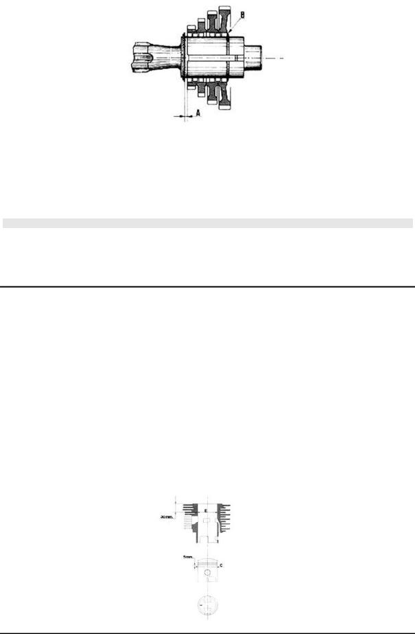
Cylinder-piston oversizes
FITTING CLEARANCES
Pistons and cylinders supplied as spare parts by the Manufacturer are marked with the letters of the alphabet. When both pistons and cylinders are replaced, the pieces with the same letter must be matched.
NORMAL CYLINDERPISTON NOMINAL SIZES
Specification |
Desc./Quantity |
Normal cylinder nominal sizes |
E=68 +0.025 - -0.005 |
Normal piston nominal sizes |
C=67.76 +0.025 -0.005 |
CYLINDER COUPLING - PISTON
Name |
Initials |
Cylinder |
Piston |
Play on fitting |
Coupling: |
1st Oversize |
68.20 to 68.22 |
67.96 to 67.98 |
0.24 |
Coupling: |
2nd Oversize |
68.40 to 68.42 |
68.16 to 68.18 |
0.24 |
Coupling: |
3rd Oversize |
68.60 to 68.62 |
68.36 to 68.38 |
0.24 |
CH - 20
APE TM Benzina |
Characteristics |
|
|
If, however, the cylinder should be increased, the size "E" (see figure) must exceed the size "C" of the piston to be installed (marked on the piston itself) of the indicated value, "Cylinder clearance - piston".
Fitting clearance
Cylinder - piston clearance 0.24
CAUTION
AT REPLACEMENT OF PISTON IN THE CYLINDER, MAKE SURE THAT THE ARROW STAMPED ON THE PISTON SPROCKET IS FACING THE EXHAUST PORT OF THE CYLINDER.
Piston ring oversizes
|
SEALING RINGS |
Specification |
Desc./Quantity |
Seal ring (Nominal sizes) |
Diameter = 68 (mm) |
CLEARANCE "A" UPON FITTING
Name |
Description |
Dimensions |
Initials |
Quantity |
Sealing ring |
1st Oversize |
68.20 |
|
0.25 to 0.40 |
Sealing ring |
2nd Oversize |
68.40 |
|
0.25 to 0.40 |
Sealing ring |
3rd Oversize |
68.60 |
|
0.25 to 0.40 |
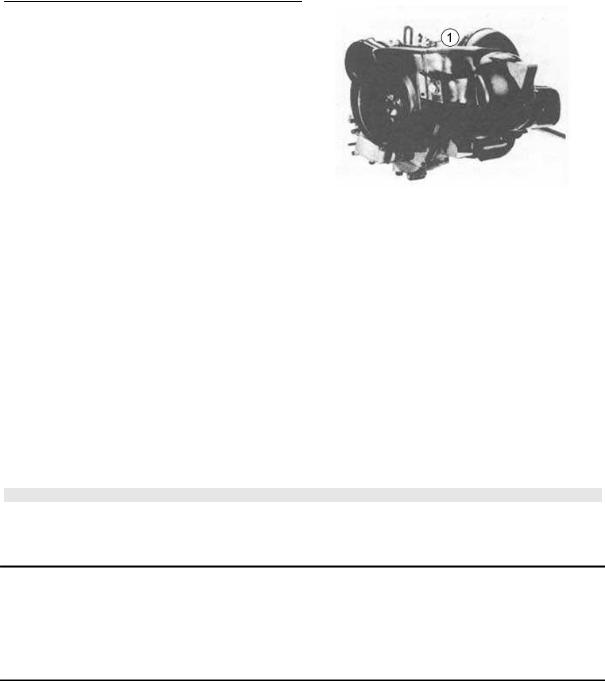
Crankshaft alignment check
With the proper equipment (1), check that the eccentricity of the surface of Ø "E" and "F" are contained within 0.03 mm. (the maximum reading limit on the dial gauge clock); also check the eccentricity of the diameter "D", for which there shall be a maximum reading of 0.02 mm.
In the case of eccentricities not much greater than that prescribed, perform the straightening of the shaft by means of counterweights with a wedge, or tightening it in a vice (equipped with aluminium bushings) as needed.
CH - 21
Characteristics |
APE TM Benzina |
|
|
Specific tooling
19.1.20074 Crankshaft checking tool
Rod small end bushing - Pin
CONNECTING ROD SMALL END - PIN - ROLLER CAGE
The connecting rods and cages are divided into 4 categories (marked with incisions at the foot of the same connecting rod and on the cage frames).
CONNECTING ROD - ROLLER CAGE
Connecting rod |
Roller cage |
1st category |
4th category |
2nd category |
3rd category |
3rd category |
2nd category |
4th category |
1st category |
|
|
CAUTION |
|
IN CASE OF NOISE, USE CAGE OF LOWER CATEGORY.
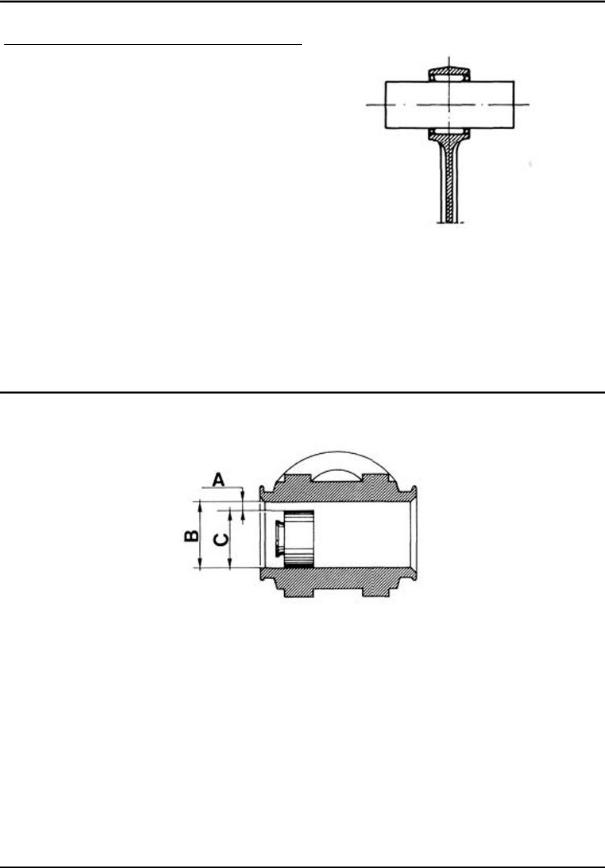
Oil pump
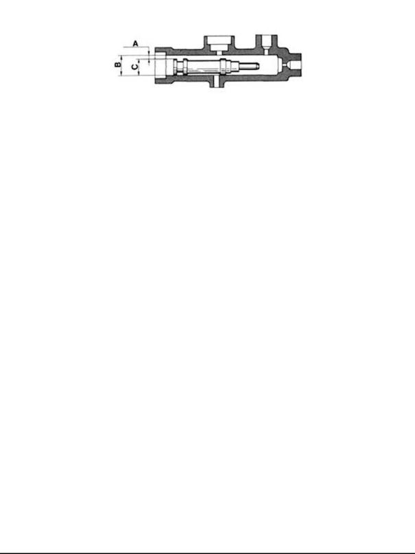
FRONT BRAKE CYLINDER - CLEARANCE "A" FOR FITTING
Name |
Description |
Dimensions |
Initials |
Quantity |
Cylinder |
|
B=22.225 -0 +0.033 |
|
0.040 to 0.106 |
Piston |
|
C=22.225 -0.040 -0.073 |
|
0.040 to 0.106 |
REAR BRAKE CYLINDERS - CLEARANCE "A" FOR FITTING
Name |
Description |
Dimensions |
Initials |
Quantity |
Cylinder |
|
B=25.40 -0 +0.033 |
|
0.150 to 0.125 |
Piston |
|
C=25.40 -0.040 -0.092 |
|
0.150 to 0.125 |
CH - 22
APE TM Benzina |
Characteristics |
|
|
FRONT AND REAR BRAKE CYLINDERS - CLEARANCE "A" FOR FITTING - APE TM P703
FL2
|
Name |
Description |
Dimensions |
Initials |
Quantity |
|
|
Cylinder |
|
B=25.40 -0 +0.033 |
|
0.040 to 0.125 |
|
|
Piston |
|
C=25.40 -0.040 -0.092 |
|
0.040 to 0.125 |
|
|
|
|
|
|
|
|
CLEARANCE "A" UPON FITTING
|
Name |
Description |
Dimensions |
Initials |
Quantity |
|
|
Cylinder |
|
B=19 +0.033 -0 |
|
0.040 to 0.106 |
|
|
Piston |
|
C=19 +0.040 -0.073 |
|
0.040 to 0.106 |
|
|
|
|
|
|
|
|
CH - 23

INDEX OF TOPICS
SPECIAL TOOLS |
ST |
APE TM Benzina |
Special tools |
|
|
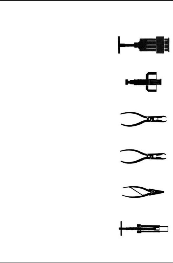
Tooling
|
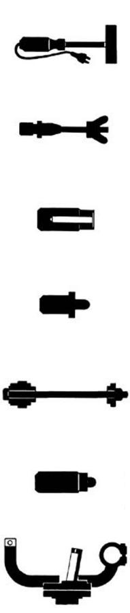
SPECIAL TOOLS |
Stores code |
Description |
T.0014499 |
Bearing extractor |
|
|
T.0021467 |
Bearing extractor |
T.0017104 |
Pliers for circlips |
|
|
T.0022465 |
Pliers for circlips |
0023638 |
Pliers for circlips |
|
|
T.0018119 |
Tool for fitting shafts |
ST - 25
Special tools |
APE TM Benzina |
|
|
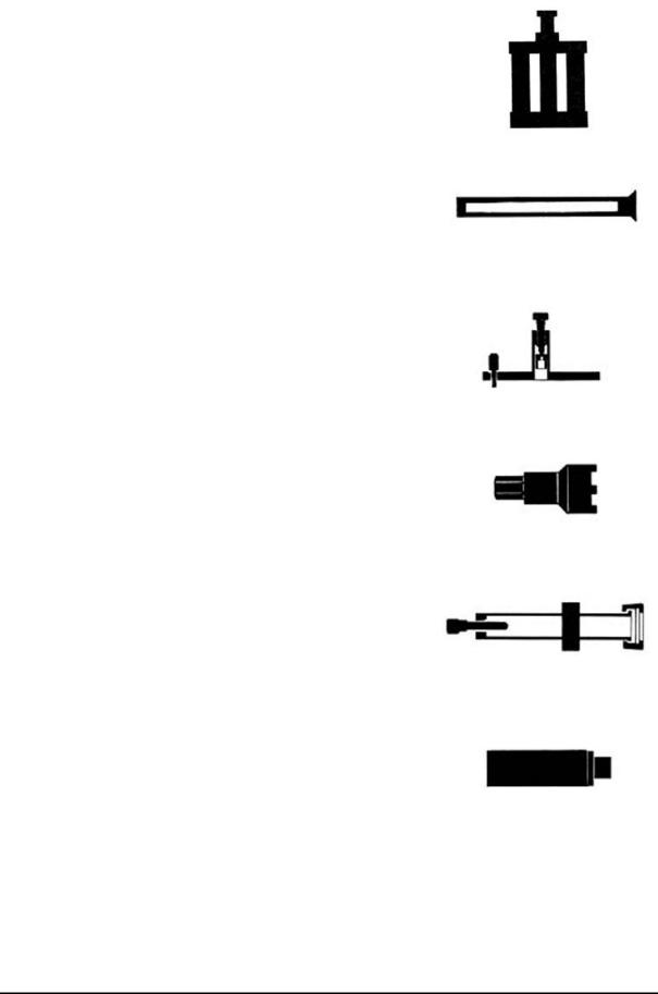
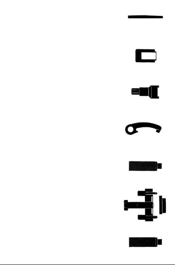
Stores code |
Description |
19.1.20000 |
Tool for front suspension overhaul |
|
|
19.1.20004 |
Tool for disassembling steering bearing |
|
from the frame |
19.1.20024 |
Crankshaft removal tool |
|
|
19.1.20041 |
Steering upper bearing ring nut gear |
|
wrench |
19.1.20042 |
Extract the bottom seat of the steering |
|
bottom bearing |
|
|
19.1.20043 |
Rear wheel hub roller bearing fitting |
|
punch |
19.1.20044 |
Front wheel hub roller bearing fitting |
|
punch |
ST - 26
APE TM Benzina |
Special tools |
|
|
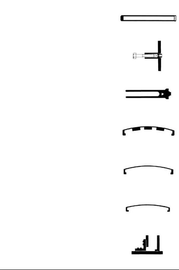
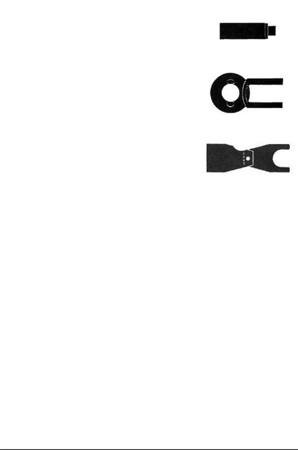
Stores code |
Description |
19.1.20045 |
Tool for fitting steering lower bearing low- |
|
er seat |
19.1.20046 |
Clutch puller |
|
|
19.1.20047 |
Pliers for chamfering nuts |
19.1.20049 |
Window positioning tool |
|
|
19.1.20050 |
Lower retainer clamp for strip |
19.1.20051 |
Upper retainer clamp for strip |
|
|
19.1.20074 |
Crankshaft checking tool |
ST - 27
Special tools |
APE TM Benzina |
|
|
Stores code |
Description |
0019978 |
Oven |
|
|
T.0020322 |
Clutch removal and refitting tool |
T.0020781 |
Bearings Fitting Punch |
|
|
T.0021071 |
Punch to fit bearings and seal rings |
T.0021330 |
Steering seats fitting tool |
|
|
T.0023589 |
Punch for bearings and sealing rings |
|
T.0025095 |
Engine support plane |
|
|
|
|
|
|
|
|
|
ST - 28
APE TM Benzina |
Special tools |
|
|
Stores code |
Description |
T.0025127 |
Wedge |
T.0027338 |
Punch to fit sealing rings |
|
|
T.0030632 |
Wrench for helical gear nut |
T.0031729 |
Clutch stop key |
|
|
T.0033970 |
Punch for fitting roller bearings |
T.0035731 |
Flywheel extractor and differential hous- |
|
ing |
|
|
T.0039152 |
Punch for roller bearing |
ST - 29
Special tools |
APE TM Benzina |
|
|
Stores code |
Description |
T.0039153 |
Punch for roller bearing |
|
|
T.0043062 |
Stop key of flywheel and dynamotor pul- |
|
ley |
|
T.0060824 |
Control probe axle clearance gear |
|
|
|
change |
|
|
|
|
|
|
|
|
|
ST - 30
 Loading...