


LUM MP3 300 YOURBAN RL-NRL 2011

Piaggio would like to thank you
for choosing one of its products. We have prepared this manual to help you to get the very best from your vehicle. Please read it carefully before riding
the vehicle for the first time. It contains information, tips and precautions for using your vehicle. It also describes features, details and devices to assure
you that you have made the right choice. We believe that if you follow our suggestions, you will soon get to know your new vehicle and it will serve you
well for a long time to come. This booklet forms an integral part of the vehicle; should the vehicle be sold, it must be transferred to the new owner.
LUM MP3 300 YOURBAN RL-NRL (2011)
Ed. 2

The instructions given in this manual are intended to provide a clear, simple guide to using your vehicle; this booklet also details routine maintenance
procedures and regular checks that should be carried out on the vehicle at an authorised Dealer or Service Centres. The booklet also contains
instructions for simple repairs. Any operations not specifically described in this booklet require the use of special tools and/or particular technical
knowledge: to carry out these operations, refer to any authorised Dealer or Service Centres.
2
Personal safety
Failure to completely observe these instructions will result in serious risk of personal
injury.
Safeguarding the environment
Sections marked with this symbol indicate the correct use of the vehicle to prevent dam-
aging the environment.
Vehicle intactness
The incomplete or non-observance of these regulations leads to the risk of serious
damage to the vehicle and sometimes even the invalidity of the guarantee.
The signs that you see on this page are very important. They are used to highlight parts
of the booklet that should be read with particular care. The different symbols are used
to make each topic in the manual simple and quick to locate.
3

4

INDEX
VEHICLE...................................................................................... 7
Dashboard................................................................................ 9
Analogue instrument panel....................................................... 11
Clock......................................................................................... 12
Digital lcd display...................................................................... 13
Maintenance icons................................................................ 14
*MODE* button...................................................................... 14
Key switch................................................................................. 15
Locking the steering wheel.................................................... 15
Releasing the steering wheel................................................ 15
Switch direction indicators........................................................ 16
Horn button............................................................................... 16
Light switch............................................................................... 17
Emergency flashing light button................................................ 17
Start-up button.......................................................................... 18
Engine stop button.................................................................... 18
Front suspension unlock-lock switch........................................ 19
The immobilizer system............................................................ 19
Keys...................................................................................... 19
Immobilizer device enabled indicator led.............................. 20
Operation............................................................................... 20
Programming the immobilizer system................................... 21
Accessing the fuel tank............................................................. 23
Opening the saddle............................................................... 23
Identification.............................................................................. 24
Bag clip..................................................................................... 25
USE.............................................................................................. 27
Checks...................................................................................... 28
Refuelling.................................................................................. 28
Tyre pressure............................................................................ 30
Shock absorbers adjustment.................................................... 32
Running in................................................................................. 33
Starting up the engine............................................................... 33
Precautions........................................................................... 35
Stopping the engine.................................................................. 36
Stand......................................................................................... 37
Automatic transmission............................................................. 37
Safe driving............................................................................... 38
Front suspension locking system.............................................. 40
Parking brake............................................................................ 44
MAINTENANCE........................................................................... 45
Engine oil level.......................................................................... 46
Engine oil level check............................................................ 46
Engine oil top-up................................................................... 47
Warning light (insufficient oil pressure)................................. 47
Engine oil change.................................................................. 48
Hub oil level.............................................................................. 49
Tyres......................................................................................... 51
Spark plug dismantlement........................................................ 52
Removing the air filter............................................................... 55
Air filter cleaning....................................................................... 56
Cooling fluid level...................................................................... 56
Checking the brake oil level...................................................... 58
Braking system fluid top up................................................... 59
Battery....................................................................................... 60
Use of a new battery............................................................. 61
Long periods of inactivity.......................................................... 61
Fuses........................................................................................ 62
Front light group........................................................................ 67
Headlight adjustment............................................................. 69
Front direction indicators........................................................... 70
Rear turn indicators................................................................... 71
Number plate light..................................................................... 72
Helmet compartment lighting bulb............................................ 73
Rear-view mirrors...................................................................... 73
Front and rear disc brake.......................................................... 73
5

Puncture.................................................................................... 75
Periods of inactivity................................................................... 75
Cleaning the vehicle.................................................................. 76
TECHNICAL DATA...................................................................... 81
Toolkit....................................................................................... 85
SPARE PARTS AND ACCESSORIES........................................ 87
Warnings................................................................................... 88
SCHEDULED MAINTENANCE.................................................... 91
Scheduled servicing table......................................................... 92
6

LUM MP3 300 YOURBAN RL-NRL
(2011)
Chap. 01
Vehicle
7
01_01
8

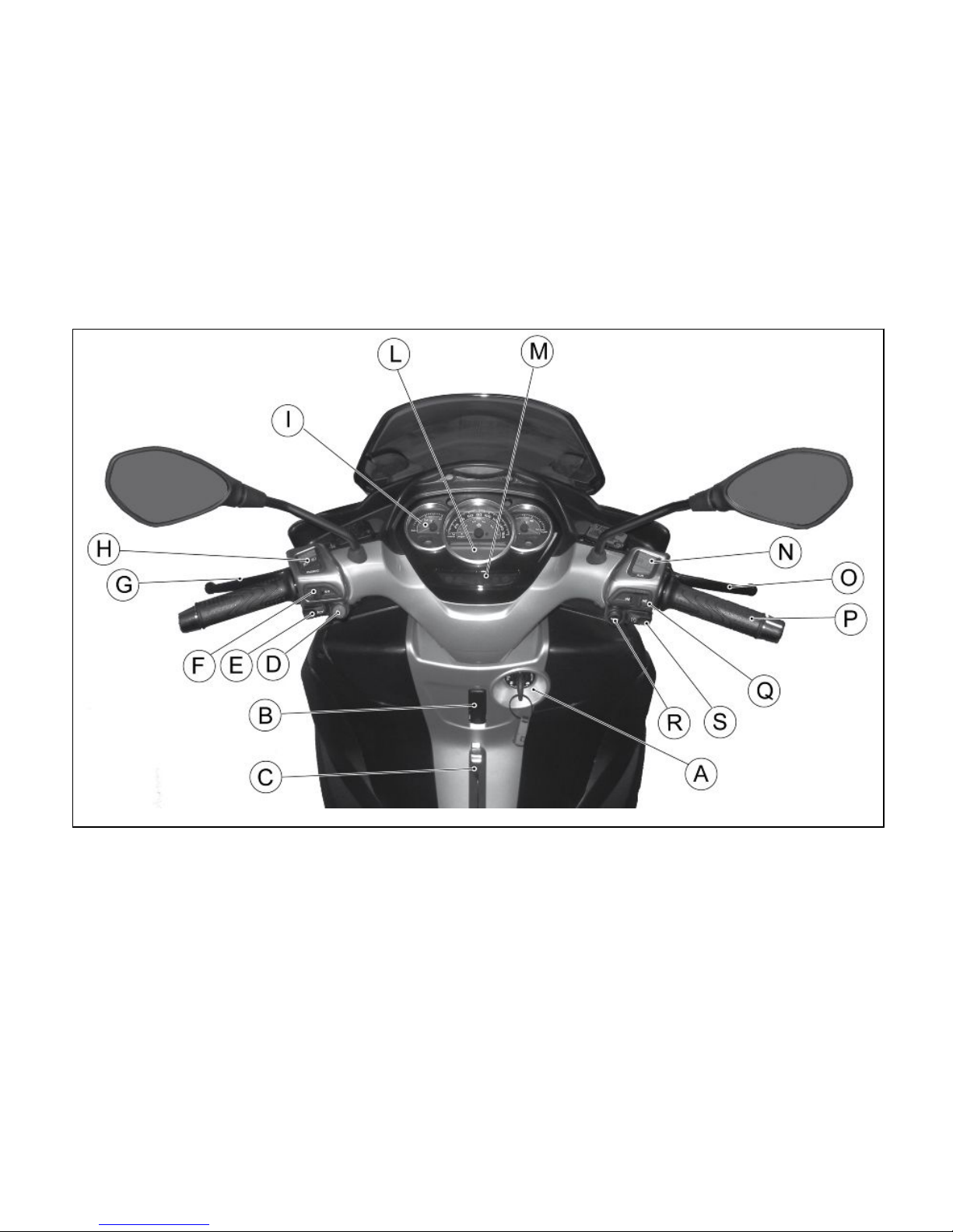
Dashboard (01_01)
A = Ignition key-switch
B = Bag hook
C = parking brake (where available)
D = Emergency turn indicator switch
E= Horn button
F = Turn signal switch
G = Rear brake lever
H = Light switch
I = Analogue instrument panel
L = Digital instrument panel
M = Warning light unit
N = Emergency cut-off switch RUN/OFF
O = Front brake lever
P = Throttle grip
Q = Front suspension locking-unlocking switch (if available)
R = Starter button
S = MODE button
9
1 Vehicle

01_02
10

Analogue instrument panel (01_02)
A = Immobilizer / anti-theft LED
B= Speedometer with twin scale (km/h and mph)
C = Fuel reserve warning light
D = Fuel gauge
E = Turn indicator warning light
F = High-beam warning light
G = Emergency turn indicator warning light
H = Warning light for parking brake engaged (where available)
I = Front suspension locking system warning light (where available)
L = Engine stop warning light
M = Front suspension locking system failure warning light (where available)
N = Digital display
O = Low oil pressure warning light
P = Engine control telltale light and injection system failure warning light
Q = Coolant temperature gauge
11
1 Vehicle

01_03
01_04
01_05
Clock (01_03, 01_04, 01_05, 01_06)
Use the switch "MODE" to "ODO" mode
Hold the switch "MODE" for more than 3 seconds, the hours will be displayed. Hours
will increase each time the "MODE" button is pressed.
Once the hour is adjusted, hold the switch "MODE" more than 3 seconds to display
the minutes. Minutes will increase each time the "MODE" button is pressed.
If no key is pressed for 3 seconds, the system will leave the clock adjustment mode.
WARNING
FOR SAFETY REASONS, CLOCK ADJUSTMENT IS POSSIBLE EXCLUSIVELY
WITH VEHICLE SPEED EQUAL TO 0 Km/h.
12

01_06
01_07
Digital lcd display (01_07)
A = Clock - date
B = «SERVICE» icon
C = Kilometre-mile indicator
D = State of battery charge icon
E = Odometer indicator, partial odometer I and II, state of battery charge and cyclically
selectable ambient temperature with the «MODE» button
F = Ambient temperature indicator in degrees Celsius or Fahrenheit
G = Indicator «ODO», «ODO I» or «ODO II»
H = Low ambient temperature icon
13
1 Vehicle

01_08
Maintenance icons (01_08)
At vehicle ignition, immediately after the ignition check, if there are less than 300 km
to the next scheduled service, the corresponding icon flashes for 5 seconds. Once the
scheduled service mileage is reached, the icon remains lit until the execution of the
scheduled service.
01_09
*MODE* button (01_09, 01_10)
Pushing the MODE button «A» for less than a second displays the following sequence
of functions:
•
Total Odometer «ODO»
•
Partial Odometer «ODO I»
•
Partial Odometer «ODO II»
•
State of battery charge
•
Ambient temperature «°»
To reset the trip odometer, move «ODO I» or «ODO II» and press for more than three
seconds the button MODE «A».
01_10
UNIT OF MEASUREMENT SETTING
When using the function measuring the voltage of the battery, holding down the
MODE button for longer than 10 seconds will switch between reading in kilometres or
miles for the odometer. For the first 5 seconds the display will not give any signal, for
the next 5 seconds the message unit of measurement (Km or mi) currently in use will
blink at a frequency of one flash per second. If the button is released before 10 seconds
the measurement unit is not changed.
14

01_11
Key switch (01_11)
1. LOCK = Ignition disabled, extractable key, mechanical antitheft device enabled. The parking brake (where available) cannot be released when pressed
and cannot be pressed when released.
2. «OFF» = Ignition disabled, extractable key, mechanical antitheft device disabled and enabled/disabled parking brake (where available).
3. ON = Ready to start, non-extractable key, mechanical antitheft device disabled.
4. «SEAT COMPARTMENT OPENING» = Seat compartment opening position,
this position is reached by pressing the key from "OFF" or "ON" and turning
it anticlockwise.
5. «FUEL TANK COVER OPENING» = Fuel tank cover opening position. Press
the key when in "OFF" or "ON" and turn it clockwise.
01_12
Locking the steering wheel (01_12)
Turn the handlebar to the left (as far as it will go), turn the key to «LOCK» and remove
the key.
Releasing the steering wheel
Reinsert the key and turn it to «OFF».
15
1 Vehicle

CAUTION
DO NOT TURN THE KEY TO «LOCK» OR «KEY OFF» WHILE RIDING.
01_13
Switch direction indicators (01_13)
Move switch «F» to the left to indicate a left turn; move switch «F» to the right to
indicate a right turn. Push the central part of switch «F» to deactivate the turn indica-
tors.
01_14
Horn button (01_14)
Push the button «E» to sound the horn.
16

01_15
Light switch (01_15)
When the light switch «H» is set to «0», the low-beam light is on. When set to «1»,
the high-beam light is activated. If the light switch «H» is pressed when set to «2», the
high-beam light flashing is activated. The switch goes back to «0» automatically.
01_16
Emergency flashing light button (01_16)
It enables the activation of the four turn indicators simultaneously. The control «D»
can be enabled only with the key set to «ON», but once enabled, it keeps functioning
even if the key is set to «OFF» or «LOCK». To disable this function, simply turn the
ignition switch to «ON».
17
1 Vehicle

01_17
Start-up button (01_17)
To start the engine, pull either brake lever and then press the starter button «R».
The vehicle is equipped with special starter procedure management. The starter motor
remains active until the engine starts even if switch «R» is released.
Keep one of the two brakes operated (front or rear) so as to not interrupt the starter
procedure.
The throttle grip must remain in the minimum position, because any other position
inhibits the vehicle starter.
The starter motor will remain active for a maximum of 5 consecutive seconds.
WARNING
IF THE VEHICLE IS EQUIPPED WITH THE SUSPENSION LOCKING DEVICE, IT
WILL START, BUT WILL REMAIN (ALSO BY USING THE THROTTLE GRIP) IDLE
IF THE RIDER IS NOT SEATED ON THE SADDLE IN RIDING POSITION.
01_18
Engine stop button (01_18)
The engine can be started when the emergency stop switch «N» is set to «1» RUN;
if the emergency stop switch «N» is set to «0» OFF, the engine cannot be started or
it shuts off if already running.
18

01_19
Front suspension unlock-lock switch (01_19)
The «Q» switch engages and disengages the front suspension locking system (where
available).
As the topic is so complex, find the instructions for using this control in the Use chapter.
The immobilizer system
In order to enhance theft protection, the vehicle is equipped with a «PIAGGIO IMMOBILIZER » electronic engine locking device that is activated automatically when the
ignition switch is removed. Upon start-up, the «PIAGGIO IMMOBILIZER» system
checks the starter key, and only if this key is recognised will the Immobiliser system
allow the vehicle to be started.
01_20
Keys (01_20)
Two types of keys come with the vehicle:
Key «A» is the «MASTER» key. Only a single copy of this key is supplied, which is
necessary to program all your other keys and for your dealer to perform some maintenance operations. We therefore recommend that it be used only under exceptional
circumstances.
The ignition key «B» (single copy supplied) is used for normal operations for the starter.
19
1 Vehicle

WARNING
LOSING THE MASTER KEY PREVENTS ANY FURTHER REPAIR OF THE "PIAGGIO IMMOBILISER" SYSTEM AND OF THE ENGINE CONTROL UNIT.
WARNING
KEEP THE MASTER KEY IN A SAFE PLACE (NOT IN THE VEHICLE).
01_21
Immobilizer device enabled indicator led (01_21)
Activation of the "PIAGGIO IMMOBILIZER" system is signalled by a flashing «A»
indicator. In order to reduce battery discharge, the indicator LED turns off automatically
after 48 hours of uninterrupted functioning. Should the system fail, different LED flashing patterns will provide the Authorised Service Centre with information on the type
of fault detected.
Operation
Each time the ignition key «B» is removed while in the «OFF» or «LOCK» positions,
the protection system activates the engine lock. Turning the ignition key «B» to
«ON» disables the engine lock, provided that the safety system recognises the code
transmitted by the key. If the code is not recognised, turn the ignition key «B» first to
«OFF» and then back to «ON» again; if lock persists, try again using the «A» MASTER
key. If the engine cannot be started, contact an Authorised Service Centre, which
is provided with the electronic equipment required to detect and repair the system.
When the supplementary starter keys are required, remember that the all the keys,
whether new or existing, should be programmed.
20

Contact an Authorised Service Centre and bring the «A» MASTER key and all
«B» starter keys that you own.
The codes of starter keys not submitted for the new programming procedure are deleted from the memory. Any lost starter keys will therefore not be enabled to start the
engine.
WARNING
EACH KEY HAS ITS OWN AND UNIQUE CODE, WHICH MUST BE STORED IN
THE SYSTEM CONTROL UNIT MEMORY.
VIOLENT SHOCKS MAY AFFECT THE ELECTRONIC COMPONENTS OF THE
KEY.
SHOULD THE VEHICLE CHANGE OWNER, IT IS ABSOLUTELY NECESSARY
THAT THE NEW OWNER GET POSSESSION OF THE KEY WITH THE MASTER
GRIP (AS WELL AS ALL OTHER IGNITION KEYS).
Programming the immobilizer system (01_22)
Below is described the procedure to follow for programming the PIAGGIO IMMOBILIZER system and/or for storing other key codes. The programming procedure should
be carried out with the engine stop switch set to «RUN».
START PROCEDURE
Insert the «MASTER» key «A» into the ignition switch (in «OFF») and turn it to
«ON». After 1 - 3 seconds, turn the key to «OFF » again and pull it out.
INTERMEDIATE STAGE
21
1 Vehicle

After extracting the «MASTER» key «A», insert, within ten seconds, the key that is
going to be programmed «B» and turn it immediately to «ON». After 1-3 seconds, turn
the key to «OFF» again and pull it out. In this way, a maximum of 7 keys can be
programmed by repeating the above procedure and keeping the indicated times.
FINAL STAGE
After extracting the key to be programmed «B», insert the «MASTER» key «A» again
and turn it to «ON» (perform this operation within the 10 seconds following the extraction of the previous key). Leave it in this position for 1 to 3 seconds and return it
to «OFF».
01_22
CORRECT PROGRAMMING CHECK PHASE
Insert the «MASTER» key «A» disabling the transponder «C» (i.e., by tilting the key
cap by 90°), and turn the key to «ON». Perform the engine starter operation. Ensure
that the engine does not start. Insert the programmed key «B» and repeat the starter
operation. Check that engine starts.
WARNING
SHOULD YOU START THE ENGINE WITH THE MASTER KEY (WITH TRANSPONDER OFF) OR IN THE EVENT OF WRONG OPERATION DURING PROGRAMMING, REPEAT THE PROCEDURE FROM THE BEGINNING.
22

01_23
01_24
Accessing the fuel tank (01_23, 01_24)
To open the fuel tank cover, set the key to «OFF» or « ON», then press and turn it
clockwise.
01_25
Opening the saddle (01_25)
To open the seat to the positions with the ignition switch in OFF and ON, press the
key and rotate counter clockwise.
23
1 Vehicle
Identification (01_26, 01_27)
Identification registration numbers are made up of a prefix and a number, stamped on
the chassis and on the engine. These numbers must always be quoted when ordering
spare parts. We recommend checking that the chassis registration number stamped
on the vehicle corresponds with that on the vehicle documentation.
CAUTION
BE REMINDED THAT ALTERING IDENTIFICATION REGISTRATION NUMBERS
CAN LEAD TO SERIOUS PENAL SANCTIONS (IMPOUNDING OF THE VEHICLE,
ETC.).
01_26
Chassis number
To read the chassis number, open the lid to access the fuel tank and lift the rubber
recycling tank.
24

01_27
Engine number
The engine number «B» is stamped near the rear left shock absorber lower support.
01_28
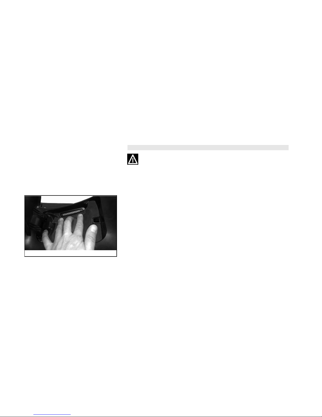
Bag clip (01_28)
To use the retractable bag hook «B» mounted on the leg shield back plate, pull it
slightly towards the back of the vehicle.
25
1 Vehicle

26
LUM MP3 300 YOURBAN RL-NRL
(2011)
Chap. 02
Use
27

Checks
Before using the vehicle, check:
1. That there is enough fuel in the fuel tank.
2. That the fluid level for front and rear brakes is correct.
3. That tyres are properly inflated.
4. The correct functioning of daylight running lights, headlamp, turn indicators, stop
light and license plate light.
5. The correct functioning of front and rear brakes.
6. The oil level in the gearcase.
7. Engine oil level.
8. The coolant level.
02_01
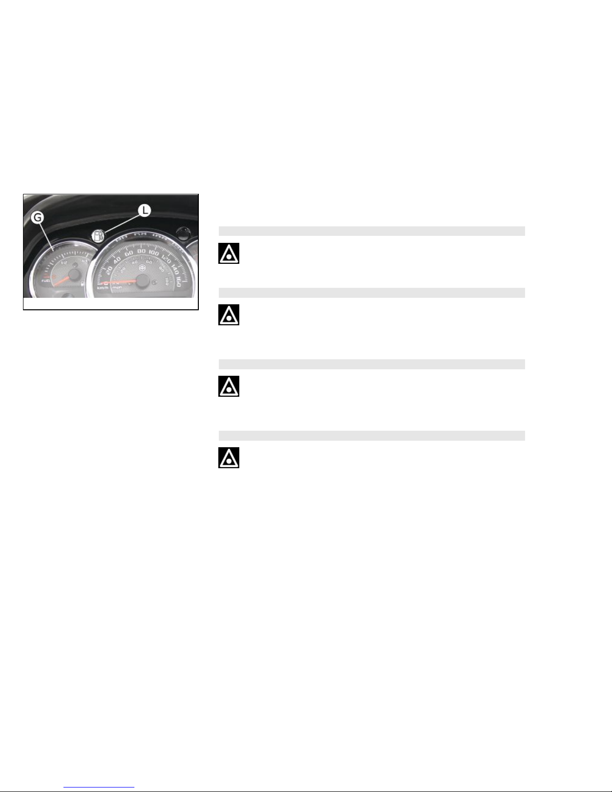
Refuelling (02_01, 02_02)
Fuel: Open the access door to the fuel tank cap and remove the cap «T».
Recommended fuel: Unleaded petrol, min octane rating of 95. The instrument «G»
indicates fuel level and the warning light «L» signals the reserve.
WARNING
SWITCH OFF THE ENGINE BEFORE REFUELLING WITH PETROL.
PETROL IS HIGHLY INFLAMMABLE.
DO NOT SMOKE AND KEEP NAKED FLAMES AT A DISTANCE:FIRE HAZARD.
DO NOT INHALE FUEL FUMES.
28
02_02
DO NOT ALLOW PETROL TO COME INTO CONTACT WITH HOT ENGINE OR
ANY PLASTIC PARTS.
CAUTION
PETROL DAMAGES THE PLASTIC PARTS OF THE BODYWORK.
WARNING
DO NOT RIDE WITH THE FUEL TANK ALMOST EMPTY, LACK OF FUEL CAN
DAMAGE THE CATALYTIC CONVERTER.
CAUTION
USING NON-RECOMMENDED PETROL REDUCES THE EFFICIENCY OF THE
EXHAUST AND FUEL SUPPLY SYSTEMS.
CAUTION
DO NOT USE THE VEHICLE TO THE COMPLETE EXHAUSTION OF THE FUEL;
SHOULD THIS OCCUR, DO NOT ATTEMPT TO START THE ENGINE. TURN THE
IGNITION SWITCH TO «OFF» AND TOP-UP THE TANK AS SOON AS POSSIBLE.
FAILURE TO FOLLOW THESE GUIDELINES COULD DAMAGE THE FUEL PUMP
AND/OR THE CATALYTIC CONVERTER.
29
2 Use
WARNING
IT IS HIGHLY INADVISABLE TO REFUEL USING METHODS OTHER THAN NORMAL FUEL PUMPS. IF PETROL IS NOT COMPLETELY CLEAN, IT CAN DAMAGE
THE FUEL SUPPLY SYSTEM FILTERS.
CAUTION
USING OILS OTHER THAN THOSE RECOMMENDED CAN SHORTEN THE LIFE
OF THE ENGINE.
Characteristic
Fuel tank (reserve)
11.0 (2l)
02_03
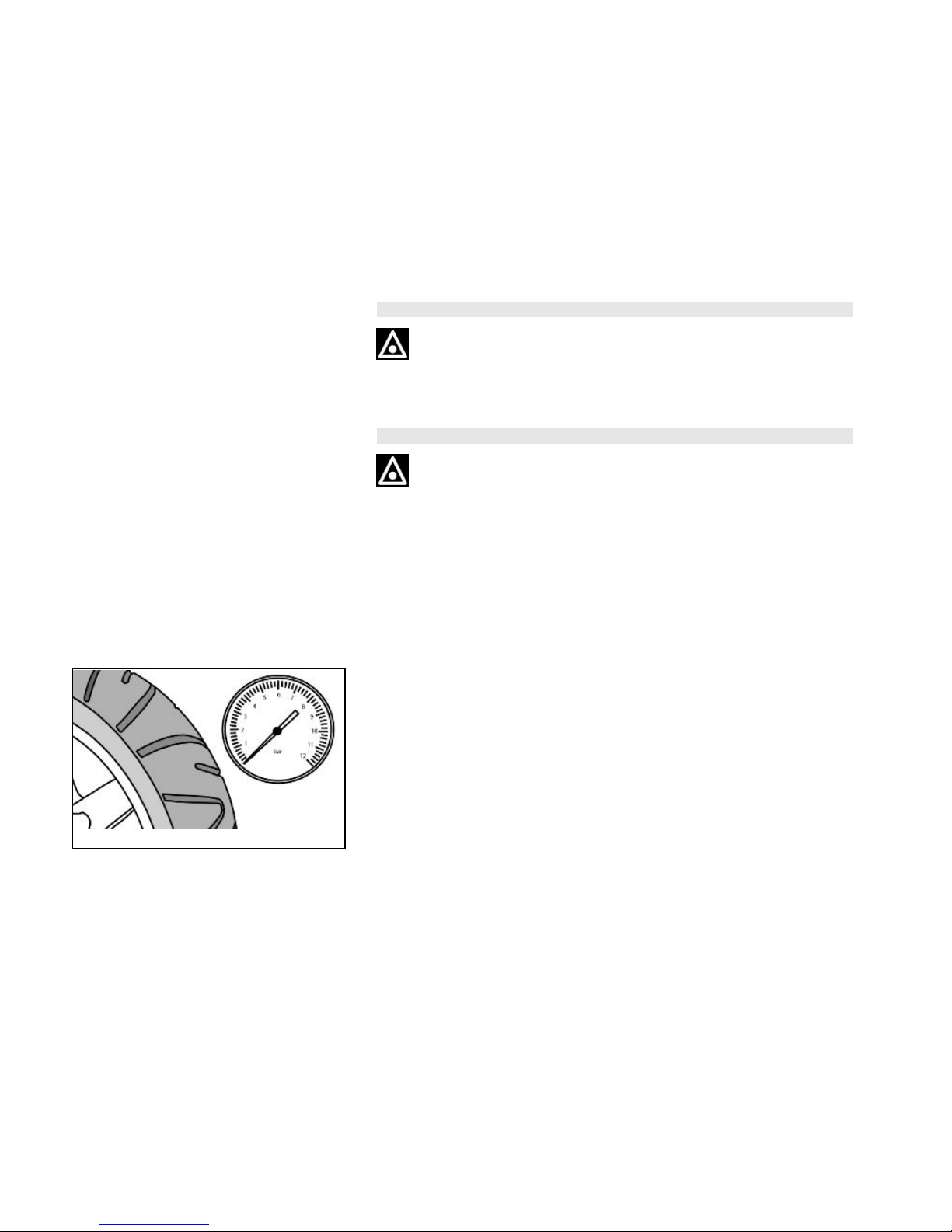
Tyre pressure (02_03)
Check tyre pressure and wear periodically (roughly every 500 km). Tyres feature wear
indicators; replace tyres as soon as these indicators become visible on the tyre tread.
Also check that the tyres do not show signs of splitting at the sides or irregular tread
wear; if this occurs go to an authorised workshop or at least to a workshop equipped
to replace tyres.
30
 Loading...