


X9 EVOLUTION

PIAGGIO WOULD LIKE TO THANK YOU
for choosing one of its products. We have prepared this booklet to help you to get the very best from your scooter. Please read it carefully before riding
the scooter for the first time. It contains information, tips and precautions for using your scooter. It also describes features, details and devices to assure
you that you have made the right choice. We believe that if you follow our suggestions, you will soon get to know your new vehicle and it will serve you
well for a long time to come. This booklet forms an integral part of the scooter; should the scooter be sold, it must be transferred to the new owner.
X9 Evolution 125 - 250
Downloaded from www.Manualslib.com manuals search engine

The instructions given in this manual are intended to provide a clear, simple guide to using your scooter; this booklet also details routine maintenance
procedures and regular checks that should be carried out on the vehicle at an authorised Dealer or Service Centre. The booklet also contains
instructions for simple repairs. Any operations not specifically described in this manual require the use of special tools and/or particular technical
knowledge: to carry out these operations refer to any authorised Dealer of Service Centres.
2
Downloaded from www.Manualslib.com manuals search engine
Personal safety
Failure to completely observe these instructions will result in serious risk of personal
injury.
Safeguarding the environment
Sections marked with this symbol indicate the correct use of the vehicle to prevent dam-
aging the environment.
Vehicle intactness
The incomplete or non-observance of these regulations leads to the risk of serious
damage to the vehicle and sometimes even the invalidity of the guarantee.
The signs that you see on this page are very important. They are used to highlight those
parts of the booklet that should be read with particular care. As you can see, each sign
consists of a different graphic symbol, making it quick and easy to locate the various
topics.
3
Downloaded from www.Manualslib.com manuals search engine

4
Downloaded from www.Manualslib.com manuals search engine

INDEX
VEHICLE...................................................................................... 7
Dashboard................................................................................ 8
Analogue instrument panel....................................................... 9
Instruments............................................................................... 9
Digital lcd display...................................................................... 10
Maintenance icons................................................................ 11
Setting the total and trip odometers...................................... 11
Setting the outside temperature display................................ 11
Kilometres/miles covered in reserve symbol......................... 12
Clock/date display................................................................. 13
Setting the hour/minutes function.......................................... 13
Setting the date function........................................................ 13
Setting the chronometer function.......................................... 14
Key switch................................................................................. 14
Locking the steering wheel.................................................... 14
Releasing the steering wheel................................................ 15
Switch direction indicators........................................................ 15
Horn button............................................................................... 16
Light switch............................................................................... 16
Emergency flashing light button................................................ 17
Start-up button.......................................................................... 17
Engine stop button.................................................................... 18
The immobilizer system............................................................ 18
Keys...................................................................................... 18
Immobilizerdevice enabled indicator led............................... 19
Operation............................................................................... 20
Programming the immobilizer system................................... 20
Accessing the fuel tank............................................................. 22
Power supply socket................................................................. 22
The saddle................................................................................ 23
Opening the saddle............................................................... 25
Identification.............................................................................. 26
USE.............................................................................................. 27
Checks...................................................................................... 28
Refuelling.................................................................................. 28
Shock absorbers adjustment.................................................... 29
Running in................................................................................. 30
Starting up the engine............................................................... 31
Precautions........................................................................... 32
Difficult start up......................................................................... 33
Stopping the engine.................................................................. 33
Stand......................................................................................... 34
Automatic transmission............................................................. 35
Safe driving............................................................................... 36
MAINTENANCE........................................................................... 39
Engine oil level.......................................................................... 40
Engine oil level check............................................................ 40
Engine oil top-up................................................................... 40
Warning light (insufficient oil pressure)................................. 41
Engine oil change.................................................................. 41
Hub oil level.............................................................................. 43
Tyres......................................................................................... 44
Spark plug dismantlement........................................................ 45
Removing the sides.................................................................. 47
Removing the air filter............................................................... 48
Air filter cleaning....................................................................... 49
Secondary air system............................................................... 49
Cooling fluid level...................................................................... 50
Checking the brake oil level...................................................... 52
Braking system fluid top up................................................... 53
Battery....................................................................................... 54
Use of a new battery............................................................. 55
Checking the electrolyte level................................................ 55
Long periods of inactivity.......................................................... 56
Fuses........................................................................................ 57
Front light group........................................................................ 62
5
Downloaded from www.Manualslib.com manuals search engine

Headlight adjustment............................................................. 64
Front direction indicators........................................................... 64
Rear optical unit........................................................................ 65
Number plate light..................................................................... 66
Helmet compartment lighting bulb............................................ 66
Brake light................................................................................. 66
Rear-view mirrors...................................................................... 67
Idle adjustment.......................................................................... 67
Front and rear disc brake.......................................................... 68
Puncture.................................................................................... 69
Periods of inactivity................................................................... 70
Cleaning the vehicle.................................................................. 71
TECHNICAL DATA...................................................................... 75
Kit equipment............................................................................ 80
SPARE PARTS AND ACCESSORIES........................................ 81
Warnings................................................................................... 82
PROGRAMMED MAINTENANCE............................................... 85
Scheduled maintenance table................................................... 86
6
Downloaded from www.Manualslib.com manuals search engine

X9 Evolution
125 - 250
Chap. 01
Vehicle
7
Downloaded from www.Manualslib.com manuals search engine
01_01
01_02
01_03
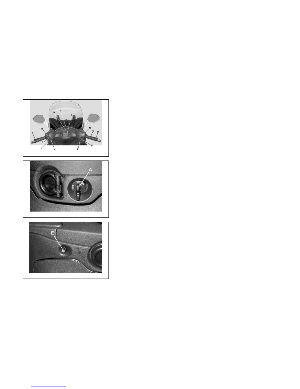
Dashboard (01_01, 01_02, 01_03)
A = Key switch
B = Start-up button
C = Accelerator control
D = Front brake control
E = Saddle electric opening button
F = Digital instrument panel
G = Direction indicator switch
H = Light switch
I = Combined braking control (front and rear)
L = Horn button
M = Engine lock RUN-OFF switch
N = Emergency flashing light start button (4 direction indicators)
O = Indicator unir
P = Button fitting
R = Analogue instrument unit
8
Downloaded from www.Manualslib.com manuals search engine
01_04
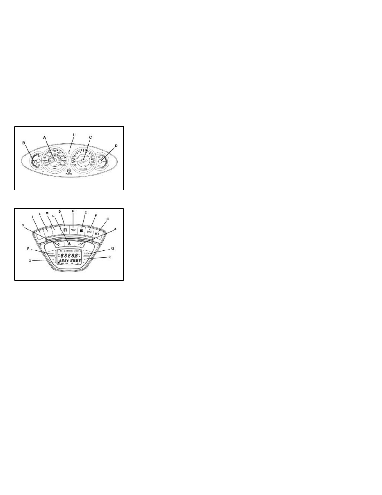
Analogue instrument panel (01_04)
A = Tachometer
B = Fuel level indicator
C = Rpm counter
D = Cooling fluid temperature indicator
U = Alarm led
01_05
Instruments (01_05)
A = RH direction indicator
B = LH direction indicator
C = Emergency flashing light indicator (4 direction indicators)
D = RUN-OFF (engine stop)/side stand open indicator
E = Fuel reverse indicator
F = Light indicator
G = Upper beam indicator
H = Low oil pressure indicator
I = Fitting for indicator light
L = Fitting for indicator light
M = Fitting for indicator light
N = LCD display
O = "Mode" button
9
1 Vehicle
Downloaded from www.Manualslib.com manuals search engine
P = "Trip" button
Q = "Clock" button
R = "Set" button
01_06
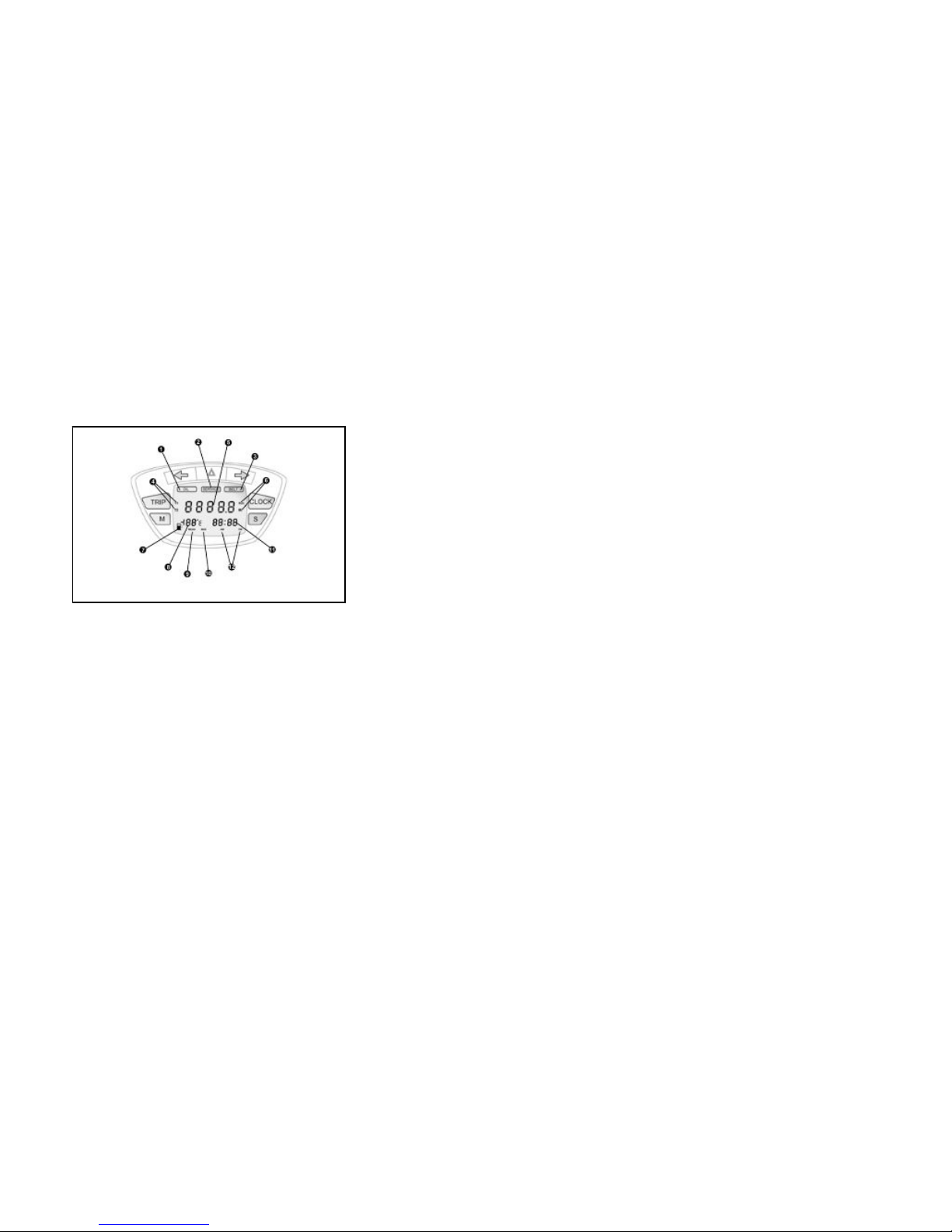
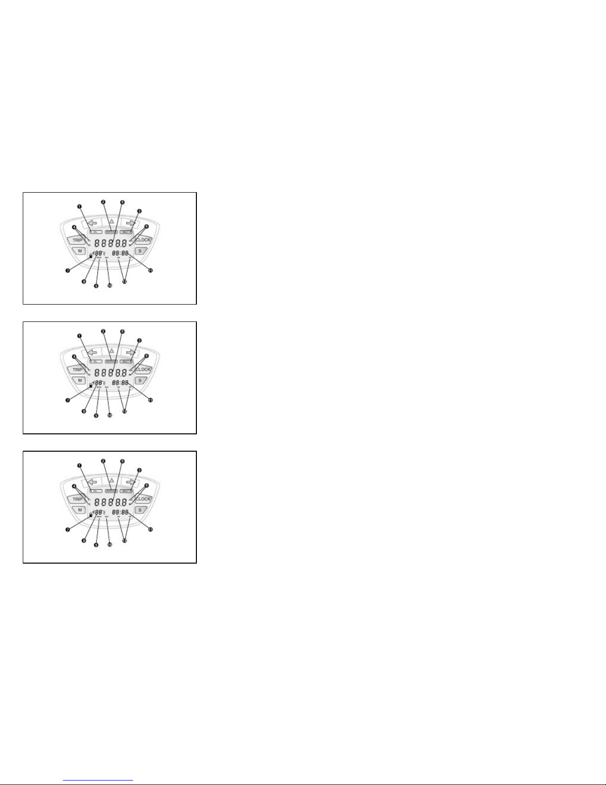
Digital lcd display (01_06)
1 = Maintenance icon «OIL»;
2 = Maintenance icon «SERVICE»;
3 = Maintenance icon «BELT»;
4 = Trip odometer display symbols «T1» or «T2»;
5 = Five-digit display for kilometres/miles covered;
6 = Display mode symbols «Km» or «Mi»;
7 = Kilometres/miles covered in reserve symbol;
8 = 2-digit display with symbols «-» temperature display, mean speed, maximum
speed; kilometres/mph covered in reserve;
9 = Mean speed mode display symbol «MEAN»;
10 = Maximum speed mode display symbol «MAX»;
11 = 4-digit display of clock, chronometer and date functions;
12 = Time indication symbols «AM» or «PM»
10
Downloaded from www.Manualslib.com manuals search engine

01_07
Maintenance icons (01_07)
The icons warn the user when the scheduled maintenance interventions are required.
The «OIL» icon flashes when 1,000 Km are reached, after that every 3,000 Km. The
«SERVICE» icon flashes the first time at 1,000 Km or after 1 year, after that every
6,000 Km or after 1 year. The «BELT» icon flashes every 12,000 Km.
WARNING
REFER TO THE «SCHEDULED MAINTENANCE TABLE» FOR FURTHER MAIN-
TENANCE OPERATIONS
01_08
Setting the total and trip odometers (01_08)
The «TRIP» button displays partial distances «T1» and «T2» and the total distance,
if pressed repeatedly for less than 1 second.
Press it for over 3 seconds to reset the trip odometer. Press «TRIP» again to return
to the total odometer «5».
01_09
Setting the outside temperature display (01_09)
The temperature value «8» updates automatically at every variation of ± 1 °C. When
the external temperature reaches +3 °C, the display flashes for 40 seconds; the same
occurs at every decrease of temperature.
Press «M» to display the mean speed, identified by symbol «MEAN», which updates
automatically every 30 seconds even if the key is set to «OFF». Press «M» to display
the maximum speed reached by the vehicle and identified by the symbol «MAX»,
press again to display the kilometres traveled in reserve; the value is stored also with
key set to «OFF». Press «M» again to return to the outside temperature display. Keep
11
1 Vehicle
Downloaded from www.Manualslib.com manuals search engine

«M» pressed for more than 3 seconds to reset the selected function, except the tem-
perature.
WARNING
WARNING
THE FLASHING FUNCTION WHEN A TEMPERATURE OF +3 °C AND LESS IS
REACHED HAS PRIORITY ON THE MEAN AND MAX SPEED INDICATION, SO IT
IS AUTOMATICALLY DISPLAYED. HOWEVER, YOU CAN PRESS BUTTON «M»
TO DISPLAY THE SPEED AND DISTANCE COVERED IN RESERVE VALUES.
01_10
01_11
Kilometres/miles covered in reserve symbol (01_10, 01_11)
The symbol is automatically displayed when the fuel reserve light indicator «E» turns
on, along with indicator «8» of the kilometres/mph covered in reserve. This function
has the utmost priority over the previous three ones, so when the vehicle is in reserve,
icon «7» is automatically displayed along with the kilometres being covered in reserve
are displayed. Press «M» to return to the other information.
12
Downloaded from www.Manualslib.com manuals search engine
01_12
Clock/date display (01_12)
Press «CLOCK» to display the date (day/month). Press «CLOCK» to display the
chronometer.
Press «CLOCK» to return to the clock display «12».
01_13
Setting the hour/minutes function (01_13)
Press «CLOCK» for more than 3 seconds and set the time by button «S». Wait until
the minutes begin flashing and set by button «S». Wait approx. 8 seconds or press
«CLOCK» to return to the updated hours/minutes function.
01_14
Setting the date function (01_14)
Press «CLOCK» for more than 3 seconds and set the day by button «S». Wait until
the month begins flashing and set by button «S». Wait until the year begins flashing
and set by button «S». Wait approx. 3 seconds or press «CLOCK» to return to the
date function.
13
1 Vehicle
Downloaded from www.Manualslib.com manuals search engine

01_15
Setting the chronometer function (01_15)
Press «S» to enable and stop the chronometer. Press «CLOCK» and «S» together
to reset the chronometer.
CAUTION
IT IS STRONGLY ADVISED NOT TO USE THE FUNCTIONS OF THE DIGITAL
DISPLAY PANEL WHILE THE VEHICLE IS MOVING.
01_16
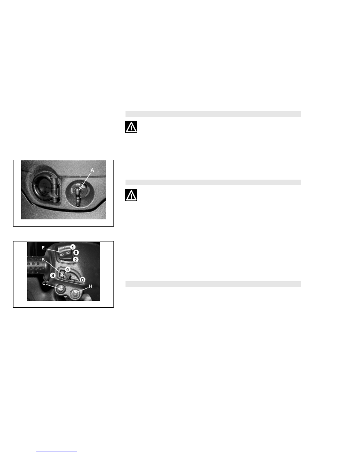
Key switch (01_16)
LOCK= Ignition barred, key can be removed, mechanical antitheft device activated.
OFF= Ignition barred, key can be removed, mechanical antitheft device deactivated.
ON= Prestarting position, key cannot be removed, mechanical antitheft device deac-
tivated.
Locking the steering wheel
Turn the handlebar to the left (as far as it will go), turn the key to «LOCK» and remove
the key.
14
Downloaded from www.Manualslib.com manuals search engine
CAUTION
DO NOT TURN THE KEY TO «LOCK» OR «OFF» WHILE RIDING.
01_17
Releasing the steering wheel (01_17)
Reinsert the key and turn it to «OFF».
CAUTION
DO NOT TURN THE KEY TO «LOCK» OR «OFF» WHILE RIDING.
01_18
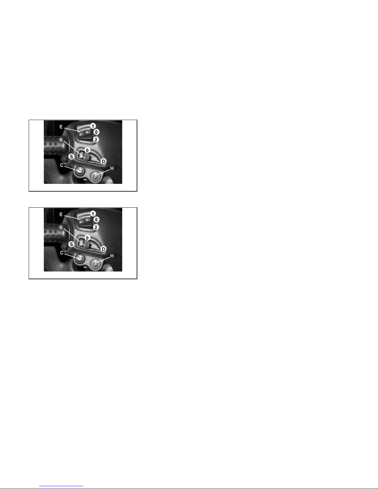
Switch direction indicators (01_18)
Lever to «S» = left direction indicators on;
Lever to «D» = right direction indicators on;
The lever automatically returns to position «0» and the indicators «B» remain on; press
the lever to turn them off.
WARNING
WARNING
THE ONBOARD COMPUTER DISABLES THE FLASHING LIGHTS AFTER 1 KM.
15
1 Vehicle
Downloaded from www.Manualslib.com manuals search engine
01_19
Horn button (01_19)
Push the «C» button to sound the horn.
01_20
Light switch (01_20)
0 = Low-beam light
1 = High beam light
2 = Passing (flashing)
16
Downloaded from www.Manualslib.com manuals search engine

01_21
Emergency flashing light button (01_21)
It starts the 4 direction indicators at the same time. The control «H» can only be en-
abled with key set to «ON», but once it has been enabled it remains on with key set
to «OFF» and «LOCK» as well.
This function can only be disabled with key switch set to «ON».
01_22
Start-up button (01_22)
Starter button "G"
17
1 Vehicle
Downloaded from www.Manualslib.com manuals search engine

01_23
Engine stop button (01_23)
0 = OFF
1 = RUN
The immobilizer system
In order to enhance theft protection, the scooter is equipped with a «PIAGGIO IM-
MOBILIZER » electronic engine locking device that is activated automatically when
the starter key is removed. Upon start-up, the «PIAGGIO IMMOBILIZER» system
checks the starter key, and only if this key is recognised will the immobilizer system
allow the scooter to be started.
01_24
Keys (01_24, 01_25, 01_26)
Two types of keys come with the vehicle. The red-handgrip key "A" is the "MAS-
TER" key. Only a single copy of this key is supplied, which is necessary to program
all your other keys and for your dealer to perform some maintenance operations. For
this reason it is advised that it be used only in exceptional circumstances. The black
key "B" (single copy supplied) is used for normal operations such as:
- engine start up
- glove-box opening
Together with the keys comes a CODE CARD which is imprinted with the mechanical
code of the keys.
18
Downloaded from www.Manualslib.com manuals search engine

01_25
01_26
WARNING
LOSING THE RED KEY PREVENTS ANY REPAIRS OF THE 'PIAGGIO IMMOBIL-
IZER' SYSTEM AND THE ENGINE CONTROL UNIT.
WARNING
KEEP THE 'CODE CARD' AND THE RED HANDGRIP KEY IN A SAFE PLACE (NOT
ON YOUR VEHICLE).
01_27
Immobilizerdevice enabled indicator led (01_27)
The enabling of the «PIAGGIO IMMOBILIZER» system is indicated by the flashing of
a special led «U», (see «Analogue instrument panel»).
To prevent discharging the battery, the led automatically turns off after about 48 hours
of continuous operation.
In the event of system failure, the indicator led informs the Authorised Piaggio Serv-
ice Centre of the nature of the failure, based on the type of flashes emitted.
19
1 Vehicle
Downloaded from www.Manualslib.com manuals search engine

Operation
Every time the starter key is removed in the "OFF" or "LOCK" position, the safety
system activates the immobilizer system. Turning the key to "ON" disables the engine
lock, provided that the safety system recognises the code transmitted by the key. If
the code is not recognised, turn the key first to "OFF" and then to "ON"; if the lock
cannot be disabled, try with the other key supplied (red-coloured). If the engine cannot
be started, contact an Authorised Piaggio Service Centre, which is provided with
the electronic equipment required to detect and repair the system. The immobiliser is
also activated in the engine is switched off with the RUN OFF switch. This happens
even if the starter key is in position "ON".
When additional keys are required, please note that data storage (up to 3 keys max.)
must be done on all keys, both new ones and existing ones. Take the key with the red
grip and all the black keys supplied to an Authorised Piaggio Service Centre. The
codes of keys not submitted for the new storage procedure are deleted from the
memory. Any lost keys will therefore not be enabled to start the engine.
WARNING
EACH KEY HAS ITS OWN AND UNIQUE CODE, WHICH MUST BE STORED BY
THE SYSTEM CONTROL UNIT.
VIOLENT SHOCKS MAY AFFECT THE ELECTRONIC COMPONENTS OF THE
KEY.
IF OWNERSHIP OF THE VEHICLE IS TRANSFERRED, THE RED-HANDGRIP KEY
(AS WELL AS THE OTHER KEYS) AND THE "CODE CARD" MUST ALSO BE
TRANSFERRED TO THE NEW OWNER.
Programming the immobilizer system
In the following is described the procedure to follow to program the "PIAGGIO IM-
MOBILIZER" system and/or enter other keys in the memory.
20
Downloaded from www.Manualslib.com manuals search engine

Procedure start - red key
Insert the red-handgrip key in the switch key (in "OFF" position) and turn it to "ON".
After 1 - 3 seconds, turn the key to "OFF" again and pull it out.
Intermediate step - black key
After pulling out the red key, insert the black key within 10 seconds and promptly turn
it to "ON". After 1-3 seconds, turn the key to "OFF" again and pull it out. In this way,
a maximum of 3 black keys can be programmed by repeating the above procedure
keeping the indicated times.
Final step - red key
After pulling out the last black key, insert the red key again and turn it to "ON" (this
operation should be performed within 10 seconds of pulling out the previous key).
Leave it in this position for 1 to 3 seconds and return it to the «OFF» position.
Proper programming check
Insert the red key disabling the transponder (i.e., tilt the key cap by 90°) and turn the
key to "ON". Perform the engine start-up operation. Ensure that the engine does not
start. Insert the black key and repeat the start-up operation. Check that engine starts.
WARNING
SHOULD THE ENGINE START WITH THE RED KEY (WITH TRANSPONDER OFF),
OR IN THE EVENT OF WRONG OPERATION DURING PROGRAMMING, REPEAT
THE PROCEDURE FROM THE BEGINNING.
21
1 Vehicle
Downloaded from www.Manualslib.com manuals search engine

01_28
01_29
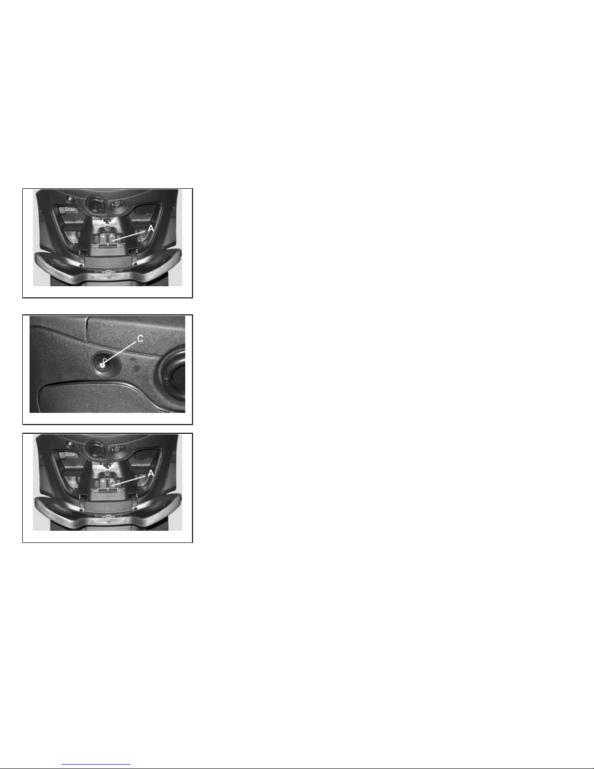
Accessing the fuel tank (01_28, 01_29)
Insert the key into the switch and press down until the glove box opens. In the event
that the key switch is in «LOCK», turn the key to «OFF» or «ON» before pressing
down. Press lever «B» and open the cover over the fuel tank cap «C».
01_30
Power supply socket (01_30)
There is a plug socket "D" inside the helmet compartment.
The plug socket may be used for external consumers (mobile phone, inspection light,
etc.).
22
Downloaded from www.Manualslib.com manuals search engine

CAUTION
PROLONGED USE OF THE PLUG SOCKET MAY RESULT IN PARTIAL DIS-
CHARGE OF THE BATTERY
Electric characteristic
Plug socket
12 V - 180 W MAX
Maximum power
180 W
01_31
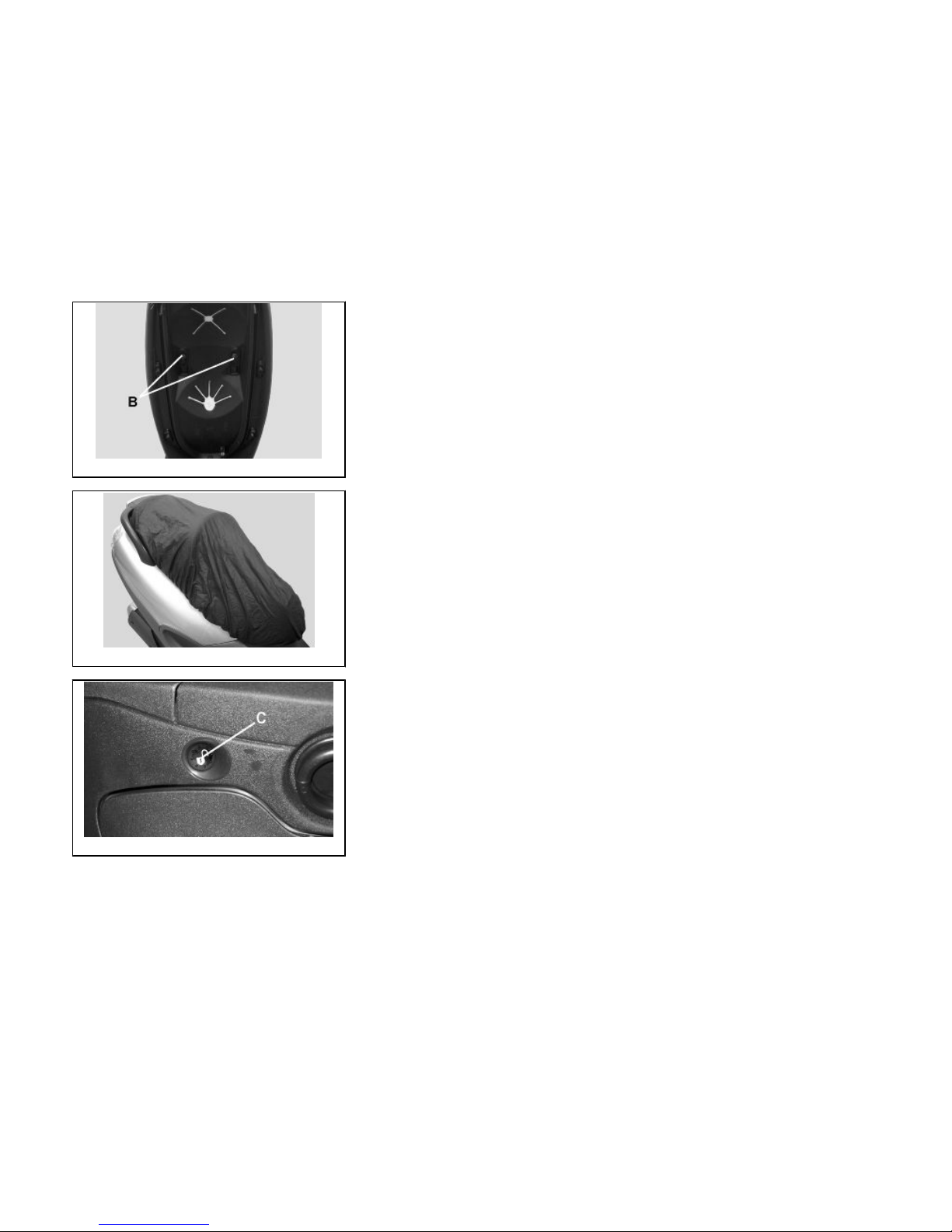
The saddle (01_31, 01_32, 01_33, 01_34, 01_35)
The saddle is provided with a back that can be moved forward or backward for your
comfort. To move the back, raise the saddle by button «C» or push lever «A», and
adjust the position of screws «B». The saddle is provided with a protective covering
that may be used, for example, in case of rain. To use the covering, raise the saddle
and pull it out. Fit it onto the saddle without pulling too much to prevent breakage, then
close the saddle.
CAUTION
DO NOT USE THE VEHICLE WITHOUT THE PROTECTION COVER.
23
1 Vehicle
Downloaded from www.Manualslib.com manuals search engine
01_32
01_33
01_34
24
Downloaded from www.Manualslib.com manuals search engine
01_35
01_36
01_37
Opening the saddle (01_36, 01_37)
With the key set to «OFF» or «ON», or with engine on, it is possible to electrically open
the saddle by pressing button «C». If the electric opening does not work, use the
emergency lever "A". When the key is set to «LOCK» the saddle cannot be opened.
25
1 Vehicle
Downloaded from www.Manualslib.com manuals search engine
01_38
01_39
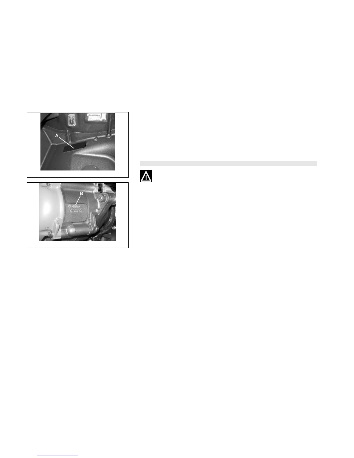
Identification (01_38, 01_39)
The identification registration numbers consist of a prefix stamped on the chassis and
engine "B" respectively, followed by a number. These numbers must always be indi-
cated on spare parts requests. To read the chassis number, remove the relevant port
"A" in the helmet compartment placed under mat. We recommend checking that the
chassis registration number stamped on the scooter corresponds with that on the
scooter's documents.
CAUTION
BE REMINDED THAT ALTERING IDENTIFICATION REGISTRATION NUMBERS
CAN LEAD TO SERIOUS PENAL SANCTIONS (IMPOUNDING OF THE VEHICLE,
ETC.).
26
Downloaded from www.Manualslib.com manuals search engine

X9 Evolution
125 - 250
Chap. 02
Use
27
Downloaded from www.Manualslib.com manuals search engine
Checks
Before using the vehicle, check:
1. That the fuel tank is full.
2. Front and rear brake fluid level
3. That the tyres are properly inflated.
4. The functioning of the tail lights, the headlight, and the turn indicators.
5. The functioning of the front and rear brakes.
6. The oil level in the gearcase.
7. The engine oil level.
8. The coolant level.
02_01
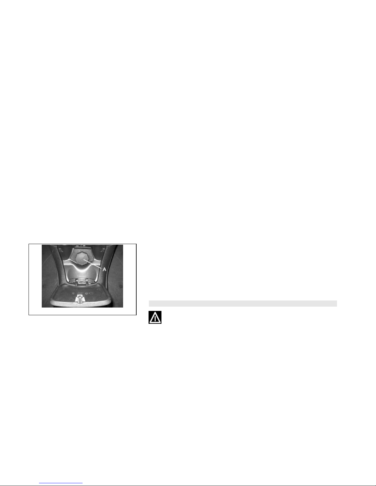
Refuelling (02_01, 02_02)
Fuel: Open the flap as described in the section "Access to the fuel tank" and unscrew
the cap "A".
Recommended fuel:
Unleaded petrol, min octane rating of 95.
Fuel level is indicated on the digital instrument panel «B».
WARNING
SWITCH OFF THE ENGINE BEFORE REFUELLING WITH PETROL.
PETROL IS HIGHLY INFLAMMABLE.
DO NOT SMOKE AND KEEP OPEN FLAMES AT A DISTANCE:FIRE HAZARD.
28
Downloaded from www.Manualslib.com manuals search engine

02_02
DO NOT INHALE FUEL FUMES.
DO NOT ALLOW PETROL TO COME INTO CONTACT WITH HOT ENGINE OR
ANY PLASTIC PARTS.
CAUTION
PETROL DAMAGES THE PLASTIC PARTS OF THE BODYWORK.
Characteristic
Fuel tank capacity
14,5 l (approx.)
Reserve
2.5 l
02_03
Shock absorbers adjustment (02_03)
The preloading of the springs can be adjusted to 4 positions using the ring nut located
in the lower part of the shock absorbers and the specific spanner supplied.
Position 1: minimum preload: driver only
Position 2 medium preloading: driver only
Position 3 medium preloading: rider and passenger
Position 4: maximum preloading: driver, passenger, and luggage.
In order to carry out this operation you will need to use the specific spanner in the kit.
29
2 Use
Downloaded from www.Manualslib.com manuals search engine

CAUTION
RIDING THE VEHICLE WITH THE SPRING PRELOADING NOT CORRECTLY SET
FOR THE RIDER AND POSSIBLE PASSENGER, COULD REDUCE THE COM-
FORT OF THE RIDE AND THE PRECISION OF THE STEERING.
WARNING
WE RECOMMEND WEARING GLOVES WHILE CARRYING OUT THIS OPERA-
TION IN ORDER TO AVOID INJURIES.
WARNING
WE STRONGLY RECOMMEND NOT TO ADJUST BOTH SHOCK ABSORBERS
WITH DIFFERENT PRELOADING
02_04
Running in (02_04)
WARNING
DURING THE FIRST 1000 KM DO NOT RIDE THE VEHICLE OVER 80% OF ITS
MAXIMUM SPEED. AVOID TWISTING THE THROTTLE GRIP FULLY OR KEEP-
ING A CONSTANT SPEED ALONG LONG SECTIONS OF ROAD. AFTER THE
FIRST 1000 KM, GRADUALLY INCREASE SPEED UNTIL REACHING THE MAX-
IMUM PERFORMANCE.
30
Downloaded from www.Manualslib.com manuals search engine
 Loading...