


Philips FW870C/22, FW870C/21, FW870C/19, FW870C/18, FW830C/34 User Manual
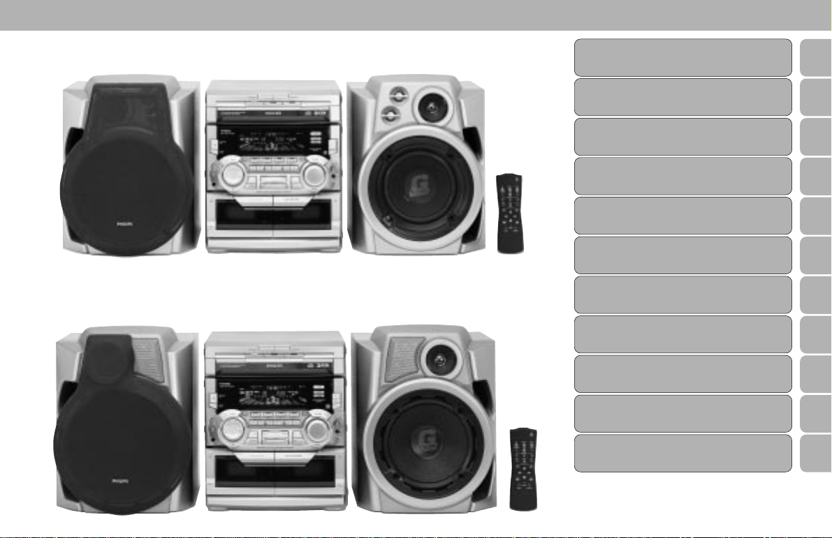
FW830C
FW870C
1
Important notes for users in the U.K.
CLASS 1
LASER PRODUCT
Mains plug
FrançaisEnglish
This apparatus is fitted with an approved 13 Amp plug. To change a
fuse in this type of plug proceed as follows:
1 Remove fuse cover and fuse.
Español
2 Fix new fuse which should be a BS1362 5 Amp, A.S.T.A. or BSI
approved type.
3 Refit the fuse cover.
Deutsch ∂ППЛУИО¿PortuguêsSuomiDanskSvenskaItalianoNederlands
If the fitted plug is not suitable for your socket outlets, it should be
cut off and an appropriate plug fitted in its place.
If the mains plug contains a fuse, this should have a value of 5
Amp. If a plug without a fuse is used, the fuse at the distribution
board should not be greater than 5 Amp.
Note: The severed plug must be disposed of to avoid a possible
shock hazard should it be inserted into a 13 Amp socket elsewhere.
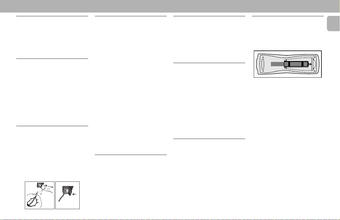
How to connect a plug
The wires in the mains lead are coloured with the following code:
blue = neutral (N), brown = live (L).
As these colours may not correspond with the colour markings
identifying the terminals in your plug, proceed as follows:
• Connect the blue wire to the terminal marked N or coloured
black.
• Connect the brown wire to the terminal marked L or coloured
red.
• Do not connect either wire to the earth terminal in the plug,
marked E (or e) or coloured green (or green and yellow).
Before replacing the plug cover, make certain that the cord grip is
clamped over the sheath of the lead - not simply over the two
wires.
Copyright in the U.K.
Recording and playback of material may require consent. See
Copyright Act 1956 and The Performer’s Protection Acts 1958 to
1972.
2
Italia
DICHIARAZIONE DI CONFORMITA’
Si dichiara che l’apparecchio FW830C e
FW870C Philips risponde alle prescrizioni
dell’art. 2 comma 1 del D.M. 28 Agosto 1995
n. 548.
Fatto a Eindhoven , il 30/2/1999
Philips Consumer Electronics
Philips, Glaslaan 2
5616 JB Eindhoven, The Netherlands
Norge
Typeskilt finnes på apparatens underside.
Observer:
Den innebygde netdelen er derfor ikke frakoplet
nettet så lenge apparatet er tilsluttet
nettkontakten.
For å redusere faren for brann eller elektrisk
støt, skal apparatet ikke utsettes for regn eller
fuktighet.
Nettbryteren er sekundert innkoplet.
INDEX
FW830C
FW870C
English .....................................4
Français .................................27
Español ..................................51
Deutsch..................................75
Nederlands..........................101
Italiano.................................125
Svenska ...............................149
Dansk ...................................171
Suomi ...................................195
Português ............................217
∂ППЛУИО¿
............................ 241
EnglishFrançais
Español
NederlandsItalianoSvenskaDanskSuomiPortuguês∂ППЛУИО¿ Deutsch
3

English
4
CONTENTS GENERAL INFORMATION SAFETY INFORMATION
General Information ........................ 5
Safety Information ........................... 5
Preparation ................................. 6 - 7
Controls ..................................... 8 - 10
Operating The System ...........11 - 13
CD ............................................. 14 - 16
Tuner .........................................17 - 18
Tape...........................................19 - 20
Aux ...................................................20
Karaoke ...........................................20
Recording.................................21 - 22
Clock ................................................ 23
Timer ................................................ 23
Sleep Timer.................................... 24
Maintenance .................................. 24
Specifications ................................ 25
Troubleshooting............................. 26
General Information
• The typeplate (which contains the
serial number) is located at the rear
of the system.
• Recording is permissible if
copyright or other rights of third
parties are not infringed.
• This product complies with the
radio interference requirements of
the European Community.
Environmental Information
All unnecessary packaging has been
omitted. We have tried to make the
packaging easy to separate into three
materials: cardboard (box), polystyrene
foam (buffer) and polyethylene (bags,
protective foam sheet).
Your system consists of materials which
can be recycled and reused if disassembled
by a specialized company. Please observe
the local regulations regarding the disposal
of packaging materials, exhausted
batteries and old equipment.
Acknowledgement
The Dolby B NR System and the double-D
symbol d are trademarks of Dolby
Laboratories Licensing Corporation.
Manufactured under license from Dolby
Laboratories Licensing Corporation.
Accessories
– Remote control
– Batteries (two AA size) for remote
control
– AM loop antenna
– FM wire antenna
– AC power cord
(Supplied)
Safety Information
• Before operating the system, check that
the operating voltage indicated on the
typeplate (or the voltage indication
beside the voltage selector) of your
system is identical with the voltage of
your local power supply. If not, please
consult your dealer. The typeplate is
located at the rear of your system.
• When the system is switched on, do not
move it around.
• Place the system on a solid base (e.g. a
cabinet).
• Place the system in a location with
adequate ventilation to prevent internal
heat build-up in your system.
• The system incorporates a built-in
safety feature that prevents over
heating.
• Do not expose the system to excessive
moisture, rain, sand or heat sources.
• Under no circumstances should you
repair the system yourself, as this will
invalidate the warranty!
• If the system is brought directly from a
cold to a warm location, or is placed in a
very damp room, moisture may
condense on the lens of the CD unit
inside the system. Should this occur, the
CD player will not operate normally.
Leave the power on for about one hour
with no disc in the system until normal
playback is possible.
• Electrostatic discharge may cause
unexpected problems. See whether
these problems disappear if you unplug
the AC power cord and plug it in again
after a few seconds.
• To disconnect the system from the
power supply completely, remove
the AC power plug from the wall
socket.
English
5
PREPARATION
English
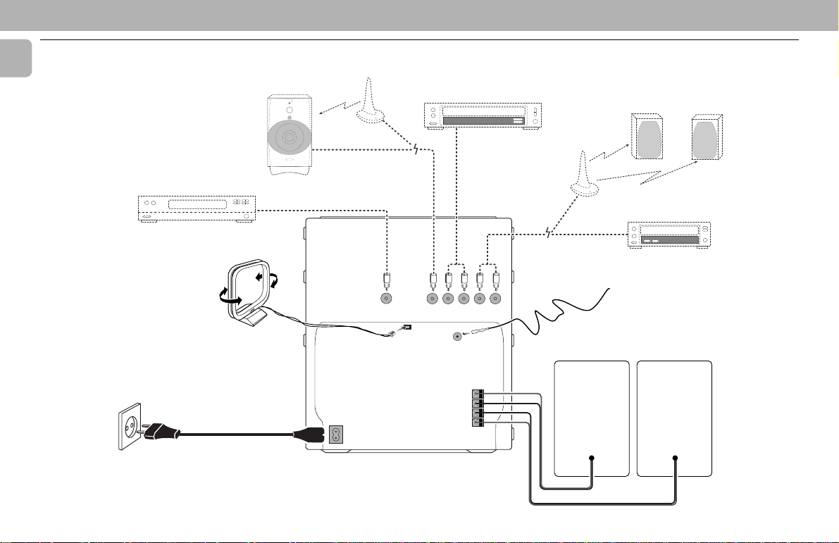
Rear Connections
G
STANDBY ON
E
V
L
E
R
L
E
F
C
O
O
N
O
T
W
R
B
O
U
L
S
MIN MAX
CUT OFF FREQUENCY
HIGH POWER SUBWOOFER
60Hz 150Hz
F
AUDIO OUT
E
D
AUDIO IN
LRLR
A
MAINS
DIGITAL
OUT
AC
~
AM ANTENNA
SUB-
WOOFER
OUT
AUX IN
FM ANTENNA 75Ω
LINE OUT
FRONT
+
L
–
–
R
+
LR
H
C
6
B
PREPARATION
+
-
+
-
A AM Loop Antenna
Connection
Connect the supplied loop antenna to the
AM ANTENNA terminal. Place the AM loop
antenna far away from the system and
adjust its position for the best reception.
B FM Wire Antenna
Connection
Connect the supplied FM wire antenna to
the FM ANTENNA 75 Ω terminal. Adjust
the position of the FM antenna for the best
reception.
Outdoor Antenna
For better FM stereo reception connect an
outdoor FM antenna to the FM ANTENNA
75 Ω terminal using a 75 Ω coaxial wire.
C Speakers Connection
• Connect the right speaker to Front
terminal R, with the red wire to + and
the black wire to -.
• Connect the left speaker to Front
terminal L, with the red wire to + and
the black wire to -.
• Clip the stripped portion of the speaker
wire as shown.
12 mm
unlock lock
D Line Out Connection
(wireless
ready)
You can connect the audio left and right
LINE OUT terminals to a optional CD
Recorder ANALOGUE IN terminals. This
allows you to record in an analogue format.
You can also install additional optional
front active speakers away from the
system (e.g. in another room) to reduce the
inconvenience of running long speaker
wires across rooms. You can place as many
remote speakers as you like provided they
operate at the same radio frequency.
Connect the wireless radio frequency
transmitter to the LINE OUT terminals.
Place the active speakers at your preferred
location. Be sure to follow the instructions
supplied with the active speakers.
Note:
– Availability of a wireless transmitter and its
peripherals is subjected to the approval of
local authorities. Please check with your
local safety or approving authority.
E Connecting other
equipment to your system
You can connect the audio left and right
OUT terminals of a TV, VCR, Laser Disc
player, DVD player or CD-Recorder to the
AUX/CD-R IN terminals at the rear of the
system.
F Subwoofer Out Connection
Connect the optional active subwoofer to
the SUBWOOFER OUT terminal. The
subwoofer reproduces just the low bass
effect (e.g. explosions, the rumble of
spaceships, etc.). Be sure to follow the
instructions supplied with the subwoofer.
G Digital Out Connection
You can record the digital sound from the
CD, through this output, on any audio
equipment with digital input (e.g. CD
Recorder, Digital Audio Tape (DAT) deck,
Digital to Analog Converter and Digital
Signal Processor).
Connect one end of the cinch cable (not
supplied) to the DIGITAL OUT socket and
the other end to the audio equipment with
digital input.When connecting the cinch
cable, make sure it is fully inserted.
H AC Power Supply
After all other connections have been
made, connect the AC power cord to the
system and to the wall outlet.
Inserting batteries into the
Remote Control
• Insert the batteries (Type R06 or AA)
into the remote control as shown in the
battery compartment.
• To avoid damage from possible battery
leakage, remove dead batteries or
batteries that will not be used for a long
time. For replacement, use type R06 or
AA batteries.
English
7
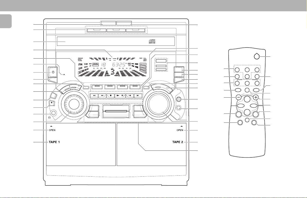
CONTROLS
English
$
#
DISC CHANGE
DISC 1 DISC 2 DISC 3
OPEN•CLOSE
%
@
!
0
2
1
9
8
7
6
5
4
3
REC
DUB
(HSD)
MINI HIFI SYSTEM
STANDBY
ON
CLOCK/
TIMER
E
R
O
M
E
T
R
N
E
PROG
J
O
PERSONAL
G
TUNER AUX
BAND
CD1 • 2 • 3
STOP• CLEARSEARCH • TUNING PLAY • SIDE
DSC
SURF
PAN
INTERACTIVE SOUND STUDIO
TAPECD
TAPE 1 • 2
STROBE VEC
HOLD
▲
PRESET
A.REV
CDR
▲
DBB
⁄
º
3
VEC
MAX
DBB
SOUND CONTROL
DISPLAY
S
O
X
A
M
V
O
L
U
M
U
CHANGER
N
D
E
DC
^
DOLBY B
DOLBY B
RDS/
CD TEXT
NEWS/TA
NEWS!
&
*
NR
NR
RDS
(
)
¡_
™
£
LEVEL
MIC
MIC
≤
∞
§
^
ª
#
ª
§
&
¤
DBB
í
à
REPEAT PROGRAM
CD DIRECT
SIDE
Å
VOLUME
É
Ç
SHUFFLE
2
TUNERTAPE 1/2CD
SLEEP TIMERAUXIS/VEC
21
DSC
ë
á
fi
›
3
ª
&
§
&
&
‹
0
≥
•
ª
8
 Loading...