


200
REF 1054728
1072919
JH 6/7/10
CLINICAL MANUAL
CLINICAL MANUAL

FOR CLINICIAN’S USE ONLY
Accessing Prescription Setting Screens
WARNING
The information on this page is ONLY for health care professionals. Remove this page from the manual
before giving the manual to the patient!
Full Menu Access Mode
The ventilator has two levels of menu access, Full and Limited. Full
Menu Access allows you to alter all available settings. Limited Menu
access permits the user to alter only those prescription parameters
that aect patient comfort, such as Rise Time, Flex, and Ramp Start
Pressure, if those parameters are available as part of the prescription.
The ventilator defaults to Full Menu Access mode.
After accessing the Main Menu, if the device is in Limited Menu
Access mode, you can use the following Setup key sequence to enter
Full Menu Access mode and be able to change prescription settings:
• Press the Down button and the Alarm Indicator/Audio
Pause button simultaneously for several seconds. This will
temporarily place the device in Full Menu Access mode.
When you perform this key sequence from the Monitor screen,
the Main Menu screen appears and an audible indicator sounds
indicating you are now in Full Menu Access mode.
When you perform this key sequence when the airow is o, the
Setup screen appears and an audible indicator sounds.
You can go into the Options menu and permanently change the
Menu Access setting to Full Menu Access. Otherwise, the device
will return to the Menu Access mode stored in the setting once you
exit the menu screens or if one minute passes without pressing any
device buttons. If you are in the Setup mode, and an SD card is in the
device, “Write Event Log to SD Card” will appear in the menu.
Note: The Full Menu Access key
sequence can be performed
either from the Power O screen
or from the Monitor screen.
Note: When the airow is o
and AC power is removed from
the device for more than 5
minutes, the device will enter
a low power mode to save
battery life. When the device is
in low power mode, the Setup
key sequence will be ignored.
Press the Start/Stop button, or
connect AC power, or insert an
SD card to exit the low power
mode.
Note: Philips Respironics
recommends that after you are
nished changing prescription
settings, and you give the
device to the patient, you set
the device back to Limited
Menu Access mode so
patients cannot change their
prescription settings.

REF 1054728
1072919
JH 6/7/10

© 2010 Koninklijke Philips Electronics N.V. All rights reserved.


Trilogy200
clinical manual
Table of Contents
FOR CLINICIAN’S USE ONLY Accessing Prescription Setting Screens ................................................... i
Chapter 1. Introduction....................................................................................................................................... 1
Package Contents ................................................................................................................. 1
Intended Use .......................................................................................................................... 2
Warnings and Cautions ......................................................................................................3
Warnings ......................................................................................................................... 3
Cautions ..........................................................................................................................8
Notes ..............................................................................................................................10
i
Contraindications ...............................................................................................................11
System Overview ................................................................................................................11
Symbols ..................................................................................................................................12
Front Panel ...................................................................................................................12
Rear and Side Panels .................................................................................................12
How to Contact Philips Respironics .............................................................................13
Chapter 2. System Description ........................................................................................................................15
Front Panel Features ..........................................................................................................15
Buttons ..........................................................................................................................15
Visual Indicators .........................................................................................................16
Display Screen .............................................................................................................16
Side and Rear Panel Features .........................................................................................17
Table of Contents

ii
Chapter 3. Modes, Features, and Alarms......................................................................................................19
Therapy Modes ....................................................................................................................19
Breath Types.................................................................................................................20
Therapy Mode Table .................................................................................................21
Pressure Control Ventilation Therapy Modes ...................................................22
Volume Control Ventilation Therapy Modes ....................................................27
Therapy Mode Features ...................................................................................................30
Flex Comfort Feature ................................................................................................30
Ramp ..............................................................................................................................31
Rise Time .......................................................................................................................32
AVAPS Feature .............................................................................................................32
Flow Pattern Types ....................................................................................................33
Sigh Feature .................................................................................................................35
Dual Prescription Feature .......................................................................................35
Triggering ....................................................................................................................36
BTPS Compensation..................................................................................................41
Ventilator Alarms ................................................................................................................41
Loss of Power Alarm ..................................................................................................41
Ventilator Inoperative Alarm .................................................................................41
Ventilator Service Required Alarm .......................................................................41
Check Circuit Alarm ..................................................................................................42
Low Circuit Leak Alarm ...........................................................................................42
High Expiratory Pressure Alarm ...........................................................................42
Low Expiratory Pressure Alarm ............................................................................42
High Internal Oxygen Alarm .................................................................................42
Circuit Disconnect Alarm ........................................................................................43
Apnea Alarm ...............................................................................................................43
High Vte Alarm ............................................................................................................43
Low Vte Alarm ............................................................................................................43
Trilogy200 clinical manual

High Vti Alarm .............................................................................................................44
Low Vti Alarm .............................................................................................................44
High Respiratory Rate Alarm .................................................................................44
Low Respiratory Rate Alarm ..................................................................................44
High Inspiratory Pressure Alarm ..........................................................................44
Low Inspiratory Pressure Alarm ...........................................................................45
High Minute Ventilation Alarm ............................................................................45
Low Minute Ventilation Alarm ..............................................................................45
Low Battery Alarm .....................................................................................................46
High Temperature Alarm .......................................................................................46
Replace Detachable Battery Alarm ......................................................................46
Ventilator Service Recommended Alarm ..........................................................46
AC Power Disconnected Alarm .............................................................................47
Keypad Stuck Alarm .................................................................................................47
Battery Discharging Stopped due to Temperature Info Message ............ 47
iii
Battery Not Charging due to Temperature Info Message ..........................47
Battery Not Charging Info Message ....................................................................47
Check External Battery Info Message .................................................................48
Battery Depleted Info Message ...........................................................................48
External Battery Disconnected Info Message ..................................................48
Detachable Battery Disconnected Info Message ...........................................48
Start On Battery Info Message ..............................................................................48
Card Error Info Message .........................................................................................48
Chapter 4. Ventilator Setup ...............................................................................................................................49
Position the Device ............................................................................................................50
Install the Air Filter .............................................................................................................50
Supply Power to the Device............................................................................................50
Using AC Power ..........................................................................................................51
Using DC Power ..........................................................................................................52
Device Power Source Indicators ...........................................................................54
Table of Contents

iv
Battery Disposal..........................................................................................................56
First Time Use ..............................................................................................................56
Connect the Breathing Circuit to the Ventilator ......................................................57
Connect a Water Trap .......................................................................................................60
Connect Supplemental Oxygen (Optional) ..............................................................61
Connect the Remote Alarm (Optional) .......................................................................62
Chapter 5. Viewing and Changing Settings ................................................................................................63
Keypad Lock Feature .........................................................................................................63
Accessing the Startup and Monitor Screens ............................................................64
Monitor Screen Indicators ......................................................................................66
On-Screen Button Panel ..........................................................................................71
Navigating the Menu Screens ........................................................................................71
Changing and Viewing Settings in Full Menu Access Mode ...............................72
Changing the Device Settings and Alarms .......................................................73
Device Settings Common to All Therapy Modes ...................................73
Additional Settings Specic to Therapy Modes .....................................78
Viewing and Changing Options Menu Items ..................................................86
Viewing the Alarm Log ............................................................................................89
Trilogy200 clinical manual
Continuous Positive Airway Pressure (CPAP) Mode ..............................78
Spontaneous (S) Mode ....................................................................................80
Spontaneous/Timed (S/T) Mode .................................................................82
Timed (T) Mode .................................................................................................82
Pressure Control (PC) Mode...........................................................................83
Pressure Control Synchronized Intermittent Mandatory
Ventilation (PC-SIMV) Mode ..........................................................................83
Control Ventilation (CV) Mode .....................................................................84
Assist Control (AC) Mode ................................................................................85
Synchronized Intermittent Mandatory Ventilation
(SIMV) Mode........................................................................................................85

Viewing the Event Log .............................................................................................90
Viewing Device Information ..................................................................................90
Updating Prescriptions Using the SD Card ...............................................................91
Changing and Viewing Settings in Limited Menu Access Mode .......................94
Activating Your Primary or Secondary Prescription ......................................95
Viewing and Changing My Settings Menu Items ...........................................96
Connecting the Ventilator to the Patient ...................................................................98
Chapter 6. Ventilator Alarms ............................................................................................................................99
Audible and Visual Alarm Indicators .........................................................................100
Audio Pause and Alarm Reset Features ................................................................... 105
What to Do When An Alarm Occurs ..........................................................................106
Alarm Summary Table .................................................................................................... 107
Chapter 7. Cleaning and Maintenance .......................................................................................................121
Cleaning the Ventilator .................................................................................................. 121
Cleaning and Replacing the Air Inlet Filter .............................................................122
Replacing the Air Inlet Path Foam .............................................................................123
v
Cleaning the Patient Circuit .........................................................................................124
Cleaning Instructions (Reusable Circuits) ...................................................... 124
Preventive Maintenance ...............................................................................................126
Chapter 8. Troubleshooting ............................................................................................................................129
Chapter 9. Accessories ......................................................................................................................................133
Adding a Humidier ....................................................................................................... 133
Adding Supplemental Oxygen to the Device ....................................................... 133
Using a Remote Alarm Unit..........................................................................................134
Using a Nurse Call System ............................................................................................ 135
Using a Secure Digital (SD) Card ................................................................................135
Using the Philips Respironics DirectView Software ............................................136
Using the Optional In-Use Bag ...................................................................................136
Traveling with the System ............................................................................................ 137
Airline Travel ...................................................................................................................... 137
Table of Contents

vi
Chapter 10. System Checkout Procedures ................................................................................................139
Tools Required .................................................................................................................. 139
Visual Inspection ..............................................................................................................139
Initial Setup ........................................................................................................................140
Settings and Alarms Tests ............................................................................................. 140
Battery Function Verication ....................................................................................... 148
Alarm and Event Log Clean-Up ..................................................................................150
Results .................................................................................................................................150
Chapter 11. Technical Specications ...........................................................................................................151
Chapter 12. Glossary .........................................................................................................................................155
Chapter 13. EMC Information ........................................................................................................................161
Index ........................................................................................................................................................................165
Limited Warranty .................................................................................................................................................169
Trilogy200 clinical manual
ap
Trilogy200
clinical manual
1. Introduction
This chapter provides an overview of the Trilogy200 device.
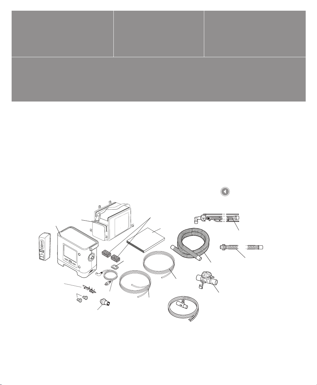
Package Contents
The Trilogy200 system may include the following components.
Some components are optional accessories that may not be
packaged with the device.
1
In-Use Bag
Trilogy200
Detachable
Battery
Universal Porting Block
(pre-installed)
O2 Inlet
Quick Connects
AC Power Cord
Whisper Swivel II
Secure Digital
(SD) Card
(pre-installed)
Reusable Gray Foam Filters
Clinical Manual
Exhalation Valve
Line (pre-assembled
to AED)
Proximal
Pressure Line
(pre-assembled
to AED)
Flow Sensor
Package Contents
Disposable Active Circuit, No Water Trap
Flexible Tubing
Active Exhalation
Device (AED)
Disposable Passive Circuit, No Water Tr
Flexible Trach Adapter
(Not Shown)
Chapter 1 Introduction

2
Intended Use
The Philips Respironics Trilogy200 system provides continuous
or intermittent ventilatory support for the care of individuals who
require mechanical ventilation. Trilogy200 is intended for pediatric
through adult patients weighing at least 5 kg (11 lbs.).
The device is intended to be used in home, institution/hospital, and
portable applications such as wheelchairs and gurneys, and may be
used for both invasive and non-invasive ventilation. It is not intended
to be used as a transport ventilator.
The system is recommended to be used only with various
combinations of Philips Respironics-approved patient circuit
accessories, such as patient interface devices, humidiers, water
traps, and circuit tubing.
Trilogy200 clinical manual

Warnings and Cautions
Caution: U.S. federal law restricts this device to sale by or on the order of a physician.
Warnings
A warning indicates the possibility of injury to the user or operator.
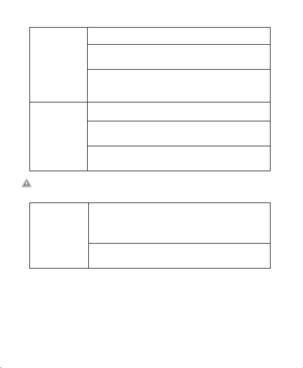
Patient Monitoring Prior to placing a patient on the ventilator, a clinical assessment should
be performed to determine:
• The device alarm settings
• Needed alternative ventilation equipment
• If an alternative monitor (i.e., an alarming Pulse Oximeter or
Respiratory Monitor) should be used
Alternative
Ventilation
Patient Disconnect
Protection
For ventilator dependent patients, always have alternate ventilation
equipment, such as a back-up ventilator, manual resuscitator, or similar
device, available.
Ventilator dependent patients should be continuously monitored by
qualied personnel. These personnel should be prepared to provide
alternate therapy in the event of ventilator failure or inoperative
equipment.
For ventilator dependent patients, do not rely on any single alarm
to detect a circuit disconnect condition. The Low Tidal Volume, Low
Minute Ventilation, Low Respiratory Rate, and Apnea alarms should
be used in conjunction with the Circuit Disconnect and Low Peak
Inspiratory Pressure alarms.
Test the operation of the circuit disconnect function daily and
whenever a change is made to the patient circuit. An increase in circuit
resistance can prevent proper operation of some alarms.
Speaking valves, Heat Moisture Exchangers (HMEs), and lters create
additional circuit resistance and may aect the performance of alarms
chosen for circuit disconnect protection.
Do not set the Low Peak Inspiratory Pressure alarm too low, or the
system may not detect large circuit leaks or a patient disconnect.
3
Chapter 1 Introduction

4
Personnel
Qualications
Modes of
Ventilation
SD Card
Prescription
Changes
Electrical
Interference
Battery Back-up
Power
Trilogy200 is a restricted medical device designed for use by
Respiratory Therapists or other trained and qualied caregivers under
the supervision of a physician.
The prescription and other device settings should only be changed on
the order of the supervising physician.
The operator of the ventilator is responsible to read and understand
this manual before use.
The device can provide therapies typically associated with both
ventilator dependent and non-dependent patients. The mode of
ventilation, circuit type, and alarm strategies should be chosen after a
clinical evaluation of each patient’s needs.
C-Flex, Bi-Flex, and AVAPS are intended for use by adult patients.
When you change the device prescription, alarms, and other settings
using the SD card, Trilogy200 requires that the caregiver review and
verify the changes prior to the changes being used by the device. The
caregiver or health care professional is responsible to ensure that the
prescription settings are correct and compatible with the patient after
using this feature. Installing the wrong prescription for a particular
patient may result in improper therapy, lack of appropriate safety
monitoring, and risk of death or injury to the patient.
This device is intended for use in the electromagnetic environment
specied in Chapter 13 of this manual. The user of this device should
make sure it is used in a compatible environment.
Portable and mobile RF communications equipment should be
used no closer to any part of the device, including cables, than the
recommended separation distance calculated using the information
provided in Chapter 13 of this manual.
The internal battery is NOT intended to serve as a primary power
source. It should only be used when other sources are not available or
briey when necessary; for example, when changing power sources.
The ventilator has a two-stage low battery alarm. The medium priority
alarm indicates that approximately 20 minutes of operation remain,
and the high priority alarm indicates that less than 10 minutes of
operation remain. Actual run time may be more or less than this and
varies with battery age, environmental conditions, and therapy.
Immediately seek an alternate power source when the “Low Battery”
alarm appears. Complete power failure and loss of therapy is imminent.
Trilogy200 clinical manual

5
Operating
and Storage
Temperatures
Do not use this device if the ambient temperature is warmer than
40˚ C (104˚ F). If the device is used at room temperatures warmer than
40˚ C, the temperature of the airow may exceed 43˚ C. This could
cause system alarms, thermal irritation, or injury to the patient’s airway.
Bacteria Filter Philips Respironics recommends that a main line outlet bacteria lter
(Part Number 342077) be used whenever the device is used for invasive
therapy or if the ventilator may be used on multiple patients.
Patient Circuits
(General)
The ventilator should only be used with patient interfaces (e.g., masks,
circuits and exhalation ports) recommended by Philips Respironics.
Proper operation of the device, including alarms, with other circuits has
not been veried by Philips Respironics and is the responsibility of the
health care professional or respiratory therapist.
When adding any components to the breathing system, the ow
resistance and dead space of the added components such as
humidiers, speaking valves, Heat Moisture Exchangers (HMEs) and
lters should be carefully considered in relation to the potential for
adverse eects on the patient’s ventilatory management and device
alarms.
Passive Circuits An exhalation port is required when using a passive circuit.
For the passive circuit, at low expiratory pressures, the ow through
the exhalation port may be inadequate to clear all exhaled gas from
the tubing – some rebreathing may occur. Rebreathing of exhaled air
for longer than several minutes can in some circumstances lead to
suocation.
Active Circuits Only use the active exhalation devices designed for Trilogy200. Philips
Respironics has not veried proper operation of other active exhalation
devices, and their use may result in improper or unsafe device
operation.
With active exhalation circuits, the exhalation device must be operating
properly for the ventilator to deliver therapy. The exhalation device
should be inspected on a daily basis and replaced whenever necessary.
System Checkout Do not use the ventilator on a patient until a system checkout has been
performed. See Chapter 10 of this manual.
To make sure the device is operating properly at start-up, always verify
that the audible tone sounds and the alarm LEDs light red and then
yellow momentarily. Contact Philips Respironics or an authorized
service center for service if these indications do not occur at start-up.
Chapter 1 Introduction

6
Remote Alarms When using a remote alarm, make sure you fully test the remote alarm
connector and cable by verifying that:
– Annunciated alarms on the ventilator are also
annunciated on the remote alarm.
– Disconnecting the remote alarm cable from the
ventilator or from the remote alarm results in an alarm
notication at the remote alarm.
The remote alarm should be tested daily.
Oxygen When administering xed-ow supplemental oxygen, the oxygen
concentration may not be constant. The inspired oxygen concentration
will vary, depending on the pressures, patient ows and circuit leak.
Substantial leaks may reduce the inspired oxygen concentration to less
than the expected value. Appropriate patient monitoring should be
used, as medically indicated, such as an alarming pulse oximeter.
This device DOES NOT alarm for loss of the low ow oxygen supply.
This device is intended to be connected to a low ow (0-15 l/min)
oxygen source such as an oxygen concentrator or other oxygen source
equipped with a pressure regulator (set to 50 PSI or less) and a ow
regulator/meter.
Do not connect the device to an unregulated or high pressure oxygen
source.
The device may result in incorrect ow and tidal volume measurements
and improper operation of related alarms if you add low ow oxygen
directly into the patient circuit or mask instead of using the oxygen
inlet on the back of the ventilator.
Oxygen supports combustion. Oxygen should not be used while
smoking or in the presence of an open ame.
If oxygen is used with the device, the oxygen ow must be turned
o when the device is not in use. Explanation of the Warning:
When the device is not in operation and the oxygen ow is left on,
oxygen delivered into the tubing may accumulate within the device’s
enclosure.
Fire or Explosion The ventilator should not be operated in the presence of ammable
gasses. This could cause a re or explosion.
Trilogy200 clinical manual

Alarms Respond immediately to any alarm. It may indicate a potentially
life-threatening condition. Refer to the Alarms and Troubleshooting
chapters for more information.
Visually monitor the patient and ventilator at all times during an Alarm
Silence period. Allowing alarms to continue without intervention may
result in harm to the patient.
If the high priority “Low Internal Battery” message appears,
immediately connect the ventilator to an alternate power source. If no
alternate power source is available, immediately place the patient on
an alternate source of ventilation.
If the “Ventilator Inoperable” alarm occurs, immediately place the
patient on an alternate source of ventilation.
You should not rely on any single alarm to detect a circuit disconnect
condition. The Low Tidal Volume, Low Minute Ventilation, Low
Respiratory Rate, and Apnea alarms should be used in conjunction with
the Circuit Disconnect alarm.
Make sure the alarm volume is set loud enough to be heard by the
caregiver. Consider the use of a remote alarm.
Trilogy200 oers the following circuit type selections:
• Passive
• Active Flow
• Active PAP (Proximal Airway Pressure )
7
Improperly
Functioning
Ventilator
The Passive circuit type provides an ESTIMATE of Vte.
Only the Active Flow circuit type directly measures exhaled tidal
volume (Vte).
The Active PAP circuit type DOES NOT measure Vte and only provides
for an indication of the delivered tidal volume (Vti).
If you notice any unexplained changes in the performance of the
device, if it is making unusual sounds, if the device or detachable
battery are dropped, if water is spilled into the enclosure, or if the
enclosure is cracked or broken, discontinue use and contact Philips
Respironics or an authorized service center for service.
Chapter 1 Introduction
8
Maintenance Follow the service recommendations provided in Chapter 7 of this
manual.
Periodically inspect electrical cords, cables, and the detachable battery
pack for damage or signs of wear. Discontinue use and replace if
damaged.
Repairs and adjustments must be performed by Philips Respironicsauthorized service personnel only. Unauthorized service could cause
death or injury, invalidate the warranty, or result in costly device
damage.
Cleaning
(Refer to Chapter 7
for detailed cleaning
instructions.)
To avoid electrical shock, always unplug the power cord from the wall
outlet before cleaning the ventilator.
Do not immerse the device in any uids or spray the device with water
or cleaners. Clean the device with a cloth dampened with an approved
cleaner.
If the device has been exposed to rain or dampness, dry the device
including the area around the power cord connection with the power
cord disconnected from the device before applying AC power.
Cautions
A caution indicates the possibility of damage to the device.
Storage The internal and detachable batteries will self-discharge in storage. If it
is desired to keep the batteries fully charged (for example, as a backup ventilator), plug the device into AC power for about eight hours
every 16 days. Alternatively, the ventilator may be left continuously
connected to AC power without battery degradation.
Allowing the batteries to fully discharge will not harm the batteries or
lose device settings, but may require a longer battery charge time prior
to use.
Trilogy200 clinical manual

9
Operating
and Storage
Temperatures
The device may only be operated at temperatures between 5˚ C and
40˚ C (41˚ F and 104˚ F).
Do not operate the device in direct sunlight or near a heating
appliance because these conditions can increase the temperature of
the airow delivered to the patient.
Prolonged operation or storage at elevated temperatures may reduce
the service life of the battery and other internal components of the
ventilator.
The ventilator has an internal and detachable Lithium-Ion Battery. Do
not expose the device or detachable battery to temperatures above
40˚ C (104˚ F) during use, or above 60˚ C (140˚ F) during storage. This
will reduce battery life and may increase the risk of re or damage the
battery.
Condensation Condensation may aect operation or accuracy of the device. If the
device has been exposed to either very hot or very cold temperatures
during storage, allow it to adjust to ambient temperature before
starting therapy.
Air Filter The reusable foam inlet lter is required to protect the ventilator from
dirt and dust. Wash periodically and replace when damaged for proper
operation.
Cooling Air Vents Do not block the cooling air vents located on the base and the rear
of the device. This may cause the device to overheat in high ambient
temperatures or at high therapy settings.
Battery Life The internal and detachable batteries wear out based on the amount
of use (hours or full charge-discharge cycles). The battery capacity and
life are also reduced by operation at higher temperatures.
Detachable Battery Only use the Philips Respironics Trilogy Detachable Battery with the
ventilator.
Cleaning Do not steam autoclave the ventilator. Doing so will destroy the
ventilator.
Do not immerse the device in liquid or allow any liquid to enter the
enclosure or inlet lter.
Do not spray water or any other solutions directly onto the ventilator.
Do not use harsh detergents, abrasive cleaners, or brushes to clean the
ventilator system. Use only cleaning agents and methods listed in this
manual.
Chapter 1 Introduction

10
Patient Circuit Exhalation valves, patient circuits, and water traps are shipped clean,
not sterile. Cleaning and disinfection of these parts should follow
individual institution processes and conform to guidelines provided by
Philips Respironics with each accessory.
External DC Power Do not use the same external battery to operate both the ventilator
and any other equipment such as power chairs.
An external battery should only be connected to the ventilator using
the Philips Respironics Trilogy External Battery Cable. This cable is
fused, pre-wired, and properly terminated to ensure safe connection
to a standard deep-cycle, lead acid battery. Use of any other adapter or
cable may cause improper operation of the ventilator.
The ventilator should only be connected to an automotive electrical
system using the Philips Respironics Trilogy Automotive Adapter
(when available). This adapter is fused, ltered, and designed for safe
connection to a standard automotive electrical system. Use of any
other adapter or cable may cause improper operation of the ventilator.
Do not operate the ventilator from a car electrical system when
starting the vehicle or jump-starting the vehicle. Electrical transients
during starting may cause improper operation of the ventilator.
Electrostatic
Discharge (ESD)
Do not use antistatic or conductive hoses or conductive patient tubing
with the device.
Notes
• This product does not contain natural latex rubber or dry
natural rubber in patient or operator accessible areas or
in the air path or breathing circuit.
Trilogy200 clinical manual

Contraindications
If the patient has any of the following conditions, consult their health
care professional before using the device in a non-invasive mode:
• Inability to maintain a patent airway or adequately clear
secretions
• At risk for aspiration of gastric contents
• Diagnosed with acute sinusitis or otitis media
• Epistaxis, causing pulmonary aspiration of blood
• Hypotension
System Overview
This ventilator provides both pressure control and volume modes of
therapy. The device can provide non-invasive or invasive ventilation.
It can be used to provide total therapy to patients as they progress
from non-invasive to invasive ventilation.
11
When prescribed, the device provides numerous special features to
help make patient therapy more comfortable. For example, the ramp
function allows you to lower the pressure when trying to fall asleep.
The air pressure will gradually increase until the prescription pressure
is reached. Additionally, the Flex comfort feature provides increased
pressure relief during the expiratory phase of breathing.
The ventilator can be operated using several dierent power
sources, including an internal Lithium-Ion battery. This battery is
automatically used when the detachable Lithium-Ion battery pack,
external Lead Acid battery, or AC power are not available.
Chapter 1 Introduction
12
O
2
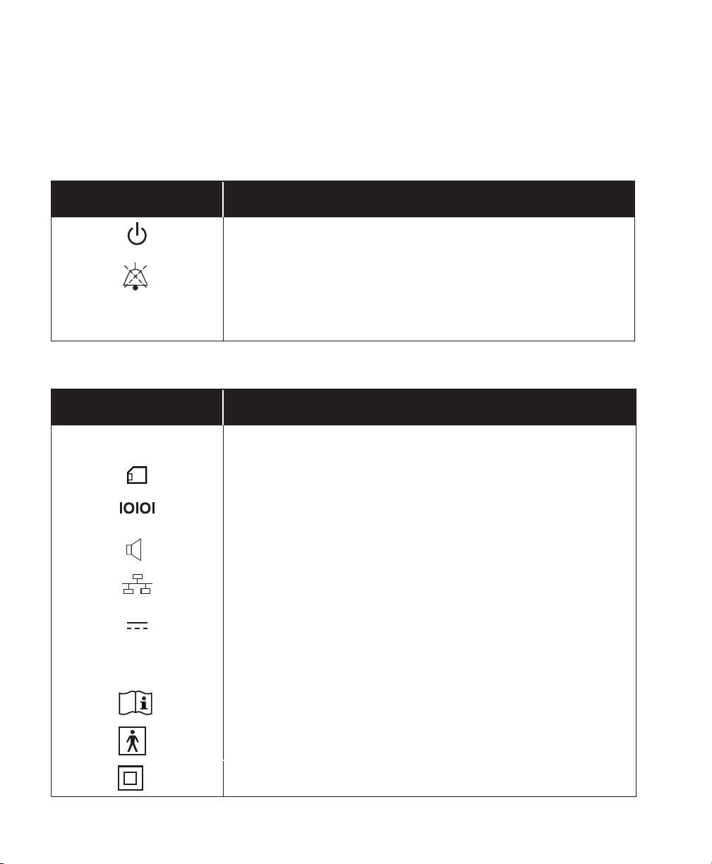
Symbols
The following symbols appear on the device.
Front Panel
Symbol Description
Therapy Start/Stop
Alarm Indicator/Audio Pause
~
AC Power Indicator
Rear and Side Panels
Symbol Description
~
AC Power Connector
Secure Digital (SD) Card Slot
Serial Port Connector
Remote Alarm Connector
Ethernet Connector
DC Power Connector
Oxygen Inlet
Consult accompanying instructions for use.
Type BF Applied Part
Class II (Double Insulated)
Trilogy200 clinical manual
Drip Proof Equipment
For Airline Use. Complies with RTCA-D0160F section 21, category M.
How to Contact Philips Respironics
To have your device serviced, contact Philips Respironics Customer
Service department at 1-724-387-4000 or 1-800-345-6443.
13
Chapter 1 Introduction

14
Trilogy200 clinical manual
Trilogy200
clinical manual
2. System Description
This chapter describes the front and rear panel device controls and
features.
15
2
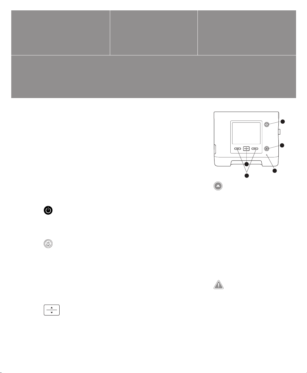
Front Panel Features
The front panel contains the control buttons, visual indicators, and
display screen.
Buttons
The following buttons are included on the front panel of the device.
1. Start/Stop Button
This button turns the airow on or o, starting or stopping
therapy.
2. Alarm Indicator and Audio Pause Button
This button serves two purposes: it temporarily silences
the audible portion of an alarm, and it also acts as an alarm
indicator. When silencing an alarm, if the cause of the alarm is
not corrected, the alarm sounds again after one minute. Each
time the button is pressed, the alarm silence period resets to one
minute. See Chapter 6 for more information.
3. Up/Down Button
This button allows you to navigate the display menu and edit
device settings.
1
3
4
Front Panel Controls and
Display Screen
Note: When you start therapy,
the display backlight and the
backlights on the buttons turn
on, the red and yellow alarm
LEDs turn on momentarily, and
an audible indicator sounds
to indicate that therapy has
started. The Startup screen
appears on the display.
WARNING
To make sure the device is operating
properly at start-up, always verify
that the audible tone sounds and
the alarm LEDs light red and then
yellow momentarily. Contact Philips
Respironics or an authorized service
center for service if these indications
do not occur at start-up.
Chapter 2 System Description
5

16
4. Left and Right Buttons
These buttons allow you to select display options or perform
certain actions specied on-screen.
Visual Indicators
Several power and alarm indicators appear on the front panel.
5. AC Power LED
In the lower right corner of the front panel, a green LED (~)
indicates that AC power is applied to the device. This light
remains on as long as adequate AC power is available.
6. Keypad Backlight LEDs
The Start/Stop, Up/Down, and Left/Right buttons all have a white
LED that lights up if the keypad backlight is turned on in the
device Options menu. See Chapter 5 for more information.
7. Red Alarm LED
On the Alarm Indicator/Audio Pause button, a red light ashes to
indicate a high priority alarm.
8. Yellow Alarm LED
On the Alarm Indicator/Audio Pause button, a yellow light
ashes to indicate a medium priority alarm. A solid yellow light
indicates a low priority alarm.
Display Screen
The display screen allows you to view settings, system status
information, real-time patient data, alarms, and logs. You can also
modify certain settings on the display screen.
See Chapter 5 for more information on viewing and modifying
device settings.
Trilogy200 clinical manual
Note: See Chapter 6 for more
information about high,
medium, and low priority
alarms.
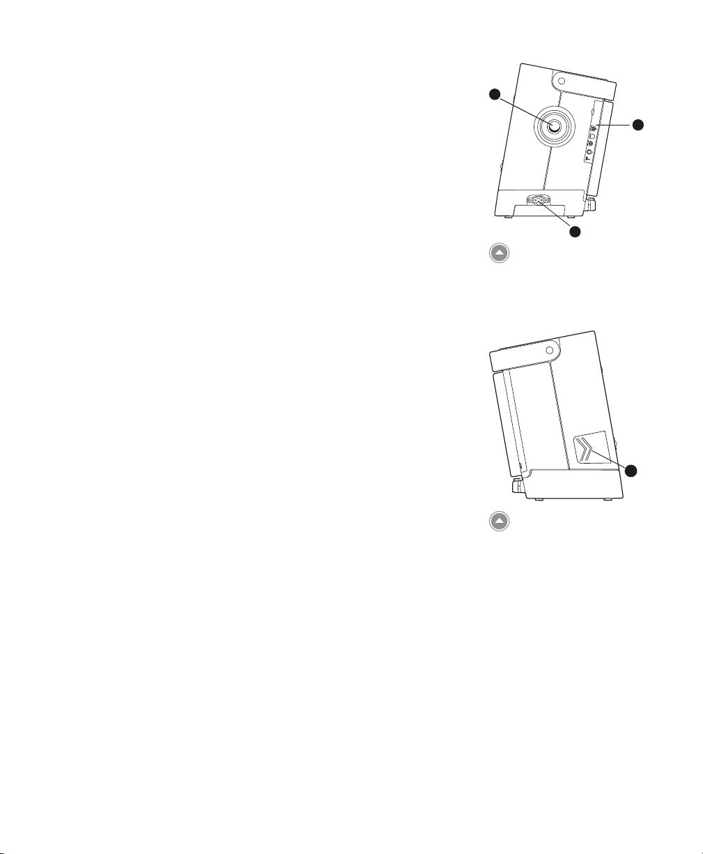
Side and Rear Panel Features
The ventilator’s side and rear panels contain the following connectors
and features, shown at right.
1. AC Power Inlet
You can plug the AC power cord into this connector, located on
the right side of the ventilator.
17
2
3
2. Breathing Circuit Connection
The breathing circuit connector is located on the right side of
the device. You can connect your circuit tubing system here. See
Chapter 4 for details.
3. Exhalation Porting Block
The porting block used here depends on the type of exhalation
device you are using. The Universal Exhalation Porting Block is
shown here. See Chapter 4 for more information.
4. Secure Digital (SD) Card Slot
On the left side of the device is a slot for the optional SD Card.
You can have the patient record usage and therapy information
from the device on the SD card.
1
Right Side Panel
4
Left Side Panel
Chapter 2 System Description
18
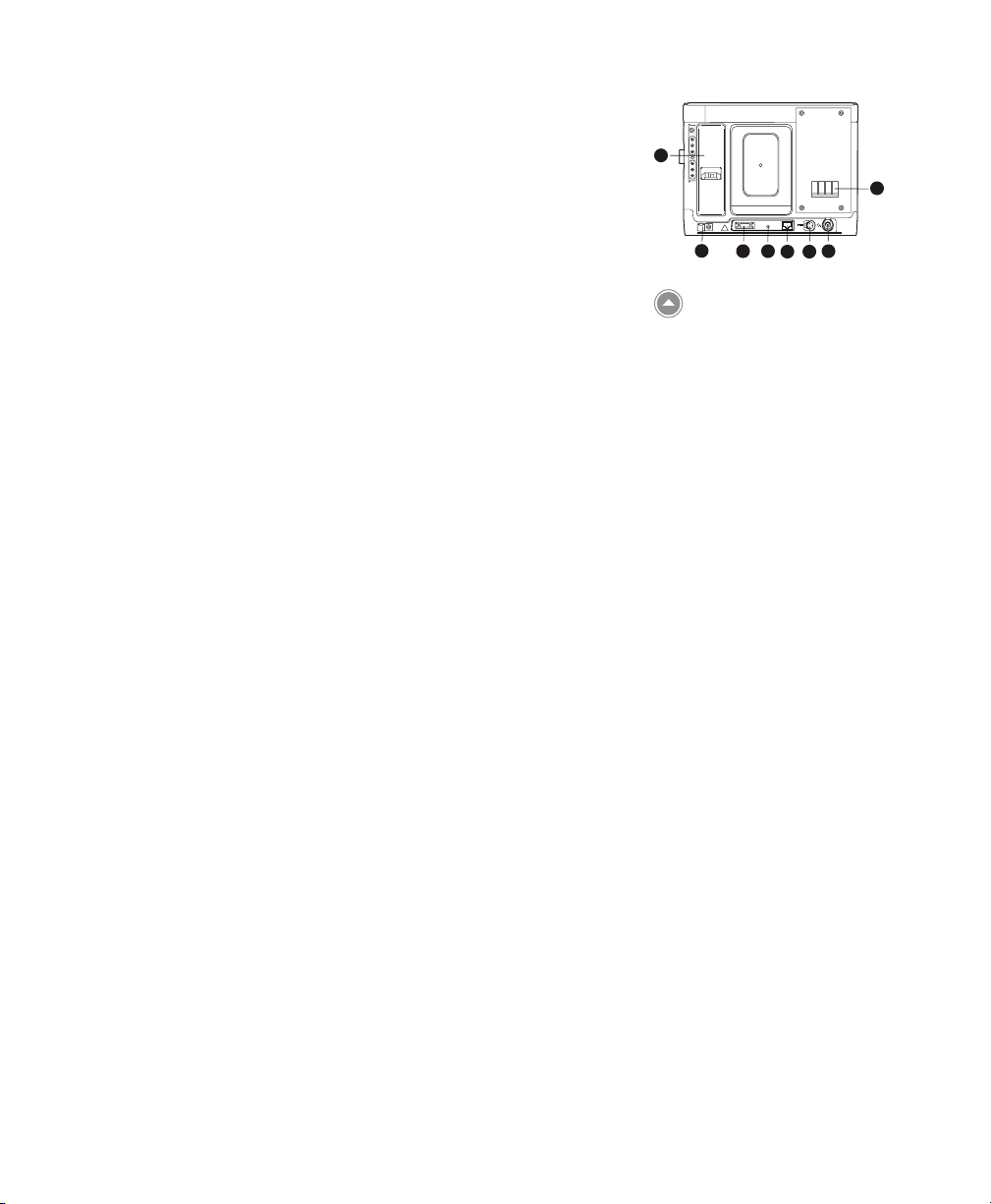
5. Serial Connector
You can use this connector to connect the device to a computer
running PC Direct or Sleepware software or to other Philips
Respironics devices such as Alice 5 and AOM. Use the Trilogy
RS232 Serial Cable to connect the ventilator to the external
device or computer.
6. Remote Alarm/Nurse Call Connector
If you are using an optional remote alarm or nurse call system
with the ventilator, you can connect the Philips Respironics
remote alarm adapter cable or nurse call adapter cable to this
connector.
7. Ethernet Connector (when available)
You can connect a PC or router to this connector to upload
therapy information to a secure web site so you can review
therapy information remotely or remotely troubleshoot and
service the device.
8. External Battery Connector (DC Power Inlet)
You can connect an external, stand-alone lead acid battery here,
using the Trilogy External Battery cable.
9. Oxygen (O2) Inlet Connector
11
12
Rear Panel
10
8
5
6
9
7
If using low ow supplemental oxygen, connect the oxygen
source to this connector using one of the O2 Inlet Quick Connects
provided with the device.
10. Air Inlet and Filter
Insert the lter supplied with the device into the air inlet.
11. Detachable Battery Pack Slot
If you are using the Philips Respironics Lithium-Ion detachable
battery pack to power the device, attach it here.
12. Cord Retainer
Secure the power cord using the cord retainer to prevent
someone from accidentally disconnecting the power cord. See
Chapter 4 for more information.
Trilogy200 clinical manual

Trilogy200
clinical manual
3. Modes, Features, and Alarms
Therapy Modes
The device provides Pressure Control Ventilation (PCV) and Volume
Control Ventilation (VCV) for non-invasive and invasive patients.
Pressure Control ventilation delivers a prescribed pressure to
the patient according to set breath rate and set inspiration time
parameters. This means that each breath is controlled so that a
prescribed amount of pressure is delivered to the patient. The device
oers six dierent Pressure Control modes of operation:
19
• CPAP – Continuous Positive Airway Pressure
• S – Spontaneous Ventilation
• S/T – Spontaneous/Timed Ventilation
• T – Timed Ventilation
• PC – Pressure Control Ventilation
• PC-SIMV – Pressure Controlled Synchronized Intermittent
Mandatory Ventilation
Volume Control ventilation delivers a prescribed inspired tidal
volume to the patient according to set breath rate and set inspiratory
time parameters. This means that each breath is controlled so that a
prescribed tidal volume is delivered to the patient. The device oers
three dierent Volume Control modes of operation:
• AC – Assist Control Ventilation
• CV – Control Ventilation
• SIMV – Synchronized Intermittent Mandatory Ventilation
Chapter 3 Modes, Features, and Alarms
 Loading...