


F1 LCD Monitor/TV |
F1-15" F1-20" |
|
Service
Service
Service
15MF605T/17
20MF605T/17
Horizontal frequencies
F1-15"30 - 49kHz
F1-20"30 - 40KHz
TABLE OF CONTENTS
Description |
Page |
|||
Important Safety Notice------------------------------- |
2 |
|||
Technical Data/Installation------------------------ |
3~8 |
|
|
|
On-Screen Display/Aging Mode------------------ |
9~11 |
|
|
|
Warning message/Factory Mode---------------- |
12~13 |
|||
Trouble shooting-------------------------------------- |
14 |
|
|
|
Failure Mode Of Panel/Wiring Diagram--------- |
15~16 |
|||
Mechanical/Electrical Instructions------------- |
17~22 |
|
|
|
Display adjustment------------------------------- |
23~24 |
|||
|
|
|
|
|
DDC DATA/Instructions-------------------------- |
25~32 |
|
|
|
ISP Instructions---------------------------------- |
33~34 |
|
|
|
Block /DC/DC POWER Diagram----------------- |
35~36 |
|
|
|
PC-IN/SCART Diagram--------------------------- |
37~38 |
|
|
|
----------VIDEO-IN/VIDEO DECODER Diagram |
39~40 |
|
|
|
Description |
Page |
T/T DECODER Diagram------------------------------ |
41 |
MCU/Scaler Diagram---------------------------- |
42~43 |
SRAM/Panel Interface Diagram---------------- |
44~45 |
Sound DECODER/Audio Diagram-------------- |
46~47 |
Scaler Board C.B.A------------------------------ |
48~49 |
Key And IR Diagram/C.B.A--------------------- |
50~51 |
YPbPr-IN/Inverter Diagram/C.B.A------------- |
52~56 |
Exploded View--------------------------------------- |
57 |
Recommended/Spare/Different parts list---- |
58~62 |
Repair Tips/Repair Flow Chart----------------- |
63~66 |
General product specification------------------ |
67~90 |
Circuit description------------------------------- |
90~91 |
Safety Test Requirements--------------------------- |
92 |
SAFETY NOTICE
ANY PERSON ATTEMPTING TO SERVICE THIS CHASSIS MUST FAMILIARIZE HIMSELF WITH THE CHASSIS AND BE AWARE OF THE NECESSARY SAFETY PRECAUTIONS TO BE USED WHEN SERVICING ELECTRONIC EQUIPMENT CONTAINING HIGH VOLTAGES.
CAUTION: USE A SEPARATE ISOLATION TRANSFORMER FOR THIS UNIT WHEN SERVICING.
REFER TO BACK COVER FOR IMPORTANT SAFETY GUIDELINES
Published by BCU Monitors |
Printed in suzhou |
Copyright reserved |
Subject to modification F Jan . 21 2005 |
|
GB 3138 106 10444 |
||||
|
|
|
|
|
|
|
|
|
|
|
|
|
|
|
|
|
|
|
|
|
|
|
|
|
|
|
|
|
|

2 |
|
Magnavox LCD TV |
Important Safety Notice |
Go to cover page
Proper service and repair isimportant to the safe, reliable operation of all HPConsumer Electronics Company** Equipment. The service procedures recommended by HP and described in this service manual are effective methods of performing service operations. Some ofthese service operations require the use of tools specially designed for the purpose. The special tools should be used when and as recommended.
It is important to note that this manual contains various CAUTIONS and NOTICES which should be carefully read in order to minimize the risk of personal injury to service personnel. The possibility exists that improper service methods may damage the equipment. It is also important to understand that these CAUTIONS and NOTICES ARE NOT EXHAUSTIVE. HP could not possibly know, evaluate and advise the service trade of all conceivable ways in which service might be done or of the possible hazardous consequences of each way. Consequently, HP has not undertaken any such broad evaluation. Accordingly, a servicer who uses a service procedure or tool which is not recommended by HP must first satisfy himself thoroughly that neither his safety nor the safe operation of the equipment will be jeopardized by the service method selected.
* * Hereafter throughout this manual, HP Consumer Electronics Company will bereferred to as HP.
WARNING
Critical components having special safety characteristics are identified with a bythe Ref. No. inthe parts list and
enclosed within a broken line*
(where several critical components are grouped in one area) along with the safety symbol on the schematics or
exploded views.
Use of substitute replacement parts which do not have the same specified safety characteristics may create shock, fire, or other hazards.
Under no circumstances should the original design be modified or altered without written permission from Philips. Philips assumes no liability, express or implied, arising out of any unauthorized modification of design.
Servicer assumes all liability. * Broken Line
FOR PRODUCTS CONTAINING LASER :
DANGERInvisible laser radiation when open. AVOID DIRECT EXPOSURE TO BEAM.
CAUTIONUse of controls or adjustments or performance of procedures other than those specified herein may result in hazardous radiation exposure.
CAUTIONThe use of optical instruments with this product will increase eye hazard.
TO ENSURE THE CONTINUED RELIABILITY OF THIS PRODUCT, USE ONLY ORIGINAL MANUFACTURER'S REPLACEMENT PARTS, WHICH ARE LISTED WITH THEIR PART NUMBERS IN THE PARTS LIST SECTION OF THIS
SERVICE MANUAL.
Take care during handling the LCD module with backlight unit
-Must mount the moduleusing mounting holes arranged infour corners.
-Do not press onthe panel, edge of theframe strongly or electric shock as this will result in damage to the screen.
-Do not scratch orpress on the panel withany sharp objects, such as pencil or pen asthis may result in damage to the panel.
-Protect the module fromthe ESD as it maydamage the electronic circuit (C-MOS).
-Make certain that treatment person s body are grounded through wrist band.
-Do not leave themodule in high temperature andin areas of high humidity for a long time.
-Avoid contact with water as it may ashort circuit within the module.
-If the surface ofpanel become dirty, please wipe it off with a soft material. (Cleaning with a dirty or rough cloth may damage the panel.)

Technical Data(15MF605T/17)
Magnavox LCD TV
 3
3
1.General
1.1. Product description
This 15 LCD Monitor/TV is specified as a display peripheral with analog video signal input and include TV function with 15 TFT
LCD display.
Horizontal scan range is 30 -49KHz and refresh range is65 - 62Hz. This scan range allows it to display resolution up to1024*768 non-interlaced at60 Hz efresh rate. The image can be adjust through OSD control, these adjustments can be stored on a board memory Including 11 factory pre - load modes.
1.2. Basic data |
|
|
|
1.2.1. LCD |
|
|
|
1.2.1.1 LPL panel |
|
|
|
Type NR. |
|
: LC150X02 |
|
Display area(mm) : 304.128(H) x 228.096(V) (15.0- inch diagonal) |
|||
Number of Pixels |
|
: 1024(H) x 768(V) |
|
Pitch ( mm ) |
|
: 0.297(H)x 0.297(V) |
|
Color pixel arrangement |
: RGB vertical stripes |
||
Display operatingmode |
: Transmissive mode,normally white |
||
Color depth |
|
: 16M colors( 6 bits with FRC) |
|
Brightness (cd/m^2) |
|
: 450(cd/m^2)(Center 1 points Typ.) |
|
Viewing angle (CR>10) |
: -65 ~ 65 (H), -55 ~ 45 (V)(Typ.) |
||
Surface treatment |
:Hard coating(3H) &Anti-glare (Haze 13%) |
||
Electrical interface |
|
: LVDS (1 pixel/clock) |
|
Response Time |
|
: 16ms(typ.) (Tr+Tf) |
|
Power Consumption (W) |
: 16.9(typ.) |
||
Contrast ratio |
: Typical 400 : 1 |
||
Module size (mm) |
|
: 332.8(W) x 262.8(H) x 18.0(D) |
|
Module weight (g) |
|
: 1750 |
|
Backlight |
|
: 4 CCFL |
|
1.2.1.2.AUO panel |
|
|
|
|
Type NR. |
|
: T150XG01 |
Display area(mm): 304.128(H) x 228.096(V) (15.0- inch diagonal) |
|||
Number of Pixels |
|
: 1024(H) x 768(V) |
|
Pitch ( mm ) |
|
: 0.297(H) x 0.297(V) |
|
Color pixel arrangement |
: RGB vertical stripes |
||
Display operatingmode |
: TN mode, normally white |
||
Color depth |
|
: 16M colors( 6 bits with FRC) |
|
Brightness (cd/m^2) |
|
: 450 nit (typ. ) @ 6.0mA |
|
Viewing angle (CR>10) |
: -70 ~ 70 (H), -60 ~ 60 (V)(Typ.) |
||
Surface treatment |
|
:Hard coating(3H) &AG |
|
Electrical interface |
|
:1ch LVDS (8bit) |
|
Response Time |
|
: 16ms(typ.) (Tr+Tf) |
|
Power Consumption(W) |
: 22 (typ.)@ 6.0mA |
||
Contrast ratio |
: Typical 450 : 1 |
||
Module size (mm) |
: 32 6.5(W) x 253.5(H) x 14.4(D) (typ.) |
||
Module weight (g) |
|
: 1350 |
|
Backlight |
|
: 4 CCFL |
|
1.2.1.3.CPT panel |
|
|
|
Type NR. |
|
: CLAA150XP03 |
|
Display area(mm) :30.4.1(H) x 228.1(V) (15.0-inch diagonal) |
|||
Number of Pixels |
|
: 1024(H) x 768(V) |
|
Pitch ( mm ) |
|
: 0.297(H) x 0.297(V) |
|
Color pixel arrangement |
: RGB vertical stripe |
||
Display operatingmode |
: Normally white, TN |
||
Color depth |
: 16.2M colors( 6 bits with FRC) |
||
Brightness (cd/m^2) |
|
: 400nit(typ.) (center, 6.5mA) |
|
Viewing angle (CR>10) |
: -70 ~ 70 (H), -60 ~ 65 (V)(Typ.) |
||
Surface treatment |
|
:Anti-glare |
|
Wide viewing angle |
|
|
|
technology |
: Optical Compensation Film |
||
Response Time |
|
: 16ms(typ.) |
|
Power Consumption(W) |
:17.1 (typ.) |
||
Contrast ratio |
: Typical 500 : 1 |
||
Module size (mm) |
|
: 32 6.5(W) x 253.5(H) x 14.0(D) (typ.) |
|
Module weight (g) |
|
: 1300 |
|
Backlight |
: CCFL, 4 tables, edge-light (top/bottom) |
||
1.2.2. |
Power supply |
|
|
AC/DC Power adapter: +16V DC/3.75A (100V~240V) Power consumption: 40 W (typical)
Power cord length and type: 1.8M, USA type
Power indicator : LED (On:Green ,Sleeping mode: Amber ) Auto power saving : EPA
1.2.3.Horizontal scan : 3049KHz
1.2.4. |
Vertical scan |
: 56 - 62 Hz |
Go to cover page
1.2.5. Input signals 1.PC Signal type
Analog Video: 0.7 Vp-p Linear , positive polarity
Sync : TTL level , separate , positive or negative polarity 2.TV signal type
RF signal : Aerial input
Video signal : S-video input
CVBS
YPbPr
3.Audio signal : S-video L/R ,YPbPr L/R audio input
PC line in
1.2.6 Input connectors
(1) Input analog D-sub connector pin assignme nt:
|
|
|
|
|
|
|
|
|
|
|
|
|
|
|
|
|
|
|
|
|
|
|
|
|
|
|
|
|
|
|
|
|
|
|
|
|
|
|
|
|
|
|
|
|
|
|
|
|
|
|
|
|
|
|
|
|
|
|
|
|
|
|
|
|
|
|
|
|
|
|
|
|
|
|
|
|
|
|
|
|
|
|
|
|
|
|
|
|
|
|
|
|
|
|
|
|
|
|
|
|
|
|
|
|
|
|
|
|
|
|
|
|
|
|
|
|
Sync polarity |
: |
|
|
|
|
|
||
-Hori.sync positive/negative -Vert.sync positive/negative

4 Magnavox LCD TV
Go to cover page
1.General
1.1. Product description
This 20" LCD Monitor/TV is specified as a display peripheral with analog video signal input and include TV function with 20"TFT LCD display. Horizontal scan range is 30-40K Hz and refresh rate 56-62Hz.
This scan range allows it to display resolution up to 800*600 non-interlaced at 60 Hz refresh rate. The image can be adjust through OSD control, these adjustments can be stored on a board memory including 8 factory pre-load modes.
1.2. Basic data
1.2.1LCD panel
Type NR. |
:A201SN02 (AUO) |
|
|
|
Display area(mm) |
: 408(H) x 306(V) (20.1-inch diagonal) |
|
|
|
Display mode |
: TN type, Normal white + SWV film |
|
|
|
Number of Pixels |
: 800(H) x 600(V) |
|
|
|
Pitch ( mm ) |
: 0.51(H) x 0.51(V) |
|
|
|
Color pixel arrangement : RGB vertical stripes |
|
|
||
Display mode |
: normally white TN |
|
|
|
Number of color |
: 16.7M ( 8 bits) |
|
|
|
Brightness (cd/m^2) |
: 450nit(typ.) |
|
|
|
Viewing angle |
: -80 ~ 80 (H), -60 ~ 60 (V)(Typ.) |
|
|
|
Response time |
: 16ms typ. (Tr+Tf) |
Sync polarity |
: |
|
Surface treatment |
: Hard Coating + AR |
|||
|
|
|||
Electrical interface |
: TTL (1 port) |
|
|
|
Total module power(W) |
: 35W(typ.) |
|
|
|
Contrast ratio |
: Typical 500 : 1 |
|
|
|
Overall dimension (mm) : 448(W) x 347(H) x 23(D)(max.) |
|
|
||
Module weight (g) |
: 3500 |
|
|
|
Backlight |
: 6 CCFL |
|
|
|
**Income inspection, please refer to panel specification.**
1.2.2.Power supply
Power consumption : Operating 55 W (typical)
Power cord length |
: 1.8M |
Power cord type |
: USA type |
Power indicator |
: LED (On: Green ,Sleeping mode: Amber ) |
Auto power saving : EPA
1.2.3.Horizontal scan : 30 - 40KHz
1.2.4. Vertical scan : 56 - 62 Hz
1.2.5. Input signals 1.PC Signal type
Analog Video: 0.7 Vp-p Linear , positive polarity
Sync : TTL level , separate , positive or negative polarity 2.TV signal type
RF signal |
: Aerial input |
|
Video signal |
: S |
-video input |
CVBS |
|
|
Y |
PbPr |
|
3.Audio signal : S |
-video L/R ,YPbPr L/R audio input |
|
|
PC line in |
|
1.2.6 |
|
Input connectors |
(1) Input analog D-sub connector pin assignment:
-Hori.sync positive/negative
-Vert.sync positive/negative

Installation
Before installation
Before proceed to install your new LCD TV ,please follow the steps and diagrams as shownto familiarize yourself with the correct and safe way of unfolding the base.
1.Place the set facing down on a fl at surface and aprotective sheet. 2.Unfold the base following the direction as shown on the diagram. 3.Place the set upright, you LCD TV is now ready for install.
INSTALLING LCD TV ON THE WALL
The stand of your LCD TV is comply with Standard VESA 75 standard, if you intend to install the LCD TV on the wall, please consult a professional technician for proper installing.The manufacture accepts no liability for installations not performed by p rofessional technician.
Television and remote control
1.Plug the DC adapter into the DC IN 16V jack on the
LCD TV. Plug the power cableinto an outlet.
2.Press POWER to turn on the LCD TV.
3.Press VOLUME + to increase the sound level. Or,
press VOLUME to lower thesound level.
4.Press CH+ or CHto select channels.
5.Point the remote control toward on the front of the LCD TV
when operating theLCD TV with the remote.
Battery installation
6.Remove the battery compartment lid on the back of the remote.
7.Place two AAA batteries in the remote. Be sure the (+) and ( -)
ends of thebatteries line up as marked inside the battery compartment.
8. Reattach the battery compartment lid.
Magnavox LCD TV
 5
5
Go to cover page
6 Magnavox LCD TV
Go to cover page
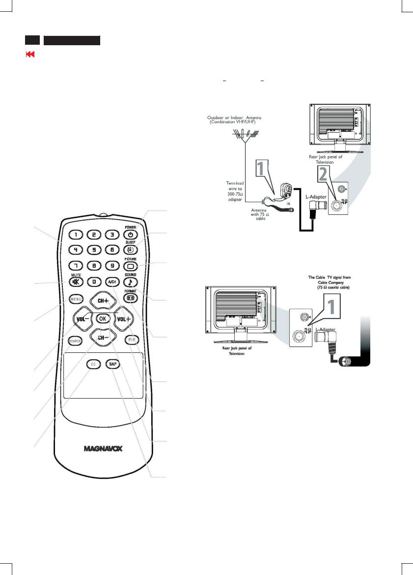
Installation
1.Power |
: Power On/Standby |
2.Numerica keys |
: (0~9) ,Channel setting |
3.Mute |
: Sound mute function |
4.Prev-CH |
: Recall previous CH |
5.Menu |
: Main menu select and OK key |
6.VOL- |
: Left/Volume Down |
7.OK |
: OK |
8.Source |
: Source select for PC,Tuner,CVBS,S-video,HD |
9.Closed cap. |
: Closed caption on/off |
10.SAP(2nd audio) |
: Sound select |
11.CH- |
: Down/Channel Down |
12.PIP |
: PIP size select (Small/Medium/Large/PBP) |
13.VOL+ |
: Right/Volume Up |
14.CH+ |
: Up/ Channel Up |
15.Display Format : Select display format (4:3, Expand 4:3, |
|
|
Compress 16:9) |
16.Smart Sound |
: Select sound effect |
|
(Personal/News/Music/Theatre) |
17.Smart Picture |
: Select picture effect (Personal/Movie/Sports/ |
|
weak signal/multimedia/Night) |
18.Sleep Timer |
: Sleep timer 15,30,60,120,180,240 OFF |
|
1 |
2
18
17
3
16
5
15
6
13
4
8
12
7
11 14
9
10
ANTENNA CONNECTION
Acombination antenna receives normal broadcast channels (VHF 2 13 and UHF 14 69). Your connection is easy because there is only one 75  (ohm) antenna jack on the back of your TV, and that
  s where the antenna goes.
BASIC CABLE TV CONNECTION
Your Cable TV signal into your home may be a single, 75 (ohm) cable. If so, this connection is very simple. Follow the step below to connect your Cable TV signal to your new LCD TV.
1.Connect the Cable TV signal to one end of the supplied L-Adapter as shown, and connect the other end of the adapter to the TV jack on the LCD TV.
CABLE BOX CONNECTIONS
If you have a Cable Box, follow either set of these steps to complete your connections.
Cable Box with RF In/Out Jacks
This connection will not supply Stereo sound to the LCD TV. 1.Connect the Cable TV signal to the IN jack
(or RF IN or CABLE IN) on the Cable Box.
2.Connect an RF coaxial cable (not supplied) to the OUT jack (or TO TV or RF OUT) of the Cable Box.
3.Connect the other end of the coaxial cable to one end of the supplied L-Adapter as shown, and connect the other end of the adapter to the TV jack on the LCD TV.
4.Plug the DC adapter into the DC IN 16V jack on the LCD TV. Plug the power cable into an outlet.
5.Set the Channel 3/4 (or Output channel) switch of the Cable Box to 3 or 4. Set the TV to the same channel. When watching TV programming, change channels at the Cable Box, not the LCD TV.

Installation
Magnavox LCD TV
 7
7
Cable Box with Audio/Video Out Jacks
Stereo sound to theLCD TV.
1.Connect the Cable TV signal to the IN jack (or RF IN or CABLE IN) on the Cable Box.
2.Using an RCA-type video cable (not supplied) connect one end of the Video cable to the Video Out jack of the Cable Box. Connect the
other end of the cable tothe yellow VIDEO jack on the side of theTV.
Video cablesare usually marked withyellow and are available from Magnavox orelectronics retailers. Video jacks on most equipment
are yellow.
3. Using RCA-type, stereo audio cables (not supplied), connect one end of the cablesto the left and right Audio Out jacks of the Cable Box. Connect the other end of thatcable to the Audio jack on the side of the LCD TV. Audio cables are usually markedwith red and white and are available fromMagnavox or electronics retailers.The rightaudio jack is red and the left audio jack is
colors.
4. Plug the DC adapter into the DC IN 16V jack on the LCD TV. Plug the power cableinto an outlet.
Go to cover page
AUDIO/VIDEO INPUT CONNECTIONS
The AUDIO and VIDEO In jacks on the rear of the LCD TV enable quick connections of other equipment. Connect a VCR, DVD Player, Video Game, Camcorder,etc., to these jacks. To view the material playing on the other equipment, Set the LCD TV to its AV Mode.
1. Connect a RCA-style video cable(usually yellowor marked CVBS) To the VIDEO OUT jacks of the other equipment (DVD Player, Camcorder,etc.) and to the yellow VIDEO jack on the side of the LCD TV.
2. Connect RCA-style audio cables (usuallyred and white) to the AUDIO OUT (leftand right) jacks on the other equipment. Connect the other end of the cables to the AUDIO jack on the side of the LCD TV.
3.Plug the DC Adapter into the DC IN
power cable into an outlet. Turn on the TV and otherequipment. 4.Press the Source button to set the TV to AV Mode.
5.Press PLAY on the other equipment to view its material on the TV.
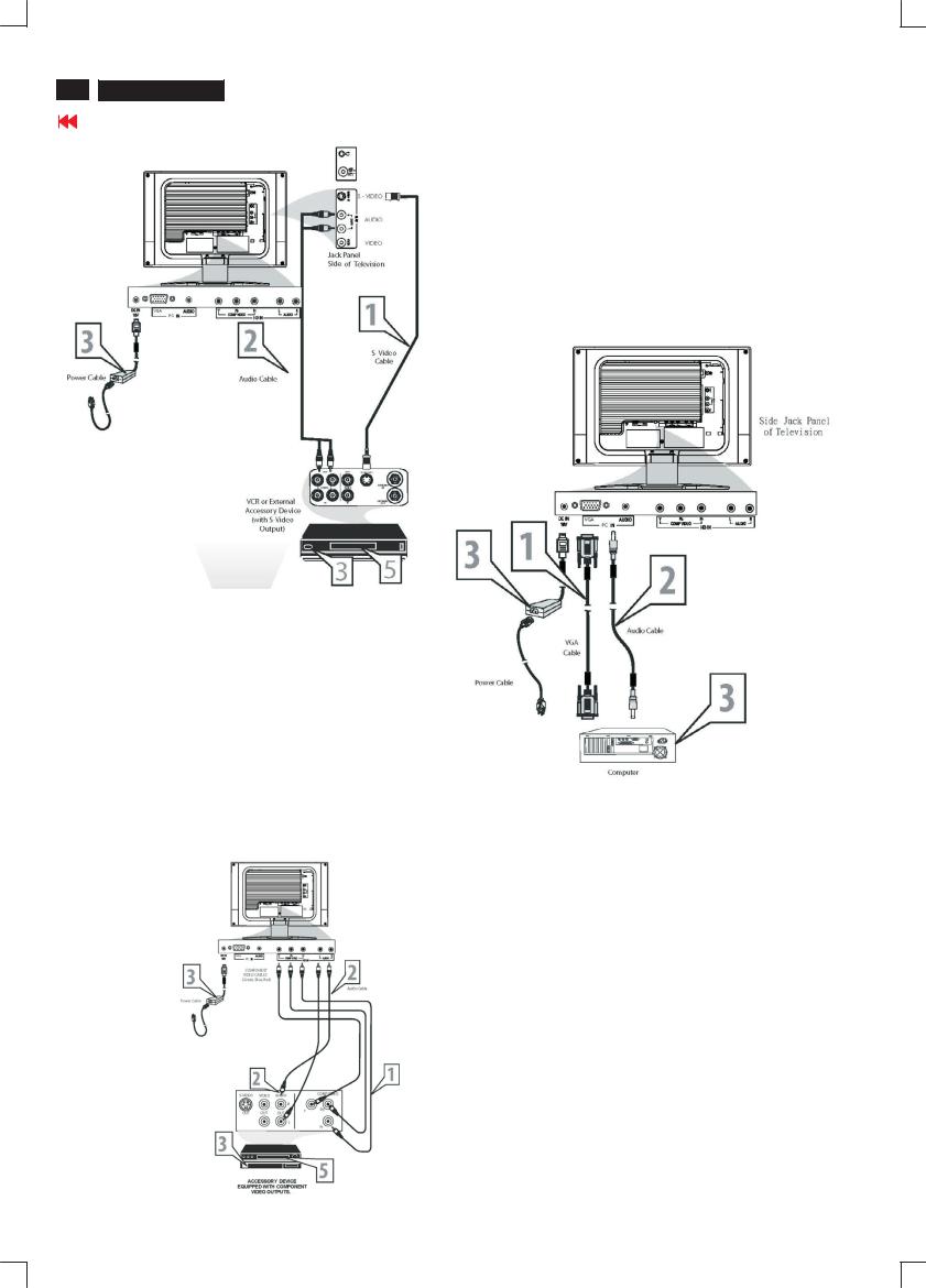
The S-Video connection on the rear of the LCD TV can provide you with better LCD
the playbackof accessory sources such as DBS (digital broadcast satellite), DVD (digital video discs), video games, and VHS VCR (video casse tte recorder) tapes than the normal antenna picture connections.
Note: The accessory device must have an S-VIDEO OUT (put) jack in order for you to complete the connection on this page.
1.Connect an S-Video cable to the S- VIDEO jack of the other equipment(DVD Player,Camcorder, etc.) and to the S - VIDEO jack on the rear of the LCD TV.
2.Connect RCA-style audio cables (usually
red and white) to the AUDIO OUT (left and right) jacks on the other equipment.Connect the other end of the cables to the AUDIO
jack on the side of the LCD TV.
3.Plug the DC Adapter into the DC IN 16V jack on the LCD TV. Plug the power cableinto an outlet. Turn on the LCD TV and other equipment.
4.Press the Source button to sethe LCD TV to its S-VIDEO mode. 5.Press PLAY on the other equipment toview its material on the LCD TV.
8 Magnavox LCD TV
Go to cover page
Installation
PC (MONITOR) CONNECTION
This LCD TV can be used as a PC . Your computer will have to be Equipped with a VGA type video output and VGA cable.
1. Connect one end of the VGA Video cable (not supplied) to the Monitor(video) output on the computer, while connecting the other ends to the VGA INPUT jack on the LCD TV.
2. Although audio connections are not required, the LCD TV can Reproduce the computers audio out by an AUDIO ADAPTER to the Audio output jack on the computer (if available) while connecting the other ends of the Audio cables to the PC AUDIO Jacks on the bottom of the TV.
3.Plug the DC Adapter into the DC IN 16V jack on the LCD TV. Plug the power cable into an outlet. Turn on the LCD TV and PC.
4.Press the SOURCE button until PC MODE appears on the screen.
COMPONENT (YPBPR) CONNECTIONS
Component Video input provide the highest possible color and picture resolution in the playback of digital signal source material, such as with DVD players.
Note: The accessory device must have an component(YPbPr) output jack in order for you to complete the connection on this page.
1. Connect the component (Y, Pb, Pr) Video OUT jacks from the DVD player(or similar device) to the COMP(onent) VIDEO Input jacks on the bottom of the LCD TV.
2.Connect the red and white AUDIO CABLES to the Audio (left ad right) output jacks on the rear of the accessory device to the AUDIO IN jack. Connect the other end of the cable to the Audio jack on the rear of
LCD TV.
3. Plug the DC Adapter into the DC IN 16 V jack on the LCD TV. Plug the power cable into an outlet. Turn on the LCD TV and other equipment.
4.Press the SOURCE button on the remote control to select HD. HD will appear in the upper left corner on the TV screen.
5.Insert a DVD disc into the DVD player and press the PLAY button on the DVD Player.

On Screen Display
Magnavox LCD TV
 9
9
Go to cover page
|
|
PC MODE |
|
|
|
1st Layer |
2nd Layer |
|
3rd Layer |
|
|
PICTURE |
|
|
|
|
|
|
SMART PICTURE |
|
NORMAL |
|
|
|
|
|
WARM |
|
|
|
|
|
COOL |
|
|
|
BRIGHTNESS |
|
|
|
|
|
CONTRAST |
|
|
|
|
|
AUTO ADJUST |
|
YES |
|
|
|
|
|
IN PROGRESS |
|
|
|
|
|
STORE? |
YES |
|
|
|
|
|
NO |
|
|
MANUAL ADJUST |
|
PHASE |
|
|
|
|
|
CLOCK |
|
|
|
|
|
HORIZONTAL |
|
|
|
|
|
VERTICAL |
|
|
AUDIO |
|
|
|
|
|
|
SMART SOUND |
|
PERSONAL |
|
|
|
|
|
NEWS |
|
|
|
|
|
MUSIC |
|
|
|
|
|
THEATRE |
|
|
|
SETTINGS |
|
TREBLE |
|
|
|
|
|
BASS |
|
|
|
|
|
BALANCE |
|
|
|
STEREO |
|
STEREO |
|
|
|
|
|
|
|
|
|
VIRTUAL SURROUND |
|
VIRTUAL SURROUND |
|
|
|
|
|
OFF |
|
|
|
AVL |
|
YES |
|
|
|
|
|
NO |
|
|
FEATURES |
|
|
|
|
|
|
PIP |
|
SIZE |
OFF |
|
|
|
|
|
SMALL |
|
|
|
|
|
MEDIUM |
|
|
|
|
|
LARGE |
|
|
|
|
|
PBP |
|
|
|
|
VIDEO |
TV |
|
|
|
|
|
AV |
|
|
|
|
|
S-VIDEO |
|
|
|
|
|
COMPONENT |
|
|
|
|
AUDIO |
PC |
|
|
|
|
|
PIP |
|
|
|
|
DISPLAY |
ICON1 |
|
|
|
|
|
ICON2 |
|
|
|
|
|
ICON3 |
|
|
|
|
|
ICON4 |
|
|
SOURCE |
|
PC |
|
|
|
|
|
TV |
|
|
|
|
|
AV |
|
|
|
|
|
S-VIDEO |
|
|
|
|
|
HD |
|
|
INSTALL |
|
|
|
|
|
|
LANGUAGE |
|
ENGLISH |
|
|
|
|
|
FRANÇ AIS |
|
|
|
|
|
ESPAÑ OL |
|
|
|
FACTORY RESET |
|
YES? |
|
|
|
TV / AV/ S-VIDEO / HDTV MODE |
|
|
|
|
1st Layer |
2nd Layer |
|
3rd Layer |
4th Layer |
5th Layer |
PICTURE |
|
|
|
|
|
|
SMART PICTURE |
|
PERSONAL |
|
|
|
|
|
MOVIES |
|
|
|
|
|
SPORTS |
|
|
|
|
|
WEAK SIGNAL |
|
|
|
|
|
MULTIMEDIA |
|
|
|
|
|
NIGHT |
|
|
|
BRIGHTNESS |
|
|
|
|
|
CONTRAST |
|
|
|
|
|
COLOR |
|
|
|
|
|
SHARPNESS |
|
|
|
|
|
TINT |
|
|
|
|
AUDIO |
|
|
|
|
|
|
SMART SOUND |
|
PERSONAL |
|
|
|
|
|
NEWS |
|
|
|
|
|
MUSIC |
|
|
|
|
|
THEATRE |
|
|

10 
 Magnavox LCD TV
Go to cover page
On Screen Display
AUDIO |
SETTINGS |
TREBLE |
|
|
|
|
|
|
BASS |
|
|
|
|
|
|
BALANCE |
|
|
|
|
|
STEREO |
STEREO |
|
|
|
|
|
|
SAP |
|
|
|
|
|
|
MONO |
|
|
|
|
|
VIRTUAL SURROUND |
VIRTUAL SURROUND |
|
|
|
|
|
|
OFF |
|
|
|
|
|
AVL |
YES |
|
|
|
|
|
|
NO |
|
|
|
|
FEATURES |
|
|
|
|
|
|
|
SOURCE |
PC |
|
|
|
|
|
|
TV |
|
|
|
|
|
|
AV |
|
|
|
|
|
|
S-VIDEO |
|
|
|
|
|
|
HD |
|
|
|
|
|
PICTURE FORMAT |
4:3 |
|
|
|
|
|
|
EXPAND 4:3 |
|
|
|
|
|
|
COMPRESS 16:9 |
|
|
|
|
|
PICTURE ALIGNMENT |
|
|
|
|
|
|
AUTO LOCK |
LOCK PROGRAM |
|
|
|
|
|
|
CHANGE CODE |
YES |
|
|
|
|
|
CLEAR ALL |
ON |
|
|
|
|
|
|
OFF |
|
|
|
|
|
BLOCK OPTION |
ON |
|
|
|
|
|
|
OFF |
|
|
|
|
|
MOVIE RATING |
G |
ON/OFF |
|
|
|
|
|
PG |
ON/OFF |
|
|
|
|
|
PG13 |
ON/OFF |
|
|
|
|
|
R |
ON/OFF |
|
|
|
|
|
NC17 |
ON/OFF |
|
|
|
|
|
X |
ON/OFF |
|
|
|
|
TV RATING |
TV Y |
ON/OFF |
|
|
|
|
|
TV Y7 |
|
BLOCK |
ON/OFF |
|
|
|
|
|
FV |
ON/OFF |
|
|
|
TV G |
ON/OFF |
|
|
|
|
|
TV PG |
|
BLOCK |
ON/OFF |
|
|
|
|
|
V |
ON/OFF |
|
|
|
|
|
S |
ON/OFF |
|
|
|
|
|
L |
ON/OFF |
|
|
|
|
|
D |
ON/OFF |
|
|
|
TV 14 |
|
BLOCK |
ON/OFF |
|
|
|
|
|
V |
ON/OFF |
|
|
|
|
|
S |
ON/OFF |
|
|
|
|
|
L |
ON/OFF |
|
|
|
|
|
D |
ON/OFF |
|
|
|
TV MA |
|
BLOCK |
ON/OFF |
|
|
|
|
|
V |
ON/OFF |
|
|
|
|
|
S |
ON/OFF |
|
|
|
|
|
L |
ON/OFF |
|
CLOSED CAPTION |
CAPTION MODE |
CC1 |
|
|
|
|
|
|
CC2 |
|
|
|
|
|
|
CC3 |
|
|
|
|
|
|
CC4 |
|
|
|
|
|
|
TXT1 |
|
|
|
|
|
|
TXT2 |
|
|
|
|
|
|
TXT3 |
|
|
|
|
|
|
TXT4 |
|
|
|
|
|
|
CC MUTE |
|
|
|
|
|
CC DISPLAY |
ON |
|
|
|
|
|
|
OFF |
|
|
|
INSTALL |
|
|
|
|
|
|
|
LANGUAGE |
ENGLISH |
|
|
|
|
|
|
FRANÇ AIS |
|
|
|
|
|
|
ESPAÑ OL |
|
|
|
|
|
TUNER MODE |
ATENNA |
|
|
|
|
|
|
CABLE |
|
|
|
|
|
|
AUTO |
|
|
|
|
|
AUTO PROGRAM |
START? |
|
|
|
|
|
CHANNEL EDIT |
CHANNEL |
|
|
|
|
|
|
SKIPPED |
ACTIVE |
|
|
|
|
|
|
SKIPPED |
|
|
|
|
MANUAL FINE TUNE |
|
|
|
|
|
|
FACTORY RESET |
YES? |
|
|
|
|
Aging Mode
ATTENTION
NO VIDEO INPUT
Access Aging.. Mode
Step 1 : Select the source "PC" and then turn off LCD-TV, and disconnect Interface Cable between Monitor and PC.
Step 2 : [Push "power " button and then push the "VOL- " and "VOL+" buttons at the same time immediately and hold it] untill comes out
" AGING screen" then release all buttons.
Bring up:
AGING...
After 55 seconds, bring up:
After 5 seconds, bring up:
AGING...
After 55 seconds, bring up:
Magnavox LCD TV
 11
11
Go to cover page
----------
----------
repeatly
Connect Signal cable again=> go back to normal display

12 
 Magnavox LCD TV
Go to cover page
Warning Message
1.Automatic adjustment (for factory only)
Press Volume+ and Volumeon front key at the same time (PC mode only). It adjusts PC image to the best and save the screen automatically. 2. OUT OF RANGE
If PC input timing is out of range, it shows "OUT OF RANGE " warning message on the center of the screen. The range of horizontal frequency is between 14 - 63 KHz. The range of vertical frequency is between
45 - 76 Hz. The OSD won' t timeout. 3.NO VIDEO INPUT
When PC input timing has either horizontal frequency or vertical frequency. Or neither has horizontal frequency nor vertical frequency. It shows on the center of the screen for 30 seconds, then it will enter sleep mode.
Factory Mode
Access factory. Mode
how to get into factory mode menu
Step 1 : Select the source "PC" and then turn off LCD-TV.
Step 2 : [Push "power " button and then push the "VOL- " and "VOL+" buttons at the same time immediately and hold it] about five seconds then release all buttons.
Press "menu"button and bring up factory mode indication as shown in Fig.1
MAIN CONTROLS |
1024X768@60HZ |
|
|
PICTURE |
SMART PICTURE |
AUDIO |
BRIGHTNESS |
FEATURES |
CONTRAST |
INSTALL |
AUTO ADJUST |
|
MANUAL ADJUST |
F1/FL1 NAFTA V1.01.05 041208 LG15XGA
Fig.1
Use the CHNNELand CHNNEL+ to select the "F1/FL1 NAFTA V1.01. 05 041208 LG15XGA" and then press the "VOL +" button
Menu Item |
Description |
Scalar Gain R G B |
Scalar Gain for Normal/Warm/Cool in PC mode. |
Auto-Color |
Adjust color from received signal (either in PC or |
|
HDTV mode). |
ADC Offset R G B |
Adjust AD 9883 for PC ADC offset. |
ADC Gain R G B |
Adjust AD 9883for PC ADC gain. |
PC Offset R G B |
PC analog scalar offset. |
711X SDTV Brightness |
Adjust SA 7119 SDTV brightness. |
711X SDTV SAT. |
Adjust SA 7119 SDTV saturation. |
711X SDTV Contrast |
Adjust SA 7119 SDTV contrast. |
711X SDTV TINT |
Adjust SA 7119 SDTV tint (hue). |
TV Shift H V |
Adjust TV screen position horizontally/vertically. |
HD Shift H V |
Adjust HDTV screen position |
|
horizontally/vertically. |
Show Lock Message |
Show OSD lock message. |
HDTV ADC Offset R G B |
Adjust AD 9883 for HDTV ADC offset. |
HDTV ADC Gain R G B |
Adjust AD 9883 for HDTV ADC gain. |
Video Scalar Gain R G B |
Adjust scalar gain for Video mode. |
Scalar Hue |
Adjust scalar hue. |
|
|
Magnavox LCD TV
 13
13
Go to cover page

14 
 Magnavox LCD TV
Go to cover page
Trouble shooting
No Power
.Check the TV power cord. Disconnect the power cord from the power outlet for 10 seconds, then reinsert the plug into the outlet. Press POWER to turn on the TV again.
.Make sure the outlet is not on a wall switch.
.Make sure a fuse has not blown at the power outlet. No Picture
.Check the antenna or Cable TV connections. Connect the antenna or Cable TV signal securely to the TV’s 75ohm jack on the rear of the TV.
.Set TUNER MODE correctly. Details are on page 15.
.Activate AUTO PROGRAM to find all available channels.
In case you hear only sound and don’t see any picture in S-Video or Video (CVBS) mode. Please check if you have connected Video signal to S-Video or Video (CVBS) input. Only one of the two video inputs can be connected to sound. This means that the same sound can be heared in S-Video and Video (CVBS) mode.
No Sound
.Press the VOL+ and VOLbuttons to adjust the volume.
.Press the MUTE button on the remote control to cancel or restore the volume.
.If you have connected other equipment to the TV (such as a VCR or DVD Player), make sure the audio cables are connected securely between the TV and the other equipment.
.Check the SOUND settings.
.In case you hear wrong sound in S-Video or Video (CVBS) mode. Please check if you have connected the right sound signal to AV in (S-Video or Video input). Only one of the two video inputs can be connected to sound, but both video signals can be connected. This means that only one of the two sound inputs can be heared in S-Video and Video (CVBS) mode.
Remote Control does not work.
.Check the batteries. If necessary, replace them with two AAA heavy duty (zinc chloride) or alkaline batteries.
.Clean the remote control as well as the remote control sensor on the front of the TV.
.Check the TV power cord. Disconnect the power cord from the power outlet for 10 seconds, then reinsert the plug into the outlet. Press POWER to turn on the TV again.
.Make sure the outlet is not on a wall switch.
.Make sure a fuse has not blown at the power outlet.
.Always point the remote control toward the front of the TV (toward the remote sensor).
.Make sure that you use the supplied Magnavox Remote control, only the supplied Magnavox Remote control can be used with this LCD-TV set. TV displays wrong channel or no channels.
.Repeat channel selection.
.Add the channel number(s) into the TV’s memory. Use STORE.
.Make sure TUNER MODE is set correctly.
Then activate AUTO PROGRAM to set up all available channels.
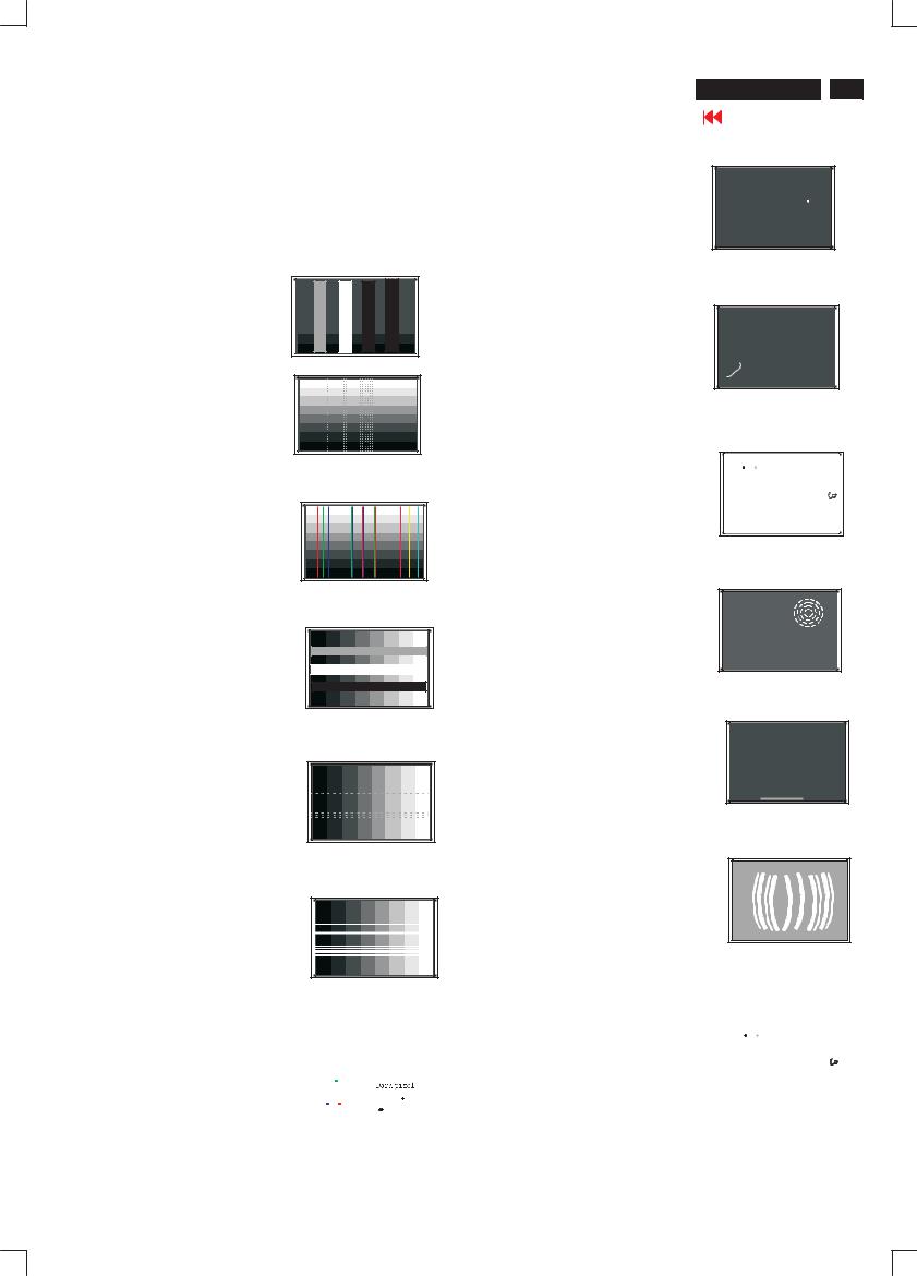
Failure Mode Of Panel
Quick reference for failure mode of LCD panel
this page presents problems that could be made by LCD panel.
It is not necessary to repair circuit board. Simply follow the mechanical Polarizer has bubbles instruction on this manual to eliminate failure by replace LCD panel.
Failure description |
Phenomenon |
|
|
|
|
|
|
|
|
|
|
|
|
Vertical block defect
Polarizer has bubbles
Vertical dim lines
Magnavox LCD TV
 15
15
Go to cover page
Foreign material inside polarizer. It shows liner or dot shape.
Vertical lines defect (Always bright or dark)
Concentric circle formed
Horizontal block defect
Bottom back light of LCD is brighter than normal
Horizontal dim lines
Back light un-uniformity
Horizontal lines defect (Always bright or dark)
|
|
|
|
|
|
Backlight has foreign material. |
|
|
|
|
|
|
|
|
|
|
|
|
|
Has bright or dark pixel |
|
|
|
|
|
Black or white color, liner or |
|
|
|
|
|
|
|
|
circular type |
|
|
|
|
|
|
|
|
|
|
|
|
|
|
|
|
|
|
|
|
|
|
|
|
|
|
|
|
|
|
|
|
|
|
|
|
|
|
|
|
|
|
|
|
|
|
|
|
|
|
|
|
|
|

16 
 Magnavox LCD TV
Go to cover page
Wiring diagram
Magnavox LCD TV
 17
17
Go to cover page
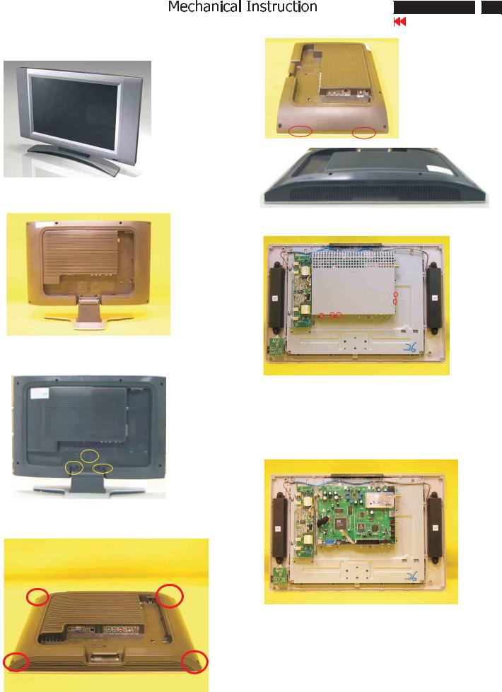
Front view
Fig.5
Fig.1
Back view, remove the cover as Fig.2
Fig.6
Fig.2
Fig.7
Remove the base:
unscrew the screws as Fig.3
Fig.3 |
Remove the Matel frame board |
- Remove the five screws
- Remove the matel frame board as shown in Fig.8
Remove the back cover,
unscrew the screws as Fig.4 and the open the
clicks and then remove the back cover as Fig.5 Fig.6 Fig.7
Fig.8
Remove the inverter board ,YPbPr-in and scaler board
unscrew the screws and disconnect the connector as shown in Fig.9
Fig.4

18 
 Magnavox LCD TV
Go to cover page
Fig.9
Fig.13
Fig.10
Fig.11
Fig.14
Fig.12

Electrical instruction(15MF607T/17) Magnavox LCD TV
 19
19
Go to cover page
1.General points
1.1During the test and measuring, supply a distortion free AC mains Voltage to the apparatus via an isolated transformer with low Internal resistance.
1.2All measurements mentioned hereafter are carried out at a normal mains voltage (90 - 132 VAC for USA version, 195 -264 VAC for EUROPEAN version, or 90 - 264 VAC for the model with full range power supply, unless otherwise stated.)
1.3All voltages are to be measurement or applied with respect to ground, unless otherwise stated.
1.4The test has to be done on a complete set including LCD panel in a room with temperature of 25 +/- 5 degree C.
1.5All values mentioned in these test instruction are only applicable of a Well aligned apparatus, with correct signal.
1.6The letters symbols (B) and (S) placed behind the test instruction Denotes (B): carried out 100% inspection at assembly line
(S): carried out test by sampling
1.7The white balance (color temperature), has to be tested in subdued Lighted room.
1.8Repetitive power on/off cycle are allowed except it should be avoided within 6 sec.
2. Input signal
2.1.1 PC Signal type
Analog Video : 0.7 Vp-p linear, positive polarity
Separate Sync. : TTL level, separate, positive or negative polarity
Audio signal |
: Mini-jack audio input |
Input level: 500 mVrms ((Speaker outpout 3W when Input level
> 630mVrms and Volume control at 100%))
Signal source: pattern generator format as attachment
(table 1 to 11) Reference generator : CHROMA 2200 or 2250
2.1.2 TV Signal type
RF Signal : Aerial input, NTSC cable and antenna system.
2.3 TV input signal Channel and pattern for Nafta model (Table1) Signal Distribution Table ( NTSC)
Video signal : Cinch input, CVBS with NTSC and PAL system.
Level: 1.0Vp-p (0.7V video + 0.3V sync.)
S video input: Y/C signal, NTSC and PAL system.
Level: Y: 1.0Vp-p (0.7V video + 0.3V sync.)
C: +/- 0.3V.
Component input: Cinch G/B/R-> YPbPr cinch input.
Level: Y: 1.0Vp-p Pb/Pr: +/- 0.35V
Audio signal : Side cinch R/L for CVBS and S-video
Bottom cinch R/L for component input.
Input level: 500 mVrms ((Speaker outpout 3W when Input level
>630mVrms and Volume control at 100%))
2.2PC Input signal mode
PRE-LOAD VIDEO RESOLUTION
Mode 3, 6, 7, 10 are preset modes that should pass QA inspection. Mode 1, 2, 4, 5, 8, 9, 11 will run auto adjustment only, and W/O QA checking.
Dot rate (MHz) |
H.freq |
Mode |
Resolution |
V.freq (Hz) |
|
|
|
|
|
|
|
1 |
25.175 |
31.469 |
IBM VGA |
640 * 350 |
70.087 |
|
|
|
|
|
|
2 |
28.322 |
31.469 |
IBM VGA |
720 * 400 |
70.087 |
|
|
|
|
|
|
3 |
25.175 |
31.469 |
IBM VGA |
640 * 480 |
59.940 |
|
|
|
|
|
|
4 |
30.240 |
35.000 |
MACINTOSH |
640 * 480 |
66.667 |
|
|
|
|
|
|
5 |
31.500 |
37.500 |
VESA |
640 * 480 |
75.000 |
|
|
|
|
|
|
6 |
36.000 |
35.156 |
VESA |
800 * 600 |
56.250 |
|
|
|
|
|
|
7 |
40.000 |
37.879 |
VESA |
800 * 600 |
60.317 |
|
|
|
|
|
|
8 |
49.500 |
46.875 |
VESA |
800 * 600 |
75.000 |
|
|
|
|
|
|
9 |
57.300 |
49.700 |
MACINTOSH |
832 * 624 |
75.000 |
|
|
|
|
|
|
10 |
65.000 |
48.363 |
VESA |
1024 * 768 |
60.004 |
|
|
|
|
|
|
11 |
78.750 |
60.023 |
VESA |
1024 * 768 |
75.029 |
|
|
|
|
|
|
Table 1
3.TV mode display adjust ment
3.1 White balance adjustment (B) |
|
General set-up : |
|
Equipment Requirements: Color analyzer. |
|
Input requirements: |
|
Input Signal Type |
: CVBS-NTSC signal. |
Frequency = 187.25 MHz (CH. 9). |
|
Alignment method: |
|
Initial Set-up |
: |
Set TV (7119) Brightness=124; Contrast=64, Saturate= 70 in Factory mode (can be fine tuned)
Set Smart picture as "Personal "(Brightness=50, Color=50, Contrast=50)
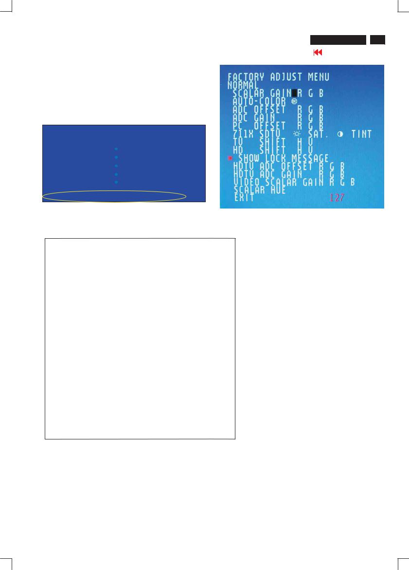
Apply" 100% Full White/100IRE" pattern by TV pattern generator. Alignment : Adjust the VIDEO SCALER GAIN R G B in Factory Mode
NORMAL . (See Fig 1.)
[ Enter factory menu : press Volume - and Volume + keys together
around six seconds] |
|
|
|
The 1931 CIE chromaticity |
(X, Y) co-ordinates shall be: |
||
|
Picture Mode |
X |
y |
|
|
|
|
|
Normal (Original) |
0.289 0.005 |
0.304 0.005 |
|
|
|
|
|
|
|
|
Table3.1: Readings with Minolta CA-110.

20 
 Magnavox LCD TV
Go to cover page
Electrical instruction
FACTORY ADJUST MENU
NORMAL
SCALER GAIN |
R G B |
|
|
||||
AUTO-COLOR (OK) |
|
|
|
||||
ADC OFFSET |
R G B |
|
|
|
|||
ADC GAIN |
R G B |
|
|
|
|||
PC OFFSET |
R G B |
|
|
||||
7119 SDTV |
|
SAT |
|
TINT |
|||
TV |
SHIFT |
H |
V |
|
|
|
|
HD |
SHIFT |
H |
V |
|
|
|
|
SHOW LOCK MESSAGE |
|
|
|||||
HDTV |
ADC OFFSET |
R |
G |
B |
|||
HDTV |
ADC GAIN |
R |
G |
B |
|||
VIDEO SCALER GAIN |
R |
G |
B |
||||
SCALER HUE |
|
|
|
|
|
||
EXIT |
|
|
|
Value |
|
|
|
Fig.1
4. PC mode display adjustment
4.1Display quality adjustment
Use timing mode as de scribe in 2.2, and use the POPO (pixel on pixel off) patternto adjust the clock until no stripe and adjust the phase until clear picture.(AUTO ADJUST hot key:press Volumeand Volume + keys togetherfor 1 second.)
Check all preset 4 modes.
4.2 WHITE-D adjustment (B)
4.2.1 At factory mode apply1024X768/60Hzmode with 64 gray pattern.
Set main controls Brightness at 50% and Contrast to 50%.
Select AUTO-COLOR function forADC OFFSETand ADC GAIN setup.
" "
4.2.2 Set smart picture as NORMAL
Set SCALER GAIN R G B= VIDEO SCALER GAIN R G B (alignment done).
The 1931 CIE chromaticity (X, Y) co-ordinates shall be:
Normal/ (8500 K)
(Or FLUKE 54200, apply576i, DIGITAL SCAN/DIGI_ADC1 pattern.)
Alignment method:
Initial Set-up : Set Smart picture as Personal, Brightness=50, Color=50, Contrast=50)Set AUTO-COLOR process.
Alignments :Check chromaticity (X, Y) co-ordinates specification:
Picture Mode |
If out of specification,fine-tune HDTV ADC Gainin factory mode. 6. Preset EEPROM data
6.1 EEPROM data has to be preset data according following table. Factory mode preset.
Function |
|
|
Preset value |
||||
SCALER GAIN |
|
127 |
127 |
127 |
|
||
ADC Offset R/G/B |
|
127 |
127 |
127 |
|
||
ADC Gain |
R/G/B |
|
127 |
127 |
127 |
|
|
PC OFFset R/G/B |
|
127 |
127 |
127 |
|
||
7119 |
? |
brightness |
124 |
(TV,AV,S-video,HD) |
|||
7119 |
|
Saturation |
64 |
(TV,AV,S-video,HD) |
|||
7119 |
|
contrast |
70 |
(TV,AV,S-video,HD) |
|||
|
|
|
|
|
|
||
7119 |
TINT |
24 |
(TV,AV,S-video,HD) |
||||
|
|
|
|
NTSC |
|
PAL |
|
|
|
|
|
|
|
||
TV shift H |
Regular |
|
170 |
|
181 |
||
TV shift V |
|
|
|
|
|
|
|
|
|
|
|
|
|
|
|
HD SHIFT H
HD SHIFT V
HD ADC OFFset R G B
HD ADC GAIN R G B
Video Scaler Gain
Scaler Hue
Readings with Minolta CA- |
110. |
Factory mode: |
|
|
|
||
4.2.3 Set Smart picture as WARM , and COOL The |
|
|
|
SCALER GAIN RG B = |
|
|
|
|
|
|
|
. |
|
|
|
|
Normal/ the R’\G’\B’ are |
WARM |
COOL |
|
gain after alignment. |
|
|
|
' |
' |
' |
|
' |
' |
' |
|
' |
' |
' |
4.3 Check the analog interface cable
Check the color poor & noise condition of 64 gray pattern.
5. HDTV mode display adjust ment
5.1 White balance adjustment (B) General set-up:
Equipment
In user Picture alignment
6.2 Smart picture &Smart sound: 6.2.1 Final TV mode out box setting. Smart Picture : Sport
Smart Picture |
Smart Sound : Personal SOUND VOLUME : 15 BASE : 50
TREBLE : 50
Balance : 0
Virtuel SURROUND: OFF AVL : NO
|
Electrical instruction |
Magnavox LCD TV |
|
21 |
||||||
|
|
|
|
|
|
|
|
Go to cover page |
||
|
|
|
|
|
|
|
|
|||
|
|
Smart sound |
|
|
|
|
|
|||
|
|
|
|
|
|
|
|
|
|
|
|
|
|
|
|
|
|
|
|
|
|
|
|
|
|
|
|
|
|
|
|
|
|
|
|
|
|
|
|
|
|
|
|
|
|
|
|
|
|
|
|
|
|
|
|
|
|
|
|
|
|
|
|
|
|
|
|
|
|
|
|
|
|
|
|
|
|
|
|
|
|
|
|
|
|
|
|
|
|
|
|
|
|
|
|
|
|
|
|
|
|
|
|
|
|
|
|
|
|
|
|
|
|
|
|
|
|
|
|
|
|
|
|
|
|
|
|
|
|
|
|
|
|
|
|
|
|
|
|
|
|
|
|
|
|
|
|
|
|
|
|
|
|
|
|
|
|
|
|
|
|
|
|
|
|
|
|
|
|
|
|
|
|
|
|
|
|
|
|
|
|
|
|
|
|
|
|
|
|
|
|
|
|
|
|
|
|
|
|
|
|
|
|
|
|
|
|
|
|
|
|
|
|
|
|
|
|
|
|
|
|
|
|
|
|
|
|
|
|
|
|
|
|
|
|
|
|
|
|
|
|
|
|
|
|
|
|
|
|
|
|
|
|
|
|
|
|
|
|
|
|
|
|
|
|
|
|
|
|
|
|
|
|
|
|
|
|
|
|
|
|
|
|
|
|
TIMING FOR F1 15" TFT XGA COLOR LCD MONITOR (VESA monitor timing standard Version 1.0 Release 0.7)
REFERENCE PATTERN GENERATOR : CHROMA 2200 or2250
TABLE 1: 31.469 KHz/70.087Hz, 640 X 350, pixel=25.175 MHz
|
Horizontal |
Vertical |
|
||
|
Frame border=0 |
Frame border=0 |
|
||
|
||
|
Total size =31.778 s |
Total size =14.268 ms |
|
||
|
||
|
Display size=25.422 s |
Display size=11.122 ms |
|
||
|
Rear porch= 1.907 s |
Rear porch= 1.907 ms |
|
Sync width= 3.813 s |
Sync width= 0.064 ms |
|
Sync polarity= |
Sync polarity= |
TABLE 2: 31.469 KHz/70.087Hz, 7 20 X 400, pixel=28.322 MHz
|
Horizontal |
Vertical |
|
|
Frame border=0 |
Frame border= |
0 |
|
|||
|
|||
|
Total size =31.778 s |
Total size =14.268 ms |
|
|
|||
|
|||
|
Display size=25.422 s |
Display size=12.711 ms |
|
|
|||
|
Rear porch= 1.907 s |
Rear porch= 1.112 ms |
|
|
|||
|
Sync width= 3.813 s |
Sync width= 0.064 ms |
|
|
|||
|
Sync polarity= |
Sync polarity=+ |
|
|
|
||
|
|
|
|
TABLE 3: 31.469 KHz/59.940Hz, 640 X 480, pixel=25.175 MHz
Horizontal |
Vertical |
Frame border=0 |
Frame border=0 |
Total size =31.778 s |
Total size =16.683 ms |
Display size=25.422 s |
Display size=15.253 ms |
Rear porch= 1.907 s |
Rear porch= 1.049 ms |
Sync width= 3.813 s |
Sync width= 0.064 ms |
Sync polarity= |
Sync polarity= |
TABLE 4: 35.000 KHz/66..667Hz, 640 X 480, pixel=30.240 MHz
Horizontal |
Vertical |
Frame border=0 |
Frame border=0 |
Total size =28.571 s |
Total size =15.000 ms |
Display size=21.164 s |
Display size=13.714 ms |
Rear porch= 3.175 s |
Rear porch= 1.114 ms |
Sync width= 2.116 s |
Sync width= 0.086 ms |
Sync polarity= |
Sync polarity= |

22 
 Magnavox LCD TV
Go to cover page
Electrical instruction
TABLE 5: 37.500 KHz/75.000Hz, 640 X 480, pixel=31.500 MHz
Horizontal Vertical
Frame border=0 Total size =26.667 s
Display size=20.317 s Rear porch= 3.810 s Sync width= 2.032 s Sync polarity=
Frame border=0 Total size =13.333 ms
Display size=12.800 ms Rear porch= 0.427 ms Sync width= 0.080 ms Sync polarity=
TABLE 6: 35.156 KHz/56.250Hz, 800 X 600, pixel=36.000 MHz
Horizontal Vertical
Frame border=0 Total size =28.444 s
Display size=22.222 s Rear porch= 3.556 s Sync width= 2.000 s Sync polarity=
Frame border=0 Total size =17.778 ms
Display size=17.067 ms Rear porch= 0.626 ms Sync width= 0.057 ms Sync polarity=
TABLE 10: 48.363 KHz/60.004Hz, 1024 X 768, pixel=65.000 MHz
Horizontal Vertical
Frame border=0 Total size =20.677 s
Display size=15.754 s Rear porch= 2.462 s Sync width= 2.092 s Sync polarity=
Frame border=0 Total size =16.666 ms
Display size=15.880 ms Rear porch= 0.600 ms Sync width= 0.124 ms Sync polarity=
TABLE 11: 60.023 KHz/75.029Hz, 1024 X 768, pixel=78.750 MHz
Horizontal Vertical
Frame border=0 Total size =16.660 s
Display size=13.003 s Rear porch= 2.235 s Sync width= 1.219 s Sync polarity=
Frame border=0 Total size =13.328 ms
Display size=12.795 ms Rear porch= 0.466 ms Sync width= 0.050 ms Sync polarity=
TABLE 7: 37.879 KHz/60.317Hz, 800 X 600, pixel=40.000 MHz
Horizontal Vertical
Frame border=0 Total size =26.400 s
Display size=20.000 s Rear porch= 2.200 s Sync width= 3.200 s Sync polarity=
Frame border=0 Total size =16.579 ms
Display size=15.840 ms Rear porch= 0.607 ms Sync width= 0.106 ms Sync polarity=
TABLE 8: 46.875 KHz/75.000Hz, 800 X 600, pixel=49.500 MHz
Horizontal Vertical
Frame border=0 Total size =21.333 s
Display size=16.162 s Rear porch= 3.232 s Sync width= 1.616 s Sync polarity=
Frame border=0 Total size =13.333 ms
Display size=12.800 ms Rear porch= 0.448 ms Sync width= 0.064 ms Sync polarity=
TABLE 9: 49.722 KHz/74.546Hz, 832 X 624, pixel=57.280 MHz
Horizontal Vertical
Frame border=0 Total size =20.110 s
Display size=14.520 s Rear porch= 3.910 s Sync width= 1.117 s Sync polarity=
Frame border=0 Total size =13.410 ms
Display size=12.550 ms Rear porch= 0.784 ms Sync width= 0.060 ms Sync polarity=

Display adjustment
Magnavox LCD TV 
 23
23
Go to cover page
Display adjustment
Access factory. Mode
how to get into factory mode menu
Step 1 : Select the source "PC" and then turn off LCD-TV.
Step 2 : [Push "power " button and then push the "VOL- " and "VOL+" buttons at the same time immediately and hold it] about five seconds then release all buttons.
Press "menu"button and bring up factory mode indication as shown in
Fig.1
MAIN CONTROLS |
1024X768@60HZ |
|
|
PICTURE |
SMART PICTURE |
AUDIO |
BRIGHTNESS |
FEATURES |
CONTRAST |
INSTALL |
AUTO ADJUST |
|
MANUAL ADJUST |
F1/FL1 NAFTA V1.01.05 041208 LG15XGA
Fig. 1
Use the CHNNELand CHNNEL+ to select the "F1/FL1 NAFTA V1.01. 05 041208 LG15XGA" and then press the "VOL +" button
Fig.2
PC mode WHITE-D adjustment (B)
1 Apply 1024X768/60Hz mode with 5 block pattern as Fig 3. Set main controls brightness control at 50% and contrast to 50% on
User mode. Set color setting at natural color on User mode. Move cursor to "AUTO-color" item on factory mode, press "menu" key to active this function, then scaler will adjust RGB and Color
RGB automatically by it self.
Fig.3
2. Apply a 1024x768/60Hz signal with white pattern.Set brightness control at 50% and contrast control at 50%. Adjust the
R.G.B gain to reach special color temperature on center of screen.
2.1 Aim the probe CA-A30 at the center of screen as Fig. 4
2.2 Remove the lens protective cover of probe CA-A30.
2.3 Set Measuring/viewing selector to Measuring position for reset analyzer. (Zero calibration) as Fig. 5
2.4 Turn on the colour analyzer (CA-110).
2.5 Press 0-CAL button to start reset analyzer. See Fig. 6
Cover (black)
Measurement viewing selector
Fig.4
Fig.5
O-CAL
Fig.6
2.6 Switch light probe to Viewing position.
2.7 Move the Lens barrel forward or backward to get clear image as shown in Fig. 7
2.8 Switch light probe to Measuring position. It should be able to indicate colour value on the CA-110.
 Clear image
Measurement/viewing selector
Fig.7

24 
 Magnavox LCD TV
Go to cover page
Display Adjustment
2.9 Set smart picture as" NORMAL"
Set SCALER GAIN R G B = VIDEO SCALER GAIN R G B(alignment done).
The 1931 CIE chromaticity (X, Y) co-ordinates shall be:
|
Normal/ (8500 K) |
x (center) |
0.289 0.030 |
y (center) |
0.304 0.030 |
Readings with Minolta CA-110.
2.10 Set Smart picture as" WARM", and "COOL" The SCALER GAIN R G B =
.
|
Normal/ the R'\G' \B' are |
WARM |
COOL |
|
gain after alignment. |
|
|
R gain |
R' |
R ' |
R'-10 |
G gain |
G' |
G'-10 |
G'-10 |
B gain |
B ' |
B '-10 |
B ' |

DDC DATA |
|
|
|
Magnavox LCD TV |
|
25 |
|
LPL panel:
**********************************************************************
EDID log file
**********************************************************************
Vendor/Product Identification |
|
|
|
ID Manufacturer Name |
: PHL |
||
ID Product Code |
|
: 4650 (HEX.) |
|
ID Serial Number |
|
: 1010101 (HEX.) |
|
Week of Manufacture |
|
: 0 |
|
Year of Manufacture |
|
: |
2004 |
EDID Version, Revision |
|
|
|
Version |
: |
1 |
|
Revision |
: |
3 |
|
Basic Display Parameters/Features |
|
||
Video Input Definition |
|
: Analog Video Input |
|
|
0.700V/0.300V (1.00Vpp) |
||
|
without Blank-to-Black Setup |
||
|
Separate Sync |
||
|
without Composite Sync |
||
|
without Sync on Green |
||
|
no Serration required |
||
Maximum H Image Size |
: 30 |
||
Maximum V Image Size |
: 23 |
||
Display Transfer Characteristic : 2.2 |
|||
(gamma) |
|
|
|
Feature Support (DPMS) |
: Standby |
||
|
|
|
Suspend |
|
|
|
Active Off |
Display Type |
|
: RGB color display |
|
Standard Default Color Space |
: Primary color space |
||
Preferred Timing Mode |
: |
Detailed timing block 1 |
|
|
|
|
Go to cover page |
Monitor Descriptor #4 |
|
|
|
Monitor Range Limits |
|
|
|
Min. Vt rate Hz |
|
: |
58 |
Max. Vt rate Hz |
|
: |
62 |
Min. Horiz. rate kHz |
: |
30 |
|
Max. Horiz. rate kHz |
: |
49 |
|
Max. Supported Pixel |
: 70 |
|
|
No secondary GTF timing formula supported. |
|||
Extension Flag |
: 0 |
|
|
Check sum |
|
: F8 (HEX.) |
|
**********************************************************************
EDID data (128 bytes)
**********************************************************************
0: 00 |
1: ff |
2: ff |
3: ff |
4: ff |
5: ff |
6: ff |
|
7: 00 |
8: 41 |
9: 0c |
10: 50 |
11: 46 |
12: 01 |
13: 01 |
14: 01 |
15: 01 |
|
16: 00 |
17: 0e |
18: 01 |
19: 03 |
20: 08 |
21: 1e |
22: 17 |
|
23: 78 |
24: ee |
25: b4 |
26: 43 |
27: 9e |
28: 57 |
29: 4c |
30: 94 |
|
31: 26 |
32: 15 |
33: 4a |
34: 4d |
35: 23 |
36: 08 |
37: 00 |
38: 01 |
|
39: 01 |
40: 01 |
41: 01 |
42: 01 |
43: 01 |
44: 01 |
45: 01 |
46: 01 |
|
47: 01 |
48: 01 |
49: 01 |
50: 01 |
51: 01 |
52: 01 |
53: 01 |
54: 00 |
|
55: 00 |
56: 00 |
57: ff |
58: 00 |
59: 0a |
60: 20 |
61: 20 |
62: 20 |
|
63: 20 |
64: 20 |
65: 20 |
66: 20 |
67: 20 |
68: 20 |
69: 20 |
70: 20 |
|
71: 20 |
72: 00 |
73: 00 |
74: 00 |
75: ff |
76: 00 |
77: 0a |
78: 20 |
|
79: 20 |
80: 20 |
81: 20 |
82: 20 |
83: 20 |
84: 20 |
85: 20 |
86: 20 |
|
87: 20 |
88: 20 |
89: 20 |
90: 00 |
91: 00 |
92: 00 |
93: fc |
94: 00 |
|
95: 50 |
96: 68 |
97: 69 |
98: 6c |
99: 69 |
100: 70 |
101: 73 102: 20 103: 46 |
|||
104: 31 105: 20 |
106: 31 107: 35 108: 00 |
109: 00 |
110: 00 |
111: fd |
||||
112: 00 113: 3a |
114: 3e 115: 1e 116: 31 |
117: 07 |
118: 00 |
119: 0a |
||||
120: 20 121: 20 |
122: 20 123: 20 124: 20 125: 20 |
126: 00 |
|
127: f8 |
||||
Color Characteristics |
|
|
|
Red |
X coordinate |
: |
0.619 |
Red |
Y coordinate |
: |
0.343 |
Green X coordinate |
: |
0.298 |
|
Green Y coordinate |
: |
0.578 |
|
Blue |
X coordinate |
: |
0.149 |
Blue |
Y coordinate |
: |
0.082 |
White X coordinate |
: |
0.289 |
|
White Y coordinate |
: |
0.304 |
|
Established Timings |
|
|
|
Established Timings I |
|
: 640 x 480 @60Hz (IBM,VGA) |
|
|
|
|
800 x 600 @56Hz (VESA) |
|
|
|
800 x 600 @60Hz (VESA) |
Established Timings II |
: 1024 x 768 @60Hz (VESA) |
||
Manufacturer's timings |
|
: |
|
Standard Timing Identification |
: Unused |
||
Monitor Descriptor #1 |
|
|
|
Serial Number |
: |
|
|
Monitor Descriptor #2 |
|
|
|
Serial Number |
: |
|
|
Monitor Descriptor #3 |
|
|
|
Monitor Name |
: Philips F1 15 |
||

26 
 Magnavox LCD TV
Go to cover page
DDC DATA
AUO panel:
**********************************************************************
EDID log file
**********************************************************************
Vendor/Product Identification |
|
|
ID Manufacturer Name |
: PHL |
|
ID Product Code |
|
: 4650 (HEX.) |
ID Serial Number |
|
: 1010101 (HEX.) |
Week of Manufacture |
|
: 0 |
Year of Manufacture |
|
: 2004 |
EDID Version, Revision |
|
|
Version |
: |
1 |
Revision |
: |
3 |
Basic Display Parameters/Features
Video Input Definition : Analog Video Input 0.700V/0.300V (1.00Vpp) without Blank-to-Black Setup Separate Sync
without Composite Sync without Sync on Green no Serration required
Maximum H Image Size |
|
: 30 |
|
Maximum V Image Size |
|
: 23 |
|
Display Transfer Characteristic : 2.4 |
|||
|
(gamma) |
|
|
Feature Support (DPMS) |
|
: Standby |
|
|
|
|
Suspend |
|
|
|
Active Off |
Display Type |
|
: RGB color display |
|
Standard Default Color Space : Primary color space |
|||
Preferred Timing Mode |
|
: Detailed timing block 1 |
|
Color Characteristics |
|
|
|
Red |
X coordinate |
: 0.604 |
|
Red |
Y coordinate |
: 0.347 |
|
Green X coordinate |
|
: 0.283 |
|
Green Y coordinate |
|
: 0.583 |
|
Blue X coordinate |
: |
0.147 |
|
Blue Y coordinate |
: |
0.088 |
|
White X coordinate |
|
: 0.279 |
|
White Y coordinate |
: 0.291 |
||
Monitor Descriptor #3 |
|
|
Monitor Name |
: Philips F1 15 |
|
Monitor Descriptor #4 |
|
|
Monitor Range Limits |
|
|
Min. Vt rate Hz |
|
: 58 |
Max. Vt rate Hz |
|
: 62 |
Min. Horiz. rate kHz |
: |
30 |
Max. Horiz.rate kHz |
: |
49 |
Max. Supported Pixel |
: 70 |
|
No secondary GTF timing formula supported.
Extension Flag |
: 0 |
Check sum |
: 44 (HEX.) |
*******************************************************************
EDID data (128 bytes)
**********************************************************************
0: 00 |
1: ff 2: ff |
|
3: ff |
|
4: ff |
5: ff |
6: ff |
7: 00 |
||
8: 41 |
9: 0c |
10: 50 |
|
11: 46 |
12: 01 |
13: 01 |
14: 01 |
15: |
01 |
|
16: 00 |
17: 0e |
18: 01 19: 03 |
|
20: 08 |
21: 1e |
22: 17 |
23: 8c |
|||
24: ee |
25: b9 |
26: ea |
27: 9a |
28: 58 |
29: 48 |
30: 95 |
31: 25 |
|||
32: 16 |
33: 47 |
34: 4a |
35: 23 |
36: 08 |
37: 00 |
38: 01 |
39: 01 |
|||
40: 01 |
41: 01 |
42: 01 |
|
43: 01 |
44: 01 |
45: 01 |
46: 01 |
4 7: 01 |
||
48: 01 |
49: 01 |
50: 01 |
51: 01 |
52: 01 |
53: 01 |
54: 00 |
55: 00 |
|||
56: 00 |
57: ff |
58: 00 |
59: 0a |
60: 20 |
61: 20 |
62: 20 |
63: 20 |
|||
64: 20 |
65: 20 |
66: 20 |
67: 20 |
68: 20 |
69: 20 |
70: 20 |
71: 20 |
|||
72: 00 |
73: 00 |
74: 00 |
75: ff |
|
76: 00 |
77: 0a |
78: 20 |
79: 20 |
||
80: 20 |
81: 20 |
82: 20 |
83: 20 |
84: 20 |
85: 20 |
86: 20 |
87: 20 |
|||
88: 20 89: 20 |
90: 00 |
91: 00 |
92: 00 |
93: fc |
94: 00 |
95: 50 |
||||
96: 68 |
97: 69 |
98: 6c |
99: 69 |
100: 70 |
101: 73 102: 20 |
103: 46 |
||
104: 31 |
105: 20 106: 31 |
107: 35 |
108: 00 |
109: 00 |
110: 00 |
111: fd |
||
112: 00 113: 3a 114: 3e |
115: 1e |
116: 31 |
117: 07 |
118: 00 |
119: 0a |
|||
120: 20 |
121: 20 122: 20 123: 20 |
124: 20 |
125: 20 |
126: 00 |
127: 44 |
|||
Established Timings |
|
Established Timings I |
: 640 x 480 @60Hz (IBM,VGA) |
|
800 x 600 @56Hz (VESA) |
|
800 x 600 @60Hz (VESA) |
Established Timings II |
: 1024 x 768 @60Hz (VESA) |
Manufacturer's timings |
: |
Standard Timing Identification |
: Unused |
Monitor Descriptor #1 |
|
Serial Number |
: |
Monitor Descriptor #2 |
|
Serial Number |
: |

DDC DATA
Magnavox LCD TV 27
Go to cover page
9.3 CPT panel:
**********************************************************************
EDID log file
**********************************************************************
Vendor/Product Identification |
|
|
|
|
|
ID Manufacturer Name |
|
|
: PHL |
||
ID Product Code |
|
|
|
: 4650 (HEX.) |
|
ID Serial Number |
|
|
: 1010101 (HEX.) |
||
Week of Manufacture |
|
|
: 0 |
||
Year of Manufacture |
|
|
: |
2004 |
|
EDID Version, Revision |
|
|
|
|
|
Version |
: |
1 |
|
|
|
Revision |
: |
3 |
|
|
|
Basic Display Parameters/Features |
|
|
|||
Video Input Definition |
|
: Analog Video Input |
|||
|
|
0.700V/0.300V (1.00Vpp) |
|||
|
|
without Blank-to-Black Setup |
|||
|
|
Separate Sync |
|||
|
|
without Composite Sync |
|||
|
|
without Sync on Green |
|||
|
|
no Serration required |
|||
Maximum H Image Size |
|
|
: 30 |
||
Maximum V Image Size |
|
|
: 23 |
||
Display Transfer Characteristic : 2.3 |
|||||
|
(gamma) |
|
|
|
|
Feature Support (DPMS) |
|
|
: Standby |
||
|
|
|
|
|
Suspend |
|
|
|
|
|
Active Off |
Display Type |
|
|
|
: RGB color display |
|
Standard Default Color Space |
: Primary color space |
||||
Preferred Timing Mode |
|
|
: Detailed timing block 1 |
||
Color Characteristics |
|
|
|
|
|
Red |
X coordinate |
|
: |
0.643 |
|
Red |
Y coordinate |
|
: |
0.335 |
|
Green X coordinate |
|
: |
0.297 |
||
Green Y coordinate |
|
: |
0.588 |
||
Blue |
X coordinate |
|
: |
0.142 |
|
Blue |
Y coordinate |
|
: |
0.078 |
|
White X coordinate |
|
: |
0.313 |
||
White Y coordinate |
|
: |
0.329 |
||
Established Timings |
|
|
|
|
|
Established Timings I |
|
|
: 640 x 480 @60Hz (IBM,VGA) |
||
|
|
|
|
|
800 x 600 @56Hz (VESA) |
|
|
|
|
|
800 x 600 @60Hz (VESA) |
Established Timings II |
|
: 1024 x 768 @60Hz (VESA) |
|||
Manufacturer's timings |
|
: |
|
||
Standard Timing Identification |
|
: Unused |
|||
Monitor Descriptor #1 |
|
|
|
|
|
Serial Number |
|
: |
|
|
|
Monitor Descriptor #2 |
|
|
|
|
|
Serial Number |
|
: |
|
|
|
Monitor Name |
|
|
|
: Philips F1 15 |
|
|
|
|
|
|
||||
Monitor Descriptor #4 |
|
|
|
|
|
|
|
|
|
|
|
|||
Monitor Range Limits |
|
|
|
|
|
|
|
|
|
|||||
Min. Vt rate Hz |
|
|
|
|
|
|
: 58 |
|
|
|
|
|||
Max. Vt rate Hz |
|
|
|
|
|
: |
62 |
|
|
|
|
|||
Min. Horiz. rate kHz |
|
|
: 30 |
|
|
|
|
|
||||||
Max. Horiz. rate kHz |
|
|
: |
49 |
|
|
|
|
||||||
Max. Supported Pixel |
|
|
: 70 |
|
|
|
|
|
|
|||||
No secondary GTF timing formula supported. |
|
|
|
|||||||||||
Extension Flag |
|
|
|
|
: |
0 |
|
|
|
|
|
|
||
Check sum |
|
|
|
|
|
|
|
: DE (HEX.) |
|
|
||||
********************************************************************** |
|
|||||||||||||
EDID data (128 bytes) |
|
|
|
|
|
|
|
|
|
|
|
|||
********************************************************************** |
|
|||||||||||||
0: 00 |
1: ff |
|
2: ff |
|
3: ff |
|
|
4: ff |
5: ff |
6: ff |
7: 00 |
|||
8: 41 |
9: 0c |
|
10: 50 |
11: 46 |
12: 01 |
13: 01 |
14: 01 |
15: 01 |
||||||
16: 00 |
17: 0e |
|
18: 01 |
|
19: 03 |
20: 08 |
21: 1e |
|
22: 17 |
23: 82 |
||||
24: ee |
25: b2 |
|
26: 45 |
|
27: a4 |
|
28: 55 |
29: 4c |
|
30: 96 |
31: 24 |
|||
32: 14 |
33: 50 |
34: 54 |
|
35: 23 |
36: 08 |
37: 00 |
|
38: 01 |
39: 01 |
|||||
40: 01 |
41: 01 |
|
42: 01 |
|
43: 01 |
44: 01 |
|
45: 01 |
|
46: 01 |
47: 01 |
|||
48: 01 |
49: 01 |
|
50: 01 |
|
51: 01 |
52: 01 |
|
53: 01 |
54: 00 |
|
55: 00 |
|||
56: 00 |
57: ff |
|
58: 00 |
59: 0a |
60: 20 |
|
61: 20 |
62: 20 |
|
63: 20 |
||||
64: 20 |
65: 20 |
|
66: 20 |
67: 20 |
68: 20 |
|
69: 20 |
70: 20 |
|
71: 20 |
||||
72: 00 |
73: 00 |
|
74: 00 |
75: ff |
|
76: 00 |
|
77: 0a |
78: 20 |
|
79: 20 |
|||
80: 20 |
81: 20 |
|
82: 20 |
83: 20 |
84: 20 |
|
85: 20 |
86: 20 |
87: 20 |
|||||
88: 20 |
89: 20 |
|
90: 00 |
91: 00 |
92: 00 |
|
93: fc |
|
94: 00 |
95: 50 |
||||
96: 68 |
97: 69 |
|
98: 6c |
99: 69 |
100: 70 |
101: 73 |
102: 20 103: 46 |
|||||||
104: 31 105: 20 |
106: 31 107: 35 |
108: 00 |
109: 00 |
110: 00 111: fd |
||||||||||
112: 00 113: 3a |
114: 3e 115: 1e |
116: 31 |
117: 07 |
118: 00 119: 0a |
||||||||||
120: 20 121: 20 |
122: 20 123: 20 |
124: 20 |
125: 20 |
126: 00 127: de |
||||||||||
Monitor Descriptor #3
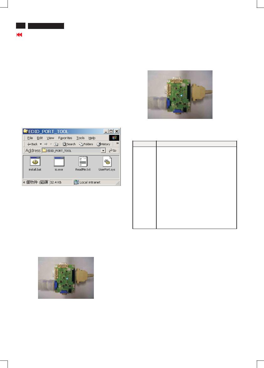
28 
 Magnavox LCD TV
DDC INSTRUCTIONS
Go to cover page
General
DDC Data Re-programming
In case the DDC data memory IC or main EEPROM which storage all factory settings were replaced due to a defect, the serial numbers have to be re-programmed"Analog DDC IC, & EEPROM".
It is advised to re-soldered DDC IC and main EEPROM from the old board onto the new board if circuit board have been replaced, in this case the DDC data does not need to be re-programmed.
Additional information
Additional information about DDC (Display Data Channel) may be obtained from Video Electronics Standards Association (VESA). Extended Display Identification Data(EDID) information may be also obtained from VESA.
System and equipment requirements
1. |
An i486 (or above) personal computer or compatible. |
|
2. |
Microsoft operation system Windows 95/98 . |
|
|
You have to Install the EDID_PORT_Tool |
under Win2000/XP . As |
|
Fig. 1 . |
Fig. 1 |
Note: The alignment box has already build-in a batteries socket for using batteries (8~12V) as power source. Pull out the socket by remove four screws at the rear of box. Please do not forget that remove batteries after programming. The energy of batteries can only drive circuits for a short period of time.
To Monitor |
To Printer port |
D-sub cable |
|
To PC |
Fig. 3 |
A. Cody the "UserPort.sys" to C:\WINNT\system32\drivers(win2000)
C:\WINDOWS\system32\drivers(winXP)
B.Running " io.exe" everytime, Before you start to programming edid data .
3.EDID45.EXE program .
4.A/D Alignment kits (3138 106 10396):
inclusion : a. Alignment box x1 (as Fig. 2)
Pin assignment
PIN No. SIGNAL
A. 15-pin D-Sub Connector
1Red
2Green
3Blue
4GND
5GND
6Red GND
7Green GND
8Blue GND
9+5V (Supply from PC) 10 Sync GND
11 |
GND |
12 |
Bi-directional data |
13H-sync
14V-sync
15Data clock
Fig. 2
b.Printer cable x1
c.(D-Sub) to (D-Sub) cable x1
 Loading...