


 Loading...
TV-VCR Combination
Service
Service
Service
14PV135/01/07/58 14PV235/01/07/58 14PV385/01/07/39
Service Manual
Contents |
Survey of versions: |
|
Chapter |
/01 |
PAL-BG, EURO |
|
/07 |
PAL I, UK/IRELAND |
Sec. 1: Adjustment Procedure |
/39 |
PAL/SECAM-BG+PAL/SECAM-L/L',FRANCE |
Schematic Diagrams and CBA's |
/58 |
PAL-BG/DK+SECAM-BG/DK,EAST-EURO |
Exploded Views
Mechanical and Electrical Parts Lists
Sec. 2: Standard Maintenance
Mechanism Alignment Procedures
Disassembly / Assembly of Mechanism
Deck Exploded Views
For technical data reference is made to the Service Manual of 21PV385/01/07/39/58 3103 785 22330 (VN: 1B). The present manual states only the differences.
Safety regulations require that the set be restored to its original condition and that parts which are identical with those specified be used.
Published by BK 2004 Video Service Department Printed in the Netherlands c Copyright reserved Subject to modification GB 3103 785 22310

PREPARATION FOR SERVICING
[ 14PV135/ (01, 07, 58), 14PV235/ (01, 07, 58), 14PV385/ (01, 07, 39) ]
How to Enter the Service Mode
Caution: 1
1.Optical sensors system are used for Tape Start and End Sensor on this equipment. Read this page carefully and prepare as described on this page before starting to service; otherwise, the unit may operate unexpectedly.
Preparing: 1
1.Cover Q202 (START SENSOR) and Q201 (END SENSOR) with Insulation Tape or enter the service mode to activate Sensor Inhibition automatically.
Note: Avoid playing, rewinding or fast forwarding the tape to its beginning or end, because both Tape End Sensors are not active.
How to Enter the Service Mode
1.Turn the power on. (Use main power on the TV unit.)
2.Press [STANDBY/ON], [2], [7], [1], and [MUTE] buttons on the remote control unit in that order within 5 seconds. When entering the service mode, “4” will display at corners of the screen.
3.During the service mode, electrical adjustment mode can be selected by remote control key.
Details are as follows.
Key |
Adjustment Mode |
Picture adjustment mode: Press the MENU button to change from BRT (Bright), *CNT (Contrast), *COL
MENU (Color), *TNT(Tint) and SHP(SHARP). Press P+/P- key to adjust Initial Value. *Marked items are not necessary to adjust normally.
SECAM Black Level adjustment mode: See adjustment instructions page 1-6-13.
 - Cut-Off adjustment mode: See adjustment instructions page 1-6-14.
White Balance adjustment mode: See adjustment instructions page 1-6-15.
0
C-Trap adjustment mode: See adjustment instructions page 1-6-12.
1
DSPC adjustment mode: See adjustment instructions page 1-6-12.
2
H adjustment mode: See adjustment instructions page 1-6-11.
Head switching point adjustment mode
3(Auto adjustment): See adjustment instructions page 1-6-17.
Auto record mode: Perform recording
4(15 Sec.)-->Stop-->Rewind (Zero return) automatically.
Key |
Adjustment Mode |
|
|
|
|
5 |
Head switching point adjustment mode |
|
(Manual adjustment): See adjustment |
||
|
instructions page 1-6-17. |
|
|
|
|
6 |
No need to use. |
|
|
|
|
7 |
No need to use. |
|
|
|
|
8 |
H. Shift adjustment mode: See adjust- |
|
ment instructions page 1-6-14. |
||
|
||
|
|
|
9 |
V.size/V. shift adjustment: See adjust- |
|
ment instructions page 1-6-13. |
||
|
||
|
|
|
Caution: 2 |
|
1.The deck mechanism assembly is mounted on the Main CBA directly, and SW211 (REC-SAFETY SW) is mounted on the Main CBA. When deck mechanism assembly is removed from the Main CBA due to servicing, this switch can not be operated automatically.
Preparing: 2
1.To eject the tape, press the STOP/EJECT button on the unit (or Remote Control).
2.When you want to record during the Service mode, press the Rec button while depressing SW211 (REC-SAFETY SW) on the Main CBA.
Q201 |
Q202 |
(END SENSOR) |
(START SENSOR) |
SW211
(REC-SAFETY SW) |
MAIN CBA |
|
1-3-2 |
T6450PFS |

OPERATING CONTROLS AND FUNCTIONS
[ 14PV135/ (01, 07, 58), 14PV235/ (01, 07, 58) ]
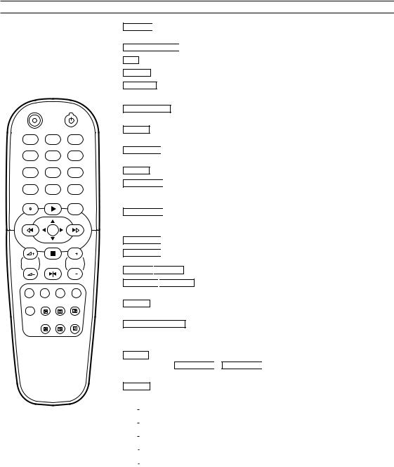
The remote control
REC STANDBY/ON
1 |
2 |
3 |
4 |
5 |
6 |
7 |
8 |
9 |
SLEEP |
|
SYSTEM |
|
0 |
|
STATUS/EXIT |
PLAY |
CLEAR |
REW |
|
FWD |
|
MENU |
|
|
STOP |
|
|
|
P |
VOL |
STILL |
PROG |
|
|
|
|
|
P |
MUTE |
|
|
REC 
 To record the TV channel selected at this moment or press repeatedly to start a One-Touch Recording.
STANDBY/ON 
 To switch off or on, interrupt menu function.
0..9 Press to select channels at TVCR.
SLEEP To select the switch-off time in 30 minutes intervals.
SYSTEM Doesn’t work on this models. (14PV135/01, 07 / 14PV235/01, 07)
To change Video (colour) system. (14PV135/58 / 14PV235/58)
STATUS/EXIT To access or remove the TVCR’s on-screen status display. To exit on-screen
menus.
CLEAR To delete last entry. To clear a programmed recording (TIMER). To reset the elapsed time counter in the playback, recording or stop mode.
STILL 
 To stop the tape and play back a picture step by step. (except for during fast forwarding and fast rewinding)
MENU To call up main menu of TVCR.
FWD  -
-  When tape playback is stopped, press to fast forward the tape at high speed. During playback, press to fast forward the tape while the picture stays on the screen. To store or confirm entry in the menu. Press to adjust the controls of TVCR menu.
REW -
- 
 When tape playback is stopped, press to rewind the tape at high speed. During playback, press to rewind the tape while the picture stays on the screen.To return the cursor in the menu. Press to adjust the controls of TVCR menu.
PLAY  -
- 
 To play back a tape, select an item in the menu of TVCR.
STOP  -
- 
 To stop the tape, select an item in the menu of TVCR.
VOL +
+ 
 VOL
VOL – To adjust the volume.
PROG P+ 
 PROG P– To select the programme number. During playback, press to adjust the tracking.
MUTE To eliminate the TV’s sound. Press again to restore the volume.
Red button/ Green button/ Yellow button/ Blue button/ Doesn’t work on these models.
<14PV235>
 : To switch Teletext on or off, or transparent mode.
 : Enlarge font
 : Select Teletext sub-page
 : Recall hidden information
 : Stop page changes
 : Go back to start page.
1-4-3 |
T6450IB |

Front of your TVCR
VIDEO AUDIO
P
STANDBY/ ON
|
STANDBY/ON: To switch off or on, interrupt menu function. |
|
Volume: In connection with the button + – to adjust the volume. |
P+ |
P- Programme number: To select the programme number. During playback, press to adjust the |
tracking. To remove vertical jitter in a Still picture.


 Record: To record the programme currently selected.
Playback: To play a recorded cassette.


 Pause/ Stop, eject cassette: To stop the tape; If this key is depressed while in STOP, the cassette is then ejected from the machine.


 When tape playback is stopped, press to fast forward the tape at hight speed.


 When tape playback is stoped, press to rewind the tape at hight speed.


 Sockets on the front:
White socket / AUDIO input socket: To connect a camcorder or a video game machine (audio).
Yellow socket / VIDEO input socket: To connect a camcorder or a video game machine (video).
Small socket / 

 socket for headphones: To connect headphones.
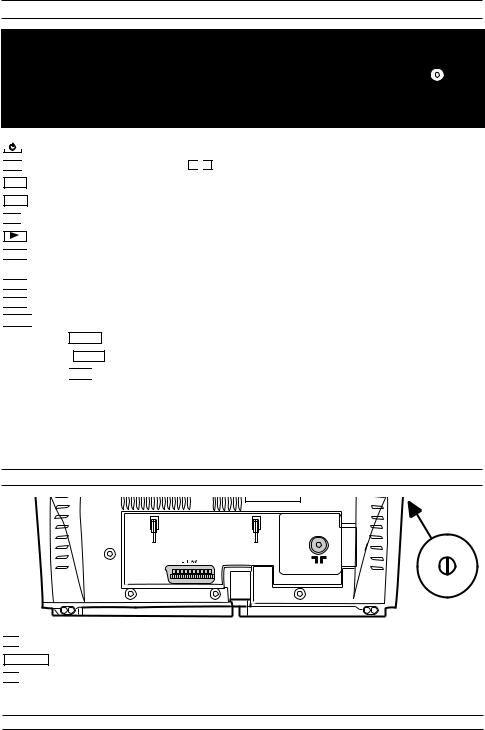
Back of your TVCR


 Aerial input socket: To connect the aerial cable.
EXT1/AV Scart socket :To connect a satellite receiver, decoder, video recorder, etc


 Power switch: To switch the TV-Video Combi off.
Caution: If you switch off using the power switch, TIMER-recordings are impossible!
The control lights on the front of machine
STANDBY  Standby light: lights up when the TV-Video Combi has been switched on by means of the main switch.
RECORD  Recording light: lights up during recording.
FAST blink: RECORDING PAUSE; TIMER RECORDING NOT STAND-BY.
SLOW blink: TIMER RECORDING is stored in a timer block.
1-4-4 |
T6450IB |
[ 14PV385/ (01, 07, 39) ]
The remote control
REC STANDBY/ON
1 |
2 |
3 |
4 |
5 |
6 |
7 |
8 |
9 |
SLEEP |
|
SYSTEM |
|
0 |
|
STATUS/EXIT |
PLAY |
CLEAR |
REW |
|
FWD |
|
MENU |
|
|
STOP |
|
|
|
P |
VOL |
STILL |
PROG |
|
|
|
|
|
P |
SV/V+ SMART PICTURE |
INDEX |
|
MUTE |
|
|
REC 
 To record the TV channel selected at this moment or press repeatedly to start a One-Touch Recording.
STANDBY/ON 
 To switch off or on, interrupt menu function.
0..9 Press to select channels at TVCR.
SLEEP To select the switch-off time in 30 minutes intervals.
SYSTEM Doesn’t work on this model. (14PV385/01, 07)
To change the Video (colour) system. (14PV385/39)
STATUS/EXIT To access or remove the TVCR’s on-screen status display. To exit on-screen
menus.
CLEAR To delete last entry. To clear a programmed recording (TIMER). To reset the elapsed time counter in the playback, recording or stop mode.
STILL 
 To stop the tape and play back a picture step by step. (except for during fast forwarding and fast rewinding)
MENU To call up main menu of TVCR.
FWD  -
-  When tape playback is stopped, press to fast forward the tape at high speed. During playback, press to fast forward the tape while the picture stays on the screen. To store or confirm entry in the menu. Press to adjust the controls of TVCR menu.
REW -
- 
 When tape playback is stopped, press to rewind the tape at high speed. During playback, press to rewind the tape while the picture stays on the screen.To return the cursor in the menu. Press to adjust the controls of TVCR menu.
PLAY  -
- 
 To play back a tape, select an item in the menu of TVCR.
STOP  -
- 
 To stop the tape, select an item in the menu of TVCR.
VOL +
+ 
 VOL
VOL – To adjust the volume.
PROG P+ 
 PROG P– To select the programme number. During playback, press to adjust the tracking.
SV/V+ Red button / To programme recordings with SHOW VIEW / VIDEO Plus+® or to alter / clear programmed TIMER recordings. Select Teletext function when you are in Teletext mode.
SMART PICTURE Green button / To call up preset picture settings.Select Teletext function when you are in Teletext mode.
Yellow button/ Select Teletext function when you are in Teletext mode.
INDEX Blue button / Search for the previous/next recording code on the tape in
combination with REW -
- 
 / FWD
/ FWD  -
-  . Select Teletext function when you are in Teletext mode.
MUTE To eliminate the TV’s sound. Press again to restore the volume.
 : Switch Teletext on or off, or transparent mode
 : Enlarge font
 : Select Teletext sub-page
 : Recall hidden information
 : Stop page changes
 : Go back to start page
1-4-5 |
T6450IB |
Front of your TVCR
VIDEO AUDIO
P
STANDBY/ON
STANDBY/ON: To switch off or on, interrupt menu function.


 Volume: In connection with the button +
 – to adjust the volume.
P- Programme number minus: previous programme number
P+ Programme number plus: next programme number


 Record: To record the programme currently selected.
Playback: To play a recorded cassette.

 /
/
 Pause/Stop, eject cassette: To stop the tape; If this key is depressed while in STOP, the cassette is then ejected from the machine.


 When tape playback is stopped, press to fast forward the tape at hight speed.


 When tape playback is stoped, press to rewind the tape at hight speed.


 Sockets on the front:
White socket / AUDIO input socket: To connect a camcorder or a video game machine (audio).
Yellow socket / VIDEO input socket: To connect a camcorder or a video game machine (video).
Small socket / 

 socket for headphones: To connect headphones.
Back of your TVCR


 Aerial input socket: To connect the aerial cable.
EXT1/AV Scart socket : To connect a satellite receiver, decoder, video recorder, etc


 Power switch: To switch the TVCR off.
Caution: If you switch off using the power switch, TIMER-recordings are impossible!
The control lights on the front of machine
STANDBY  Standby light: lights up when the TVCR has been switched on by means of the main switch.
RECORD  Recording light: lights up during recording.
FAST blink: RECORDING PAUSE; TIMER RECORDING NOT STAND-BY.
SLOW blink: TIMER RECORDING is stored in a timer block.
1-4-6 |
T6450IB |
CABINET DISASSEMBLY INSTRUCTIONS
[ 14PV135/ (01, 07, 58), 14PV235/ (01, 07, 58), 14PV385/ (01, 07, 39) ]
Comparison Chart of Models and Marks
Model |
Mark |
|
|
14PV135/07 |
E |
|
|
14PV235/07 |
F |
|
|
14PV385/07 |
G |
|
|
14PV135/01 |
H |
|
|
14PV235/01 |
I |
|
|
14PV385/01 |
J |
|
|
14PV135/58 |
K |
|
|
14PV235/58 |
L |
|
|
14PV385/39 |
M |
|
|
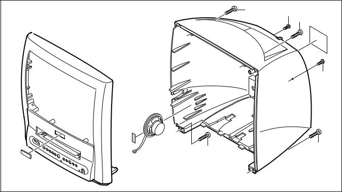
1. Disassembly Flowchart
This flowchart indicates the disassembly steps for the cabinet parts, and the CBA in order to gain access to item(s) to be serviced. When reassembling, follow the steps in reverse order. Bend, route and dress the cables as they were.
Caution !!
When removing the CRT, be sure to discharge the Anode Lead of the CRT with the CRT Ground Wire before removing the Anode Cap.
|
|
|
|
|
[1] Rear Cabinet |
|
|
|
|
|
|
|
|
|
|
|
|
|
|
|
|
|
|
|
||
|
|
[2] Power Unit and Tray Chassis Unit |
||||||
|
|
|
|
|
|
|
||
|
|
|
|
|
|
|
||
[5] H.V./Power |
|
|
|
[3] Power Unit |
|
|||
|
|
|
|
|
||||
Supply CBA |
|
|
|
|
|
|
|
|
|
|
|
|
|
|
|
||
|
|
|
|
|
[4] Tray Chassis Unit |
|
||
|
|
|
|
|
|
|
|
|
|
|
|
|
|
|
|
|
|
|
|
|
|
|
[6] Top Cover |
|
||
|
|
|
|
|
|
|
|
|
|
|
|
|
|
|
|
|
|
|
|
|
|
|
[7] Bottom Plate |
|
||
|
|
|
|
|
|
|
|
|
|
|
|
|
|
|
|
|
|
|
|
|
|
|
[8] Deck Unit |
|
||
|
|
|
|
|
|
|
|
|
|
|
|
|
|
|
|
||
|
|
|
|
[9] Text CBA [ F,G,I,J,L,M ] |
|
|||
|
|
|
|
|
|
|
||
|
|
|
|
|
|
|
||
|
|
|
|
|
[10] Main CBA |
|
||
|
|
|
|
|
|
|
||
|
|
|
|
|
|
|
||
|
|
|
|
|
[11] CRT |
|
||
|
|
|
|
|
|
|
|
|
2. Disassembly Method
|
|
|
REMOVAL |
|
||
|
|
|
|
|
||
ID/ |
|
|
REMOVE/ |
|
||
|
|
*UNHOOK/ |
|
|||
LOC. |
PART |
Fig. |
|
|||
UNLOCK/RELEASE/ |
Note |
|||||
No. |
|
|||||
|
No. |
UNPLUG/DESOL- |
|
|||
|
|
|
||||
|
|
|
DER |
|
|
|
|
|
|
|
|
||
|
|
|
|
|
||
[1] |
Rear |
1,2,5 |
4(S-1), 2(S-2), |
1 |
||
Cabinet |
*CN804 |
|
||||
|
|
|
|
|
|
|
|
Power Unit |
|
Anode Cap, *CN501, |
|
||
|
and Tray |
|
|
|||
[2] |
3,4,5 |
*CN551, *CN601, |
2 |
|||
Chassis |
||||||
|
|
CRT CBA |
|
|||
|
Unit |
|
|
|||
|
|
|
|
|
||
|
|
|
|
|
|
|
[3] |
Power Unit |
3,5 |
*CN502, |
*CN552, |
3 |
|
*CN602 |
|
|||||
|
|
|
|
|
||
|
|
|
|
|
|
|
|
Tray |
|
|
|
|
|
[4] |
Chassis |
3 |
---------- |
|
- |
|
|
Unit |
|
|
|
|
|
|
|
|
|
|
|
|
|
H.V./Power |
|
|
|
|
|
[5] |
Supply |
3 |
6(S-3) |
|
4 |
|
|
CBA |
|
|
|
|
|
|
|
|
|
|
||
[6] |
Top Cover |
3 |
5(S-4), CL604 |
5 |
||
|
|
|
|
|
|
|
[7] |
Bottom |
3 |
(S-5) |
|
6 |
|
Plate |
|
|||||
|
|
|
|
|
||
|
|
|
|
|
||
|
|
|
7(S-6), (S-7), (S-8), |
|
||
[8] |
Deck Unit |
3, 5 |
Desolder *(CN201, |
7 |
||
CL401, CL402, |
||||||
|
|
|
|
|||
|
|
|
CL403) |
|
|
|
|
|
|
|
|
|
|
|
Text CBA -- |
|
(S-9), *CN751, |
|
||
[9] |
[ F,G,I,J,L, |
3, 5 |
8 |
|||
*CN752 |
|
|||||
|
M ] |
|
|
|
||
|
|
|
|
|
||
|
|
|
|
|
|
|
[10] |
Main CBA |
3 |
4(S-10) |
|
9 |
|
|
|
|
|
|
|
|
[11] |
CRT |
4 |
4(S-11) |
|
10 |
|
|
|
|
|
|
|
|
↓ |
↓ |
↓ |
|
↓ |
↓ |
|
(1) |
(2) |
(3) |
|
(4) |
(5) |
|
(1): Order of steps in Procedure. When reassembling, follow the steps in reverse order.These numbers are also used as the identification (location) No. of parts in Figures.
(2): Parts to be removed or installed.
(3): Fig. No. showing Procedure of Part Location.
(4): Identification of part to be removed, unhooked, unlocked, released, unplugged, unclamped, or desoldered.
S=Screw, P=Spring, L=Locking Tab, CN=Connector, *=Unhook, Unlock, Release, Unplug, or Desolder
2(S-2) = two Screw (S-2)
(5): Refer to the following "Reference Notes in the Table."
1-5-6 |
T6450DC |

Reference Notes in the Table
1.Removal of the Rear Cabinet.
Remove four screws (S-1) and two screws (S-2). Disconnect connector CN804 and remove the Rear Cabinet.
Caution !!
Discharge the Anode Lead of the CRT with the CRT Ground Wire before removing the Anode Cap.
2.Removal of the Power Unit and Tray Chassis Unit. Discharge the Anode Lead of the CRT with the CRT Ground before removing the Anode Cap. Disconnect the following: Anode Cap, CN501, CN551, CN601, and CRT CBA. Then pull the Power Unit and Tray Chassis Unit out backward.
3.Removal of the Power Unit.
Disconnect connectors CN502, CN552, and CN602. Then slide the Power Unit out.
4.Removal of the H.V./Power Supply CBA.
Remove six screws (S-3) and pull up the H.V./ Power Supply CBA.
5.Removal of the Top Cover.
Remove five screws (S-4) and CL604, and remove the Top Cover.
6.Removal of the Bottom Plate.
Remove a screw (S-5). Then slide the Bottom Plate out front.
7.Removal of the Deck Unit.
Remove seven screws (S-6), screw (S-7) and screw (S-8). Then, desolder connectors (CN201, CL401, CL402, CL403) and lift up the Deck Unit.
8.Removal of the Text CBA. [ F,G,I,J,L,M ]
Remove screw (S-9), and disconnect connectors CN751 and CN752. Then, lift the Text CBA up.
9.Removal of the Main CBA.
Remove four screws (S-10) and pull up the Main CBA.
10.Removal of the CRT.
Remove four screws (S-11) and pull the CRT backward.
S-1
[1] REAR CABINET
S-2
S-2
|
|
|
|
|
|
|
|
|
Fig. 1 |
|
|
|
|
|
|
|
|
|
|
|
|
|
|
|
|
|
|
|
|
|
|
|
|
|
|
|
|
|
|
|
|
|
|
|
|
|
|
|
|
|
|
|
|
|
|
|
|
|
|
|
S |
|
-1 |
|
|
|
|||
|
|
|
|
|
|||||
1-5-7 |
T6450DC |
|
S-1 |
S-2 S-1 |
|
|
|
|
|
|
|
|
S-2 |
S-1 |
|
|
S-1 |
|
|
|
|
|
[1] REAR CABINET |
Fig. 2 |
|
|
|
|
|
1-5-8 |
T6450DC |

|
|
|
|
S-4 |
[2] Power Unit and Tray Chassis Unit |
|
|
|
|
|
|
S-4 |
|
|
|
|
|
|
S-4 |
|
|
|
S-4 |
CL604 |
|
|
|
|
|
|
|
S-6 |
S-6 |
|
|
|
|
[6] Top Cover |
|
|
S-3 |
|
|
S-6 |
|
|
|
[ F,G,I,J,L,M ] |
|
|
S-3 |
|
|
|
|
|
|
|
|
S-3 |
S-3 |
S-6 |
|
[9] Text CBA |
|
S-9 |
|||
|
|
|
||
|
|
[8] Deck |
S-10 |
|
|
|
Unit |
S-10 |
Text |
|
|
S-10 |
|
|
|
|
|
Holder |
|
[5] H.V./Power |
|
|
|
S-10 |
Supply CBA |
|
|
|
|
|
|
|
|
[10] Main CBA |
[3] Power Unit |
|
|
S-7 |
S-8 |
|
|
|
|
|
|
[4] Tray Chassis Unit |
|
[7] Bottom Plate |
|
|
|
|
|
|
|
|
|
S-5 |
|
|
|
|
|
Fig. 3 |
|
|
1-5-9 |
|
T6450DC |
S-11 Anode Cap
CRT CBA
S-11
 S-11
S-11
S-11
[11] CRT
Fig. 4
1-5-10 |
T6450DC |

ANODE |
CRT CBA |
|
|
|
|
|
CN501B |
|
|
|
|
CRT |
|
|
|
|
|
|
|
|
|
|
|
|
|
SCREEN |
FOCUS |
|
|
|
|
|
|
|
|
GND |
|
CN502 CN501 |
|
|
|
H.V./POWER SUPPLY CBA |
|
|
|
||
|
CN552 |
|
|
|
|
|
|
CL501A |
|
|
|
|
|
|
CN551 |
|
|
|
CN601 |
CN602 |
|
|
|
|
|
|
|
||
|
TO DEGAUSS |
|
|
|
|
TO SPEAKER |
COIL |
|
|
|
|
|
|
|
|
|
|
MAIN CBA |
|
CL403 |
|
|
|
CN804 |
|
|
|
[ F,G,I,J,L,M ] |
|
|
|
|
|
||
|
|
|
|
TEXT CBA |
|
|
|
|
CL302A |
|
|
|
|
CL401 |
|
CN901 |
CN902 |
|
|
|
|
||
|
|
CL402 |
CL301A |
|
|
|
|
|
|
|
|
|
|
|
CN751 |
|
|
|
|
|
|
CN752 |
|
|
|
CN201 |
CL603A |
|
|
|
|
|
|
|
|
|
CYLINDER |
CAPSTAN |
|
|
|
|
ASSEMBLY |
MOTOR |
CL604 |
|
|
|
|
|
|
|
|
|
|
|
TO TOP COVER |
|
|
FE HEAD |
|
ACE HEAD |
DECK UNIT |
|
|
|
ASSEMBLY |
|
|||
|
|
|
|||
|
|
|
|
|
Fig. 5 |
|
|
1-5-11 |
|
|
T6450DC |
ELECTRICAL ADJUSTMENT INSTRUCTIONS
[ 14PV135/ (01, 07, 58), 14PV235/ (01, 07, 58), 14PV385/ (01, 07, 39) ]
General Note:
"CBA" is abbreviation for "Circuit Board Assembly."
NOTE:
Electrical adjustments are required after replacing circuit components and certain mechanical parts. It is important to perform these adjustments only after all repairs and replacements have been completed.
Also, do not attempt these adjustments unless the proper equipment is available.
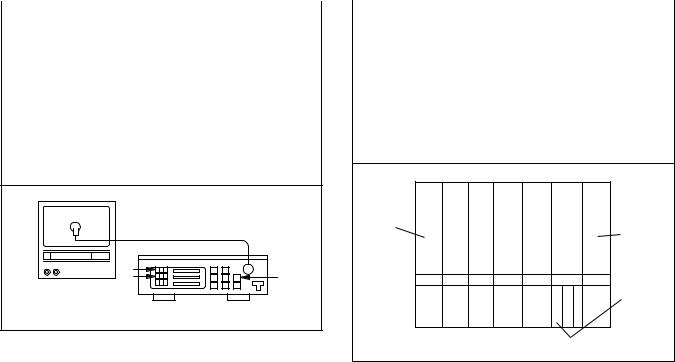
Test Equipment Required
1.PAL Pattern Generator (Color Bar, Monoscope, Black Raster, White Raster, Sympte)
2.SECAM Pattern Generator (Gray Scale)
3.AC Milli Voltmeter (RMS)
4.Alignment Tape (9965 000 14514), Blank Tape (E180)
5.DC Voltmeter
6.Oscilloscope: Dual-trace with 10:1 probe,
V-Range: 0.001~50V/Div,
F-Range: DC~AC-60MHz
7.Frequency Counter
8.Plastic Tip Driver
9.RF input (at each broadcasting system)
Receiving Channel : VHF Low Input level : 80dB V
10.Ext.input
FRONT VIDEO-IN JACK or REAR SCART JACK
How to Set up the Service mode:
NOTE:
How to set up the option code
1.Enter the Service mode.
2.Press the [STATUS/EXIT] button on the remote control unit. The option code appears on the display.
3.If needed, input the option code as shown below using number buttons on the remote control unit.
Model |
Option Code |
|
|
14PV135/01 |
0130 |
|
|
14PV135/07 |
0128 |
|
|
14PV135/58 |
0131 |
|
|
14PV235/01 |
0178 |
|
|
14PV235/07 |
0176 |
|
|
14PV235/58 |
0179 |
|
|
14PV385/01 |
2994 |
|
|
14PV385/07 |
2992 |
|
|
14PV385/39 |
2961 |
|
|
4.To reset the software, press [PAUSE] and [5] buttons on the remote control unit.
The option code is changed.
After replacing the IC202 (Memory) or Main CBA, the set value in IC202 (Memory) will be lost. So it is necessary to set up or adjust in the Service mode after its replacement.
Service Mode:
1.Turn the power on. (Use main power on the TV unit.)
2.Press [STANDBY/ON], [2], [7], [1], and [MUTE] buttons on the remote control unit in that order within 5 seconds.
-To cancel the service mode, press [STANDBY/ON] button on the remote control.
1-6-10 |
T6450EA |
1. DC 105V (+B) Adjustment
Purpose: To obtain correct operation.
Symptom of Misadjustment: The picture is dark and unit does not operate correctly.
Test point |
Adj. Point |
Mode |
Input |
|
|
|
|
|
|
|
|
|
|
|
TP503 |
|
|
Color |
|
(+B), |
VR601 |
RF |
||
TP504 |
(or Ext.) |
Bar |
||
|
||||
(GND) |
|
|
|
|
|
|
|
|
|
Tape |
M. EQ. |
Spec. |
||
|
|
|
|
|
|
|
|
|
|
--- |
DC Voltmeter, |
+105±0.5V DC |
||
Plastic Tip Driver |
||||
|
|
|
||
|
|
|
|
|
Note: TP503(+B), TP504(GND), VR601 --- H.V./Power |
||||
Supply CBA |
|
|
|
|
1.Connect the unit to AC Power Outlet. (exact AC230V)
2.Input a color bar signal from RF (or Ext.) input and leave it for at least 20 minutes.
3.Connect DC Volt Meter to TP503(+B) and TP504(GND).
4.Adjust VR601 so that the voltage of TP503(+B) becomes +105±0.5V DC.
2. H Adjustment
Purpose: To get correct horizontal position and size of screen image.
Symptom of Misadjustment: Horizontal position and size of screen image may not be properly displayed.
Test point |
Adj. Point |
Mode |
|
Input |
|
|
|
|
|
|
|
|
|
|
R590 |
P+/P- |
Ext. |
|
--- |
buttons |
|
|||
|
|
|
|
|
|
|
|
|
|
Tape |
M. EQ. |
|
Spec. |
|
|
|
|
||
|
|
|
||
--- |
Frequency Counter |
15.625kHz±75Hz |
||
|
|
|
|
|
Note: R590 --- H.V./Power Supply CBA
1.Connect Frequency Counter to R590.
2.Set the unit to the Ext. mode and no input is necessary. Enter the Service mode.
(See page 1-6-10.)
3.Operate the unit for at least 20 minutes.
4.Press [2] button on the remote control unit and select H-Adj Mode.
5.Press [P+/P-] buttons on the remote control unit so that the display will change [0] to [7.]
At this moment, choose display [0] to [7] when the
Frequency counter display is closest to 15.625kHz±75Hz.
6.Turn the power off and on again.
1-6-11 |
T6450EA |

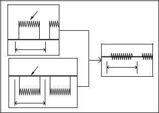
3. C-Trap Adjustment
Purpose: To get minimum leakage of the color signal carrier.
Symptom of Misadjustment: If C-Trap Adjustment is incorrect, stripes will appear on the screen.
Test point |
|
|
|
Adj. Point |
|
Mode |
|
|
Input |
||||||||
|
|
|
|
|
|
|
|
|
|
|
|
|
|
|
|
|
|
|
|
|
|
|
|
|
|
|
|
|
|
|
|
|
|
|
|
J349F3 |
|
|
|
P+/P- |
|
RF |
Color Bar |
||||||||||
(B-OUT) |
|
|
|
buttons |
(or Ext.) |
||||||||||||
|
|
|
|
|
|
|
|
|
|
|
|
|
|
|
|
|
|
Tape |
|
|
|
M. EQ. |
|
|
Spec. |
||||||||||
|
|
|
|
|
|
|
|
|
|
|
|
|
|
|
|
|
|
|
|
|
|
|
|
|
|
|
|
|
|
|
|
|
|
|
|
--- |
|
|
|
|
Oscilloscope, |
|
200mVp-p Max. |
||||||||||
|
|
|
Pattern Generator |
|
|||||||||||||
|
|
|
|
|
|
|
|
|
|
|
|||||||
|
|
|
|
|
|
|
|
|
|
|
|
|
|
|
|
|
|
|
|
|
|
|
|
|
|
Figure |
|
|
|
|
|
|
|
||
|
|
|
|
|
|
|
|
|
|
|
|
|
|
|
|
|
|
minimum |
|
|
|
|
|
|
|
|
|
|
|
|
|
Fig. 1 |
|||
|
|
|
|
|
|
|
|
|
|
|
|
|
|||||
|
|
|
|
|
|
|
|
|
|
|
|
|
|||||
|
|
|
|
|
|
|
|
|
|
|
|
|
|
|
|
|
|
|
|
|
|
|
|
|
|
|
|
|
|
|
|
|
|
|
|
|
|
|
|
|
|
|
|
|
|
|
|
|
|
|
|
|
|
|
|
|
|
|
|
|
|
|
|
|
|
|
|
|
|
|
|
|
|
|
|
|
|
|
|
|
|
|
|
|
|
|
|
|
|
Note: J349F3 (B-Out)--- Main CBA |
|
|
|
||||||||||||||
1.Connect Oscilloscope to J349F3.
2.Input a color bar signal from RF (or Ext.) input. Enter the Service mode. (See page 1-6-10.)
3.Press [0] button on the remote control unit and select C-TRAP Mode.
4.Press [P+/P-] buttons on the remote control unit so that the carrier leakage B-Out (4.43MHz) value becomes minimum on the oscilloscope.
5.Turn the power off and on again.
4. How to measure the standard V-ENV value of Digital Studio Picture Control
Purpose: To set the recording condition appropriate for the recording tape.
Symptom of Misadjustment: Recording or playing back picture quality may fall. The picture will be tinted.
1.Insert a new tape (type: E180) for the DSPC alignment into the TV/VCR.
2.Input the black raster signal from the video input jack (VIDEO-IN).
3.Enter the Service Mode. (See page 1-6-10.)
4.To enter the DSPC mode, press [1] button on the remote control unit. Recording starts automatically and “DSPC” appears on the display.
TVCR
DSPC
|
|
|
|
Fig. 2 |
|
|
|
|
|
VIDEO INPUT JACK (Ext. input) |
||||
5.Recording continues for 10 seconds in SP mode. Note: Since the reference value of LP V-ENV is computed from the reference value of SP V-ENV, there is no need to survey it.
6.The tape is rewinded to the recording start point.
7.The unit enters the play mode automatically and the V-ENV levels of each the reference value of SP mode and the computing value of LP mode are memorized into the EEPROM.
8."OK" or "NG" appears on upper left corner of the screen with blueback.
In case of "OK": "OK" (green) is indicated without ejecting tape.
In case of "NG": "NG" (red) is indicated with eject-
ing tape.
l
|
|
TVCR |
|
|
|
TVCR |
||||
|
|
|
|
|
|
|
|
|
|
|
|
OK |
|
|
|
NG |
|
||||
|
|
|
|
|
|
|
|
|
|
|
|
|
|
|
|
|
|
|
|
|
|
|
|
|
|
|
|
|
|
|
|
|
|
|
|
|
|
|
|
|
|
|
|
Normal |
Abnormal |
Fig. 3
1-6-12 |
T6450EA |
5. SECAM Black Level Adjustment
Purpose: To set Black Level of the SECAM signal R- Y/B-Y to Ref. level.
Symptom of Misadjustment: If Black Level of the SECAM signal R-Y/B-Y is incorrect, the picture is bluish or reddish in grayscale compared with PAL signal.
Test |
Adj. Point |
Mode |
Input |
|
point |
||||
|
|
|
||
|
|
|
|
|
|
|
|
|
|
|
P+/P- |
|
SECAM |
|
J361G4 |
Ext. |
Gray |
||
buttons |
||||
|
|
Scale |
||
|
|
|
||
|
|
|
|
|
Tape |
M. EQ. |
Spec. |
||
|
|
|
|
|
|
|
|
|
|
|
Pattern Generator, |
|
|
|
--- |
Analog Oscilloscope (unus- |
|
--- |
|
|
able Digital Oscilloscope) |
|
|
|
|
|
|
|
|
1.Degauss the CRT and allow CRT to operate for 20 minutes before starting the alignment.
2.Input the SECAM Gray Scale signal from Ext. input.
3.Enter the Service Mode. (See page 1-6-10.)
4.To enter the C/D/S mode, press [  -] on the remote control unit.
5.To select SBR (SECAM Black Level R-Y), press [6] button on the remote control unit.
6.Press [P+/P-] buttons to adjust Y signal to the black ref. level.
7.To select SBB (SECAM Black Level B-Y), press [7] button on the remote control unit.
8.Press [P+/P-] buttons to adjust Y signal to the black ref. level.
Y Signal |
|
1H |
|
Black REF. Level |
1H |
|
5mV/Div (10:1 Prove) |
1H |
Fig. 4 |
|
6. V. Size Adjustment
Purpose: To obtain correct vertical height of screen image.
Symptom of Misadjustment: If V. Size is incorrect, vertical height of image on the screen may not be properly displayed.
Test point |
Adj. Point |
Mode |
Input |
|
|
|
|
|
|
|
|
Screen |
P+/P- |
RF |
Monoscope |
buttons |
(or Ext.) |
||
|
|
|
|
Tape |
M. EQ. |
Spec. |
|
|
|
|
|
|
|
|
|
--- |
Pattern Generator |
90±5% |
|
|
|
|
|
1.Enter the Service mode. (See page 1-6-10.)
Press [9] button on the remote control unit and select V-S Mode. (Press [9] button then display will change to V-P and V-S).
2.Input monoscope pattern and leave it for at least 20 minutes.
3.Press [P+/P-] buttons on the remote control unit so that the monoscope pattern is 90±5% of display size and the circle is round.
7. V. Shift Adjustment
Purpose: To obtain correct vertical position of screen image.
Symptom of Misadjustment: If V. position is incorrect, vertical position of image on the screen may not be properly displayed.
Test point |
Adj. Point |
Mode |
Input |
|
|
|
|
|
|
|
|
Screen |
P+/P- |
RF |
Monoscope |
buttons |
(or Ext.) |
||
|
|
|
|
Tape |
M. EQ. |
Spec. |
|
|
|
|
|
|
|
|
|
--- |
Pattern Generator |
90±5% |
|
|
|
|
|
1.Enter the Service mode. (See page 1-6-10.)
Press [9] button on the remote control unit and select V-P Mode. (Press [9] button then display will change to V-P and V-S).
2.Input monoscope pattern and leave it for at least 20 minutes.
3.Press [P+/P-] buttons on the remote control unit so that the top and bottom of the monoscope pattern are equal to each other.
1-6-13 |
T6450EA |
8. H. Shift Adjustment
Purpose: To obtain correct horizontal position and size of screen image.
Symptom of Misadjustment: Horizontal position and size of screen image may not be properly displayed.
Test point |
Adj. Point |
Mode |
Input |
|
|
|
|
|
|
|
|
Screen |
P+/P- |
RF |
Monoscope |
buttons |
(or Ext.) |
||
|
|
|
|
Tape |
M. EQ. |
Spec. |
|
|
|
|
|
|
|
|
|
--- |
Pattern Generator |
90±5% |
|
|
|
|
|
1.Enter the Service mode. (See page 1-6-10.)
Press [8] button on the remote control unit and select H-P Mode.
2.Input monoscope pattern and leave it for at least 20 minutes.
3.Press [P+/P-] buttons on the remote control unit so that the left and right side of the monoscope pattern are equal to each other.
4.Turn the power off and on again.
9. Cut-off Adjustment
Purpose: To adjust the beam current of R, G, B, and screen voltage.
Symptom of Misadjustment: White color may be reddish, greenish or bluish.
Test point |
Adj. Point |
Mode |
Input |
|
|
|
|
|
|
|
|
|
|
|
Screen |
Screen-Control, |
RF |
Black |
|
P+/P-buttons |
(or Ext.) |
Raster |
||
|
||||
|
|
|
|
|
Tape |
M. EQ. |
Spec. |
||
|
|
|
||
|
|
|
||
--- |
Pattern Generator |
See Reference |
||
Notes below |
||||
|
|
|||
|
|
|
|
|
Notes:
Screen Control (FBT) --- H.V./Power Supply CBA
FBT= Fly Back Transformer
Use the Remote Control Unit
1.Degauss the CRT and allow CRT to operate for 20 minutes before starting the alignment.
2.Set the screen control to minimum position. Input the Black raster signal from RF (or Ext.) input.
3.Enter the Service Mode. (See page 1-6-10.) Dimmed horizontal line appears on the CRT.
4.To enter the C/D/S mode, press the [  -] button on the remote control unit.
5.To enter the CUT OFF (R) mode, press [1] button on the remote control unit.
6.Turn the screen control up until dimmed horizontal line appears.
7.Press the [P+/P-] buttons until the horizontal line becomes white.
8.To enter the CUT OFF (G) mode, press [2] button on the remote control unit.
9.Press the [P+/P-] buttons until the horizontal line becomes white.
10.To enter the CUT OFF (B) mode, press [3] button on the remote control unit.
11.Press the [P+/P-] buttons until the horizontal line becomes white.
12.Turn the screen control so that the horizontal line adjusted white looks lightly.
13.Turn the power off and on again.
1-6-14 |
T6450EA |
10. White Balance Adjustment
Purpose: To mix red, green and blue beams correctly for pure white.
Symptom of Misadjustment: White becomes bluish or reddish.
Test point |
Adj. Point |
Mode |
Input |
|
|
|
|
|
|
|
|
|
|
|
|
Screen-Control, |
RF |
White |
|
Screen |
Raster |
|||
P+/P-buttons |
(or Ext.) |
|||
|
(APL 100%) |
|||
|
|
|
|
|
Tape |
M. EQ. |
Spec. |
||
|
|
|
|
|
|
|
|
|
|
--- |
Pattern Generator, |
See below |
||
Color analyzer |
||||
|
|
|
||
|
|
|
|
|
|
Figure |
|
|
|
Color Ajalyzer |
Fig. 5 |
Note: Use remote control unit
1.Operate the unit more than 20 minutes.
2.Face the unit to east. Degauss the CRT using Degaussing Coil.
3.Input the White Raster (APL 100%).
4.Set the color analyzer to the CHROMA mode and after zero point calibration, bring the optical receptor to the center on the tube surface (CRT).
5.Enter the Service mode. Press [  -] button on the remote control.
6.Press [4] button on the remote control unit for Red adjustment. Press [5] button on the remote control unit for Blue adjustment.
7.In each color mode, Press [P+/P-] buttons to adjust the values of color.
8.Adjusting Red and Blue color so that the temperature becomes 8500K (x : 290 / y : 300) ±3%.
9.At this time, Re-check that Horizontal line is white. If not, Re-adjust Cut-off Adjustment until the Horizontal Line becomes pure white.
10.Turn off and on again to return to normal mode. Receive APL 100% white signal and Check Chroma temperatures become 8500K (x : 290 / y : 300) ±3%.
Note: Confirm that Cut Off Adj. is correct after this adjustment, and attempt Cut Off Adj. if needed.
11. Sub-Brightness Adjustment
Purpose: To get proper brightness.
Symptom of Misadjustment: If Sub-Brightness is incorrect, proper brightness cannot be obtained by adjusting the Brightness Control.
|
Test point |
Adj. Point |
Mode |
Input |
|
|
|
|
|
|
|
|
|
|
|
|
|
|
Screen |
P+/P- |
RF |
SYMPTE |
|
|
buttons |
(or Ext.) |
|||
|
|
|
|
|
|
|
Tape |
M. EQ. |
Spec. |
||
|
|
|
|
|
|
|
|
|
|
|
|
--- |
Pattern |
See below |
|||
Generator |
|||||
|
|
|
|
||
|
|
|
|
|
|
|
|
Figure |
|
|
|
White |
|
Black |
|
|
|
|
|
This bar |
|
A B C |
(A) just |
|
visible |
|
|
|
|
|
|
Fig. 6 |
Note: Bar (A) in Fig. 7 --- 0 IRE
1.Enter the Service Mode. (See page 1-6-10.)
Then input SYMPTE signal from RF (or Ext.) input and leave it for at least 20 minutes.
2.Press MENU button. (Each time MENU button is pressed, display will change BRT, CNT, COL, TNT, and SHP in that order.) Select BRT and press [P+/ P-] buttons so that the bar (A) in Fig. 6 is just visible.
3.Turn the power off and on again.
1-6-15 |
T6450EA |
12. Setting for CONTRAST, COLOR, TINT and SHARP Data Values
General
1.Enter the Service mode. (See page 1-6-10)
2.Press MENU button. (Each time MENU button is pressed, display will change BRT, CNT, COL, TNT, and SHP in that order.)
CONTRAST (CNT)
1.Press "MENU" button on the remote control unit. Then select CNT display.
2.Press [P+/P-] buttons on the remote control unit so that the value of "CONTRAST" (CNT) becomes 83.
COLOR (COL)
1.Press "MENU" button on the remote control unit. Then select "COLOR" (COL) display.
2.Press [P+/P-] buttons on the remote control unit so that the value of "COLOR" (COL) becomes 65.
TINT (TNT)
1.Press "MENU" button on the remote control unit. Then select "TINT" (TNT) display.
2.Press [P+/P-] buttons on the remote control unit so that the value of "TINT" (TNT) becomes 68.
SHARP (SHP)
1.Press "MENU" button on the remote control unit. Then select "SHARP" (SHP) display.
2.Press [P+/P-] buttons on the remote control unit and select "1."
13. Focus Adjustment
Purpose: Set the optimum Focus.
Symptom of Misadjustment: If Focus Adjustment is incorrect, blurred images are shown on the display.
Test point |
Adj. Point |
Mode |
Input |
|
|
|
|
|
|
|
|
Screen |
Focus Control |
RF |
Monoscope |
(or Ext.) |
|||
|
|
|
|
Tape |
M. EQ. |
Spec. |
|
|
|
|
|
|
|
|
|
--- |
Pattern Generator |
See below. |
|
|
|
|
|
Note: Focus VR (FBT) --- H.V./Power Supply CBA
FBT= Fly Back Transformer
1.Operate the unit more than 30 minutes.
2.Face the unit to the East and degauss the CRT using a Degaussing Coil.
3.Input the monoscope pattern.
4.Adjust the Focus Control on the FBT to obtain clear picture.
1-6-16 |
T6450EA |

14. Head Switching Position Adjustment
Purpose: Determine the Head Switching Position during Playback.
Symptom of Misadjustment: May cause Head Switching Noise or Vertical Jitter in the picture.
Note: Unit reads Head Switching Position automatically and displays it on the screen (Upper Left Corner).
Manual Adjustment
1.Enter the Service Mode. (See page 1-6-10.)
2.Playback the test tape (9965 000 14514).
3.Press the number [5] button on the remote control unit.
4.The Head Switching position will display on the
screen; if adjustment is necessary follow step 4. 7.0H (448 s) is preferable.
5.Press [P+/P-] buttons on the remote control unit if necessary. The value will be changed in 0.5H steps up or down. Adjustable range is up to 9.5H. If the value is beyond adjustable range, the display will change as:
Lower out of range: 0.0H Upper out of range: -.-H
6.Turn the power off and on again.
Auto Adjustment
1.Load the test tape (9965 000 14514) that have been recorded the Head Switching Position Value.
2.Enter the service mode.
3.Press [3] button on the remote control unit in the tape stop mode. The unit playback and adjust the Head Switching Position automatically.
4.The adjusting report appears on upper left corner of the screen with blueback.
In case of adjusting correctly: the Head Switching Position Value recorded in the test tape (9965 000 14514) is indicated with green.
In case of adjusting incorrectly: "NG" (red) is indi-
cated with ejecting tape.
l
|
|
TVCR |
|
|
|
TVCR |
||||
|
|
|
|
|
|
|
|
|
|
|
|
7.0H |
|
|
|
NG |
|
||||
|
|
|
|
|
|
|
|
|
|
|
|
|
|
|
|
|
|
|
|
|
|
|
|
|
|
|
|
|
|
|
|
|
|
|
|
|
|
|
|
|
|
|
|
Correct |
Incorrect |
Fig. 7
1-6-17 |
T6450EA |
Adjustment Points and Test Points
H.V./Power Supply CBA Top View
Focus-control (Upper side) |
Screen-control (Lower side) |
R590
(H Adjustment)
TP503
+B
VR601 |
TP504 |
|
+B ADJ |
||
GND |
||
|
Main CBA Top View
|
TP007 |
|
|
TP002 |
N-A-PB |
J361G4 |
|
RF-SW |
|
(SECAM |
|
TP001 |
|
Black Level |
|
|
Adjustment) |
||
CTL |
|
|
|
TP008 |
|
|
|
C-PB |
TP003 |
J349F3 |
|
|
B-OUT |
||
IC202 |
V-OUT |
||
|
TEST POINT INFORMATION
 : Indicates a test point with a jumper wire across a hole in the PCB.
TEST POINTS NOT USED IN ELECTRICAL ADJUSTMENTS
Test Point |
Used in: |
Page No. |
|
|
|
TP001 |
Mechanical Alignment Procedures |
2-3-3 |
|
|
|
TP002 |
Mechanical Alignment Procedures |
2-3-3, 2-3-4 |
TP008 |
Mechanical Alignment Procedures |
2-3-3, 2-3-4 |
|
|
|
TP503 |
Electrical Adjustment Instructions |
1-6-10 |
|
|
|
TP504 |
Electrical Adjustment Instructions |
1-6-10 |
|
|
|
1-6-18 |
T6450EA |

(DECK ASSEMBLY)
AC HEAD ASSEMBLY
CONTROL
HEAD
7-7-1
CYLINDER ASSEMBLY
PG
SENSOR
DRUM M
MOTOR
LOADING
MOTOR
T6450BLS
Comparison Chart of Models & Marks
|
NOTE FO R WI RE CONNECTORS: |
TEST POINT INFORMATION |
Model |
Mark |
Model |
Mark |
|
1. PREFIX SYMBOL "CN" MEANS CONNECTOR. |
|
|
|
|
|
|
:INDICATES A TEST POINT WITH A JUMPER WIRE ACROSS A HOLE IN THE PCB. |
14PV135/07 |
E |
14PV385/01 |
J |
|
" " = SMD |
(CAN DISCONNECT AND RECONNECT.) |
|||||
2. PREFIX SYMBOL "CL" MEANS WIRE-SOLDER |
:USED TO INDICATE A TEST POINT WITH A COMPONENT LEAD ON FOIL SIDE. |
14PV235/07 |
F |
14PV135/58 |
K |
|
|
:USED TO INDICATE A TEST POINT WITH NO TEST PIN. |
|||||
|
HOLES OF THE PCB. |
|
|
|
|
|
|
(WIRE IS SOLDERED DIRECTLY.) |
:USED TO INDICATE A TEST POINT WITH A TEST PIN. |
14PV385/07 |
G |
14PV235/58 |
L |
|
|
|
|
|
|
|
|
|
|
|
|
|
|
14PV135/01 |
H |
14PV385/39 |
M |
|
|
MAIN CBA |
|
|
|
|
|
|
IC201 |
|
|
|
|
|
14PV235/01 |
I |
|
|
|
|
|
|
|
|
|
|
|
|
|
|
|
|
|
|
|
|
|
|
|
|
|
|
|
AL+5V |
|
|
(SERVO/SYSTEM CONTROL) |
|
|
|
|
|
|
|
|||
|
|
|
|
|
|
|
|
|
|
|
|
SW201 |
SW205 |
|
|
|
|
|
|
|
|
|
|
|
|
|
|
|
KEY-1 |
7 |
KEY SWITCH |
|
|
|
|
||
|
|
|
|
D201 |
|
RS201 |
|
|
|
|
SW206 |
SW210 |
|
|
|
|
||
|
|
|
|
S-LED |
|
|
|
|
|
|
|
|
|
|
|
|
||
|
|
|
|
|
REMOTE |
14 REMOTEG,J,M |
KEY-2 |
8 |
KEY SWITCH |
|
|
|
|
|||||
|
|
|
|
|
|
SENSOR |
|
|
|
|
|
|
|
|
|
|||
|
|
|
|
|
|
WF3 |
|
C-POWER-SW 66 |
|
|
C-POWER-SW |
|
|
|
||||
|
|
|
|
|
|
TP001 |
|
|
|
|
|
TO POWER |
|
|||||
|
|
|
|
|
|
|
|
|
|
|
|
|
|
|
|
|
||
|
CL402 |
|
|
|
|
CTL |
|
97 CTL AMP-OUT |
|
|
|
|
|
|
|
|
||
|
|
|
|
|
|
|
|
|
|
|
P-ON-H |
|
SUPPLY BLOCK |
|||||
CTL(+) |
2 |
|
|
|
|
|
|
95 CTL(+) |
|
P-ON-H |
67 |
|
|
|
|
|
|
|
|
|
|
|
|
|
|
|
|
|
P-DOWN-L |
|
|
|
|||||
CTL(-) |
1 |
|
|
|
|
|
|
94 CTL(-) |
|
P-DOWN-L |
85 |
|
|
|
|
|
|
|
|
|
|
|
|
|
|
|
|
|
|
|
|
|
|||||
|
|
|
|
SW212 |
|
|
|
|
|
|
D202 |
REC |
|
|
|
|
|
|
|
|
|
|
|
AL+5V |
|
|
|
|
|
|
|
|
|
|
|
||
|
|
|
|
LD-SW |
|
|
|
REC-LED 23 |
|
|
AL+5V |
|
|
|
||||
|
|
|
|
|
|
|
|
|
|
|
|
|
||||||
|
|
|
|
|
|
|
|
9 LD-SW |
|
REC-LED |
24 |
D204 |
STANDBY |
|
|
|
|
|
|
|
|
|
|
|
|
|
|
|
|
|
|
|
|
||||
|
|
|
|
|
|
|
|
|
|
|
|
|
|
|
|
|
|
|
|
|
|
|
|
|
|
|
|
|
|
|
|
|
|
IC202 (MEMORY) |
|
|
|
|
|
|
|
|
|
|
|
10 ST-SENS. |
|
SCL 71 |
|
|
6 |
SCL |
|
|
|
|
|
|
|
|
|
|
|
|
4 END-SENS. |
|
SDA 72 |
|
|
5 |
SDA |
|
|
|
|
|
|
|
|
|
G,J,M |
|
80 T-REEL |
|
I2C-OPEN 45 |
|
|
7 |
CS |
|
|
|
||
|
Q202 |
|
Q201 |
|
|
PI201 |
|
79 S-REEL |
|
|
|
|
|
|
SCL |
|
|
|
|
ST-SENS. |
|
END-SENS. |
Q205 |
|
|
|
|
|
|
|
|
|
|
|
|
||
|
|
|
|
|
|
|
|
|
|
|
SDA |
|
TO |
|
||||
|
|
|
|
|
|
|
|
|
|
|
|
|
|
|||||
|
|
|
|
|
|
S-REEL |
|
|
|
|
|
|
|
|
|
|||
|
SENSOR CBA |
SENSOR CBA |
T-REEL |
|
|
|
|
|
|
|
I2C-OPEN |
|
TV BLOCK |
|
||||
|
|
|
|
|
|
|
|
|
|
|
|
|
|
|
|
|||
|
(ST-SENSOR) |
(END-SENSOR) |
|
|
|
|
|
G,J,M |
|
|
|
|
|
|
|
|
||
|
|
|
|
|
|
|
|
|
|
|
|
|
|
|
|
|
||
|
|
|
|
|
|
|
|
|
1ST-SND-H 21 |
|
|
|
1ST-SND-H |
|
|
|
||
|
|
|
|
|
|
|
|
|
|
|
|
|
|
|
|
|||
|
|
|
|
|
|
Q204 |
|
|
|
|
|
|
|
|
SP-MUTE |
|
|
|
|
|
|
|
TIMER+5V |
RESET |
|
34 RESET |
|
SP-MUTE 44 |
|
|
|
|
|
|
|||
|
|
|
|
|
|
|
|
|
A-MUTE-H |
|
|
|||||||
|
|
|
|
|
|
|
|
|
|
A-MUTE-H 20 |
|
|
|
|
|
|||
|
|
|
|
|
|
|
|
|
|
|
|
|
EXT-L |
|
TO |
|
||
|
CAPSTAN MOTOR |
|
|
|
|
|
|
EXT-L 42 |
|
|
|
|
|
|||||
|
|
|
|
|
|
|
SCART-H 48 |
|
|
|
SCART-H |
|
AUDIO BLOCK |
|
||||
|
|
|
|
|
|
|
|
|
|
|
|
SCART-MUTE |
|
|
|
|||
|
|
|
|
CN201 |
|
|
|
SCART-MUTE 29 |
|
|
|
|
|
|||||
|
|
|
|
|
|
|
|
|
|
SCL |
|
|
|
|||||
|
|
|
CM+12V/+20.5V |
1 |
CM+12V/+20.5V |
|
|
|
|
|
|
|
|
|
|
|||
|
|
|
P-ON+5V(3) |
2 |
P-ON+5V(3) |
|
|
|
|
|
|
|
|
SDA |
|
|
|
|
|
CAPSTAN |
M |
C-FG |
3 |
|
|
|
87 C-FG |
|
|
|
|
|
|
|
|
|
|
|
C-F/R |
4 |
|
|
|
78 C-F/R |
REC-SAFETY |
31 |
SW211 |
|
SCL |
|
|
|
||||
|
MOTOR |
|
|
|
|
|
|
|
||||||||||
|
|
|
|
76 C-CONT |
|
|
|
REC |
|
|
|
|
|
|||||
|
|
|
C-CONT |
5 |
|
|
|
|
|
|
|
|
SDA |
|
|
|
||
|
|
|
FG-GND |
6 |
|
|
|
|
|
G,J |
|
SAFETY |
|
|
|
|
|
|
|
|
|
|
|
|
81 LD-CONT |
|
|
|
|
|
|
|
|
|
|||
|
|
|
LD-CONT |
7 |
|
|
|
|
|
|
|
|
|
DAV-L |
|
|
|
|
|
|
|
D-CONT |
8 |
|
|
|
77 D-CONT |
|
DAV-L 83 |
|
|
|
|
|
|
||
|
|
|
|
|
|
|
|
|
|
|
|
|
|
|||||
|
|
|
D-PFG |
9 |
|
|
|
90 D-PFG |
|
D-REC-H |
|
|
|
|
D-REC-H |
|
|
|
|
|
|
M-GND |
10 |
|
|
|
|
|
47 |
|
|
|
|
|
|
|
|
|
|
|
|
|
|
|
|
|
|
|
|
C-SYNC |
|
|
||||
|
|
|
AL+12V(1) |
11 |
AL+12V(1) |
|
|
|
C-SYNC |
74 |
|
|
|
|
|
|||
|
|
|
+33V |
|
|
|
|
|
DV-SYNC |
TO |
|
|||||||
|
|
|
VG |
12 |
|
|
|
|
DV-SYNC |
13 |
|
|
|
|
||||
M |
|
|
|
|
|
|
|
|
|
|
V-ENV |
VIDEO BLOCK |
|
|||||
|
|
|
|
|
|
|
|
|
V-ENV |
6 |
|
|
|
|
||||
|
|
|
|
|
|
|
|
|
|
|
|
C-ROTA |
|
|
||||
|
|
|
|
|
|
|
|
|
C-ROTA |
15 |
|
|
|
|
|
|||
|
|
|
|
|
|
|
|
|
|
|
|
|
RF-SW |
|
|
|||
|
|
|
|
|
|
|
|
|
M |
RF-SW 18 |
|
|
|
|
|
|||
|
|
|
|
|
|
|
|
|
|
|
|
|
|
|
|
|||
|
|
|
|
|
|
|
|
|
|
TRICK-H |
|
|
|
|
TRICK-H |
|
|
|
|
|
|
|
|
|
|
|
|
|
33 |
|
|
|
SECAM-H |
|
|
|
|
|
|
|
|
|
|
|
|
|
|
SECAM-H |
|
|
|
|
|
|
||
|
|
|
|
|
|
|
|
|
|
32 |
|
|
|
|
|
|
|
|
|
|
|
|
|
|
|
|
|
|
|
|
|
|
|
|
|
|
|
01,( 14PV235/ ), 58 07, 01, ( 14PV135/ [ DiagramBlock Control Servo/System |
BLOCK |
14PV385/ ), 58 07, |
DIAGRAMS |
] ) 39 07, 01, ( |
|

NOTE FOR WIRE CONNECTORS:
1.PREFIX SYMBOL "CN" MEANS CONNECTOR. (CAN DISCONNECT AND RECONNECT.)
" " = SMD |
2. PREFIX SYMBOL "CL" MEANS WIRE-SOLDER |
|
HOLES OF THE PCB. |
|
(WIRE IS SOLDERED DIRECTLY.) |
Comparison Chart of Models & Marks
TEST POINT INFORMATION |
|
|
Model |
Mark |
Model |
Mark |
:INDICATES A TEST POINT WITH A JUMPER WIRE ACROSS A HOLE IN THE PCB. |
|
|
||||
:USED TO INDICATE A TEST POINT WITH A COMPONENT LEAD ON FOIL SIDE. |
|
|
14PV135/07 |
E |
14PV385/01 |
J |
:USED TO INDICATE A TEST POINT WITH NO TEST PIN. |
|
|
14PV235/07 |
F |
14PV135/58 |
K |
:USED TO INDICATE A TEST POINT WITH A TEST PIN. |
|
|
|
|
|
|
|
|
14PV385/07 |
G |
14PV235/58 |
L |
|
|
|
|
||||
REC-VIDEO SIGNAL |
PB-VIDEO SIGNAL |
MODE: SP/REC |
14PV135/01 |
H |
14PV385/39 |
M |
14PV235/01 |
I |
|
|
|||
|
|
|
|
|
|
|
MAIN CBA |
|
TO |
|
DAV-L |
|
|
|
|
|
IC101 (VPS) |
|
|
|
|
|
|
|
|
|
|
|
|
|
|
|
|
|
|
|
||||
|
|
|
|
|
|
|
|
|
14 DAV-L |
|
|
|
|
||||
|
|
|
|
|
SERVO/SYSTEM |
SDA |
|
|
|
|
|
|
|
|
|||
|
|
|
|
|
CONTROL BLOCK |
|
|
|
|
6 |
SDA |
|
|
|
|
||
|
|
|
|
|
|
|
SCL |
|
|
|
|
|
|
|
|
||
|
|
|
|
|
|
|
|
|
|
|
7 |
SCL |
|
|
|
|
|
|
|
TO |
C-VIDEO |
|
|
|
|
|
|
|
|
|
|
|
|||
|
|
|
|
|
|
|
|
|
16 VPS-V |
|
|
|
|
||||
|
|
TV BLOCK |
|
|
|
|
|
|
|
|
|
|
|
|
|||
|
TU001 |
|
|
|
|
|
|
|
|
|
|
|
|
|
|
|
|
|
VIDEO OUT |
17 |
|
|
|
|
|
|
|
|
|
|
G,J |
|
|
|
|
|
|
|
|
|
|
|
|
|
|
|
|
|
|
|
|||
|
TU002 |
|
G,J,M |
|
IC401 |
|
|
|
|
|
|
|
|
|
|
|
|
|
|
|
|
|
|
|
|
|
|
|
|
|
|
|
|
||
|
|
|
|
|
|
|
|
|
|
|
|
|
|
|
|
|
|
|
VIDEO OUT |
17 |
|
(VIDEO/AUDIO SIGNAL PROCESS) |
65 |
43 |
46 |
68 69 |
78 |
79 |
|
|
|
|
|
|
|
|
|
|
|
|
|
|
|
|
|
|
|
|
|
|
|||
|
|
|
|
|
|
|
|
|
SERIAL |
|
|
|
|
|
|
|
(DECK ASSEMBLY) |
|
|
|
|
|
|
|
Y. DELAY |
|
|
|
|
|
|
|
|
|
|
|
JK701 |
|
|
|
|
|
DECORDER |
|
|
|
|
|
|
|
CYLINDER ASSEMBLY |
||
|
V-IN |
|
|
|
|
|
|
|
|
|
|
|
|
|
CL401 |
|
|
|
|
|
|
|
|
|
|
|
|
|
|
|
|
|
|
|
|
|
|
|
|
|
|
|
LUMINANCE |
R |
|
P |
SP |
96 |
V(R) |
1 |
VIDEO (R) |
||
|
|
|
|
|
|
|
|
|
|
95 |
V-COM |
2 |
HEAD |
||||
|
|
|
|
|
|
|
SIGNAL |
|
|
|
|
HEAD |
|||||
|
|
|
|
|
|
|
|
|
|
|
93 |
V(L) |
3 |
|
|||
|
|
|
|
WF4 |
|
|
PROCESS |
|
|
|
|
AMP |
VIDEO (L) |
||||
|
|
|
|
|
|
|
|
|
|
|
|
|
94 |
|
|
HEAD |
|
|
|
|
|
|
|
|
|
|
|
|
|
|
|
|
|
||
|
|
|
|
48 |
TUNER1 |
AGC |
|
|
|
|
|
|
|
|
|
|
|
|
|
JK703 |
|
BYPASS |
|
|
|
|
|
|
|
|
|
|
|
||
8-7-1 |
|
|
50 |
TUNER2 |
|
|
|
|
|
|
|
|
|
|
|
|
|
V-OUT |
19 |
|
SCART |
|
|
|
|
|
|
|
|
|
|
|
|
||
|
54 |
|
|
|
|
|
|
|
|
|
|
|
|
||||
|
V-IN |
20 |
|
52 |
LINE |
|
|
|
|
|
|
|
|
|
|
|
|
|
|
|
|
|
|
|
|
|
|
|
|
|
|
|
|
|
|
|
|
|
|
56 |
SCART |
CHARA. |
|
|
|
|
|
|
|
|
|
|
|
|
|
|
|
|
LINE |
INS. |
|
CCD 1H DELAY |
Y |
|
|
|
|
|
|
|
|
|
|
|
|
|
|
|
|
|
|
|
WF1 |
|
|
||||
|
|
|
|
|
PB/EE |
|
|
|
+ |
REC FM |
|
|
|
||||
|
|
|
Q703 |
BUFFER |
|
|
|
|
|
|
|
|
|||||
|
|
|
|
|
|
|
|
|
AGC |
|
|
TP002 |
|
|
|||
|
|
|
MUTE |
1/2 |
|
|
|
C |
|
|
|
|
|
||||
|
|
|
|
|
|
|
|
|
|
|
|
RF-SW |
|
|
|||
|
|
|
|
|
|
|
|
|
|
|
|
|
|
|
|
|
|
|
|
|
|
|
TUNER1 |
|
|
CHROMINANCE |
|
|
|
|
|
|
|
|
|
|
|
|
|
|
TUNER2 |
|
|
|
|
|
|
|
|
|
|
||
|
|
|
|
|
|
|
SIGNAL |
|
|
|
|
|
|
D-REC-H |
|
||
|
|
|
|
|
PB/EE |
|
|
|
|
|
|
D-REC-H |
80 |
|
|||
|
|
|
|
|
|
|
PROCESS |
|
|
|
RF-SW |
|
|||||
|
|
|
|
|
MUTE |
|
|
|
R |
P R |
|
P |
|
|
|
||
|
|
|
|
|
|
|
|
|
|
|
C-ROTA |
|
|||||
|
|
|
|
|
|
|
|
|
|
|
|
RF-SW/C-ROTA |
70 |
|
|||
|
|
|
|
|
|
|
|
|
|
|
|
|
|
||||
|
|
|
|
|
|
|
|
|
|
|
|
|
DV-SYNC |
|
|||
|
|
|
|
|
|
FBC |
Y/C |
|
|
|
|
|
D-V-SYNC |
62 |
|
||
|
|
|
|
WF5 |
|
|
|
|
|
|
|
|
|
||||
|
|
|
|
|
|
MIX |
|
|
|
|
|
|
|
|
|
TO SERVO/SYSTEM |
|
|
|
|
|
TP003 |
|
|
|
|
|
|
|
|
|
|
|
||
|
|
|
TU1-VIDEO |
|
|
|
|
|
|
|
|
|
|
|
|
CONTROL BLOCK |
|
|
|
|
|
|
|
|
|
|
|
|
|
|
|
|
|
||
TO |
|
V-OUT |
R |
P |
|
|
V-ENV |
84 |
V-ENV |
|
|
|
|
|
C-SYNC |
|
|||||
TV BLOCK |
VIDEO |
Q401 |
|
|
|
|
C-SYNC |
67 |
M |
|
|
BUFFER 61 |
|
|
|
|
|
||||
|
|
AGC |
VXO |
|
|
|
TRICK-H |
|
||
|
|
|
|
|
|
|
||||
|
|
|
|
|
|
SECAM-H |
|
|||
|
|
63 |
|
|
|
|
|
|
|
|
|
|
|
|
|
|
PB-H OUT |
|
|
|
|
|
|
|
|
|
|
|
|
IC471 (PAL/SECAM DECTECOTR) |
|
|
|
|
58 |
59 |
28 |
29 |
21 |
44 |
|
|
|
|
|
|
|
|
||||||
|
|
|
|
|
|
WF2 |
|
28 |
|
|
|
|
TP010 |
|
|
|
|
1 |
|
|
|
|
|
|
X401 |
|
TP008 |
|
|
|
||
|
|
GND |
|
|
|
29 |
|
|
||
|
|
|
4.43MHz |
C-PB |
|
PAL/SECAM |
|
|||
|
|
|
|
|
17 |
|
||||
|
|
|
|
|
|
|
|
|||
|
|
|
|
|
|
WF6 |
|
12 |
DETECTOR |
|
|
|
|
|
|
|
|
|
2 |
|
|
T6450BLV |
|
|
|
|
|
|
|
|
|
|
|
|
|
|
|
|
|
16 |
|
|
|
|
|
|
|
|
|
|
|
14 |
|
|
Diagram Block Video

|
NOTE FOR WIRE CONNECTORS: |
TEST POINT INFORMATION |
|
|
|
|
1. PREFIX SYMBOL "CN" MEANS CONNECTOR. |
:INDICATES A TEST POINT WITH A JUMPER WIRE ACROSS A HOLE IN THE PCB. |
|
|
|
" " = SMD |
(CAN DISCONNECT AND RECONNECT.) |
:USED TO INDICATE A TEST POINT WITH A COMPONENT LEAD ON FOIL SIDE. |
|
|
|
|
2. PREFIX SYMBOL "CL" MEANS WIRE-SOLDER |
:USED TO INDICATE A TEST POINT WITH NO TEST PIN. |
|
|
|
|
HOLES OF THE PCB. |
:USED TO INDICATE A TEST POINT WITH A TEST PIN. |
PB-AUDIO SIGNAL |
REC-AUDIO SIGNAL |
Mode : SP/REC |
|
(WIRE IS SOLDERED DIRECTLY.) |
|
|||
|
|
|
|
|
|
|
|
|
|
|
IC301 (VIDEO/AUDIO/CHROMA/DEFLECTION/IF) |
MAIN CBA |
|
|
|
|
|
||
|
|
|
|
|
|
IC151 (AMP) |
|
|
|
|
||||
TU001 |
|
|
|
|
WF7 |
|
|
|
|
|
|
|
||
|
|
|
|
|
|
|
|
|
|
|
|
|
||
|
|
|
|
|
TUNER1 |
|
|
|
|
|
|
|
|
|
AUDIO OUT 6 |
|
|
|
52 |
ATT |
|
|
OUTPUT |
|
|
|
|
||
|
|
|
|
|
|
LINE |
50 |
7 |
1 |
|
|
|
||
|
|
|
|
G,J,M |
53 |
AMP |
|
|
|
|||||
|
|
|
|
|
|
|
|
|
MUTE |
|
|
|
|
|
AUDIO OUT 21 |
|
|
|
|
|
|
|
|
|
|
|
|
||
|
|
|
|
AUDIO |
|
|
|
5 |
|
|
|
|
||
|
|
|
|
|
54 |
|
|
|
|
|
|
|
||
|
|
|
|
|
|
|
|
|
|
|
|
|
||
TU002 |
|
IC702 (SW) |
|
|
MUTE |
|
|
|
|
|
|
|
|
|
|
|
|
|
|
|
|
|
|
|
|
|
|||
|
|
TU1 |
|
|
|
|
|
|
|
|
CN804 |
|
||
|
14 |
|
13 |
|
|
|
|
|
|
|
|
|
||
|
TU2 |
|
|
|
|
|
|
|
|
SP |
|
1 |
||
TO SERVO |
|
|
12 |
|
|
|
|
|
|
|
|
|
||
|
|
|
|
|
|
|
|
|
|
SP-GND |
2 |
|||
/SYSTEM 1ST-SND-H |
SW CTL |
|
|
|
|
|
|
|
|
|
||||
CONTROL |
|
|
|
|
|
|
|
|
|
|
|
|
|
|
BLOCK |
|
|
|
|
|
|
|
|
|
|
|
|
|
|
JK702 |
|
11 |
|
|
|
|
|
|
|
|
|
|
|
|
|
|
|
|
|
|
|
|
|
|
|
|
|
|
|
A-IN |
|
|
IC701 (SW) |
|
|
|
|
|
|
|
SP-MUTE |
TO |
|
|
|
|
|
|
|
|
|
|
|
|
SERVO/SYSTEM |
|
|
||
|
|
|
|
|
|
|
|
|
|
|
|
|
|
|
|
|
|
SCART |
|
|
|
|
|
|
|
|
CONTROL BLOCK |
|
|
|
|
1 |
15 |
|
|
|
|
|
|
|
|
|
|
|
|
JK703 |
2 |
LINE |
|
|
|
|
|
|
|
|
|
|
|
|
|
|
|
|
|
|
|
|
|
|
|
|
|
|
A-IN |
2 |
5 |
SCART |
4 |
|
|
|
IC401 |
|
|
|
|
|
|
|
|
3 |
LINE |
|
|
|
|
|
|
|
|
|
||
A-OUT |
1 |
|
|
|
|
|
|
(AUDIO SIGNAL PROCESS) |
|
|
|
|
|
|
9-7-1 |
|
13 |
|
14 |
|
|
13 |
TUNER1 |
|
|
|
|
|
|
|
|
|
|
|
|
|
|
|
|
|
||||
|
|
12 |
|
|
|
|
|
|
|
|
|
|||
|
|
|
|
|
|
|
|
|
|
|
|
|||
|
|
|
|
|
|
|
|
|
|
|
|
|
||
|
|
|
|
|
|
15 TUNER2 |
|
|
|
|
|
|
||
|
|
|
|
|
|
|
|
|
|
|
|
|
||
|
|
|
SW CTL |
|
|
17 |
LINE |
|
|
|
|
|
ALC |
|
|
|
|
|
|
|
|
|
|
|
|
|
|
||
|
|
|
|
|
|
|
|
|
|
|
INV |
|
|
DET |
|
|
|
11 10 |
9 |
|
|
|
PB-ON |
WF9 |
|
|
|
|
|
|
|
|
|
|
|
|
|
R |
|
|
||||
|
|
|
|
|
|
|
|
|
|
|
|
|||
|
|
|
|
|
|
|
5 |
EQ |
|
|
|
ALC |
||
|
|
|
|
|
|
|
|
|
|
|
||||
|
|
|
|
|
|
|
8 |
9 |
|
ATT |
|
|||
|
|
|
|
|
|
|
6 |
AMP |
|
|
|
|||
|
|
|
|
|
|
|
|
|
|
P |
|
|
||
|
|
|
|
|
|
|
|
|
|
|
|
|
|
|
|
Q701 |
|
|
|
|
|
|
SP/LP-ON |
|
|
|
|
|
|
|
|
|
SCART-H |
TO SERVO |
|
|
|
|
|
|
|
|
|
|
|
|
|
|
+5V |
|
|
|
|
|
|
|
|
||
|
|
|
|
EXT-L |
/SYSTEM |
|
|
7 |
|
|
|
|
|
|
|
|
|
|
CONTROL |
|
|
|
|
|
|
|
|
|
|
|
|
|
SCART-MUTE |
|
|
|
|
|
|
|
|
|
||
|
|
|
BLOCK |
|
|
|
|
|
|
|
|
|
||
|
|
|
|
|
|
Q854 |
|
|
|
|
|
|
|
|
(DECK ASSEMBLY) |
|
|
|
|
|
|
|
|
|
|
|
|
|
|
|
|
|
|
|
CL402 |
|
|
|
|
|
|
|
|
|
|
AUDIO |
|
|
3 |
A-PB/REC |
Q855 |
1 |
AUTO |
3 |
100 |
|
REC |
|
|
|
HEAD |
|
|
4 |
A-COM |
|
|
|
||||||
|
|
|
2 |
BIAS |
|
AMP |
|
|
||||||
|
|
|
BIAS |
|
|
|
||||||||
|
|
|
|
|
|
|
|
|
||||||
|
AUDIO |
|
|
6 |
AE-H/FE-H |
|
|
|
|
|
|
|
|
|
|
|
|
OSC |
|
|
|
|
|
|
|
|
|||
|
ERASE |
|
|
5 |
FE-H |
|
|
|
|
|
|
|
|
|
|
|
|
Q856 |
|
|
|
|
|
|
|
|
|||
|
HEAD |
|
|
|
|
|
|
|
|
|
|
|
|
|
|
ACE HEAD ASSEMBLY |
|
|
|
Q853(PB=ON) |
|
|
|
|
|
|
SERIAL |
||
|
|
|
|
|
|
|
|
|
|
|
|
AUDIO HD-SW |
DECODER |
|
|
|
|
|
|
|
|
SWITCHING |
|
|
|
CONTROL |
|
|
|
|
|
|
|
|
|
|
|
|
|
16 |
68 69 |
|||
|
|
|
|
|
CL403 |
Q851 |
D-REC-OFF |
|
|
|
||||
|
FULL |
|
|
|
|
+5V |
|
|
|
|
|
|
||
|
|
|
1 |
FE-H |
|
|
|
|
|
|
|
|||
|
ERASE |
|
|
Q852(PB=ON) |
|
|
|
|
|
|
|
|
||
T6450BLA |
|
|
2 FE-H-GND |
|
|
|
|
|
|
|
|
|||
HEAD |
|
|
|
|
|
|
|
|
|
|
|
|||
|
|
|
|
|
|
|
|
|
|
|
|
|
||
|
FE HEAD |
|
|
|
|
|
|
|
|
|
|
|
|
|
Comparison Chart of Models & Marks
Model |
Mark |
Model |
Mark |
14PV135/07 |
E |
14PV385/01 |
J |
14PV235/07 |
F |
14PV135/58 |
K |
14PV385/07 |
G |
14PV235/58 |
L |
14PV135/01 |
H |
14PV385/39 |
M |
14PV235/01 |
I |
|
|
JK151
HEADPHONE JACK
CL801
SP151
SPEAKER
12
LINE
AMP  MUTE
MUTE 
 11
11
TP007
N-A-PB
WF8
REC-ON
71
A-MUTE-H |
TO |
|
SDA |
||
SERVO/SYSTEM |
||
SCL |
||
CONTROL BLOCK |
Diagram Block Audio

10-7-1
T6450BLT
|
|
|
|
|
|
|
|
|
|
|
|
|
|
|
|
|
|
|
|
|
TEST POINT INFORMATION |
|
NOTE FOR WIRE CONNECTORS: |
Comparison Chart of Models & Marks |
|||||||||
|
|
|
|
|
|
|
|
|
|
|
|
F,G,I,J,L,M |
|
|
|
|
|
|
|
:INDICATES A TEST POINT WITH A JUMPER WIRE ACROSS A HOLE IN THE PCB. |
1. PREFIX SYMBOL "CN" MEANS CONNECTOR. |
|
|
|
|
||||||||
|
|
|
|
|
|
|
|
|
|
|
|
" |
" = SMD |
|
:USED TO INDICATE A TEST POINT WITH A COMPONENT LEAD ON FOIL SIDE. |
|
(CAN DISCONNECT AND RECONNECT.) |
Model |
Mark |
Model |
Mark |
||||||||||||
|
|
|
|
|
|
|
|
|
|
|
|
|
|
|
|
:USED TO INDICATE A TEST POINT WITH NO TEST PIN. |
|
2. PREFIX SYMBOL "CL" MEANS WIRE-SOLDER |
|
|
|
|
|||||||||||
|
|
|
|
|
|
|
|
|
|
|
|
|
|
|
|
|
14PV135/07 |
E |
14PV385/01 |
J |
|||||||||||||
|
|
|
|
|
|
|
|
|
|
|
|
|
|
|
|
|
|
|
|
|
|
|
|||||||||||
|
|
|
|
|
|
|
|
|
|
|
|
|
|
|
|
|
|
|
|
|
|
:USED TO INDICATE A TEST POINT WITH A TEST PIN. |
|
HOLES OF THE PCB. |
|
|
|||||||
IC901 (TELETEXT DECODER) |
|
|
|
|
|
|
|
|
|
|
|
|
|
|
|
(WIRE IS SOLDERED DIRECTLY.) |
14PV235/07 |
F |
14PV135/58 |
K |
|||||||||||||
|
|
|
|
|
|
|
|
|
|
|
|
|
|
|
|
|
|
14PV385/07 |
G |
14PV235/58 |
L |
||||||||||||
|
|
|
|
|
|
|
|
|
|
|
|
|
|
|
|
|
|
|
|
|
|
|
|
|
|
|
|
|
|
||||
|
|
|
|
|
|
|
|
|
|
|
|
|
|
|
|
|
|
|
|
MAIN CBA |
|
|
|
|
|
|
|
|
|
14PV135/01 |
H |
14PV385/39 |
M |
|
|
|
|
|
ADC/ |
|
|
|
|
|
|
|
|
|
|
|
|
|
|
|
|
|
REC VIDEO SIGNAL |
PB VIDEO SIGNAL |
Mode : SP/REC |
||||||||
|
|
|
DATA SLICER |
|
23 |
|
|
|
|
CN901 |
|
CN751 |
|
|
|
|
14PV235/01 |
I |
|
|
|||||||||||||
|
|
|
|
|
|
|
|
|
|
|
|
|
|
|
|||||||||||||||||||
|
|
|
|
|
|
|
|
|
|
|
|
||||||||||||||||||||||
|
|
|
|
|
|
|
37 |
|
|
|
|
|
5 |
Y-SW-OUT |
5 |
|
|
|
|
|
|
|
|
|
|
|
|
|
|
|
|
|
|
|
|
|
|
|
DISPLAY |
|
|
|
|
|
|
|
|
|
|
|
|
|
|
|
|
|
|
|
|
|
|
|
|||||
|
|
|
|
|
TIMING |
|
36 |
|
|
|
|
|
1 |
V-SYNC |
1 |
|
|
|
|
|
|
|
|
|
|
|
|
|
|
|
|
|
|
|
|
|
|
|
|
|
|
|
|
|
|
|
2 |
H-SYNC |
2 |
|
|
|
|
|
|
|
|
IC301 (VIDEO/AUDIO/CHROMA/DEFLECTION/IF) |
|
|
|
|
|
|
|
||
|
|
|
|
|
|
|
50 |
|
|
|
|
|
4 |
SDA |
4 |
|
|
|
|
|
|
|
|
|
|
|
|
|
|
|
|||
|
|
|
|
|
I2C I/F |
|
49 |
|
|
|
|
|
3 |
SCL |
3 |
|
|
|
|
|
|
|
|
|
|
|
|
|
|
|
|
|
|
|
|
|
|
|
|
|
|
|
|
|
|
|
|
|
|
|
40 |
|
|
|
|
|
|
|
|
|
|
||||||
|
|
|
|
|
|
|
|
|
|
|
|
|
|
|
|
|
|
|
|
|
|
|
|
|
|
|
|
|
|
|
|||
|
|
|
|
|
|
|
|
|
|
|
|
CN902 |
|
CN752 |
|
|
|
|
|
|
|
|
|
|
|
|
|
|
|||||
|
|
|
|
|
TELETEXT |
|
35 |
|
|
|
|
|
2 |
OSD-BLK |
2 |
|
|
|
|
|
|
|
|
|
|
|
|
|
|
|
|
|
|
|
|
|
|
|
|
|
|
|
|
|
|
|
|
|
|
|
|
|
|
|
|
|
|
|
|
|
|
|
|||||
|
|
|
|
|
|
32 |
|
|
|
|
|
4 |
OSD-B |
4 |
|
|
|
|
|
|
|
|
|
|
|
|
|
|
|
|
|
|
|
|
|
|
|
|
|
|
|
|
|
|
|
|
|
|
|
|
|
|
|
|
|
|
|
|
|
|
|
|
|||||
|
|
|
|
|
DECODER |
|
33 |
|
|
|
|
|
6 |
OSD-G |
6 |
|
|
|
|
|
|
|
|
|
|
|
|
|
|
|
|
|
|
|
|
|
|
|
|
|
|
|
|
|
|
|
|
|
|
|
|
|
|
|
|
|
|
||||||||||
|
|
|
|
|
|
|
|
|
|
|
|
|
|
|
|
|
|
|
|
|
|
|
|
|
|
|
|
|
|
|
|
|
|
|
|
|
|
|
|
|
34 |
|
|
|
|
|
3 |
OSD-R |
3 |
|
|
|
|
|
|
|
|
|
|
|
|
|
|
|
|
|
|
|
|
|
|
|
|
|
X901 |
|
|
|
|
|
|
|
|
|
|
|
|
|
|
|
|
|
|
|
|||||||
|
|
|
|
|
|
|
|
|
|
|
|
|
|
|
|
|
|
|
|
|
|
|
|
|
|
|
|
|
|
|
|||
|
|
|
|
|
|
|
|
|
|
|
|
|
|
|
|
|
|
|
|
|
|
|
|
|
|
|
|
|
|
|
|||
OSC/CLOCK |
41 |
12MHz |
|
|
|
|
|
|
GENERATOR |
|
|
|
|
|
|
|
|
42 |
OSC |
|
|
|
|
|
|
|
|
|
|
10 |
SERIAL |
|
|
||
|
|
|
|
|
|
|
||
|
|
|
|
|
|
|
|
|
TEXT CBA |
|
|
|
11 |
I/F |
|
|
|
|
|
|
|
|
|
|
||
|
|
|
|
|
43 |
INTELLIGENT |
|
|
|
|
(NO CONNECTION) |
CN303 |
MONITORING |
|
|
||
|
|
|
|
|
||||
|
|
|
LINE/PB |
|
|
|||
|
|
|
INT.MONITOR |
1 |
|
VIDEO |
TO |
|
|
|
|
Q711 |
34 |
||||
|
|
|
I2C-OPEN |
2 |
+5V |
36 |
TU1-VIDEO |
VIDEO BLOCK |
|
CN303 is used for |
SDA |
4 |
|
TUNER |
|
|
|
|
|
LINE/PB |
|
|
||||
|
adjustment at factory |
SCL |
5 |
|
|
|
||
|
|
|
|
|
||||
|
|
|
|
|
|
|
Q706 |
|
|
SYNC |
|
|
TUNER |
|
|
|
|
|
|
|
|
|
|
|
|
|
|
SEPARATION |
|
|
|
|
|
|
|
|
|
|
|
|
|
|
|
|
|
|
|
|
X301 |
|
|
||
|
|
|
|
|
|
|
|
|
|
|
|
|
|
|
|
||
TO |
|
2 |
C-OPEN |
|
|
|
|
|
|
|
|
CLOCK |
4.43MHz |
|
|
||
|
I |
|
|
|
|
|
|
CHROMA |
CHROMA |
CONTROL 32 |
|
|
|
|
|||
SERVO/SYSTEM |
|
|
|
|
|
|
|
|
|
|
|
|
|
||||
|
SCL |
|
|
|
|
|
|
TRAP |
BPF |
|
|
|
|
||||
CONTROL BLOCK |
|
|
|
|
|
|
|
CIRCUIT |
|
|
|
|
|||||
|
SDA |
|
|
|
Q704 |
|
|
|
|
|
|
|
|
|
|||
|
|
|
|
|
Q702 |
|
|
|
|
|
|
|
|
|
|||
|
|
|
|
|
|
|
|
|
|
|
|
|
|
|
|
|
|
|
|
JK703 |
|
IC703 (SW) |
+5V |
|
|
LUMA |
PAL |
SECAM |
|
|
|
|
|||
|
|
|
|
|
|
|
|
|
|
|
|
||||||
|
|
|
|
|
|
|
|
|
|
|
|
|
|
|
|||
|
SLOW-SW |
8 |
|
|
5 |
|
|
|
|
|
SIGNAL |
DECODER |
DECODER |
|
|
|
|
|
|
|
|
4 |
|
|
|
PROCESS |
|
|
|
|
|
|
|||
|
|
|
|
|
3 |
|
|
|
|
|
|
|
|
|
|
||
|
RAPID-SW |
16 |
|
|
|
|
V-SYNC |
H-SYNC |
CIRCUIT |
|
|
|
|
|
|
||
|
|
|
|
|
|
|
|
|
|
|
|
|
|||||
|
|
|
|
|
2 |
|
|
|
PROCESS |
PROCESS |
|
|
|
|
|
|
|
|
OSD-B |
7 |
|
|
|
15 |
|
CIRCUIT |
CIRCUIT |
|
BASE BAND |
|
|
|
|
||
|
|
|
1 |
|
|
|
|
|
|
|
|||||||
|
|
|
|
|
|
|
|
|
|
|
1H DELAY LINE |
|
|
|
|
||
|
OSD-G |
11 |
|
|
|
|
|
|
|
|
|
|
|
|
|||
|
|
12 |
|
|
|
|
|
|
|
|
|
|
|
|
|||
|
|
|
|
|
|
14 |
|
|
|
|
|
|
|
|
|
|
|
|
OSD-R |
15 |
|
13 |
|
|
|
|
|
|
|
|
|
|
|
||
|
|
|
|
17 |
|
|
|
|
|
|
|
|
|
||||
|
|
|
|
|
|
|
|
|
|
|
|
|
|
|
|
|
|
|
|
|
|
|
|
SW CTL |
21 |
|
|
|
|
|
|
|
|
|
|
|
|
|
|
IC201 |
Q710 |
9 |
10 11 |
27 |
|
|
|
|
16 |
|
CL301A |
BLUE |
|
|
|
|
|
(SYSTEM CONTROL/OSD) |
|
|
|
|
|
|
|
2 |
TO |
||||
TO |
C-VIDEO |
|
|
|
|
20 |
|
|
OSD MIX/RBG MATRIX/ |
15 |
|
1 |
GREEN |
CRT/H.V. BLOCK |
|||
|
|
|
|
|
|
|
|
|
|
|
CL301B |
||||||
C-VIDEO |
TEXT-L 82 |
|
|
28 |
|
|
BLANKING |
|
14 |
|
3 |
RED |
|||||
VIDEO |
|
56 |
|
|
|
|
|
|
|
||||||||
BLOCK |
|
|
|
OSD-R 64 |
|
|
30 |
|
|
|
|
|
|
|
|
|
|
|
|
|
|
|
OSD-G 63 |
|
|
|
|
|
|
|
|
WF11 |
CL302A |
|
|
|
|
|
|
|
OSD-B 62 |
|
|
|
|
|
|
|
|
|
|
||
|
|
|
|
|
|
|
|
|
|
|
|
6 |
|
2 |
FBP |
|
|
|
|
|
|
|
OSD-BLK 60 |
|
|
|
|
|
|
|
|
|
|||
|
|
|
|
|
|
|
|
|
|
|
|
7 |
|
1 |
H-DRIVE |
TO |
|
|
|
|
|
|
|
|
|
WF10 |
|
|
|
|
|
||||
|
|
|
|
|
SLOW-SW-IN 68 |
|
|
|
|
|
|
31 |
|
5 |
ACL |
CRT/H.V. BLOCK |
|
|
|
|
|
|
|
|
|
|
|
|
|
|
|||||
|
|
|
|
|
RGB CONT 61 |
|
|
13 |
|
|
|
|
|
CL302B |
|||
|
|
|
|
|
|
|
|
|
|
|
|
|
4 |
V-RAMP-FB |
|||
|
|
|
|
|
|
|
12 |
INV |
|
|
|
|
|
|
|||
|
|
|
|
RAPID-SW-IN 65 |
|
|
|
|
|
|
|
|
|||||
|
|
|
|
|
|
|
|
|
|
|
3 |
V-DRIVE |
|
||||
|
|
|
|
|
|
|
|
|
|
|
|
|
|
||||
|
|
|
|
WF18 V-SYNC 59 |
|
|
|
|
|
|
|
|
|
|
|||
|
|
|
|
|
|
|
|
|
|
|
|
|
|
|
|
||
|
|
|
|
WF17 H-SYNC 58 |
|
|
|
|
|
|
|
|
|
|
|
|
|
Diagram Block TV
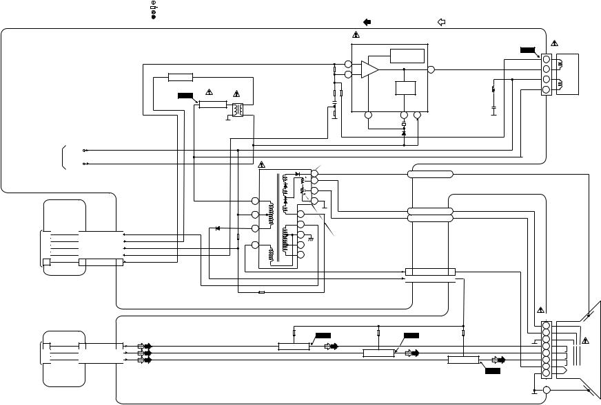
11-7-1
T6450BLCRT
NOTE FOR WIRE CONNECTORS:
1. PREFIX SYMBOL "CN" MEANS CONNECTOR. |
TEST POINT INFORMATION |
|
:INDICATES A TEST POINT WITH A JUMPER WIRE ACROSS A HOLE IN THE PCB. |
||
(CAN DISCONNECT AND RECONNECT.) |
||
2. PREFIX SYMBOL "CL" MEANS WIRE-SOLDER |
:USED TO INDICATE A TEST POINT WITH A COMPONENT LEAD ON FOIL SIDE. |
|
HOLES OF THE PCB. |
:USED TO INDICATE A TEST POINT WITH NO TEST PIN. |
|
(WIRE IS SOLDERED DIRECTLY.) |
:USED TO INDICATE A TEST POINT WITH A TEST PIN. |
|
|
REC VIDEO SIGNAL |
H.V./POWER SUPPLY CBA |
IC551 (V-DEFLECTION CONTROL) |
|
|
|
|
THERMAL |
|
|
|
|
PROTECTION |
|
|
|
7 |
|
5 |
Q533 |
|
AMP |
|
|
H.DRIVE |
|
1 |
|
|
|
|
|
|
|
|
|
|
PUMP |
|
WF12 |
|
|
UP |
|
Q551 |
T552 |
|
|
|
|
|
|
||
|
H.OUTPUT |
|
|
|
|
|
|
VCC |
|
|
|
|
|
|
|
|
6 |
3 |
2 |
PB VIDEO SIGNAL Mode : SP/REC
WF13 |
|
DEFLECTION-YOKE |
|
5 |
V- |
|
|
|
|
4 |
DRIVE |
|
|
|
|
3 |
H- |
|
|
|
|
1 |
DRIVE |
|
|
|
CN551 |
|
|
TO |
+B |
|
|
|
|
POWER SUPPLY |
|
|
|
|
|
BLOCK |
DEF+B |
|
|
T551 F.B.T. |
FOCUS VR |
|
|
|
|||
|
|
|
|
HV |
ANODE |
|
|
|
|
F |
|
|
|
|
|
S |
|
JUNCTION-B |
|
1 |
11 |
|
|
|
|
|
|
||
CBA |
|
|
5 |
8 |
FOCUS |
|
|
|
SCREEN |
||
|
|
|
|
|
|
CL302B |
CN302 |
CN552 |
3 |
10 |
|
|
|
||||
|
2 |
2 |
FBP 2 |
7 |
ANODE |
TO TV |
1 |
1 |
H-DRIVE 1 |
SCREEN VR |
|
|
9 |
|
|||
BLOCK |
5 |
5 |
4 |
|
|
CL302A |
ACL 5 |
|
|
||
4 |
4 |
V-RAMP-FB 4 |
6 |
|
|
|
|
||||
|
3 |
3 |
V-DRIVE 3 |
|
|
CL501A |
|
CL501B |
1 |
HEATER |
1 |
3 |
P-ON+160V |
3 |
|
CL301B |
CN301 |
TO TV |
3 |
3 |
BLOCK |
1 |
1 |
CL301A |
2 |
2 |
|
JUNCTION-C
CBA
|
|
|
|
JK501 |
|
|
|
|
|
FOCUS |
|
|
|
|
|
SCREEN |
|
|
CN502 |
WF14 |
WF15 |
GND |
|
|
Q501 |
Q502 |
|
|
|
RED |
2 |
RED AMP |
|
|
|
|
R |
V501 |
|||
GREEN |
4 |
|
GREEN AMP |
CRT |
|
|
G |
||||
BLUE |
3 |
|
BLUE AMP |
|
|
|
B |
|
|||
|
|
|
Q503 |
|
|
|
|
|
|
|
|
|
|
|
WF16 |
HEATER |
|
|
|
|
|
CN501 |
|
|
|
|
|
GND |
|
CRT CBA
Diagram Block .V.CRT/H

|
|
|
|
|
CAUTION |
|
|
|
|
|
TEST POINT INFORMATION |
|
|
|
|
|
|
|
||
CAUTION ! |
|
|
|
|
|
|
|
|
|
|
:INDICATES A TEST POINT WITH A JUMPER WIRE ACROSS A HOLE IN THE PCB. |
|
||||||||
|
|
|
|
FOR CONTINUED PROTECTION AGAINST FIRE HAZARD, |
|
|
|
:USED TO INDICATE A TEST POINT WITH A COMPONENT LEAD ON FOIL SIDE. |
|
|||||||||||
Fixed voltage power supply circuit is used in this unit. |
|
|
REPLACE ONLY WITH THE SAME TYPE T4A/250V FUSE. |
|
|
|
:USED TO INDICATE A TEST POINT WITH NO TEST PIN. |
|
|
|
||||||||||
If Main Fuse (F601) is blown, check to see that all components in the power supply |
|
|
|
:USED TO INDICATE A TEST POINT WITH A TEST PIN. |
|
|
|
|||||||||||||
|
|
|
|
|
|
|
|
|
|
|||||||||||
NOTE : |
|
|
|
|
|
|
|
|
|
|
|
Comparison Chart |
of Models |
& Marks |
||||||
circuit are not defective before you connect the AC plug to the AC power supply. |
|
|
|
|
|
NOTE FO R WI RE CONNECTORS: |
|
|||||||||||||
Otherwise it may cause some components in the power supply circuit to fail. |
The voltage for parts in hot circuit is measured using |
" |
" = SMD |
|
1. PREFIX SYMBOL "CN" MEANS CONNECTOR. |
Model |
Mark |
Model |
Mark |
|||||||||||
hot GND as a common terminal. |
|
|
|
(CAN DISCONNECT AND RECONNECT.) |
||||||||||||||||
|
|
|
|
|
|
|
|
|
|
|
|
|
|
|||||||
|
|
|
|
|
|
|
|
|
|
|
|
2. PREFIX SYMBOL "CL" MEANS WIRE-SOLDER |
14PV135/07 |
E |
14PV385/01 |
J |
||||
|
|
|
|
HOT |
COLD |
|
|
|
|
|
|
HOLES OF THE PCB. |
|
|
14PV235/07 |
F |
14PV135/58 |
K |
||
|
|
|
|
|
|
|
|
|
|
(WIRE IS SOLDERED DIRECTLY.) |
|
|||||||||
|
|
|
|
|
|
|
|
|
|
|
14PV385/07 |
|
14PV235/58 |
L |
||||||
|
|
|
|
TP503 |
TP504 |
|
|
|
|
|
|
|
|
|
G |
|||||
SW601 |
|
|
|
+B |
GND |
|
|
|
|
|
|
|
|
|
14PV135/01 |
H |
14PV385/39 |
M |
||
POWER |
F601 |
L601 |
D601 - D604 |
T601 |
|
|
|
|
|
|
|
|
|
|
|
14PV235/01 |
I |
|
|
|
|
|
|
|
|
|
|
|
|
|
|
|
|
|
|
||||||
TO |
T4A/250V |
BRIDGE |
|
|
|
|
|
|
|
|
|
|
|
|
|
|
|
|
|
|
|
LINE |
6 |
14 |
|
|
|
|
+B |
|
|
|
|
|
|
|
|
|
|
||
AC-CORD |
|
RECTIFIER |
|
|
|
|
|
|
|
|
|
|
|
|
|
|
||||
|
FILTER |
|
|
|
|
TO |
|
|
|
|
Q206 |
|
|
|
||||||
|
|
|
|
|
|
|
|
|
|
|
|
|
|
|
|
|
||||
|
|
|
|
|
|
|
|
|
|
|
|
|
|
|
|
|
|
|||
|
|
|
|
|
|
|
|
|
|
|
CRT/H.V. |
|
|
|
|
|
|
P-DOWN-L |
|
|
CN601 |
|
|
|
|
|
|
|
|
|
|
BLOCK |
|
|
|
|
|
|
(TO PIN85 OF IC201) |
||
PS602 |
|
|
|
|
|
|
|
DEF+B |
|
|
|
|
|
|
|
|
|
|
||
TO |
|
|
13 |
|
|
|
|
|
|
|
|
|
|
|
|
|
|
|||
DEGAUSSING |
|
|
|
|
|
|
|
|
|
|
|
|
|
|
|
|
G,J,M |
|
|
|
COIL |
|
|
|
|
|
|
|
|
|
|
|
|
|
|
|
|
|
|
|
|
|
|
|
|
|
|
|
|
|
|
|
|
|
|
|
|
|
|
|
|
|
|
|
|
|
|
|
|
|
|
|
|
|
|
|
|
|
|
|
CM+12V/+20.5V |
|
|
|
|
|
|
4 |
12 |
|
|
|
|
|
|
|
|
|
|
|
Q681 |
|
|
|
|
|
|
|
|
|
|
|
|
|
|
|
|
|
|
|
|
|
|
|
|
|
|
|
|
|
|
|
|
|
|
|
|
|
|
|
|
|
|
Q683 |
|
|
|
|
|
|
|
11 |
|
|
|
|
|
|
|
|
|
|
|
|
C-POWER-SW |
|
|
|
|
|
|
|
|
|
|
|
|
|
|
|
|
|
|
|
|
(TO PIN66 OF IC201) |
||
|
|
|
|
|
10 |
|
|
|
|
|
|
|
|
|
|
|
|
|
|
|
12-7-1 |
|
Q602 |
|
|
|
|
|
|
|
|
|
|
|
|
|
|
|
|
|
|
SWITCHING |
|
2 |
|
|
|
|
|
|
CN602 |
|
CN603 |
CL603B |
CL603A |
|
|
|
|
|||
|
|
|
|
9 |
|
|
|
|
|
2 |
AL+20.5V |
2 |
|
2 |
2 |
|
TIMER+5V |
|
||
|
|
|
|
|
|
|
|
|
|
|
|
|
|
|
|
|
||||
|
|
|
|
G,J,M |
|
|
|
|
|
11 AL+33V |
11 |
|
11 |
11 |
|
AL+33V |
|
|
||
|
|
|
|
|
|
|
|
|
|
8 |
AL+9V |
8 |
|
8 |
8 |
|
AL+9V |
|
|
|
|
|
|
|
|
|
|
|
|
|
|
|
|
|
|
||||||
|
|
|
|
1 |
8 |
|
|
|
|
|
7 |
AL+12V(2) |
7 |
|
7 |
7 |
|
AL+12V(2) |
|
|
|
|
|
|
|
|
|
|
|
3 |
AL+12V(1) |
3 |
|
3 |
3 |
|
|
||||
|
|
Q603 |
|
|
Q605 |
Q606 |
|
|
|
|
|
AL+12V(1) |
|
|||||||
|
|
|
|
|
|
|
|
|
|
|
||||||||||
|
|
LIMITER |
|
|
|
|
+5V REG. |
|
|
|
5 |
AL+5V |
5 |
|
5 |
5 |
|
AL+5V |
|
|
|
|
|
|
|
|
|
|
+8V REG. |
12 P-ON+8V |
12 |
|
12 |
12 |
|
P-ON+8V |
|
||||
|
|
|
|
|
|
|
|
|
|
Q682 |
|
|||||||||
|
|
|
|
|
|
|
|
|
|
|
|
|
|
|
6 |
6 |
|
|||
|
|
|
|
|
|
|
|
|
Q607 |
6 |
P-ON-L |
6 |
|
|
P-ON-H |
|
|
|||
|
|
|
|
|
|
|
|
|
|
|
4 |
P-DOWN-L |
4 |
|
4 |
4 |
IC681 |
(TO PIN67 OF IC201) |
|
|
|
|
|
|
|
|
|
|
|
|
|
|
|
|
|
|
|
|
|
|
|
|
|
|
|
|
|
|
|
|
|
|
|
|
JUNCTION-A |
|
+5V |
P-ON+5V(2) |
|
|||
|
|
|
|
|
|
|
|
|
|
|
|
|
|
REG. |
|
|||||
|
|
|
|
4 |
1 |
|
|
|
|
|
|
|
CBA |
|
|
|
|
|
|
|
|
|
|
|
|
|
|
|
|
|
|
|
|
|
|
|
|
|
|||
|
|
|
|
|
|
|
|
|
|
|
|
|
|
|
|
Q684 |
|
|
|
|
|
|
|
|
|
|
Q608 |
|
|
|
|
|
|
|
|
|
|
+5V |
P-ON+5V(3) |
|
|
|
|
|
|
|
|
|
|
|
|
|
|
|
|
|
|
REG. |
|
|||
|
|
|
|
|
|
|
|
|
|
|
|
|
|
|
|
|
|
|||
|
|
|
|
|
|
|
|
|
|
|
|
|
|
|
|
|
|
|
|
|
|
|
|
|
3 |
2 |
|
|
|
|
|
|
|
|
|
|
|
Q686 |
|
|
|
|
|
|
|
|
|
|
|
|
|
|
|
|
|
|
|
|
|
|
|
|
|
|
|
|
IC601 |
|
|
|
|
|
|
|
|
|
|
|
|
+5V |
P-ON+5V(1) |
|
|
|
|
|
|
|
|
|
|
|
|
|
|
|
|
|
|
REG. |
|
|||
|
|
|
|
ERROR |
|
|
|
|
|
|
|
|
|
|
|
|
|
|
|
|
|
|
|
|
|
|
|
|
|
|
|
|
|
|
|
|
|
|
|
|
|
|
|
|
|
VOLTAGE DET |
VR601 |
|
|
|
|
|
|
|
|
|
|
|
|
|
|
|
|
|
|
|
|
Q604 |
|
|
|
|
|
|
|
|
|
IC301 |
|
|
|
||
|
|
|
|
|
+B ADJ. |
|
|
|
|
|
|
|
|
|
|
|
|
|||
|
|
|
|
|
FEED |
|
|
|
|
|
|
|
|
|
|
|
|
|
|
|
|
|
|
|
|
|
|
|
|
|
|
|
|
|
|
|
|
|
|
|
|
|
|
|
|
|
BACK |
|
|
|
|
|
|
|
|
|
|
|
+5.7V P-ON-ON |
|
|
|
|
|
|
|
|
|
|
|
|
|
|
|
|
|
|
|
55 |
|
|
||
|
|
|
|
|
|
|
|
|
|
|
|
|
|
|
|
REG. |
39 |
|
|
|
T6450BLP |
|
|
|
|
|
|
|
|
|
|
|
|
|
TOP |
CL604 |
|
|
|
|
|
|
|
|
|
|
|
|
|
|
|
|
|
|
|
|
|
|
|
|
||
|
|
|
|
|
H.V./POWER S UPPLY |
CBA |
|
|
|
|
|
COVER |
|
|
|
MAIN CBA |
|
|||
|
|
|
|
|
|
|
|
|
|
|
|
|
|
|
|
|
|
|
||
Diagram Block Supply Power
Loading...