


1245
1246
Instruction manual
This instruction manual applies to machines from the
following serial numbers onwards:
PFAFF 1245 # 527 678
PFAFF 1246 # 527 679
296-12-18 401/002
Betriebsanleitung engl. 01.02

This Instruction manual is valid for all models and subclasses listed in the chapter „Specifications“.
The reprinting, copying or translation of PFAFF Instruction Manuals, whether in whole or in part, is only permitted with our previous permission and with written reference to the source.
PFAFF Industrie Maschinen GmbH
Postfach 3020
D-67653 Kaiserslautern
Königstr. 154
D-67655 Kaiserslautern
Editing/Illustrations
Verlag -TD
D - 77901 Lahr

|
|
|
Index |
|
Contents ............................................................................... |
Chapter - Page |
|
1 |
Safety .......................................................................................................................... |
|
1 - 1 |
1.01 |
Directives ..................................................................................................................... |
|
1 - 1 |
1.02 |
General notes on safety ............................................................................................... |
|
1 - 1 |
1.03 |
Safety symbols ............................................................................................................ |
|
1 - 2 |
1.04 |
Important points for the user ....................................................................................... |
|
1 - 2 |
1.05 |
Operating and specialist personnel .............................................................................. |
|
1 - 3 |
1.05.01 |
Operating personnel .................................................................................................... |
|
1 - 3 |
1.05.02 |
Specialist personnel ..................................................................................................... |
|
1 - 3 |
1.06 |
Danger ......................................................................................................................... |
|
1 - 4 |
2 |
Proper use .................................................................................................................. |
|
2 - 1 |
3 |
Specifications ............................................................................................................. |
|
3 - 1 |
3.01 |
PFAFF 1245 ................................................................................................................. |
|
3 - 1 |
3.02 |
Possible models and subclasses ................................................................................. |
|
3 - 1 |
3.03 |
Max. number of stitches/min-1 ...................................................................................................................................................... |
|
3 - 2 |
3.04 |
PFAFF 1246 ................................................................................................................. |
|
3 - 3 |
3.05 |
Possible models and subclasses ................................................................................. |
|
3 - 3 |
3.06 |
Max. number of stitches/min-1 ...................................................................................................................................................... |
|
3 - 4 |
4 |
Disposal of the machine ........................................................................................... |
|
4 - 1 |
5 |
Transport, packaging and storage ........................................................................... |
|
5 - 1 |
5.01 |
Transport to the customer ........................................................................................... |
|
5 - 1 |
5.02 |
Transport within the customer’s premises .................................................................. |
|
5 - 1 |
5.03 |
Disposal of the packaging ............................................................................................ |
|
5 - 1 |
5.04 |
Storage ........................................................................................................................ |
|
5 - 1 |
6 |
Explanation of the symbols ...................................................................................... |
|
6 - 1 |
7 |
Controls ...................................................................................................................... |
|
7 - 1 |
7.01 |
On/off switch ............................................................................................................... |
|
7 - 1 |
7.02 |
Pedals (on machines with subclass -910/01) ............................................................... |
|
7 - 1 |
7.03 |
Pedal (on machines with automatic presser-foot lifter (subclass -910/98) ................... |
7 - 1 |
|
7.04 |
Key on the machine head (for machines with backtacking mechanism -911/97) ......... |
7 - 2 |
|
7.05 |
Lever for lifting the presser foot .................................................................................. |
|
7 - 2 |
7.06 |
Feed regulator / reverse sewing .................................................................................. |
|
7 - 3 |
7.07 |
Feed regulator on machines with backtacking mechanism -911/97 ............................ |
|
7 - 3 |
7.08 |
Adjustment nut for the top-feed stroke ....................................................................... |
|
7 - 4 |

Index
|
Contents ............................................................................... |
Chapter - Page |
|
8 |
Mounting and commissioning the machine ........................................................... |
8 - 1 |
|
8.01 |
Mounting ..................................................................................................................... |
8 |
- 1 |
8.01.01 |
Adjusting the table-top height ...................................................................................... |
8 |
- 1 |
8.01.02 |
Adjusting the V-belt tension ......................................................................................... |
8 |
- 2 |
8.01.03 |
Mounting the upper V-belt guard ................................................................................. |
8 |
- 2 |
8.01.04 |
Mounting the lower V-belt guard ................................................................................. |
8 |
- 3 |
8.01.05 |
Mounting tilt-over safeguard ........................................................................................ |
8 |
- 3 |
8.01.06 |
Mounting the spool holder ............................................................................................. |
8 |
- 4 |
8.01.07 |
Mounting the sewing lamp ........................................................................................... |
8 |
- 4 |
8.02 |
Table top cutout ............................................................................................................ |
8 |
- 5 |
8.02.01 |
PFAFF 1245 .................................................................................................................. |
8 |
- 5 |
8.02.02 |
PFAFF 1246 .................................................................................................................. |
8 |
- 6 |
8.03 |
Commissioning the machine ........................................................................................ |
8 |
- 7 |
8.04 |
Switching the machine on/off ....................................................................................... |
8 |
- 7 |
9 |
Preparation .................................................................................................................. |
9 |
- 1 |
9.01 |
Inserting the needle in the PFAFF 1245 ......................................................................... |
9 |
- 1 |
9.02 |
Inserting the needle in the PFAFF 1246 ......................................................................... |
9 |
- 2 |
9.03 |
Winding the bobbin thread, adjusting the thread tension ............................................... |
9 |
- 2 |
9.04 |
Removing/Threading the bobbin case ........................................................................... |
9 |
- 3 |
9.05 |
Inserting the bobbin case / Adjusting the bobbin thread tension .................................... |
9 |
- 3 |
9.06 |
Threading the needle thread / |
|
|
|
Adjusting the needle thread tension in the PFAFF 1245 ................................................. |
9 |
- 5 |
9.07 |
Threading the needle thread / |
|
|
|
Adjusting the needle thread tension in the PFAFF 1246 .............................................. |
9 |
- 6 |
10 |
Care and maintenance ............................................................................................ |
10 - 1 |
|
10.01 |
Servicing and maintenance intervals .......................................................................... |
10 - 1 |
|
10.02 |
Cleaning ..................................................................................................................... |
10 |
- 1 |
10.03 |
General lubrication ...................................................................................................... |
10 - 2 |
|
10.04 |
Lubricating the hook ................................................................................................... |
10 - 3 |
|
10.05 |
Lubricating the head ................................................................................................... |
10 - 4 |
|
10.06 |
Lubricating the top-feed drive excentric ...................................................................... |
10 - 4 |
|
10.07 |
Checking the air pressure ........................................................................................... |
10 - 5 |
|
10.08 |
Emptying / Cleaning the water container of the air filter .............................................. |
10 - 5 |
|
11 |
Adjustment ............................................................................................................... |
11 |
- 1 |
11.01 |
Tools, gauges and other accessories for adjusting .................................................... |
11 |
- 1 |
11.02 |
Notes on adjusting ..................................................................................................... |
11 |
- 1 |
|
|
|
|

|
|
Index |
|
Contents ............................................................................... |
Chapter - Page |
11.03 |
Abbreviations.............................................................................................................. |
11 - 1 |
11.04 |
Adjusting the basic machine ................................................................................... |
11 - 2 |
11.04.01 |
Positioning the feed dog across the direction of sewing .............................................. |
11 - 2 |
11.04.02 |
Positioning the feed dog in the direction of sewing ..................................................... |
11 - 3 |
11.04.03 |
Height of the bottom feed-dog .................................................................................... |
11 - 4 |
11.04.04 |
Pre-adjusting the needle height ................................................................................... |
11 - 5 |
11.04.05 |
Centering the needle in the needle hole ...................................................................... |
11 - 6 |
11.04.06 |
Lifting motion of the bottom feed-dog ......................................................................... |
11 - 7 |
11.04.07 |
Driving motion of the bottom and top feeds ................................................................ |
11 - 8 |
11.04.08 |
Hook-to-needle clearance, needle rise, needle height and needle guard ...................... |
11 - 9 |
11.04.09 |
Top-feed stroke ............................................................................................................ |
11-11 |
11.04.10 |
Lifting motion of the top feed ....................................................................................... |
11-12 |
11.04.11 |
Bobbin-case opener ..................................................................................................... |
11-13 |
11.04.12 |
Safety clutch ............................................................................................................... |
11-14 |
11.04.13 |
Needle thread tension release ...................................................................................... |
11-15 |
11.04.14 |
Thread check spring .................................................................................................... |
11-16 |
11.04.15 |
Thread check spring on PFAFF 1246 with thread trimmer -900/56 ............................... |
11-17 |
11.04.16 |
Bobbin winder ............................................................................................................. |
11-18 |
11.04.17 |
Presser-foot pressure .................................................................................................. |
11-19 |
11.05 |
Adjusting the thread trimmer -900/56 ........................................................................ |
11-20 |
11.05.01 |
Pre-adjusting the control cam ...................................................................................... |
11-20 |
11.05.02 |
Tripping lever ............................................................................................................... |
11-21 |
11.05.03 |
Pawl ............................................................................................................................ |
11-22 |
11.05.04 |
Engaging solenoid ........................................................................................................ |
11-23 |
11.05.05 |
Release trip ................................................................................................................. |
11-24 |
11.05.06 |
Engaging lever ............................................................................................................. |
11-25 |
11.05.07 |
Linkage rod .................................................................................................................. |
11-26 |
11.05.08 |
Final adjustment of the control cam ............................................................................. |
11-27 |
11.05.09 |
Catch ........................................................................................................................... |
11-28 |
11.05.10 |
Connecting rod (for PFAFF 1246 only) .......................................................................... |
11-29 |
11.05.11 |
Thread-catcher height .................................................................................................. |
11-30 |
11.05.12 |
Knife ............................................................................................................................ |
11-31 |
11.05.13 |
Thread catcher reverse position ................................................................................... |
11-32 |
11.05.14 |
Bobbin-thread clamp spring ......................................................................................... |
11-34 |
11.05.15 |
Tension release bar ..................................................................................................... |
11-36 |
11.05.16 |
Positioner .................................................................................................................... |
11-38 |
12 |
Wearing parts ........................................................................................................... |
12 - 1 |
|
|
|

Safety
1 Safety
1.01Directives
This machine is constructed in accordance with the European regulations contained in the conformity and manufacturer’s declarations.
In addition to this Instruction Manual, observe also all generally accepted, statutory and other regulations and legal requirements -including those of the country and all valid environmental protection regulations!
The regionally valid regulations of the social insurance society for occupational accidents or other supervisory organisations are to be strictly adhered to!
1.02 General notes on safety
●This machine may only be operated by adequately trained operators and only after having completely read and understood the Instruction Manual!
●All Notes on Safety and Instruction Manuals of the motor manufacturer are to be read before operating the machine!
●The danger and safety instructions on the machine itself are to be followed!
●This machine may only be used for the purpose for which it is intended and may not be operated without its safety devices. All safety regulations relevant to its operation are to be adhered to.
●When exchanging sewing tools (e.g. needle, presser foot, needle plate, feed dog or bobbin), when threading the machine, when leaving the machine unattended and during maintenance work, the machine is to be separated from the power supply by switching off the On/Off switch or by removing the plug from the mains!
●Everyday maintenance work is only to be carried out by appropriately trained personnel!
●Repairs and special maintenance work may only be carried out by qualified service staff or appropriately trained personnel!
●When servicing or carrying out repairs on pneumatic devices, the machine is to be removed from the compressed air supply! The only exceptions to this are adjustments and function checks carried out by appropriately trained personnel!
●Work on electrical equipment may only be carried out by appropriately trained personnel!
●Work is not permitted on parts and equipment which are connected to the power supply! Exceptions to this are only to be found in the regulations EN 50110.
●Modifications and alterations to the machine may only be carried out under observance of all the relevant safety regulations!
●Only spare parts which have been approved by us are to be used for repairs! We expressly point out that any replacement parts or accessories which are not supplied by us have not been tested and approved by us. The installation and/or use of any such products can lead to negative changes in the structural characteristics of the machine. We shall not be liable for any damage which may be caused by non-original parts.
1 - 1

Safety
1.03 Safety symbols
Danger!
Points to be observed.
Danger of injury for operating and specialist personnel!
Caution
Do not operate without finger guard and safety devices. Before threading, changing bobbin and needle, cleaning etc. switch off main switch.
 I
I
1.04 Important points for the user
●This Instruction Manual is a component part of the machine and must be available to the operating personnel at all times.
●The Instruction Manual must be read before operating the machine for the first time.
●The operating and specialist personnel is to be instructed as to the safety equipment of the machine and regarding safe work methods.
●It is the duty of the operator to only operate the machine in perfect running order.
●It is the obligation of the operator to ensure that none of the safety mechanisms are removed or deactivated.
●It is the obligation of the operator to ensure that only authorized persons operate and work on the machine.
Further information can be obtained at your PFAFF agent.
1 - 2

Safety
1.05Operating and specialist personnel
1.05.01 Operating personnel
Operating personnel are persons responsible for the equipping, operating and cleaning of the machine as well as taking care of faults arising in the sewing area.
The operating personnel is obliged to observe the following points and must:
●always observe the Notes on Safety in the Instruction Manual!
●never use any working methods which could limit the level of safety in using the machine!
●not wear loose-fitting clothing or jewellery such as chains or rings!
●also ensure that only authorized persons operate the machine.
●always immediately report to the user any changes in the machine which may limit its safety!
1.05.02 Specialist personnel
Specialist personnel are persons with a specialist education in the fields of electrics, electronics and mechanics. They are responsible for the lubrication, maintenance, repair and adjustment of the machine.
The specialist personnel is obliged to observe the following points and must:
●always observe the Notes on Safety in the Instruction Manual!
●switch off the On/Off switch before carrying out adjustments or repairs and ensure that it cannot be switched on again unintentionally!
●never work on parts which are still connected to the power supply! Exceptions are contained only in the regulations EN 50110.
●when servicing or carrying out repairs on pneumatic devices, remove the machine from the compressed air supply! The only exceptions to this are function checks.
●replace the protective coverings and close the electrical control box after all repairs or maintenance work!
1 - 3
Safety
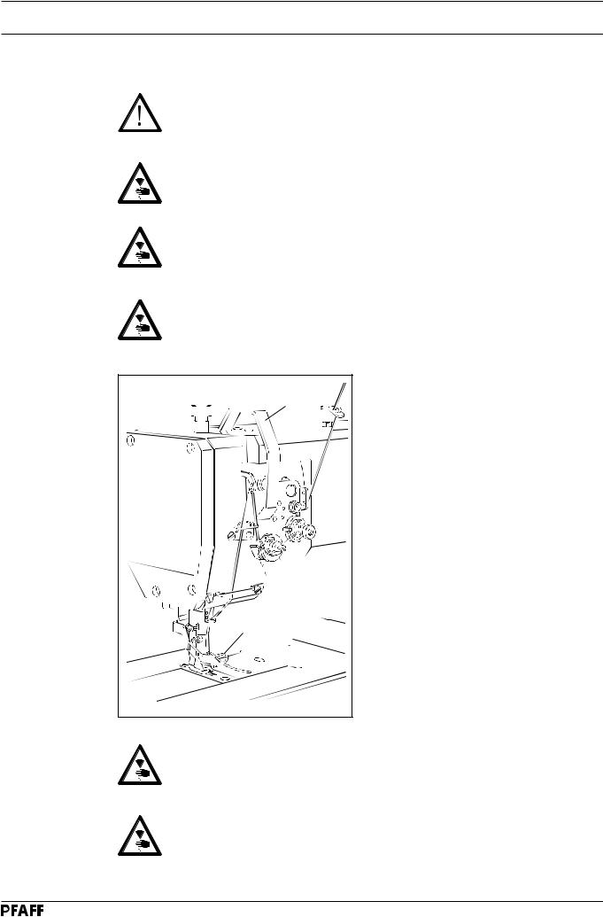
1.06 Danger
A working area of 1 metre is to be kept free both in front of and behind the machine while it is in operation so that it is always easily accessible.
Never reach into the sewing area while sewing! Danger of injury by the needle!
Never leave objects on the table or in the needle plate area while adjusting the machine settings! Objects can become trapped or be slung away! Danger of injury!
On mechanically activated clutch motors without an actuating lock, wait until the motor has come to a standstill! Danger of injury!
1 |
2 |
Fig. 1 - 01 |
Do not operate the machine without the take-up lever guard 1!
Danger of injury due to the movement of the take-up lever!
Do not operate the machine without the finger guard 2!
Danger of injury by the moving needle!
1 - 4

Safety
|
Do not operate the machine |
|
without tilt-back safeguard 3! |
|
Danger of crushing between |
|
upper part and table top! |
Fig.1 - 02 |
3 |
4
5
Fig. 1 - 03
Do not operate the machine without belt guards 4 and 5! Danger of injury by the revolving V-belt!
1 - 5
Proper use
2Proper use
PFAFF 1245
The PFAFF 1245 is a single needle, flatbed sewing machine with bottom, top and needle feeds as well as a large vertical hook for sewing lockstitch seams. The machine is designed for commercial use (industry).
PFAFF 1246
The Pfaff 1246 is a two-needle, flat bed sewing machine with bottom, top and needle feed as well as vertical sewing hook for lockstitch seams. The machine is intended for commercial (industrial) use only.
Any and all uses of this machine which have not been approved of by the manufacturer are considered to be inappropriate! The manufacturer cannot be held liable for any damage caused by the inappropriate use of the machine! The appropriate use of the machine includes the observance of all operational, adjustment, maintenance and repair measures required by the manufacturer!
2 - 1

Specifications
3Specifications
3.01 |
PFAFF 1245 |
|
|
Stitch type: ........................................................................................................ |
301 (lockstitch) |
|
Needle system: .............................................................................................................. |
134-35 |
|
Needle thickness in 1/100 mm: |
|
|
Model C: ..................................................................................................................... |
110 - 140 |
|
Max. thread thickness (synthetic ▲ ): |
|
|
Model C: ........................................................................................................................... |
20/3 |
|
Max. stitch length: |
|
|
Model N: ...................................................................................................................... |
6.0 mm |
|
Model N8: .................................................................................................................... |
8.0 mm |
|
Handwheel eff. dia.: ...................................................................................................... |
80 mm |
|
Max. speed: ................................................................................................... |
see chapter 3.03 |
|
Dimensions of machine: |
|
|
Length: ........................................................................................................... |
approx. 570 mm |
|
Width: ............................................................................................................. |
approx. 177 mm |
|
Height: ............................................................................................................ |
approx. 410 mm |
|
Clearance width: ......................................................................................................... |
265 mm |
|
Clearance height: ......................................................................................................... |
115 mm |
|
Fabric clearance (presser foot raised): .......................................................................... |
14 mm |
|
Net weight (machine head): ................................................................................ |
approx. 40 kg |
|
Power supply: .......................................................................... |
190 - 240 V 50 / 60 Hz, 1 phase |
|
Power consumption: ............................................................................................. |
max. 600 VA |
|
Fuse protection: .................................................................................. |
1 x 16 A, delayed action |
|
Working air pressure: ....................................................................................................... |
6 bar |
|
Air consumption: ......................................................................................... |
~0.8 l / work cycle |
|
Working noise level: |
|
|
Emission at workplace |
|
|
n = 2300 spm: ........................................................................................................... |
82 dB (A) |
|
Noise measurement in accordance with DIN 45 635-48-A-1 |
|
Subject to alteration
▲Or comparable thicknesses of other thread types
3.02 |
Possible models and subclasses |
|
|
Model C: ................................................................... |
For processing medium-heavy materials |
|
Additional equipment: |
|
|
Subclass -900/56 .............................................................................................. |
Thread trimmer |
|
Subclass -910/ ............................................................................... |
Automatic presser-foot lifter |
|
Subclass -911/ ............................................................................................................ |
Bartacker |
|
|
|
3 - 1 |
|
|

Specifications
3.03 Max. number of stitches/min-1
Top feed lift |
Max. number of |
Max. number of |
|
stitches/min-1 for |
stitches/min-1 for stitch |
|
stitch lengths up to 6 mm |
lengths from 6 mm to 8 mm |
|
|
|
less than 3.5 mm |
2800 |
2600 |
|
|
|
from 3.5 to 5.5 mm |
2500 |
2500 |
|
|
|
from 5.5 to 7 mm |
2000 |
2000 |
|
|
|
3 - 2

Specifications
3.04 |
PFAFF 1246 |
|
|
Stitch type: ........................................................................................................ |
301 (lockstitch) |
|
Needle system: .............................................................................................................. |
134-35 |
|
Needle thickness in 1/100 mm: |
|
|
Model B: ...................................................................................................................... |
80 - 100 |
|
Model C: ..................................................................................................................... |
110 - 140 |
|
Max. thread thickness (synthetic ▲ ): |
|
|
Model B: ........................................................................................................................... |
40/3 |
|
Model C: ........................................................................................................................... |
20/3 |
|
Max. stitch length: |
|
|
Model BN and CN: ....................................................................................................... |
6.0 mm |
|
Model CN8: .................................................................................................................. |
8.0 mm |
|
Handwheel eff. dia.: ...................................................................................................... |
80 mm |
|
Max. speed: ................................................................................................... |
see chapter 3.06 |
|
Dimensions of machine: |
|
|
Length: ........................................................................................................... |
approx. 570 mm |
|
Width: ............................................................................................................. |
approx. 177 mm |
|
Height: ............................................................................................................ |
approx. 410 mm |
|
Clearance width: ......................................................................................................... |
265 mm |
|
Clearance height: ......................................................................................................... |
115 mm |
|
Fabric clearance (presser foot raised): .......................................................................... |
14 mm |
|
Net weight (machine head): ................................................................................ |
approx. 40 kg |
|
Power supply: .......................................................................... |
190 - 240 V 50 / 60 Hz, 1 phase |
|
Power consumption: ............................................................................................. |
max. 600 VA |
|
Fuse protection: .................................................................................. |
1 x 16 A, delayed action |
|
Working air pressure: ....................................................................................................... |
6 bar |
|
Air consumption: ......................................................................................... |
~0.8 l / work cycle |
|
Working noise level: |
|
|
Emission at workplace |
|
|
n = 2200 spm: ........................................................................................................... |
82 dB (A) |
|
Noise measurement in accordance with DIN 45 635-48-A-1 |
|
Subject to alteration
▲Or comparable thicknesses of other thread types
3.05 |
Possible models and subclasses |
|
|
Model B: .............................................................................. |
For processing medium materials |
|
Model C: ................................................................... |
For processing medium-heavy materials |
|
Additional equipment: |
|
|
Subclass -900/56 .............................................................................................. |
Thread trimmer |
|
Subclass -910/04 ........................................................................... |
Automatic presser-foot lifter |
|
Subclass -911/35 ........................................................................................................ |
Bartacker |
3 - 3

Specifications
3.06 |
Max. number of stitches/min-1 |
|
|
|
|
|
|
|
|||
|
|
|
|
|
|
|
|
|
|
|
|
|
|
Top feed lift |
Max. number of stitches/min-1 for stitch lengths up to 6 mm and |
needle gauge of up to 10 mm |
Max. number of stitches/min-1 for stitch lengths up to 6 mm and |
needle gauge of more than 10 mm |
Max. number of stitches/min-1 for |
stitch lengths from 6 mm to 8 mm and needle gauge of up to 10 mm |
Max. number of stitches/min-1 for |
stitch lengths up to 6 mm to 8 mm and needle gauge of more than |
10 mm |
|
|
|
|
|
|
|
|
|
|
|
|
|
|
less than 3.5 mm |
2700 |
|
2500 |
|
|
2500 |
|
2300 |
|
|
|
|
|
|
|
|
|
|
|
|
|
|
|
from 3.5 to 5.5 mm |
2400 |
|
2200 |
|
|
2400 |
|
2100 |
|
|
|
|
|
|
|
|
|
|
|
|
|
|
|
from 5.5 to 7 mm |
1900 |
|
1700 |
|
|
1900 |
|
1600 |
|
|
|
|
|
|
|
|
|
|
|
|
|
3 - 4

Disposal of the machine
4Disposal of machine waste
●The proper disposal of machine waste is the responsibility of the customer.
●The materials used on the machines are steel, aluminium, brass and various plastics. The electrical equipment consists of plastics and copper.
●The machine waste is to be disposed of in accordance with the locally valid environmental protection regulations. If necessary a specialist is to be commissioned.
Special care is to be taken that parts soiled with lubricants are separately disposed of in accordance with the locally valid pollution control regulations!
4 - 1

|
Transport packaging and storage |
5 |
Transport packaging and storage |
5.01 |
Transport to the customer’s premises |
|
Within the Federal Republic of Germany, the machine is delivered without packaging. |
|
Machines for export are packaged in a crate or wrapped depending on how they are |
|
transported. |
5.02 |
Transport within the customer’s premises |
|
The manufacturer carries no liability for transport within the customer’s premises. Care is |
|
to be taken to transport the machine in an upright position only. |
5.03 |
Disposal of the packaging |
|
The packaging of the machine consists of wood, paper, cardboard and VCE fibre. The proper |
|
disposal of the packaging is the responsibility of the customer. |
5.04 |
Storage |
|
The machine can be stored for up to 6 months if not in use. During this time it should be |
|
protected from dust and moisture. |
For longer storage the individual parts of the machine, especially the moving parts, should be protected against corrosion e.g. by a film of oil.
5 - 1 |
5 - 1 |
Explanation of the symbols
6 Explanation of the symbols
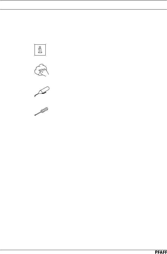
In the following section of this Instruction Manual, certain tasks or important pieces of information are accentuated by symbols.
The symbols used have the following meanings:
Note, information
Cleaning, care
Lubrication, greasing
Servicing, repairing, adjustment, maintenance
(only to be carried out by specialist personnel)
6 - 1
Controls
7Controls
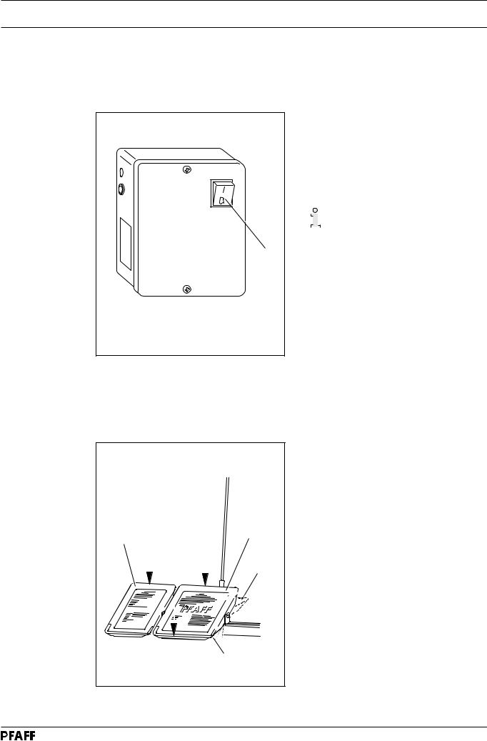
7.01 |
On/off switch |
● Turn the machine on and off by switching the on/off switch 1 on and off. When the machine is on, the light in the switch is also on.
|
|
|
|
|
|
The switch in the illustration can |
|
|
|
|
|
|
be found on machines with Quick |
|
|
|
|
|
|
|
|
|
|
|
|
|
motors. When other motors are |
|
|
|
|
|
|
|
|
|
|
|
|
|
used, the switch may not look |
|
|
|
|
|
|
|
|
|
|
|
|
|
|
1 |
|
|
|
|
|
the same. |
|
|
|
|
|
|
|
Fig. 7 - 01 |
|
|
|
7.02 |
Pedals (on machines with subclas -910/01) |
|
|
|
|
|
|
With the on/off switch on |
|
|
|
|
0 = |
Machine stop |
|
|
|
+1 = |
Sew |
|
|
|
- 1 = |
Trim thread (on machines with thread |
|
|
|
|
trimmer) |
|
+2 |
0 |
+2 = |
Raise presserfoot |
|
|
|
|
|
|
|
+1 |
|
|
|
|
- 1 |
|
|
|
Fig. 7 - 02 |
|
|
|
|
|
|
|
7 - 1 |

Controls
7.03 |
Pedal (on machines with automatic presser-foot lifter -910/98) |
||||
|
|
|
|
With the on/off switch on |
|
|
|
|
|
||
|
|
|
0 = |
Machine stop |
|
|
|
|
+1 = |
Sew |
|
|
0 |
- 1 = |
Raise presserfoot |
||
|
|
|
- 2 = |
Trim thread (on machines with thread |
|
|
|
|
+1 |
|
trimmer) |
|
|
|
|
||
|
|
|
|
|
|
|
|
|
|
|
|
- 1 - 2
Fig. 7 - 03
7.04 |
Key on the machine head (for machines with backtacking mechanism -911/97) |
1 |
Fig. 7 - 04 |
●Switch to reverse sewing by pressing key 1 while sewing.
7 - 2
Controls
7.05 Lever for lifting the presser foot
1 |
Fig. 7 - 05 |
●The sewing foot can be lifted by raising lever 1.
7.06 Feed regulator / reverse sewing
● Adjust the stitch length by turning the knurled nut 1 accordingly.
Reverse sewing
● Press knurled nut 1 upwards as far as
possible (position „R“).
R
 1
1
Fig. 7 - 06
7 - 3

Controls
7.07 |
Feed regulator (on machines with backtacking mechanism -911/97) |
2 |
1 |
Fig. 7 - 07 |
You can set the length of the reverse stitch as large as is required, independent of the forward stitch.
●The forward stitch is set with knurled screw 1 and the reverse stitch with knurled screw 2.
The options for setting the automatic start and end bartacks are to be found in the instruction manual of the motor.
7.08 Adjustment nut for the top-feed stroke
Turn the machine off!
1
● Open cover 1 on the back of the machine, loosen screw 2 and move as required.
 2
2
Fig. 7 - 08
7 - 4

Mounting and commissioning the machine
8 |
Mounting and commissioning the machine |
The machine must only be mounted and commissioned by qualified personnel!
All relevant safety regulations are to be observed!
If the machine is delivered without a table, it must be ensured that the frame and the table top which you intend to use can hold the weight of the machine and the motor, even while sewing.
8.01 Mounting
The necessary electricity and compressed air supplies must be available at the machine’s location (see specifications).
A stable and horizontal surface as well as sufficient illumination at the machine’s location.
Due to reasons of packaging, the table top is lowered for transport. The following is a description of how to adjust the height of the table top.
8.01.01 Adjusting the table-top height
1 |
3 |
1 |
|
2 |
|
Fig. 8 - 01
●Loosen screws 1 and 2.
●Set the desired table-top height and tighten screws 1 well.
●Adjust the position of the right pedal so that you can operate it comfortably and tighten screw 2.
●The setting of the left pedal can be adjusted with chain 3. (This adjustment is not necessary on machines with an automatic presser-foot lifter)
8 - 1

Mounting and commissioning the machine
8.01.02 Adjusting the V-belt tension
2 |
cm |
|
|
|
1 |
|
2 |
Fig. 8 - 02 |
|
●Loosen nuts 1.
●Tighten the V-belt with belt take-up hanger 2.
●Tighten nuts 1.
Fig. 8 - 02 shows a Quick motor. If another motor is used, proceed as described in the motor’s instruction manual.
8.01.03 |
Mounting the upper V-belt guard |
|
|
|
If a large balance wheel is used, |
|
|
the corner 1 of the belt guard 3 |
|
1 |
must be broken out. |
|
|
|
|
|
● Screw position stop 2 to the belt guard |
|
3 |
section 3. |
|
● Attach belt guard section 3. |
|
|
|
|
|
2 |
● Attach belt guard section 4. |
|
|
|
|
4 |
|
|
Fig. 8 - 03 |
|
8 - 2

Mounting and commissioning the machine
8.01.04 Mounting the lower V-belt guard
8 |
7 |
8 |
Fig. 8 - 04 |
●Align belt-guard 7 in such a way that both the motor pulley and the V-belt run freely.
●Tighten screws 8.
Fig. 8 - 04 shows a Quick motor. If another motor is used, proceed as described in the motor’s instruction manual.
8.01.05 |
Mounting tilt-over safeguard |
|
|
|
|
|
● Screw-mount tilt-over safeguard 1 |
|
|
|
included in the accessories with screw 2. |
|
|
|
Do not operate the machine |
|
|
|
without tilt-over safeguard 1! |
|
|
|
Danger of crushing between |
|
|
2 |
upper part and table top! |
|
Fig. 8 - 06 |
1 |
|
|
|
|
|
8 - 3
 Loading...