


 Loading...
okuma OSP-P200M, OSP-P200MA, OSP-P20M, OSP-P200M-R, OSP-P200MA-R Programming Manual
...CNC SYSTEM
OSP-P200M/P200MA/P20M OSP-P200M-R/P200MA-R/P20M-R
PROGRAMMING MANUAL
(10th Edition)
Pub No. 5228-E-R9 (ME33-018-R10) Oct. 2010

5228-E P-(i)
SAFETY PRECAUTIONS
SAFETY PRECAUTIONS
The machine is equipped with safety devices which serve to protect personnel and the machine itself from hazards arising from unforeseen accidents. However, operators must not rely exclusively on these safety devices: they must also become fully familiar with the safety guidelines presented below to ensure accidentfree operation.
This instruction manual and the warning signs attached to the machine cover only those hazards which Okuma can predict. Be aware that they do not cover all possible hazards.
1.Precautions Relating to Installation
(1)Please be noted about a primary power supply as follows.
•Do not draw the primary power supply from a distribution panel that also supplies a major noise source (for example, an electric welder or electric discharge machine) since this could cause malfunction of the CNC unit.
•If possible, connect the machine to a ground not used by any other equipment. If there is no choice but to use a common ground, the other equipment must not generate a large amount of noise (such as an electric welder or electric discharge machine).
(2)Installation Environment
Observe the following points when installing the control enclosure.
•Make sure that the CNC unit will not be subject to direct sunlight.
•Make sure that the control enclosure will not be splashed with chips, water, or oil.
•Make sure that the control enclosure and operation panel are not subject to excessive vibrations or shock.
•The permissible ambient temperature range for the control enclosure is 5 to 40°C.
•The permissible ambient humidity range for the control enclosure is relative humidity 50% or less at 40°C (no condensation).
•The maximum altitude at which the control enclosure can be used is 1000 m (3281ft.).
2.Points to Check before Turning on the Power
(1)Close all the doors of the control enclosure and operation panel to prevent the entry of water, chips, and dust.
(2)Make absolutely sure that there is nobody near the moving parts of the machine, and that there are no obstacles around the machine, before starting machine operation.
(3)When turning on the power, turn on the main power disconnect switch first, then the CONTROL ON switch on the operation panel.

5228-E P-(ii)
SAFETY PRECAUTIONS
3.Precautions Relating to Operation
(1)After turning on the power, carry out inspection and adjustment in accordance with the daily inspection procedure described in this instruction manual.
(2)Use tools whose dimensions and type are appropriate for the work undertaken and the machine specifications. Do not use badly worn tools since they can cause accidents.
(3)Do not, for any reason, touch the spindle or tool while spindle indexing is in progress since the spindle could rotate: this is dangerous.
(4)Check that the workpiece and tool are properly secured.
(5)Never touch a workpiece or tool while it is rotating: this is extremely dangerous.
(6)Do not remove chips by hand while machining is in progress since this is dangerous. Always stop the machine first, then remove the chips with a brush or broom.
(7)Do not operate the machine with any of the safety devices removed. Do not operate the machine with any of the covers removed unless it is necessary to do so.
(8)Always stop the machine before mounting or removing a tool.
(9)Do not approach or touch any moving part of the machine while it is operating.
(10)Do not touch any switch or button with wet hands. This is extremely dangerous.
(11)Before using any switch or button on the operation panel, check that it is the one intended.
4.Precautions Relating to the ATC
(1)The tool clamps of the magazine, spindle, etc., are designed for reliability, but it is possible that a tool could be released and fall in the event of an unforeseen accident, exposing you to danger: do not touch or approach the ATC mechanism during ATC operation.
(2)Always inspect and change tools in the magazine in the manual magazine interrupt mode.
(3)Remove chips adhering to the magazine at appropriate intervals since they can cause misoperation. Do not use compressed air to remove these chips since it will only push the chips further in.
(4)If the ATC stops during operation for some reason and it has to be inspected without turning the power off, do not touch the ATC since it may start moving suddenly.
5.On Finishing Work
(1)On finishing work, clean the vicinity of the machine.
(2)Return the ATC, APC and other equipment to the predetermined retraction position.
(3)Always turn off the power to the machine before leaving it.
(4)To turn off the power, turn off the CONTROL ON switch on the operation panel first, then the main power disconnect switch.

5228-E P-(iii)
SAFETY PRECAUTIONS
6.Precautions during Maintenance Inspection and When Trouble Occurs
In order to prevent unforeseen accidents, damage to the machine, etc., it is essential to observe the following points when performing maintenance inspections or during checking when trouble has occurred.
(1)When trouble occurs, press the emergency stop button on the operation panel to stop the machine.
(2)Consult the person responsible for maintenance to determine what corrective measures need to be taken.
(3)If two or more persons must work together, establish signals so that they can communicate to confirm safety before proceeding to each new step.
(4)Use only the specified replacement parts and fuses.
(5)Always turn the power off before starting inspection or changing parts.
(6)When parts are removed during inspection or repair work, always replace them as they were and secure them properly with their screws, etc.
(7)When carrying out inspections in which measuring instruments are used - for example voltage checks - make sure the instrument is properly calibrated.
(8)Do not keep combustible materials or metals inside the control enclosure or terminal box.
(9)Check that cables and wires are free of damage: damaged cables and wires will cause current leakage and electric shocks.
(10)Maintenance inside the Control Enclosure
a.Switch the main power disconnect switch OFF before opening the control enclosure door.
b.Even when the main power disconnect switch is OFF, there may some residual charge in the MCS drive unit (servo/spindle), and for this reason only service personnel are permitted to perform any work on this unit. Even then, they must observe the following precautions.
•MCS drive unit (servo/spindle)
The residual voltage discharges two minutes after the main switch is turned OFF.

5228-E P-(iv)
SAFETY PRECAUTIONS
c.The control enclosure contains the NC unit, and the NC unit has a printed circuit board whose memory stores the machining programs, parameters, etc. In order to ensure that the contents of this memory will be retained even when the power is switched off, the memory is supplied with power by a battery. Depending on how the printed circuit boards are handled, the contents of the memory may be destroyed and for this reason only service personnel should handle these boards.
(11)Periodic Inspection of the Control Enclosure
a.Cleaning the cooling unit
The cooling unit in the door of the control enclosure serves to prevent excessive temperature rise inside the control enclosure and increase the reliability of the NC unit. Inspect the following points every three months.
•Is the fan motor inside the cooling unit working?
The motor is normal if there is a strong draft from the unit.
•Is the external air inlet blocked?
If it is blocked, clean it with compressed air.
7.General Precautions
(1)Keep the vicinity of the machine clean and tidy.
(2)Wear appropriate clothing while working, and follow the instructions of someone with sufficient training.
(3)Make sure that your clothes and hair cannot become entangled in the machine. Machine operators must wear safety equipment such as safety shoes and goggles.
(4)Machine operators must read the instruction manual carefully and make sure of the correct procedure before operating the machine.
(5)Memorize the position of the emergency stop button so that you can press it immediately at any time and from any position.
(6)Do not access the inside of the control panel, transformer, motor, etc., since they contain highvoltage terminals and other components which are extremely dangerous.
(7)If two or more persons must work together, establish signals so that they can communicate to confirm safety before proceeding to each new step.

5228-E P-(v)
SAFETY PRECAUTIONS
8.Symbols Used in This Manual
The following warning indications are used in this manual to draw attention to information of particular importance. Read the instructions marked with these symbols carefully and follow them.

 DANGER
indicates an imminently hazardous situation which, if not avoided, will result in death or serious injury.

 WARNING
indicates a potentially hazardous situation which, if not avoided, could result in death or serious injury.

 CAUTION
indicates a potentially hazardous situation which, if not avoided, may result in minor or moderate injury.

 CAUTION
indicates a potentially hazardous situation which, if not avoided, may result in damage to your property.
SAFETYINSTRUCTIONS
indicates general instructions for safe operation.

5228-E P-(i)
INTRODUCTION
INTRODUCTION
Thank you very much for choosing our NC system. This NC system is an expandable CNC with various features. Major features of the NC system are described below.
(1)Compact and highly reliable
The CNC system has become compact and highly reliable because of advanced hardware technology, including the computer boards equipped with high-speed microprocessors, I/O link, and servo link. The "variable software" as a technical philosophy of the OSPs supported by a flash memory. Functions may be added to the CNC system as required after delivery.
(2)NC operation panels
The following types of NC operation panels are offered to improve the user-friendliness.
•Thin color operation panels (horizontal)
•Thin color operation panels (vertical)
One or more of the above types may not be used for some models.
(3)Machining management functions
These functions contribute to the efficient operation of the CNC system and improve the profitability from small quantity production of multiple items and variable quantity production of variations. Major control functions are described below.
a.Reduction of setup time
With increase in small-volume production, machining data setting is more frequently needed. The simplified file operation facilitates such troublesome operation. The documents necessary for setup, such as work instructions, are displayed on the CNC system to eliminate the necessity of controlling drawings and further reduce the setup time.
b.Production Status Monitor
The progress and operation status can be checked on a real-time basis on the screen of the CNC system.
c.Reduction of troubleshooting time
Correct information is quickly available for troubleshooting.
(4)Help functions
When an alarm is raised, press the help key to view the content of the alarm. This helps take quick action against the alarm.
To operate the CNC system to its maximum performance, thoroughly read and understand this instruction manual before use.
Keep this instruction manual at hand so that it will be available when you need a help.
Screens
Different screens are used for different models. Therefore, the screens used on your CNC system may differ from those shown in this manual.

5228-E P-(i)
TABLE OF CONTENTS
TABLE OF CONTENTS
SECTION 1 PROGRAM CONFIGURATIONS ............................................................. |
1 |
|
1. |
Program Types and Extensions............................................................................................... |
1 |
2. |
Program Name ........................................................................................................................ |
2 |
3. |
Sequence Name ...................................................................................................................... |
3 |
4. |
Program Format....................................................................................................................... |
4 |
|
4-1. Word Configuration........................................................................................................... |
4 |
|
4-2. Block Configuration .......................................................................................................... |
4 |
|
4-3. Program............................................................................................................................ |
5 |
|
4-4. Programmable Range of Address Characters.................................................................. |
5 |
5. |
Mathematical Operation Functions .......................................................................................... |
6 |
6. |
Optional Block Skip.................................................................................................................. |
8 |
7. |
Program Branch Function (Optional) ....................................................................................... |
9 |
8. |
Comment Function (Control OUT/IN) ...................................................................................... |
9 |
9. |
Message Function (Optional)................................................................................................. |
10 |
10.Operation Methods and Program Storage Memory Capacity................................................ |
10 |
|
SECTION 2 COORDINATE SYSTEMS AND COORDINATE COMMANDS ............. |
13 |
|
1. |
Coordinate System ................................................................................................................ |
13 |
|
1-1. Coordinate Systems and Values .................................................................................... |
13 |
|
1-2. Machine Zero and Machine Coordinate System ............................................................ |
13 |
|
1-3. Work Coordinate System................................................................................................ |
14 |
|
1-4. Local Coordinate System ............................................................................................... |
14 |
2. |
Coordinate Commands.......................................................................................................... |
15 |
|
2-1. Numerically Controlled Axes .......................................................................................... |
15 |
|
2-2. Unit Systems .................................................................................................................. |
16 |
|
2-3. Travel Limit Commands (G22, G23) (Optional).............................................................. |
21 |
|
2-4. Home Position Command (G30) .................................................................................... |
23 |
|
2-5. Absolute and Incremental Commands (G90, G91) ........................................................ |
24 |
|
2-6. Coordinate Recalculation Command (G97).................................................................... |
25 |
SECTION 3 FEED FUNCTIONS................................................................................ |
26 |
|
1. |
Rapid Feed ............................................................................................................................ |
26 |
2. |
Cutting Feed .......................................................................................................................... |
26 |
|
2-1. Feed per Minute (G94) ................................................................................................... |
26 |
|
2-2. Feed per Revolution (G95) ............................................................................................. |
26 |
|
2-3. F1-digit Feed Function (Optional)................................................................................... |
27 |
|
2-4. F0 Command During Cutting Feed................................................................................. |
28 |
3. |
Exact Stop Check Function (G09, G61, G64)........................................................................ |
29 |
4. |
Automatic Acceleration and Deceleration.............................................................................. |
30 |

|
|
5228-E P-(ii) |
|
TABLE OF CONTENTS |
|
5. |
Following Error Check ........................................................................................................... |
31 |
6. |
Positioning (G00) ................................................................................................................... |
32 |
7. |
Uni-directional Positioning (G60) ........................................................................................... |
33 |
8. |
Linear Interpolation (G01)...................................................................................................... |
34 |
9. |
Plane Selection (G17, G18, G19) .......................................................................................... |
35 |
10.Circular Interpolation (G02, G03)........................................................................................... |
37 |
|
11.Helical Cutting (G02, G03) (Optional).................................................................................... |
40 |
|
SECTION 4 PREPARATORY FUNCTIONS............................................................... |
41 |
|
1. |
Dwell Command (G04) .......................................................................................................... |
41 |
2. |
Programmable Mirror Image (G62) (Optional)....................................................................... |
42 |
3. |
Work Coordinate System Selection (G15, G16) .................................................................... |
44 |
4. |
Work Coordinate System Change (G92) ............................................................................... |
45 |
5. |
Unit System Check (G20, G21) (Optional) ............................................................................ |
45 |
6. |
Coordinate System Conversion Functions ............................................................................ |
46 |
|
6-1. Parallel Shift and Rotation of Coordinate Systems (G11, G10)...................................... |
46 |
|
6-2. Copy Function (COPY, COPYE) .................................................................................... |
48 |
7. |
Workpiece Geometry Enlargement / Reduction Function (G51, G50) (Optional).................. |
50 |
SECTION 5 S, T, AND M FUNCTIONS ..................................................................... |
52 |
|
1. |
S Code Function .................................................................................................................... |
52 |
2. |
T Code Function .................................................................................................................... |
52 |
3. |
M Code Function ................................................................................................................... |
53 |
|
3-1. Examples of M Codes .................................................................................................... |
53 |
SECTION 6 OFFSET FUNCTIONS ........................................................................... |
56 |
|
1. |
Tool Length Offset Function (G53 - G59) .............................................................................. |
56 |
2. |
Cutter Radius Compensation (G40, G41, G42)..................................................................... |
57 |
|
2-1. Cutter Radius Compensation Function........................................................................... |
57 |
|
2-2. Tool Movement in Start-up ............................................................................................. |
59 |
|
2-3. Tool Movement in Cutter Radius Compensation Mode.................................................. |
62 |
|
2-4. Tool Movement when Cutter Radius Compensation is Canceled .................................. |
67 |
|
2-5. Changing Compensation Direction in Cutter Radius Compensation Mode.................... |
71 |
|
2-6. Cutter Radius Compensation Type A ............................................................................. |
74 |
|
2-7. Notes on Cutter Radius Compensation .......................................................................... |
81 |
3. |
Cutter Radius Compensation Mode Override Function ......................................................... |
90 |
|
3-1. Automatic Override at Corners ....................................................................................... |
90 |
|
3-2. Circular Arc Inside Cutting Override ............................................................................... |
92 |
4. |
Tool Radius Compensation G39 Command .......................................................................... |
93 |
|
4-1. Parameter....................................................................................................................... |
93 |
|
4-2. Corner Circular Interpolation .......................................................................................... |
94 |
|
4-3. Corner Circular Interpolation Command Automatic Insertion ......................................... |
96 |

|
|
5228-E P-(iii) |
|
TABLE OF CONTENTS |
|
5. |
Three-dimensional Tool Offset (G43, G44) (Optional)........................................................... |
98 |
|
5-1. Three-dimensional Tool Offset Start-up ......................................................................... |
98 |
|
5-2. Three-dimensional Tool Offset Vector............................................................................ |
99 |
|
5-3. Canceling Three-dimensional Tool Offset .................................................................... |
101 |
|
5-4. Actual Position Data Display And Feedrate.................................................................. |
101 |
|
5-5. Relationship with Other G Functions ............................................................................ |
102 |
|
5-6. Relationship to Other Tool Offset Functions................................................................. |
102 |
SECTION 7 FIXED CYCLES ................................................................................... |
103 |
|
1. |
Table of Fixed Cycle Functions ........................................................................................... |
104 |
2. |
Fixed Cycle Operations ....................................................................................................... |
105 |
|
2-1. Determining the Positioning Plane and the Cycle Axis................................................. |
106 |
|
2-2. Controlling the Return Level ......................................................................................... |
107 |
|
2-3. Fixed Cycle Mode......................................................................................................... |
107 |
|
2-4. Cycle Operation Conditions.......................................................................................... |
108 |
3. |
General Rules for Programming Fixed Cycles .................................................................... |
109 |
|
3-1. Programming Format (General Command Format) ..................................................... |
109 |
|
3-2. Command Items Necessary for Fixed Cycle Function Commands .............................. |
111 |
|
3-3. Absolute Programming Mode and Incremental Programming Mode............................ |
112 |
|
3-4. Positional Relationship among Return Point Level, Point R Level and Point Z |
|
|
Level ............................................................................................................................. |
113 |
|
3-5. Axis Shift....................................................................................................................... |
113 |
|
3-6. Z-axis G01 Mode Return Function ............................................................................... |
114 |
|
3-7. Relationships between Fixed Cycle Functions and Other Functions ........................... |
115 |
|
3-8. Notes for Programming a Fixed Cycle.......................................................................... |
116 |
4. |
Specification of Return-point Level (G71)............................................................................ |
117 |
5. |
High Speed Deep Hole Drilling Cycle (G73)........................................................................ |
118 |
6. |
Reverse Tapping Cycle (G74) ............................................................................................. |
119 |
7. |
Fine Boring (G76) ................................................................................................................ |
120 |
8. |
Fixed Cycle Cancel (G80).................................................................................................... |
121 |
9. |
Drilling Cycle (G81, G82)..................................................................................................... |
122 |
10.Deep Hole Drilling Cycle (G83)............................................................................................ |
123 |
|
11.Tapping Cycle (G84)............................................................................................................ |
125 |
|
12.Boring Cycle (G85, G89) ..................................................................................................... |
126 |
|
13.Boring Cycle (G86) .............................................................................................................. |
127 |
|
14.Back Boring Cycle (G87) ..................................................................................................... |
128 |
|
SECTION 8 COORDINATE CALCULATION FUNCTION (PATTERN FUNC- |
|
|
|
TION) ................................................................................................... |
129 |
1. |
Table of Functions ............................................................................................................... |
129 |
2. |
General Rules of Coordinate Calculation ............................................................................ |
130 |
|
2-1. Programming Format for Coordinate Calculation ......................................................... |
130 |
|
2-2. Plane on Which Coordinate Calculation is Performed, and Motion Axes..................... |
132 |
|
|
5228-E P-(iv) |
|
TABLE OF CONTENTS |
|
|
2-3. Positioning at Calculated Pattern Points ...................................................................... |
132 |
|
2-4. Others........................................................................................................................... |
132 |
3. |
Omit (OMIT)......................................................................................................................... |
133 |
4. |
Restart (RSTRT).................................................................................................................. |
134 |
5. |
Line at Angle (LAA).............................................................................................................. |
135 |
6. |
Grid (GRDX, GRDY)............................................................................................................ |
136 |
7. |
Double Grid (DGRDX, DGRDY) .......................................................................................... |
137 |
8. |
Square (SQRX, SQRY) ....................................................................................................... |
139 |
9. |
Bolt Hole Circle (BHC) ......................................................................................................... |
141 |
10.Arc (ARC) ............................................................................................................................ |
142 |
|
SECTION 9 AREA MACHINING FUNCTIONS........................................................ |
143 |
|
1. |
List of Area Machining Functions......................................................................................... |
143 |
2. |
Area Machining Operations ................................................................................................. |
143 |
|
2-1. Basic Operations .......................................................................................................... |
143 |
|
2-2. Tool Movements ........................................................................................................... |
144 |
3. |
Area Machining Plane and Cycle Axis................................................................................. |
146 |
4. |
General Rules...................................................................................................................... |
147 |
|
4-1. Programming Format (General Command Format) ..................................................... |
147 |
|
4-2. Area Machining Functions and Commands to be Used ............................................... |
148 |
|
4-3. Data Entry in Incremental/Absolute Mode .................................................................... |
149 |
|
4-4. Relationship among Present Point, Point R Level, and Finish Surface Level .............. |
149 |
|
4-5. Definition of Machining Area (I, J) ................................................................................ |
150 |
|
4-6. Notes on Area Machining ............................................................................................. |
150 |
5. |
Face Milling Functions (FMILR, FMILF) .............................................................................. |
151 |
6. |
Pocket Milling (PMIL, PMILR).............................................................................................. |
156 |
|
6-1. Zigzag Pattern Pocket Milling Function (PMIL) ............................................................ |
156 |
|
6-2. Spiral Pattern Pocket Milling Function (PMILR) ........................................................... |
160 |
7. |
Round Milling Functions (RMILO, RMILI) ............................................................................ |
164 |
SECTION 10SUBPROGRAM FUNCTIONS............................................................. |
170 |
|
1. |
Overview.............................................................................................................................. |
170 |
|
1-1. Calling a Subprogram................................................................................................... |
170 |
2. |
Simple Call (CALL) .............................................................................................................. |
173 |
3. |
Subprogram Call after Axis Movement (MODIN, MODOUT)............................................... |
175 |
4. |
G and M Code Macro Functions.......................................................................................... |
180 |
5. |
Program Call Function Using Variables............................................................................... |
183 |
|
5-1. Outline .......................................................................................................................... |
183 |
|
5-2. Program Call function by Variables .............................................................................. |
183 |
|
5-3. Program Registration Function..................................................................................... |
185 |
SECTION 11USER TASK......................................................................................... |
186 |

|
|
5228-E P-(v) |
|
|
TABLE OF CONTENTS |
1. |
User Task 1 ......................................................................................................................... |
186 |
|
1-1. Branch Function ........................................................................................................... |
186 |
|
1-2. Variable Function.......................................................................................................... |
189 |
|
1-3. Math Functions ............................................................................................................. |
195 |
|
1-4. System Variables.......................................................................................................... |
196 |
2. |
User Task 2 ......................................................................................................................... |
234 |
|
2-1. I/O Variables................................................................................................................. |
234 |
|
2-2. Math Functions ............................................................................................................. |
240 |
SECTION 12SCHEDULE PROGRAMS ................................................................... |
243 |
|
1. |
Overview.............................................................................................................................. |
243 |
2. |
PSELECT Block................................................................................................................... |
244 |
3. |
Branch Block........................................................................................................................ |
247 |
4. |
Variables Setting Block........................................................................................................ |
248 |
5. |
Schedule Program End Block.............................................................................................. |
248 |
SECTION 13OTHER FUNCTIONS .......................................................................... |
249 |
|
1. |
Table Index Specification..................................................................................................... |
249 |
|
1-1. 5-Degree Index Commands ......................................................................................... |
249 |
|
1-2. 1-Degree Index Commands ......................................................................................... |
250 |
|
1-3. 0.001 Degree Commands (Optional)............................................................................ |
252 |
2. |
Angular Commands ............................................................................................................. |
254 |
3. |
Manual Shift Amount Cancel Command.............................................................................. |
255 |
4. |
Print Format Function .......................................................................................................... |
258 |
SECTION 14FILE MANAGEMENT .......................................................................... |
259 |
|
1. |
Files ..................................................................................................................................... |
259 |
2. |
Various Files ........................................................................................................................ |
260 |
SECTION 15APPENDIX .......................................................................................... |
261 |
|
1. |
G Code Table (Including Optional Functions)...................................................................... |
261 |
2. |
Table of Mnemonic Codes (Including Optional Functions) .................................................. |
265 |
3. |
M Code Table ...................................................................................................................... |
268 |
4. |
Table of Reserved Local Variable Words ............................................................................ |
277 |
5. |
Table of System Variables................................................................................................... |
278 |

5228-E P-1
SECTION 1 PROGRAM CONFIGURATIONS
SECTION 1 PROGRAM CONFIGURATIONS
1.Program Types and Extensions
For OSP-E100M/E10M, four kinds of programs are used: schedule programs, main programs, subprograms, and library programs. The following briefly explains these four kinds of programs.
Schedule Program
When more than one type of workpiece is machined using a pallet changer or other loading and unloading equipment, multiple main programs are used. A schedule program is used to specify the order in which the main programs are executed and the number of times the individual main program is executed. Using a schedule program makes it possible to carry out untended operation easily.
It is not necessary to assign a program name. The END code must be specified at the end of a schedule program. For details, refer to SECTION 12, “SCHEDULE PROGRAMS”.
Main Program
A main program contains a series of commands to machine one type of workpiece. Subprograms can be called from a main program to simplify programming.
A main program begins with a program name which begins with address character “O” and ends with M02 or M30.
Subprogram
A subprogram can be called from a main program or another subprogram. There are two types of subprograms: those written and supplied by Okuma (maker subprogram), and those written by the customer (user subprogram).
The program name, which must start with “O”, is required at the beginning of the subprogram. The RTS command must be specified at the end of the subprogram. For details, refer to SECTION 10, “SUBPROGRAM FUNCTIONS”.
Library Program
Subprograms and G code macros which are used frequently may be stored as library programs. Since library programs are automatically stored in the operation buffer area when the power is turned on, they can be accessed at any time.
When a library program is stored in the operation buffer area, both a file name and an extension are stored. The file name format is shown below.
•Program file format
Main file name: Begins with alphabetic characters (max. 16 characters)
•••.
Main file name Extension
ME33018R1000300010001
•Extensions
SDF: Schedule program file MIN: Main program file MSB: Maker subprogram file SSB: System subprogram file SUB: User subprogram file LIB: Library program file

5228-E P-2
SECTION 1 PROGRAM CONFIGURATIONS
2.Program Name
All programs are assigned a program name or a program number, and a desired program can be called and executed by simply specifying the program name or number.
A program name that contains only alphabetic characters is called a program label and the one that contains only numbers is called a program number. In this manual, both of them are referred to as a program name.
Program Name Designation
•Enter letters of the alphabet (A to Z) or numbers (0 to 9) following address character “O”. Note that no space is allowed between “O” and a letter of the alphabet or a number. Similarly, no space is allowed between letters of the alphabet and numbers.
•Up to four characters can be used.
•An alphabetic character can only be used in a program name if it begins with an alphabetic character. Although a program beginning with an alphabetic character can contain a number in it, one that begins with a number cannot contain an alphabetic character.
•Although all of the four characters may be numeric, program names of the type “OO***” (***: alphanumeric) cannot be used since this kind of program name is used for system operation, automating functions, etc.
•A block which contains a program name must not contain other commands.
•A program name may not be used for a schedule program.
•The program name assigned to a main program / subprogram must begin with address character “O”.
•Since program names are handled in units of characters, the following names are judged to be different program names.
•O0123 and O123
•O00 and O0
•All program names must be unique.
If program name “O1” is used for more than one program, the operation to call program “O1” may call a program differing from the desired one.

5228-E P-3
SECTION 1 PROGRAM CONFIGURATIONS
3.Sequence Name
All blocks in a program are assigned a sequence name that begins with address character “N” followed by an alphanumeric sequence.
Functions such as a sequence search function, a sequence stop function and a branching function can be used for blocks assigned a sequence name.
A sequence name that contains only alphabetic characters is called a sequence label and the one that contains only numbers is called a sequence number. In this manual, both of them are referred to as a sequence name.
Sequence Name Designation
•Enter letters of the alphabet (A to Z) or numbers (0 to 9) following address character “N”.
•Up to five characters can be entered in succession to the address.
•Both alphabetic characters and numbers may be used in a sequence name. If an alphabetic character is used in a sequence name, however, the sequence name must begin with an alphabetic character.
•Although a sequence name must be specified at the beginning of a block, an optional block skip code may be placed before a sequence name.
•Sequence numbers may be specified in any order.
•Since sequence names are handled in units of characters, the following names are judged to be different sequence names.
•N0123 and N123
•N00 and N0
•When a sequence label is used, place a space or a tab after the sequence label.

5228-E P-4
SECTION 1 PROGRAM CONFIGURATIONS
4.Program Format
4-1. Word Configuration
A word is defined as an address character followed by a group of numeric values, an expression, or a variable name. If a word consists of an expression or a variable, the address character must be followed by an equal sign “=”.
Examples:
|
X |
- 100 |
|
Y = 100 SIN[50] |
|
Z = |
VC1+VC2 |
|||||||||||||
|
|
|
|
|
|
|
|
|
|
|
|
|
|
|
|
|
|
|
|
|
Address |
|
Numeric value |
Address Expression |
Address |
|
Variable |
||||||||||||||
|
|
|
|
|
|
|
|
|
|
|
|
|
|
|
|
|
|
|||
|
|
|
|
|
|
|
|
|
|
|
|
|
|
|
|
|
|
|
|
|
|
|
|
|
Word |
|
|
|
|
|
Word |
|
|
|
|
Word |
|||||
ME33018R1000300040001
•An address character is one of the alphabetic characters A through Z and defines the meaning of the entry specified following it. In addition, an extended address character, consisting of two alphabetic characters, may also be used.
•Refer to SECTION 11, “Variable Function” for more information on variables.
•Hexadecimals may be used for numeric values. Example: X#1000H (same as X4096)
4-2. Block Configuration
A group consisting of several words is called a block, and a block expresses a command. Blocks are delimited by an end of block code.
•The end of block code differs depending on the selected code system, lSO or EIA: ISO: LF
ElA: CR
•A block comprises several words.
•A block may contain up to 158 characters.
A block consists of the following commands, for example.
|
|
|
|
|
|
|
C |
L |
N__ |
G__ |
X__ |
Y__ |
F__ |
S__ |
T__ |
M__ R |
F |
Sequence No. |
Preparatory function |
|
Coordinate values |
Feedrate |
Spindle speed |
Tool No. |
Miscellaneous function |
|
ME33018R1000300050001

5228-E P-5
SECTION 1 PROGRAM CONFIGURATIONS
4-3. Program
A program consists of several blocks.
4-4. Programmable Range of Address Characters
The programmable ranges of numerical values of individual address characters are shown in the following table.
Address |
Function |
Programmable Range |
Remarks |
||
|
|
||||
Metric |
Inch |
||||
|
|
|
|||
|
|
|
|
|
|
O |
Program name |
0000 - 9999 |
Same as metric |
Alphabetic characters |
|
available |
|||||
|
|
|
|
||
|
|
|
|
|
|
N |
Sequence name |
00000 - 99999 |
Same as metric |
Alphabetic characters |
|
available |
|||||
|
|
|
|
||
|
|
|
|
|
|
G |
Preparatory function |
0 - 399 |
Same as metric |
Mnemonics available |
|
|
|
|
|
|
|
X, Y, Z, U, V, W |
Coordinate values |
±99999.999mm |
±9999.9999inch |
|
|
(linear axis) |
|
||||
|
|
|
|
||
|
|
|
|
|
|
I, J, K |
Coordinate values of |
±99999.999mm |
±9999.9999inch |
|
|
center of arc |
|
||||
|
|
|
|
||
|
|
|
|
|
|
R |
Radius of arc |
±99999.999mm |
±9999.9999inch |
|
|
|
|
|
|
|
|
|
Coordinate values of |
±360.0000deg |
|
Multi-turn |
|
A, B, C |
Same as metric |
specification |
|||
rotary axis |
|||||
|
|
|
±9999.9999deg |
||
|
|
|
|
||
|
|
|
|
|
|
|
Feed per minute |
0.1 - 24000.0 |
0.01 - 2400.00 |
|
|
|
mm/min |
inch/min |
|
||
|
|
|
|||
F |
|
|
|
|
|
Feed per revolution |
0.001 - 500.000 |
0.0001 - 50.0000 |
|
||
|
mm/rev |
inch/rev |
|
||
|
|
|
|||
|
|
|
|
|
|
|
Dwell time period |
0.001 - 99999.999 sec |
Same as metric |
|
|
|
|
|
|
|
|
S |
Spindle speed |
0 - 65535 |
Same as metric |
|
|
|
|
|
|
|
|
T |
Tool number |
1 - 9999 |
Same as metric |
|
|
|
|
|
|
|
|
M |
Miscellaneous |
0 - 511 |
Same as metric |
|
|
function |
|
||||
|
|
|
|
||
|
|
|
|
|
|
H |
Tool length offset |
1 to maximum tool data |
Same as metric |
|
|
number |
number |
|
|||
|
|
|
|||
|
|
|
|
|
|
|
Cutter radius |
1 to maximum tool data |
|
|
|
D |
compensation |
Same as metric |
|
||
number |
|
||||
|
number |
|
|
||
|
|
|
|
||
|
|
|
|
|
|
P |
Dwell time period |
0.001 - 99999.999 sec |
Same as metric |
|
|
(during fixed cycle) |
|
||||
|
|
|
|
||
|
|
|
|
|
|
|
Second dwell time |
|
|
|
|
|
period (during fixed |
0.001 - 99999.999 sec |
Same as metric |
|
|
|
cycle) |
|
|
|
|
Q |
|
|
|
|
|
Depth of cut (during |
0 - 99999.999 |
0 - 9999.9999inch |
|
||
|
fixed cycle) |
mm |
|
||
|
|
|
|||
|
|
|
|
|
|
|
Repetition time |
1 - 9999 |
Same as metric |
|
|
|
(schedule program) |
|
|||
|
|
|
|
||
|
|
|
|
|
|
R |
Cut starting level |
±99999.999mm |
±9999.9999inch |
|
|
(during fixed cycle) |
|
||||
|
|
|
|
||
|
|
|
|
|
|
*: An alarm occurs when any of the following addresses is specified more than once within a block: X, Y, Z, U, V, W, A, B, C, F.

5228-E P-6
SECTION 1 PROGRAM CONFIGURATIONS
5.Mathematical Operation Functions
Mathematical operation functions are used to convey logical operations, arithmetic operations, and trigonometric functions. A table of the operation symbols is shown below. Operation functions can be used together with variables to control peripherals or to pass on the results of an operation.
Category |
Operation |
Operator |
|
Remarks |
||
|
Exclusive OR |
EOR |
0110 = 1010 |
EOR |
1100 (See *3.) |
|
|
|
|
|
|
|
|
Logical operation |
Logical OR |
OR |
1110 = 1010 |
OR |
1100 (See *3.) |
|
|
|
|
|
|
||
Logical AND |
AND |
1000 = 1010 |
AND |
1100 (See *3.) |
||
|
|
|
|
|
|
|
|
Negation |
NOT |
1010 = NOT |
0101 |
|
|
|
|
|
|
|
|
|
|
Addition |
+ |
8 = 5 + 3 |
|
|
|
|
|
|
|
|
|
|
Arithmetic |
Subtraction |
- |
2 = 5 - 3 |
|
|
|
operation |
Multiplication |
* |
15 = 5 * 3 |
|
|
|
|
|
|
|
|
|
|
|
Division |
/ (slash) |
3 = 15/5 |
|
|
|
|
|
|
|
|||
|
Sine |
SIN |
0.5 = SIN [30] (See *4.) |
|||
|
|
|
|
|||
|
Cosine |
COS |
0.5 = COS [60] (See *4.) |
|||
|
|
|
|
|
||
|
Tangent |
TAN |
1 = TAN [45] (See *4.) |
|
||
|
|
|
|
|||
|
Arctangent (1) |
ATAN |
45 = ATAN [1] (value range: -90° to 90°) |
|||
|
|
|
|
|||
|
Arctangent (2) |
ATAN2 |
30 = ATAN 2 [1,(Square root 3)] (See *1.) |
|||
|
|
|
|
|
|
|
|
Square root |
SQRT |
4 = SQRT [16] |
|
|
|
|
|
|
|
|
|
|
|
Absolute value |
ABS |
3 = ABS [-3] |
|
|
|
|
|
|
|
|
|
|
|
Decimal to |
BIN |
25 = BIN [$25] |
|
|
|
|
hexadecimal |
|
($ represents a hexadecimal number.) |
|||
|
conversion |
|
|
|
|
|
|
|
|
|
|
|
|
|
Hexadecimal to |
BCD |
$25 = BCD [25] |
|
|
|
|
decimal |
|
|
|
|
|
|
conversion |
|
|
|
|
|
|
|
|
|
|||
|
Integer |
ROUND |
128 = ROUND [1.2763 x 10²] |
|||
Trigonometric |
implementation |
|
|
|
|
|
(rounding) |
|
|
|
|
||
functions, etc. |
|
|
|
|
||
|
|
|
|
|
||
Integer |
FIX |
127 = FIX [1.2763 x 10²] |
||||
|
||||||
|
implementation |
|
|
|
|
|
|
(truncation) |
|
|
|
|
|
|
|
|
|
|||
|
Integer |
FUP |
128 = FUP [1.2763 x 10²] |
|||
|
implementation |
|
|
|
|
|
|
(raising) |
|
|
|
|
|
|
|
|
|
|||
|
Unit integer |
DROUND |
13.265 = DROUND [13.26462] (See *2.) |
|||
|
implementation |
|
|
|
|
|
|
(rounding) |
|
|
|
|
|
|
|
|
|
|||
|
Unit integer |
DFlX |
13.264 = DFlX [13.26462] (See *2.) |
|||
|
implementation |
|
|
|
|
|
|
(truncation) |
|
|
|
|
|
|
|
|
|
|||
|
Unit integer |
DFUP |
13.265 = DFUP [13.26462] (See *2.) |
|||
|
implementation |
|
|
|
|
|
|
(raising) |
|
|
|
|
|
|
|
|
|
|
|
|
|
Remainder |
MOD |
2 = MOD [17, 5] |
|
|
|
|
|
|
|
|
|
|
|
|
|
5228-E P-7 |
|
|
|
|
SECTION 1 PROGRAM CONFIGURATIONS |
|
|
|
|
|
|
Category |
Operation |
Operator |
Remarks |
|
Brackets |
Opening bracket |
[ |
Determines the order of calculation. |
|
|
|
(Expression in inner brackets is calculated first.) |
||
Closing bracket |
] |
|||
|
||||
|
|
|
|
*1. The value of ATAN2 [b, a] is an argument (range: -180° to 180°) of the point that is expressed by coordinate values (a, b).
*2. In this example, the setting unit is mm.
*3. Blanks must be placed before and after the logical operation symbols (EOR, OR, AND, NOT).
*4. Numbers after function operation symbols (SIN, COS, TAN, etc.) must be enclosed in brackets “[ ]”. ( “a”, “b”, and “c” are used to indicate the contents of the corresponding bits.)
Logical Operations
• Exclusive OR (EOR) c = a EOR b
If the two corresponding values agree, EOR outputs 0. If the two values do not agree, EOR outputs 1.
|
a |
b |
|
c |
|
0 |
0 |
|
0 |
|
|
|
|
|
|
0 |
1 |
|
1 |
|
|
|
|
|
|
1 |
0 |
|
1 |
|
|
|
|
|
|
1 |
1 |
|
0 |
|
|
|
|
|
• Logical OR (OR) c = a OR |
b |
|||
If both corresponding values are 0, OR outputs 0.
If not, OR outputs 1.
a |
b |
c |
0 |
0 |
0 |
|
|
|
0 |
1 |
1 |
|
|
|
1 |
0 |
1 |
|
|
|
1 |
1 |
1 |
|
|
|
• Logical AND (AND) c = a AND b
If both corresponding values are 1, AND outputs 1. If not, AND outputs 0.
|
a |
b |
c |
|
0 |
0 |
0 |
|
|
|
|
|
0 |
1 |
0 |
|
|
|
|
|
1 |
0 |
0 |
|
|
|
|
|
1 |
1 |
1 |
|
|
|
|
• Negation (NOT) b = NOT |
a |
||
NOT inverts the value (from 0 to 1, and 1 to 0).
a b
01
10

5228-E P-8
SECTION 1 PROGRAM CONFIGURATIONS
• Arc tangent (1) (ATAN) θ = ATAN [b/a]
Arc tangent (2) (ATAN2) θ = ATAN2 [b/a]
ME33018R1000300080001
•Integer implementation (ROUND, FIX, FUP)
Converts a specified value into an integer (in units of microns) by rounding off, truncating, or raising the number at the first place to the right of the decimal point.
6.Optional Block Skip
[Function]
Blocks preceded by “/n” are ignored in automatic operation mode if the BLOCK SKIP switch on the machine panel is set ON. If the switch is OFF, these blocks are executed normally. The optional block skip function allows an operator to determine if a specific block should be executed or ignored in automatic mode operation.
When the block skip function is called, the entire block will be ignored. [Details]
•In the standard specification, one optional block skip can be specified; as an option, up to nine are possible. These are distinguished in code as follows: “/1”, “/2”, “/3”. Note that “/” has the same meaning as “/1” when this option is selected.
•A slash code “/” must be placed at the start of a block. If it is placed in the middle of a block, an alarm is activated. A sequence name may precede a slash code “/”.
•A slash code “/” may not be contained in the program name block.
•Blocks which contain a slash code “/” are also subjected to the sequence search function, regardless of the BLOCK SKIP switch position.
•Sequence stop is not executed at a block which contains a slash code “/” in single block mode operation if the BLOCK SKIP switch is ON. The succeeding block is executed, and then the operation stops.
•This function is also available in the schedule program.
5228-E P-9
SECTION 1 PROGRAM CONFIGURATIONS
7.Program Branch Function (Optional)
[Function]
The program branch function executes or ignores the program branch command specified in a part program according to the ON/OFF setting of the PROGRAM BRANCH switch on the machine panel. The function corresponds to maximum two program branch switches, PROGRAM BRANCH 1 and PROGRAM BRANCH 2 (extended to maximum nine switches by additional option). If the switch is ON, the program branches when the following command is read.
• |
IF VPBR1 N*** |
The program branches to N*** block if the PROGRAM BRANCH 1 switch is |
|
ON. |
|
• |
IF VPBR2 N*** |
The program branches to N*** block if the PROGRAM BRANCH 2 switch is |
|
ON. |
|
Example:
IF VPBR1 N100 Branching to N100 if PROGRAM BRANCH 1 switch is ON.
G00 X100 Z100
N100 G00 Y100
IF VPBR1 N200 Branching to N200 if PROGRAM BRANCH 2 switch is ON.
G00 X200 Z200
N200 G00 Y200
M02
ME33018R1000300100001
[Details]
•In operation method B (large-volume program operation mode), use a sequence label name to specify the branch destination.
•The program branch function has the same restrictions as the branch function of User Task 1.
•A program branch command (IF VPBR1 N*** or IF VPBR2 N***) must be specified in a block without other commands.
8.Comment Function (Control OUT/IN)
A program may be made easier to understand by using comments in parentheses.
•A comment must be parenthesized to distinguish it from general operation information. All information placed in parentheses is regarded by the machine as comments.
•Comments are displayed in the normal character size.
Example:
N100 G00 X200 (FIRST STEP)
Comment
ME33018R1000300110001
5228-E P-10
SECTION 1 PROGRAM CONFIGURATIONS
9.Message Function (Optional)
[Function]
For conditional branching it may be necessary to display a message, depending on the processing at the destination of the branching. The message function is used in such cases, and the message is displayed in enlarged characters.
[Format]
MSG (message statement) [Details]
•The display of a message statement on the screen is twice the size of normal characters.
•If the MSG code is not followed by a message statement, the comment statement given last up to the present block will be displayed.
•Up to 128 characters may be used in a message statement.
•The message function is possible only during machine operation mode.
•The following code can be used in the program to return the screen to he previous status after the message has been displayed: NMSG
10.Operation Methods and Program Storage Memory Capacity
(1)Operation Capacity
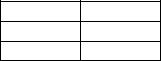
The NC has a memory to store machining programs. The memory capacity is selected depending on the size of the user program. On execution of a program, the program is transferred from the memory to the operation buffer (RAM).
If the program size is larger than the operation buffer capacity, (for example, if the program size is larger than 320 m (1050 ft.) although the operation buffer capacity is 320 m (1050 ft.)), the program cannot be transferred from the memory to the operation buffer in batch (at one time). Depending on the size of a program in comparison to the operation buffer capacity, two types of operation methods are available (operation method A and operation method B), and restrictions apply in programming according to the operation method used.
Machining program |
Memory |
Operation buffer |
(RAM) |
Program selection |
Operation |
ME33018R1000300130001

5228-E P-11
SECTION 1 PROGRAM CONFIGURATIONS
(2)Operation Methods
Select the operation method using the pop-up window MAIN PROGRAM SELECT (MEMORY MODE) that appears when calling a program to be run. The operation method can be also selected by the setting at the NC optional parameter (word) No. 11.
ME33018R1000300130002
•When A-Mtd is selected
Program running method A becomes effective.
The program to be executed is transferred to the operation buffer in batch.
This method is used when the program is smaller than the operation buffer capacity.
•When B-Mtd is selected
Program running method B becomes effective.
The program to be executed is called to the operation buffer in several segments. This method is used when the program is larger than the operation buffer capacity.
Since schedule programs, subprograms, and library programs are generally called to the operation buffer in batch, these programs must be created with restriction placed on their capacities.
•When S-Mtd is selected
Program running method S becomes effective.
This method is used to execute a large program which does not use branch or subprogram call functions.

5228-E P-12
SECTION 1 PROGRAM CONFIGURATIONS
•When selecting an operation method, also select the program size and whether the program has a sub program branch or not (only in the case of operation A and B). The table below shows the relation between the operation method and the program size.
Item |
Program of normal |
Large program |
||||
size |
||||||
|
|
|
|
|
||
|
|
|
|
|||
Program running method |
Method A |
Method B |
Method S |
|||
|
|
|
|
|
|
|
|
|
Main program |
|
2GB |
|
|
|
|
|
|
|
|
|
|
|
Sub program |
|
|
- |
|
Program size |
|
|
Total program size is |
|
|
|
|
Library |
Total program size is |
|
|||
limit |
|
program |
2MB. |
Total program size is |
||
|
about 1.8 MB. |
|||||
|
|
|
|
about 1.8 MB. |
||
|
|
Schedule |
|
|||
|
|
|
|
|||
|
|
program |
|
|
|
|
|
|
|
|
|
||
Sub program |
function |
Usable |
Usable |
Unusable (alarm) |
||
|
|
|
|
|
||
Branch function |
|
Usable |
Usable |
Unusable (alarm) |
||
|
|
|
|
|
|
|
Destination of |
|
Main program |
|
|
|
|
|
|
|
|
|
||
|
Sub program |
|
|
|
||
a jump |
|
|
Sequence label or |
Sequence label or |
|
|
|
Library |
- |
||||
specified in |
|
|||||
|
program |
sequence number |
sequence number |
|||
branch |
|
|
||||
|
|
|
|
|
||
command |
|
Schedule |
|
|
|
|
|
|
program |
|
|
|
|
Main program |
sequence label |
Unlimited |
Unlimited |
Unlimited |
||
limit |
|
|||||
|
|
|
|
|||
|
|
|
|
|||
Program selection time |
*1 |
*1 |
Completed immediately |
|||
|
|
|
|
|
|
|
*1. Time varies with the selected program size.
(3)Programming Restrictions for the Operation Method
For details of restrictions that must be taken into consideration when writing a program, refer to SECTION 12, “PSELECT BLOCK”.
(4)Others
•The maximum capacity for running the main program is about 2 GB when the operation method B is selected.
•The library program capacity is equivalent to the designated library program buffer size. This means that the library program buffer size is always contained in the operation capacity even if a library program is not registered.
•The number of subprograms and library programs stored in memory is independent of the operation buffer size. They are always 126 and 65, respectively.

5228-E P-13
SECTION 2 COORDINATE SYSTEMS AND COORDINATE COMMANDS
SECTION 2 COORDINATE SYSTEMS AND COORDINATE COMMANDS
1.Coordinate System
1-1. Coordinate Systems and Values
In order to move a cutting tool to a target position, a coordinate system must be established to specify the target position using coordinate values in the coordinate system.
The OSP-P200M uses three types of coordinate system (machine coordinate system, work coordinate system, and local coordinate system). These coordinate systems are briefly explained below.
•Machine coordinate system
The machine coordinate system is set by the machine tool manufactures. Although the setting may be changed by the user, machine dependent setting values such as pitch error compensation data and travel limit values must be changed accordingly.
•Work coordinate system
A work coordinate system is set by the user.
•Local coordinate system
A local coordinate system set temporarily by the commands in a program.
The user can select the coordinate system to be used as needed from the coordinate systems indicated above.
The coordinate value is represented by components of the axes which make up the coordinate system. Usually, a maximum of six axis components is used (the number differs depending on the NC unit specifications.)
Example:
X__Y__Z__W__A__C__
ME33018R1000400010001
The number of programmable axes, that is, the number of axis components used to define a coordinate value varies depending on the machine specifications. This manual, therefore, uses the following designation to indicate a coordinate value.
IP__
1-2. Machine Zero and Machine Coordinate System
The reference point specific to the individual machine is referred to as the machine zero and the coordinate system having the machine zero as the origin is referred to as the machine coordinate system.
The machine zero is set for each individual machine using system parameters.
Since the travel end limits and the home positions are set in the machine coordinate system, the user should not change the location of the machine zero at his/her own discretion.
A cutting tool may not always be moved to the machine zero.
5228-E P-14
SECTION 2 COORDINATE SYSTEMS AND COORDINATE COMMANDS
1-3. Work Coordinate System
The coordinate system used to machine workpieces is referred to as the work coordinate system.
•Work coordinate systems are established and stored with work coordinate system numbers in the memory before starting operation. The desired work coordinate system may be called at the start of machining.
•Work coordinate systems are set by specifying the distance from the machine zero to the origin of a work coordinate system as an offset value (work zero offset).
•For details, see SECTION 4, “Selection of Work Coordinate System” and SECTION 4, “Change of Work Coordinate System”.
1-4. Local Coordinate System
Programming the entire operation of a workpiece using only a work coordinate system may sometimes be difficult on some portions of the workpiece. In such cases, programming is facilitated by setting a new coordinate system appropriate for a specific workpiece portion.
The new coordinate system is referred to as a local coordinate system.
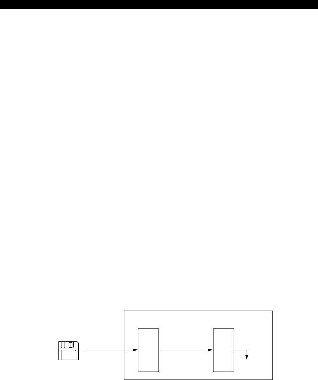
•The desired local coordinate system can be established by specifying the origin in reference to the origin of the presently selected work coordinate system and the angle of rotation on the specified plane about the origin of the local coordinate system to be set with G11. Once a local coordinate system has been established, all coordinate values are executed in the newly set local coordinate system.
To change the local coordinate system to another one, the position of the origin of the new local coordinate system and the angle of rotation about the origin should be specified with G11.
As explained above, a local coordinate system can be established only by specifying the coordinate values of the origin and the angle of rotation in a program.
•To designate coordinate values in the work coordinate system, cancel the local coordinate system by specifying G10.
•For details, refer to SECTION 4, “Parallel Shift and Rotation of Coordinates System”.
Coordinate system parallel shift amount (Specified in a program)
Work zero offset amount |
Rotating angle of local coordinate system |
(Set by zero point data) |
|
|
Local coordinate system zero point |
Machine zero offset amount
(Set by system parameter)
Work coordinate system zero point
Machine zero
Zero point for position encoder
ME33018R1000400040001

5228-E P-15
SECTION 2 COORDINATE SYSTEMS AND COORDINATE COMMANDS
2.Coordinate Commands
2-1. Numerically Controlled Axes
• The following table lists the addresses to be specified to control the axes.
|
Address |
Contents |
|
Basic axis |
X, Y, Z |
Addresses corresponding to the three axes |
|
orthogonal to one another |
|||
|
|
||
|
|
|
|
Parallel axis |
U, V, W |
Addresses of three orthogonal axes parallel |
|
to the basic axes |
|||
|
|
||
|
|
|
|
Rotary axis |
A, B, C |
Addresses of rotary axis in a plane right |
|
angle to the basic axis |
|||
|
|
||
|
|
|
|
Circular |
|
Addresses specifying distances, parallel to |
|
l, J, K |
an individual axis, from a start point to the |
||
interpolation |
|||
|
center of an arc |
||
parameters |
|
||
|
|
||
R |
Addresses specifying the radius of an arc |
||
|
|||
|
|
|
•An axis movement command consists of an axis address, a sign indicating the direction of the axis movement, and a numeric value which describes the axis movement. Refer to “Absolute and Incremental Commands” for the designation of numeric values.
•In this manual, to simplify the explanation for axis designation, “Xp”, “Yp”, and “Zp” are used instead of the actual axis addresses. They represent the axis as follows:
Xp X-axis and the axis parallel to X-axis (U-axis) Yp Y-axis and the axis parallel to Y-axis (V-axis) Zp Z-axis and the axis parallel to Z-axis (W-axis)
•The maximum number of controllable axes is six. This capability varies depending on the NC model.
•The following table shows the number of simultaneously controllable axes in each of the axis movement modes.
|
Number of Simultaneously Controllable Axes |
|
(“n” represents the number of controllable axes.) |
|
|
Positioning |
n |
|
|
Linear interpolation |
n |
|
|
Circular interpolation |
2 |
|
|
Helical cutting |
3 |
|
|
Manual operation |
1 |
|
|
Pulse handle operation |
1 |
|
|
In pulse handle operation, the optional 3-axis control function is available.

5228-E P-16
SECTION 2 COORDINATE SYSTEMS AND COORDINATE COMMANDS
• The positive directions of the linear and rotary axes are defined as follows:
ME33018R1000400050001
The definition of the coordinate axes and directions conforms to ISO R841.
ISO: International Organization of Standardization
2-2. Unit Systems
The unit systems that can be used in a program are described below. Note that the unit system selected for programming and the unit system used for setting data such as zero point, tool data, and parameters are independent of each other. The unit systems to be used for inputting the data are set at NC optional parameter (INPUT UNIT SYSTEM).
2-2-1. Minimum Input Unit
The minimum input unit is the smallest unit of a value that may be entered in a program. For a linear axis, the minimum input unit is 0.001 mm or 0.0001 inch.
For the NC with metric / inch switchable specification, the unit system can be selected by the setting at LENGTH UNIT SYSTEM of NC optional parameter (INPUT UNIT SYSTEM).
For a rotary axis, the minimum input unit is 0.001 degree or 0.0001 degree. Either 0.001 degree or 0.0001 degree can be selected by the setting at ANGLE of NC optional parameter (INPUT UNIT SYSTEM).
2-2-2. Basic Input Unit
The input unit may be changed to parameter (INPUT UNIT SYSTEM). second.
the “basic” unit by the setting at LENGTH of NC optional The fundamental units are then 1 mm, 1 inch, 1 degree, and 1
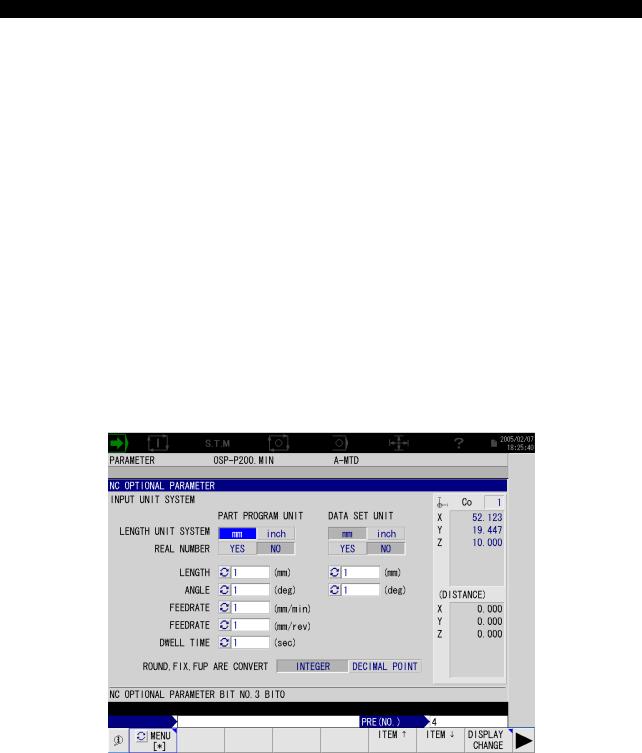
5228-E P-17
SECTION 2 COORDINATE SYSTEMS AND COORDINATE COMMANDS
2-2-3. Numeric Values (inch / metric switchable as optional function)
As the unit for specifying program values, “mm”, “deg.”, “sec”, etc. are used. For these units, a decimal point may be used.
•Cautions on using a decimal point value
a.A decimal point value must not be used for addresses O, N, G, and M.
b.If a decimal point is not entered in a numeric value, the decimal point is assumed to exist at the end of the specified numeric value.
c.If a value is set below the specified minimum input unit, the data is processed in the following manner.
•For addresses S, T, H, D, Q, etc. that require integer type data, the value below the minimum input unit is truncated.
•For addresses that use real data, the value below the minimum input unit is rounded.
•The input unit of dimension commands is determined by the setting at NC optional parameter (INPUT UNIT SYSTEM) or NC optional parameter (bit) No. 3, bit 0 to bit 7 and No. 4, bit 0. How these bits set the input unit is shown below.
•NC optional parameter (INPUT UNIT SYSTEM) screen
ME33018R1000400090001
|
|
|
|
|
|
5228-E P-18 |
|
|
|
|
|
SECTION 2 COORDINATE SYSTEMS AND COORDINATE COMMANDS |
|
||
|
• |
NC optional parameter (bit) No. 3, bit 0 to bit 7 and No. 4, bit 0 |
|
|
|||
|
|
|
|
|
|
||
|
Parameter |
Bit |
Contents |
With |
Without |
||
|
No. |
|
No. |
Check Mark |
Check Mark |
||
|
|
|
|||||
|
|
|
0 |
Sets the unit system of length, “inch” or “mm”. |
inch |
mm |
|
|
|
|
(*2) |
||||
|
|
|
|
|
|
|
|
|
|
|
|
|
|
|
|
|
|
|
|
|
Unit of 1 mm, |
Conforms to the |
|
|
|
|
|
|
setting for bit 2 |
||
|
|
|
|
|
1 inch, 1 deg., |
||
|
|
|
1 |
Sets the unit of 1 mm, 1 inch, 1 deg., and 1 sec. |
to bit 5 and bit 7 |
||
|
|
|
|
|
and 1 sec is |
of No. 3 and bit |
|
|
|
|
|
|
selected. |
||
|
|
|
|
|
0 of No. 4. |
||
|
|
|
|
|
|
||
|
|
|
|
|
|
|
|
|
|
|
2 |
Sets unit of length, “0.01 mm” or “0.001 mm”. |
0.01 mm |
0.001 mm |
|
|
|
|
|
|
|
|
|
|
|
|
3 |
Sets the unit of feedrate, 0.1 mm/min, 0.01 |
0.1 mm/min |
1 mm/min |
|
|
3 |
|
inch/min, or 1 mm/min, 0.1 inch/min |
0.01 inch/min |
0.1 inch/min |
||
|
|
|
|||||
|
|
|
4 |
Sets the unit of feedrate, 0.001 mm/rev, 0.0001 |
0.001 mm/rev |
0.01 mm/rev |
|
|
|
|
inch/rev, or 0.01 mm/rev, 0.001 inch/rev |
0.0001 inch/rev |
0.001 inch/rev |
||
|
|
|
|
||||
|
|
|
|
|
|
|
|
|
|
|
5 |
Sets the unit of time, “0.01 sec” or “0.1 sec”. |
0.01 sec |
0.1 sec |
|
|
|
|
|
|
|
|
|
|
|
|
|
Sets the unit place at “1 mm”, “1 inch”, “1 deg”, |
Unit place is set |
Conforms to the |
|
|
|
|
|
at “1 mm”, |
setting for bit 1 |
||
|
|
|
6 |
and “1 sec” when decimal point input is |
“1 inch”, |
||
|
|
|
to bit 5, and bit |
||||
|
|
|
|
selected. |
“1 deg”, and |
||
|
|
|
|
7. |
|
||
|
|
|
|
|
“1 sec”. |
|
|
|
|
|
|
|
|
|
|
|
|
|
|
|
|
|
|
|
|
|
7 |
Sets the unit time, “0.001 sec” or “0.1 sec”.(*1) |
0.001 sec |
0.1 sec |
|
|
|
|
|
|
|
|
|
|
4 |
|
0 |
Sets the unit of angle, “0.001 deg” or “0.0001 |
0.0001 deg |
0.001 deg |
|
|
|
deg”. |
|||||
|
|
|
|
|
|
|
|
|
|
|
|
|
|
|
|
*1: |
The unit of time is always “0.01 sec” if “1” is set for bit 5. |
|
|
||||
*2: |
The setting for bit 0 is valid only when the inch/mm switchable specification is selected. |
||||||
Loading...