


 Loading...
CNC SYSTEM
OSP-P300S/P300L
ALARM & ERROR LIST
(1st Edition)
Pub No. 5921-E (LE37-006-R1) Nov. 2011

5921-E P-(i)
SAFETY PRECAUTIONS
SAFETY PRECAUTIONS
The machine is equipped with safety devices which serve to protect personnel and the machine itself from hazards arising from unforeseen accidents. However, operators must not rely exclusively on these safety devices: they must also become fully familiar with the safety guidelines presented below to ensure accidentfree operation.
This instruction manual and the warning signs attached to the machine cover only those hazards which Okuma can predict. Be aware that they do not cover all possible hazards.
1.Precautions Relating to Installation
(1)Please be noted about a primary power supply as follows.
Do not draw the primary power supply from a distribution panel that also supplies a major noise source (for example, an electric welder or electric discharge machine) since this could cause malfunction of the CNC unit.
If possible, connect the machine to a ground not used by any other equipment. If there is no choice but to use a common ground, the other equipment must not generate a large amount of noise (such as an electric welder or electric discharge machine).
(2)Installation Environment
Observe the following points when installing the control enclosure.
Make sure that the CNC unit will not be subject to direct sunlight.
Make sure that the control enclosure will not be splashed with chips, water, or oil.
Make sure that the control enclosure and operation panel are not subject to excessive vibrations or shock.
The permissible ambient temperature range for the control enclosure is 5 to 40°C (41 to 104°F).
The permissible ambient humidity range for the control enclosure is relative humidity 50% or less at 40°C (104°F) (no condensation).
The maximum altitude at which the control enclosure can be used is 1000 m (3281ft.).
2.Points to Check before Turning on the Power
(1)Close all the doors of the control enclosure and operation panel to prevent the entry of water, chips, and dust.
(2)Make absolutely sure that there is nobody near the moving parts of the machine, and that there are no obstacles around the machine, before starting machine operation.
(3)When turning on the power, turn on the main power disconnect switch first, then the CONTROL ON switch on the operation panel.

5921-E P-(ii)
SAFETY PRECAUTIONS
3.Precautions Relating to Manual/Continuous Operation
(1)Follow the instruction manual during operation.
(2)Do not operate the machine with the front cover, chuck cover, or another protective cover removed.
(3)Close the front cover before starting the machine.
(4)When machining the initial workpiece, check for machine operations, run the machine under no load to check for interference among components, cut the workpiece in the single block mode, and then start continuous operation.
(5)Ensure your safety before rotating the spindle or moving a machine part.
(6)Do not touch chips or workpiece while the spindle is rotating.
(7)Do not stop a rotating part with hand or another means.
(8)Check that the condition of hydraulic chuck jaws as mounted, operating pressure, and maximum permissible revolving speed.
(9)Check the condition and location of the cutting tool as mounted.
(10)Check the tool offset value.
(11)Check the zero offset value.
(12)Check that the SPINDLE OVERRIDE and FEEDRATE OVERRIDE dials on the NC operation panel are set to 100%.
(13)When moving the turret, check the software limits for X- and Z-axes or the locations of limit switch dogs to prevent interference with the chuck and tailstock.
(14)Check the location of the turret.
(15)Check the location of the tailstock.
(16)Cut workpieces with a transmitted power and torque within the permissible range.
(17)Chuck each workpiece firmly.
(18)Check that the coolant nozzle is properly located.
4.On Finishing Work
(1)On finishing work, clean the vicinity of the machine.
(2)Return the ATC, APC and other equipment to the predetermined retraction position.
(3)Always turn off the power to the machine before leaving it.
(4)To turn off the power, turn off the CONTROL ON switch on the operation panel first, then the main power disconnect switch.

5921-E P-(iii)
SAFETY PRECAUTIONS
5.Precautions during Maintenance Inspection and When Trouble Occurs
In order to prevent unforeseen accidents, damage to the machine, etc., it is essential to observe the following points when performing maitenance inspections or during checking when trouble has occurred.
(1)When trouble occurs, press the emergency stop button on the operation panel to stop the machine.
(2)Consult the person responsible for maintenance to determine what corrective measures need to be taken.
(3)If two or more persons must work together, establish signals so that they can communicate to confirm safety before proceeding to each new step.
(4)Use only the specified replacement parts and fuses.
(5)Always turn the power off before starting inspection or changing parts.
(6)When parts are removed during inspection or repair work, always replace them as they were and secure them properly with their screws, etc.
(7)When carrying out inspections in which measuring instruments are used - for example voltage checks - make sure the instrument is properly calibrated.
(8)Do not keep combustible materials or metals inside the control enclosure or terminal box.
(9)Check that cables and wires are free of damage: damaged cables and wires will cause current leakage and electric shocks.
(10)Maintenance inside the Control Enclosure
a.Switch the main power disconnect switch OFF before opening the control enclosure door.
b.Even when the main power disconnect switch is OFF, there may some residual charge in the MCS drive unit (servo/spindle), and for this reason only service personnel are permitted to perform any work on this unit. Even then, they must observe the following precautions.
MCS drive unit (servo/spindle)
The residual voltage discharges two minutes after the main switch is turned OFF.
c.The control enclosure contains the NC unit, and the NC unit has a printed circuit board whose memory stores the machining programs, parameters, etc. In order to ensure that the contents of this memory will be retained even when the power is switched off, the memory is supplied with power by a battery. Depending on how the printed circuit boards are handled, the contents of the memory may be destroyed and for this reason only service personnel should handle these boards.

5921-E P-(iv)
SAFETY PRECAUTIONS
(11)Periodic Inspection of the Control Enclosure
a.Cleaning the cooling unit
The cooling unit in the door of the control enclosure serves to prevent excessive temperature rise inside the control enclosure and increase the reliability of the NC unit. Inspect the following points every three months.
Is the fan motor inside the cooling unit working?
The motor is normal if there is a strong draft from the unit.
Is the external air inlet blocked?
If it is blocked, clean it with compressed air.
6.General Precautions
(1)Keep the vicinity of the machine clean and tidy.
(2)Wear appropriate clothing while working, and follow the instructions of someone with sufficient training.
(3)Make sure that your clothes and hair cannot become entangled in the machine. Machine operators must wear safety equipment such as safety shoes and goggles.
(4)Machine operators must read the instruction manual carefully and make sure of the correct procedure before operating the machine.
(5)Memorize the position of the emergency stop button so that you can press it immediately at any time and from any position.
(6)Do not access the inside of the control panel, transformer, motor, etc., since they contain highvoltage terminals and other components which are extremely dangerous.
(7)If two or more persons must work together, establish signals so that they can communicate to confirm safety before proceeding to each new step.
5921-E P-(v)
SAFETY PRECAUTIONS
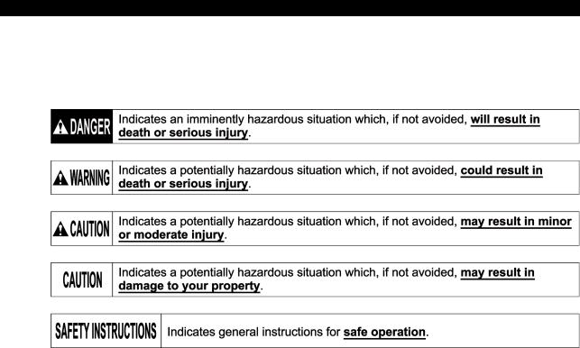
7.Symbols Used in This Manual
The following warning indications are used in this manual to draw attention to information of particular importance. Read the instructions marked with these symbols carefully and follow them.

5921-E P-(i)
INTRODUCTION
INTRODUCTION
Before using this NC unit, read this manual thoroughly in order to ensure correct use.
This manual explains how to use and maintain the control so that it will deliver its full performance and maintain accuracy over the long term.
You must pay particular attention to the cautions given in this manual; read them carefully and make sure you fully understand them before operating the NC.
|
|
|
5921-E P-(i) |
|
|
|
TABLE OF CONTENTS |
|
|
TABLE OF CONTENTS |
|
SECTION 1 CLASSIFICATION OF ALARMS ........................................................... |
1 |
||
1-1. |
Alarm Classifications ......................................................................................................... |
1 |
|
1-2. |
Object Number and Object Message ................................................................................ |
2 |
|
|
1-2-1. |
Alarm Codes........................................................................................................ |
3 |
|
1-2-2. |
Bit conversion method......................................................................................... |
3 |
|
1-2-3. |
How to check alarm contents .............................................................................. |
4 |
SECTION 2 |
ALARM P............................................................................................... |
5 |
SECTION 3 |
ALARM A............................................................................................. |
74 |
SECTION 4 |
ALARM B........................................................................................... |
249 |
SECTION 5 |
ALARM C........................................................................................... |
464 |
SECTION 6 |
ALARM D........................................................................................... |
544 |
SECTION 7 |
ERROR.............................................................................................. |
645 |
SECTION 8 |
APPENDIX ........................................................................................ |
754 |
8-1. Factor Classification Code/Factor Parameter................................................................ |
754 |
|
8-1-1. Factor Classification Code/Factor Parameter (for Machine) ........................... |
754 |
|

5921-E P-1
SECTION 1 CLASSIFICATION OF ALARMS
SECTION 1 CLASSIFICATION OF ALARMS
Alarms related with the OSP are classified into five types such as Alarm P, A, B, C and D.
1-1. Alarm Classifications
|
Alarm |
Machine Conditions When ALARM Lamp |
Operative NC Functions Thereafter |
|
|
Comes ON |
|||
|
|
|
||
P |
|
Stops NC operation. |
|
All NC functions are inoperative. |
|
|
|
|
Concerning the control, cancel the alarm |
|
|
|
axis feed |
|
|
|
|
|
by turning power on again after turning it |
|
|
Stops; |
spindle rotation |
|
|
|
off once. |
||
|
|
|
|
|
|
|
|
coolant supply |
|
|
|
|
|
|
|
|
|
|
|
|
|
Shuts off power supply |
to X- and Z-axis |
|
|
|
servo drives. |
|
|
|
|
|
|
|
|
|
Alarm display is displayed on the operation |
|
|
|
|
panel. |
|
|
|
|
|
|
|
A |
|
|
axis feed |
Operations for display are possible. |
|
|
Stops; |
|
The machine remains inoperative until |
|
|
spindle rotation |
||
|
|
|
|
the control is reset and the alarm |
|
|
|
coolant supply |
|
|
|
|
canceled. |
|
|
|
|
|
|
|
|
Shuts off power supply to X- and Z-axis |
||
|
|
|
||
|
|
servo drives. |
|
|
|
|
|
|
|
|
|
Alarm display is given on the operation |
|
|
|
|
panel. |
|
|
|
|
|
|
|
B |
|
The commands in the active block are |
Operations for display are possible. |
|
|
|
completed. |
|
The machine remains inoperative until |
|
|
|
the control is reset and the alarm |
|
|
|
Spindle rotation and coolant supply do not |
||
|
|
stop. |
|
canceled. |
|
|
|
|
|
|
|
Power supply to X- and Z-axis servo drives |
|
|
|
|
is not shut off. |
|
|
|
|
|
|
|
|
|
Alarm display is given on the operation |
|
|
|
|
panel. |
|
|
|
|
|
|
|
C |
|
The part program being run is executed to |
Operations for display are possible. |
|
|
|
the end (up to M02 command). |
No new program can be run until the |
|
|
|
|
control is reset and the alarm is |
|
|
|
Spindle rotation and coolant supply do not |
||
|
|
stop. |
|
canceled. |
|
|
|
|
|
|
|
Power supply to X- and Z-axis servo drives |
|
|
|
|
is not shut off. |
|
|
|
|
|
|
|
|
|
Alarm display is given on the operation |
|
|
|
|
panel. |
|
|
|
|
|
|
|
D |
|
This alarm does not have any influence on |
Operations on the operation panel are all |
|
|
|
the machine operation. |
|
operative. Alarm cannot be canceled |
|
|
Alarm display is given on the operation |
unless the cause of the alarm is |
|
|
|
panel. |
|
removed. |
|
|
|
|
|

5921-E P-2
SECTION 1 CLASSIFICATION OF ALARMS
Display Format of Alarm P, A, B, C and D
ALARM-A
Alarm number
Object number
Alarm level
Alarm message
Object message
Alarm code
Alarm character-string
LE37006R0100300020001
1-2. Object Number and Object Message
The object number and the object message show the programming system and the control axis where the alarm has occurred by the number and message as shown in the table blow:
Object No. |
|
Meaning |
Object message |
Notes |
None |
No classification |
None |
|
|
01 |
System 1 |
“A side” or “1-A sd” |
1st spindle and turret A |
|
02 |
System 2 |
“B side” or “1-B sd” |
1st spindle and turret B |
|
03 |
System 3 |
“2-A sd” |
2d spindle and turret A |
|
04 |
System 4 |
“2-B sd” |
2d spindle and turret B |
|
11 |
1st X-axis |
“XAaxis” or “X-axis” |
|
|
12 |
1st Y-axis |
“YAaxis” or “Y-axis” |
|
|
13 |
1st Z-axis |
“ZAaxis” or “Z-axis” |
|
|
16 |
1st W-axis |
“W-axis” |
|
|
19 |
1st C-axis |
“C-axis” or “Caxis1” |
|
|
20 |
1st S-axis |
“SPDL” or “SPDL-1” |
|
|
21 |
1st T-axis |
“TAaxis” or “T-axis” |
|
|
22 |
1st M-axis |
“MAaxis” or “M-axis” |
|
|
31 |
2d |
X-axis |
“XBaxis” |
|
32 |
2d |
Y-axis |
“YBaxis” |
|
33 |
2d |
Z-axis |
“ZBaxis” |
|
39 |
2d |
C-axis |
“Caxis2” |
|
40 |
2d |
S-axis |
“SPDL-2” |
Sub spindle, pick-off spindle |
41 |
2d |
T-axis |
“TBaxis” |
|
42 |
2d |
M-axis |
“MBaxis” |
|
53 |
3d |
Z-axis |
“ZCaxis” |
LT series |
As indicated above, the object numbers and messages to be used are determined by the machine specifications.
5921-E P-3
SECTION 1 CLASSIFICATION OF ALARMS
1-2-1. Alarm Codes
In this manual, alarm codes are explained using such as "X", "XX", and "XXYY".
Explanation is given in the following methods:
(1)The alarm code indicated in this text can be used directly as the key to find the contents of error.
(2)The alarm code indicated in this text should first be converted into bit expression (pattern), which is then used as the key to find the contents of error.
In the case of 2), the procedure to convert the alarm code into bit pattern is shown below.
1-2-2. Bit conversion method
Alarm Code |
|
|
|
|
Alarm Code |
|
|
|
|
(Expressed in |
|
Bit Pattern |
|
(Expressed in |
|
Bit Pattern |
|
||
hexadecimal) |
|
|
|
|
hexadecimal) |
|
|
|
|
0 |
0 |
0 |
0 |
0 |
8 |
1 |
0 |
0 |
0 |
1 |
0 |
0 |
0 |
1 |
9 |
1 |
0 |
0 |
1 |
2 |
0 |
0 |
1 |
0 |
A |
1 |
0 |
1 |
0 |
3 |
0 |
0 |
1 |
1 |
B |
1 |
0 |
1 |
1 |
4 |
0 |
1 |
0 |
0 |
C |
1 |
1 |
0 |
0 |
5 |
0 |
1 |
0 |
1 |
D |
1 |
1 |
0 |
1 |
6 |
0 |
1 |
1 |
0 |
E |
1 |
1 |
1 |
0 |
7 |
0 |
1 |
1 |
1 |
F |
1 |
1 |
1 |
1 |
5921-E P-4
SECTION 1 CLASSIFICATION OF ALARMS
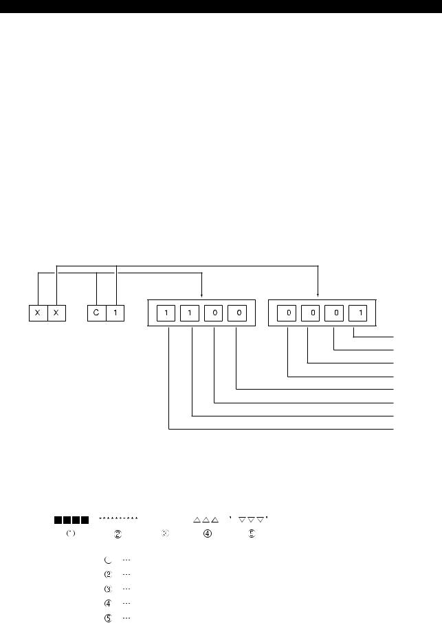
1-2-3. How to check alarm contents
The method to find the details of the alarm indicated by the bit pattern is explained below using an example.
Example:
[Code] XX
XX bit0->Battery error
bit1->EC I/O power shut off error
bit2->ECC error
bit3->Not used
bit4->Not used
bit5->EDRQ INT signal
bit6->ECP INT signal
bit7->ECP RUN signal
If an alarm occurs, a hexadecimal number is displayed.
If "$C1" is displayed, for example, first convert this "$C1" into bits.
bit 0 bit 1 bit 2 bit 3 bit 4 bit 5 bit 6 bit 7
After the conversion, it is known that Bit0, Bit6, and Bit7 are ON. See the information above and you will find that these error codes
correspond to "battery error", "ECP INT signal", and "ECP RUN signal", respectively.
Error Display Format
ERROR
Error number
Error message
Indication of ERROR
Error code
Error character-string
LE37006R0100300060001
5921-E P-5
|
|
|
SECTION 2 ALARM P |
SECTION 2 |
ALARM P |
|
|
0700 |
NC start-up error ........................................................................................... |
10 |
|
0701 |
P100-Menu initialization failure ..................................................................... |
10 |
|
0702 |
Power failure upon start-up ........................................................................... |
11 |
|
0703 |
Load information file not found ..................................................................... |
11 |
|
0704 |
File load error ................................................................................................ |
11 |
|
0705 |
Default scheduling table error ....................................................................... |
12 |
|
0706 |
Backup data file error .................................................................................... |
12 |
|
0707 |
DTL link/unlink error ..................................................................................... |
12 |
|
0708 |
RT thread stack overflow .............................................................................. |
13 |
|
0709 |
Hardware exception ...................................................................................... |
13 |
|
0710 |
System call error ........................................................................................... |
13 |
|
0711 |
AlarmService library error ............................................................................. |
14 |
|
0712 |
AlarmService internal error (exception) ........................................................ |
14 |
|
0713 |
AlarmService error ........................................................................................ |
14 |
|
0714 |
Blue screen ................................................................................................... |
14 |
|
0715 |
P100-Menu error ........................................................................................... |
15 |
|
0716 |
Floating point exception ................................................................................ |
15 |
|
0717 |
PLC control error .......................................................................................... |
15 |
|
0718 |
Real time thread time over ............................................................................ |
15 |
|
0719 |
HXCP thread error ........................................................................................ |
15 |
|
0720 |
AlarmService internal error ........................................................................... |
16 |
|
0721 |
DeviceNet error ............................................................................................. |
16 |
|
0723 |
DeviceNet I/O data link file read ................................................................... |
17 |
|
0725 |
M code data file ............................................................................................ |
17 |
|
0726 |
Safety speed data error ................................................................................ |
17 |
|
0727 |
MCS firmware doesn't support POS2 unit .................................................... |
17 |
|
0728 |
FL-net error ................................................................................................... |
18 |
|
0729 |
Non-responsive software detected. .............................................................. |
18 |
|
0731 |
R Spec. error ................................................................................................ |
18 |
|
0732 |
Unable to execute lost motion compensation ............................................... |
18 |
|
0735 |
MCS DD encoder link error ........................................................................... |
18 |
|
0736 |
MCS DD encoder error ................................................................................. |
19 |
|
0737 |
MCS DD encoder (slave sensor) detected error ........................................... |
19 |
|
0738 |
MCS DD encoder initialization failure ........................................................... |
20 |
|
0739 |
MCS DD encoder (slave sensor) initialization failure .................................... |
21 |
|
0741 |
MCS firmware version error .......................................................................... |
22 |
|
0742 |
Relocation detection error ............................................................................. |
22 |
|
0744 |
MCS power supply unit overload .................................................................. |
22 |
|
5921-E P-6
|
|
SECTION 2 ALARM P |
0750 |
The spec.-code or select-soft. was wrong |
.................................................... 22 |
0752 |
VDU communication error ............................................................................ |
23 |
0753 |
VDU detected error ....................................................................................... |
23 |
0754 |
VDU initialization failure ................................................................................ |
24 |
0755 |
SIO link error ................................................................................................. |
24 |
0756 |
PSC optical scale encoder error ................................................................... |
25 |
0757 MF-SAFETY Error ........................................................................................ |
25 |
|
0758 |
Safety I/O Error ............................................................................................. |
26 |
0759 |
Safety Servo Link Error ................................................................................. |
28 |
0782 |
Magnetic encoder speed detection error ...................................................... |
29 |
0783 |
MCS Rotary encoder 5 initialization failure ................................................... |
29 |
0784 |
MCS Rotary encoder 5 error ......................................................................... |
30 |
0785 |
MCS Rotary encoder 4 initialization failure ................................................... |
30 |
0786 |
MCS Rotary encoder 4 error ......................................................................... |
30 |
0787 |
MCS Rotary encoder 3 initialization failure ................................................... |
30 |
0788 |
MCS Rotary encoder 3 error ......................................................................... |
30 |
0789 |
MCS Rotary encoder 2 error ......................................................................... |
31 |
0790 |
MCS Rotary encoder 1 initialization failure ................................................... |
31 |
0791 |
MCS Rotary encoder 1 error ......................................................................... |
31 |
0792 |
MCS Linear scale 4 initialization failure ........................................................ |
32 |
0793 |
MCS Linear scale 4 error .............................................................................. |
32 |
0794 |
MCS Linear scale 3 initialization failure ........................................................ |
32 |
0795 |
MCS Linear scale 3 error .............................................................................. |
33 |
0796 |
MCS Linear scale 2 initialization failure ........................................................ |
33 |
0797 |
MCS Linear scale 2 error .............................................................................. |
33 |
0798 |
MCS Linear scale 1 initialization failure ........................................................ |
33 |
0799 |
MCS Linear scale 1 error .............................................................................. |
33 |
0800 |
Spindle D/A control data file read ................................................................. |
34 |
0801 |
TCP/IP board detected error ......................................................................... |
34 |
0802 |
Load information file not found ..................................................................... |
35 |
0803 |
File load error ................................................................................................ |
35 |
0804 |
MSB file mismatch ........................................................................................ |
35 |
0805 |
MOP-Tool parameter PBU load .................................................................... |
35 |
0806 |
MOP-Tool tool data PBU load ...................................................................... |
35 |
0807 |
ACP panel status receipt error ...................................................................... |
36 |
0808 |
Speed change ratio failure ............................................................................ |
36 |
0810 |
NC I/O data file read ..................................................................................... |
36 |
0812 |
MCS initialization error .................................................................................. |
36 |
0813 |
MCS Communication error ........................................................................... |
38 |
0814 |
MCS data file corrupt .................................................................................... |
39 |
5921-E P-7
|
|
SECTION 2 ALARM P |
0815 |
PLC real-time task loop error ........................................................................ |
40 |
0816 |
PLC initialization error ................................................................................... |
40 |
0817 |
MCS error ..................................................................................................... |
41 |
0818 |
ADP initialization failure ................................................................................ |
41 |
0820 |
Machine data file read .................................................................................. |
41 |
0821 |
Spindle gear ratio .......................................................................................... |
42 |
0822 |
Wheel data file read ...................................................................................... |
42 |
0823 AXIS CONSTRUCTION DATA setting error ................................................. |
42 |
|
0824 |
Unit connection mistake ................................................................................ |
43 |
0825 AXIS CONSTRUCTION name not set .......................................................... |
43 |
|
0826 AXIS CONSTRUCTION DATA file read ....................................................... |
43 |
|
0827 |
Control axis not found ................................................................................... |
43 |
0828 |
Wire feed axis No. error ................................................................................ |
43 |
0833 |
MCS option program file not sent ................................................................. |
44 |
0834 |
MCS servo data error ................................................................................... |
44 |
0835 |
MCS communication error ............................................................................ |
44 |
0836 |
Program request illegal ................................................................................. |
45 |
0837 |
Loader spec. code data error ........................................................................ |
45 |
0838 |
Loader backup data file read error ................................................................ |
45 |
0839 |
Specification conditions failure ..................................................................... |
45 |
0840 |
SuperHi-NC specification mismatch ............................................................. |
46 |
0841 |
FCP4 board detected error ........................................................................... |
46 |
0842 |
Safety monitor spec. error ............................................................................ |
46 |
0845 |
Specification code setting failure .................................................................. |
46 |
0846 |
Thermal deviation comp. backup data file read ............................................ |
47 |
0847 |
DNC-DT preload task start error ................................................................... |
47 |
0848 |
PSCB error ................................................................................................... |
47 |
0849 |
Synchronous axis tandem control initialization failure .................................. |
47 |
0850 |
MCS Undefined alarm number ..................................................................... |
48 |
0851 |
MCS Inverter unit fault .................................................................................. |
48 |
0852 |
Mistake in data from MCS to NC .................................................................. |
49 |
0853 MCS CON APA deviation ............................................................................. |
50 |
|
0854 |
MCS Power supply unit error ........................................................................ |
50 |
0855 |
MCS Converter link error .............................................................................. |
51 |
0856 |
MCS DC-bus voltage alarm .......................................................................... |
51 |
0857 |
MCS Motor overcurrent ................................................................................ |
51 |
0858 |
MCS Power unit overheat ............................................................................. |
51 |
0859 |
MCS Power unit overload ............................................................................. |
52 |
0860 |
MCS Supply voltage flutter ........................................................................... |
52 |
0861 |
MCS Inverter capacity differs from spec. ...................................................... |
52 |
5921-E P-8
|
|
SECTION 2 ALARM P |
0862 |
MCS Winding change failure ........................................................................ |
52 |
0863 |
MCS Encoder link error ................................................................................ |
53 |
0864 |
MCS Encoder detected error ........................................................................ |
53 |
0865 |
MCS Encoder initialization failure ................................................................. |
54 |
0866 |
MCS Encoder with shaft detected error ........................................................ |
54 |
0867 |
MCS Encoder with shaft initialization failure ................................................. |
54 |
0868 MCS ABSO SCALE error ............................................................................. |
55 |
|
0869 |
MCS ABSO SCALE initialization failure ........................................................ |
55 |
0870 |
MCS Magnetic encoder alarm ...................................................................... |
55 |
0871 |
MCS Resolver alarm ..................................................................................... |
55 |
0872 |
MCS Pulse generator count over .................................................................. |
56 |
0873 |
MCS Motor overheat ..................................................................................... |
56 |
0874 |
MCS Servo link error .................................................................................... |
56 |
0875 |
MCS Servo link disconnection ...................................................................... |
57 |
0876 |
Mistake in data from NC to MCS .................................................................. |
57 |
0877 |
MCS Servo data error ................................................................................... |
57 |
0878 |
MCS Illegal command ................................................................................... |
58 |
0879 MCS CON speed over .................................................................................. |
58 |
|
0880 MCS Speed command over .......................................................................... |
59 |
|
0881 MCS DIFF over ............................................................................................. |
59 |
|
0882 MCS APA speed over ................................................................................... |
59 |
|
0883 |
MCS Full-closed APA error ........................................................................... |
59 |
0884 MCS Over speed .......................................................................................... |
60 |
|
0885 |
MCS Speed deviation over ........................................................................... |
60 |
0886 |
MCS Collision detected ................................................................................ |
60 |
0887 |
MCS Urgent-stop time over .......................................................................... |
61 |
0888 |
MCS Belt is broken ....................................................................................... |
61 |
0889 |
MCS Axis change control error ..................................................................... |
61 |
0890 |
MCS Independent encoder initialization failure ............................................ |
61 |
0891 |
MCS Calculated current position lies outside range ..................................... |
62 |
0892 |
MCS Motor overload ..................................................................................... |
62 |
0893 |
MCS Safety speed monitor E-Link error ....................................................... |
62 |
0894 |
MCS ABSO SCALE sub-slider detected error .............................................. |
62 |
0895 |
MCS Tandem control communication error .................................................. |
63 |
0896 |
MCS Full abso scale link error ...................................................................... |
63 |
0897 |
MCS Full abso scale error ............................................................................ |
64 |
0898 |
MCS Full abso scale initialization failure ...................................................... |
64 |
0899 |
MCS Axis stop signal error ........................................................................... |
65 |
0940 |
Time sharing task control .............................................................................. |
65 |
0941 |
Real-time task control ................................................................................... |
65 |
5921-E P-9
|
|
SECTION 2 ALARM P |
0942 |
Real-time task loop error .............................................................................. |
65 |
0943 |
Main processor name incorrect .................................................................... |
66 |
0944 |
Slave processor name incorrect ................................................................... |
66 |
0945 |
Memory board/battery life ............................................................................. |
66 |
0951 |
SMP error ..................................................................................................... |
66 |
0952 |
Not equipped with processor board .............................................................. |
67 |
0954 |
Peripheral processor start ............................................................................. |
67 |
0955 |
Spec. code: data file ..................................................................................... |
67 |
0956 |
Backup data file read .................................................................................... |
68 |
0957 |
Graphic backup data file read ....................................................................... |
68 |
0958 |
Pitch compensation data file read ................................................................. |
68 |
0965 |
Configuration file format error ....................................................................... |
69 |
0971 |
Cache data: Initialization error ...................................................................... |
69 |
0988 |
Cache data: Operation error ......................................................................... |
69 |
0989 |
CPU information table data incorrect ............................................................ |
69 |
0990 |
TASK generate error ..................................................................................... |
70 |
0991 |
TASK information table data incorrect .......................................................... |
70 |
0992 |
PLC backup data file read ............................................................................ |
70 |
0993 |
TCP/IP board illegal ...................................................................................... |
71 |
0994 |
TCP/IP configuration file ............................................................................... |
71 |
0995 |
Machine axis data file ................................................................................... |
71 |
0996 |
PLC axis data file .......................................................................................... |
71 |
0997 |
PLC monitor backup data file read ............................................................... |
72 |
0998 |
PLC sequence program load ........................................................................ |
72 |
0999 |
Synchronous tap data file read ..................................................................... |
73 |

5921-E P-10
SECTION 2 ALARM P
0700 NC start-up error
An error occurred when NC started up.
[Object] None
[Character-string] None
[Code]
0x10000000: NC Configuration read error 0x10003000: Spec code read error 0x20000000: ServoLink board initializing error 0x3XXX00YY: NC data file read error
XXX:
0x002: HD backup status file 0x004: Parameter data file 0x008: Machine data file 0x010: PLC backup data file 0x020: PLC-HMI data file 0x040: Alarm History data file 0x080: PLC AXIS data pbu file
0x100: POT TOOL data pbu file (M/C only) 0x200: MOP TOOL Tool data file (M/C only) 0x400: MOP TOOL Parameter file (M/C only) 0x800: Thermal deviation compensation data file
YY:
0x01: File read open error 0x02: File read error 0x03: Version check error 0x04: Check sum error
0x05: Double check sum error 0x06: Backupped Memory error 0x07: File write open error 0x08: File write error
0x40000000: Axis information initializing error -More than 8 axis
0x50000000: PLC data file read error -Read failed M code data file
0x60000000: I/O Initializing error -PLC variable backup file read error -I/O forced data file read error
0x70000000: ServoLink Initializing error 0x80000000: Operation buffer get error 0x90000000: PBU data file read error 0xA0000000: Shared memory size definition error 0xA1XXXXXX: AlarmService start error
XXXXXX: Error code of AlarmService library function 0xA2400002: Alarm History read error 0xA3000000: Thread monitor initializing error
0xA9000000: Initialization processing of the safety logic was not completed within 20 seconds 0xA9000001: Axis construction definition file open error
0xA9000002: Axis construction definition file read error 0xA9000003: Axis construction definition file mismatch 0xFFFFFFFF: Debug information file read error
0701 P100-Menu initialization failure
An error occurred in P100-Menu while system startup.
[Object] None
[Character-string] None
[Code]
1:NC Control file was not found.
2:PLC Control file was not found.
3:NC-HMI was not found

5921-E P-11
SECTION 2 ALARM P
4:3D real sim file was not found.
5:MacMan file was not found.
6:Version mismatch between P100-Menu and PLC Control
7:Version mismatch between P100-Menu and MacMan
8:Version mismatch between P100-Menu and NC Control
11:Conf-P100-menu read error
12:An error occurred at RTOS
13:An error occurred at UPS Service
21:NC Control start failure
22:Error in obtaining shared objects
23:PLC Control start failure
24:NC-HMI start failure
25:3D real sim start failure
26:MacMan start failure
101:Startup sequence 0x10 receive failure
200:Startup sequence 0x10 send failure
201:Startup sequence 0x20 receive failure
300:Startup sequence 0x20 send failure
301:Startup sequence 0x30 receive failure
400:Startup sequence 0x30 send failure
401:Startup sequence 0x60 receive failure
500:Startup sequence 0x60 send failure
501:Startup sequence 0x70 receive failure
600:Startup sequence 0x70 send failure
601:Startup sequence 0x7C receive failure
700:Startup sequence 0x7C send failure
701:AlarmService start failure
702:Activation sequence 0x80 receive failure
[Probable Faulty Locations]
1.Execution file name failure 2.Data file name failure 3.RTOS failure
4.UPS function failure 5.Software failure 6.Software Version failure
0702 Power failure upon start-up
[Object] None
[Character-string] None
[Code] None
[Probable Faulty Locations]
1.Power failure during while system startup 2.Power shutoff during while system startup
0703 Load information file not found
A load information file was not found.
[Object] None
[Character-string] None
[Code] None
0704 File load error
An object file was not loaded correctly.
[Object] None
[Character-string]

5921-E P-12
SECTION 2 ALARM P
None
[Code]
1:A file was not found
2:The attribute of file was not correct.
3:The load address information of file was not correct 4:An error occurred when file was loaded
FFFFFFFF:The details of alarm was displayed by message from OS
0705 Default scheduling table error
A default scheduling table error was detected.
[Object] None
[Character-string] None
[Code]
0x00010001: RTIN default scheduling table error (element number) 0x00010002: RTIN default scheduling table error (end element) 0x00020001: TSMN default scheduling table error (element number) 0x00020002: TSMN default scheduling table error (initial attribute)
[Probable Faulty Locations] 1.NC software failure
0706 Backup data file error
Error occurred when load/save the backup file.
[Object] None
[Character-string] None
[Code] XXXXYYYY
XXXX
0x0002:HD backup status file 0x0004:Low speed NC backup data file 0x0008:High speed NC backup data file 0x0010:PLC backup data file 0x0020:PLC-HMI data file 0x0040:Alarm history data file 0x0080:PLC axis data file
0x0100:POT TOOL data file
0x0200:MOP TOOL Tool data file (M/C only) 0x0400:MOP TOOL Parameter data file (M/C only) 0x0800:Thermal deviation compensation data file
YYYY
1:File read open error 2:File read error 3:Version check error 4:Check sum error 5:Double check sum error
6:Backup memory check error 7:File write open error
8:File write error
0707 DTL link/unlink error
An error occurred in DTL link or unlink.
[Object] None
[Character-string] None
[Code]
1:RTIN refresh error
5921-E P-13
SECTION 2 ALARM P
2:TSMN refresh error
[Probable Faulty Locations]
1.Hardware failure 2.Software failure
0708 RT thread stack overflow
Stack overflow of RT thread was detected.
[Object] None
[Character-string]
Occurred RT thread name
[Code] None
[Probable Faulty Locations] 1.NC software failure
0709 Hardware exception
Hardware exception was occurred.
[Object] None
[Character-string]
Occurred RT thread name
[Code]
Hardware exception code 0x5555: CPU Diagnose error 0x8100:Divide by 0 error
0x8101:Unexpected Single Step Interrupt 0x8102:Unexpected NMI 0x8103:Unexpected Debug Interrupt 0x8104:Overflow error
0x8105:Array Bounds error 0x8106:Invalid Opcode error 0x8107:NPX Device not present 0x8108:Double Fault error 0x8109:Unknown Device error 0x810A:Invalid TSS error 0x810B:Segment not Present error 0x810C:Stack Fault error 0x810D:General Protection error 0x810E:Page Fault error 0x8110:Unknown Device error 1 0x8111:Alignment error
[Probable Faulty Locations] 1.Hardware failure 2.Software failure
[Note]
Alarm information is also displayed also in the console window.
0710 System call error
An error occurred in the INtime system call.
[Object] None
[Character-string]
Occurred RT thread name
[Code] XXXXYYYY
XXXX:INtime system call code
YYYY:Return value or status of INtime system call [Probable Faulty Locations]

5921-E P-14
SECTION 2 ALARM P
NC software failure
[Note]
Alarm information is also displayed also in the console window.
0711 AlarmService library error
An error occurred in the AlarmService library function.
[Object] None
[Character-string] Occurred thread name
[Code]
XXYYYYYY
XX:AlarmService library function code YYYYYY:AlarmService library function error code
[Probable Faulty Locations] NC software failure
[Note]
Alarm information is also displayed also in the console window.
0712 AlarmService internal error (exception)
An error occurred inside of AlarmService.
[Object] None
[Character-string] "ALMS"
[Code]
AlarmService internal error code
[Probable Faulty Locations] NC software failure
[Note]
Alarm information is also displayed also in the console window.
0713 AlarmService error
P100-Menu detected AlarmService error.
[Object] None
[Character-string] None
[Code] None
[Probable Faulty Locations] 1.NC software failure
0714 Blue screen
Blue screen (kernel stop error) occurred.
[Object] None
[Character-string] None
[Code] None
[Probable Faulty Locations] 1.Win32 application failure 2.Windows failure 3.Windows driver failure

5921-E P-15
SECTION 2 ALARM P
0715 P100-Menu error
An abnormal condition of P100-Menu was detected.
[Object] None
[Character-string] None
[Code] None
[Probable Faulty Locations] 1.P100-Menu failure
0716 Floating point exception
Floating point exception was occurred.
[Object] None
[Character-string]
Occurred RT thread name
[Code] XXXXYYZZ
XXXX:Exception code YY:Not used (0 fixed) ZZ:FPU status word
bit5:PE (Precision Exception Flag) bit4:UE (Underflow Exception Flag) bit3:OE (Overflow Exception Flag) bit2:ZE (Zero Divide Exception Flag)
bit1:DE (Denormalized Operand Exception Flag) bit0:IE (Invalid Operation Exception Flag)
[Probable Faulty Locations] NC software failure
0717 PLC control error
Error occurred on PLC Control.
[Object] None
[Character-string] None
[Code] XXXXYYYY
XXXX:PLC Control status YYYY:PLC Control error code
[Probable Faulty Locations] 1.PLC software failure
0718 Real time thread time over
Real time-type thread did not finish within the stated time
[Object] None
[Character-string]
RT thread name that was exceeded the stated time
[Code] None
[Probable Faulty Locations] 1.NC software failure
0719 HXCP thread error

5921-E P-16
SECTION 2 ALARM P
An abnormal condition of HXCP thread was detected.
[Object] None
[Character-string] None
[Code] None
[Probable Faulty Locations] 1.NC software failure
0720 AlarmService internal error
An error occurred inside of AlarmService.
[Object] None
[Character-string] "ALMS"
[Code]
AlarmService internal error code
[Probable Faulty Locations]
1.NC software failure 2.P100-Menu failure
0721 DeviceNet error
Error occurred on DeviceNet.
[Index] None
[Character-string] CH* SC$
* : Channel number where the error occurred. S : Sequence counter
[Code] XXYYZZZZ
XXSlave station MacID where the error occurred
YYSlave station
0x00 Normal or nonexistent slave station
0x46 Duplicate MacID error
0x48 Communication stop
0x49 Discrimination information was not compatible with scan list 0x4D Data size was not compatible with scan list
0x4E No response in the connection check.
0x4F Other slave stations are nonexistence on network 0x50 Idle condition
0x53 Error received in the connection check
0x54 Timeout occurred in the connection check
0x56 Turn into the idle mode 0x5B Bus off
0x5C Network power supply off
( XXXX became 0xFFFF,if its not caused by slave station, such as communication delay.) ZZZZ Scanner error status
bit 0 Memory check error bit 1 Scan list initialize error
bit 2 Scan list mismatch error(MacID) bit 3 Scan list mismatch error(Input data)
bit 4 Scan list mismatch error(Output data) bit 5 Duplicate MacID error
bit 6 Network power supply status error bit 7 Memory parity error
bit 8 Input data reception error(single) bit 9 Input data reception error(dowble)
bit10 Output data transmission error(single) bit11 Output data transmission error(dowble)

5921-E P-17
SECTION 2 ALARM P
bit12 Slave station communication delay error(single) bit13 Slave station communication delay error(dowble) bit14 Bus off
bit15 Diagnostic information access error
[Probable Faulty Locations]
1)Hardware failure 2)Software failure
0723 DeviceNet I/O data link file read
The NC failed to read DeviceNet IO data link file.
[Code]
I/O data file load status (in hexadecimal) 2 ->File open error (no file)
3 ->File read error (no data)
4 ->File attribute error (not "PBU1")
5 ->File close error
6 ->File size error (too small)
7 ->File size error (too large)
100->Wrong PLC machine type
200->Wrong PLC class
300->Wrong file version
1002 ->DN SCAN LIST CHANGE FILE OPEN ERROR
1003 ->DN SCAN LIST CHANGE FILE READ ERROR (NO DATA)
1004 ->DN SCAN LIST CHANGE FILE ATTRIBUTE ERROR (NO 'PBU1') 1005 ->DN SCAN LIST CHANGE FILE CLOSE ERROR
1006 ->DN SCAN LIST CHANGE FILE SIZE ERROR (SIZE SMALL)
0725 M code data file
Establishment data of reading M-code file is bad.
[Code]
1->The denial data is bad.
[Character string]
The number is M-code which is established bad data.
[Measures to Take]
Please correct the bad data of M-code.
0726 Safety speed data error
The safety speed data was in abnormal state in the machine without the CE marking safety speed monitor.
[Index]
Axis name or none (spindle)
[Character-string] None
[Code]
X
X=1:The guard number of the safety speed data was outside the range from -0 to 9.
[Measures to Take]
Change the safety speed monitor data file for axis control. Relevant specifications:Without CE mark safety speed monitor type
[Related Specifications]
Without CE mark safety speed monitor type
0727 MCS firmware doesn't support POS2 unit
This alarm occurs when the firmware ROM version of the NC axis/ machine(PLC) axis MIV unit is not 511 or later when the new POS unit is installed.
[Character-string] None
[Code] None

5921-E P-18
SECTION 2 ALARM P
0728 FL-net error
An error occurred during startup of the FL-net card.
[Object] None
[Character-string] None
[Code]
Y000XXX
Y:0
XXXX: 7F00:System error
7F01:Flash memory error 7F02:DRAM test error 7F03:NICE test error 7F04:EEPROM sum check error 7F05:CPU BUS error 7F06:illegal Instruction
Y:1
XXXX:
0004:Timeout error for 4 sec or longer Y:F
XXXX:
FFFF: FL-net card is not mounted
[Probable Faulty Locations] FL-net card is defective.
0729 Non-responsive software detected.
Non-answered software was detected.
[Object] None
[Character-string] None
[Code]
NT Process name
[Probable Faulty Locations] NC software failure
0731 R Spec. error
It is the illegal of "R SPEC".
[Index] None
[Code]
1:"NON R SPEC" of NC is OFF, and "R-SPEC" of SVDN-ID is OFF. 2:"NON R SPEC" of NC is ON, and "R-SPEC" of SVDN-ID is ON.
3:When there are 2 SVDN-boards in the machine, "R-SPEC" of one board is ON, other is OFF. 4X:"NON R SPEC" of NC is OFF, and "R-SPEC" of SVDN-ID is ON, and Restriction-Spec is ON.
0732 Unable to execute lost motion compensation
0735 MCS DD encoder link error
An error occurred in the encoder communication link.
[Object]
Axis name or none (spindle)
[Character-string] None
[Code] XXYYZZZZ

5921-E P-19
SECTION 2 ALARM P
XX= $FF (fixed)
YY= $00: Error is detected at the DD encoder.
$01: Error is detected at the DD encoder(slave sensor). ZZZZ = Encoder link error status at the time of error detection
bit15: Undefined bit14: Undefined
bit13: Error in communication with the DD encoder (slave sensor) bit12: Error in communication with the DD encoder
bit11: MT buffer error
bit10: Transmission loop error in AT mode
bit9 : Data over error in data receiving part of interface bit8 : Undefined
bit7 : Undefined
bit6 : Modulation code error bit5 : CRC error
bit4 : Format error
bit3 : Double transmission error bit2 : Double reception error bit1 : Parity error
bit0 : Time-out error
This alarm occurs only at ICB-H.
[Probable Faulty Locations]
DD encoder of DD encoder (slave sensor) of the pertinent axis Encoder link cables or connectors Inverter unit control board
0736 MCS DD encoder error
The DD encoder has become undetectable.
[Object]
Axis name or none (spindle)
[Character-string] None
[Code] XXYYZZZZ
XX= Positional data status bit7 : Error bit (1:error)
bit6 : Absolute position sensor margin error.(0:Normal, 1:Warning) bit5 : Gap-Warning (1:Gap-small,Toggle:Gap-big)
bit4 : Inclination-Warning (1:CCW-big, Toggle:CW-big) bit3 : Auto set mode (0:Normal, 1:Auto mode)
bit2 : Communication error (Toggle by detecting)
bit1,0: Error bit number of absolute position code.(It is indicated by 2bits.)
YY= Alarm code
01: Stop command has stopped. 02: Control parameter error
04: Absolutization error
05: Initialization speed too high 08: Auto-set-data error
0D: Speed too high
0E: Synchronization error
20:Absolutization mismatch (Only Format-5)
21:Communication-error of Master-sensor (Only Format-5) 3E: Code-error by Absolute-position-sensor
3F: Check-errotr by Absolute-position-code
40:Inclination-error (for plus)
41:Inclination-error (for minus)
42:Gap is narrow
43:Gap is wide
ZZZZ= 0000 fixed
This alarm occurs only at ICB-H.
[Probable Faulty Locations] DD encoder
0737 MCS DD encoder (slave sensor) detected error
The DD encoder (slave sensor) has become undetectable.

5921-E P-20
SECTION 2 ALARM P
[Object]
Axis name or none (spindle)
[Character-string] None
[Code] XXYYZZZZ
XX= Positional data status bit7 : Error bit (1:error)
bit6 : Absolute position sensor margin error.(0:Normal, 1:Warning) bit5 : Gap-Warning (1:Gap-small,Toggle:Gap-big)
bit4 : Inclination-Warning (1:CCW-big, Toggle:CW-big) bit3 : Auto set mode (0:Normal, 1:Auto mode)
bit2 : Communication error (Toggle by detecting)
bit1,0: Error bit number of absolute position code.(It is indicated by 2bits.)
YY= Alarm code
01: Stop command has stopped. 02: Control parameter error
04: Absolutization error
05: Initialization speed too high 08: Auto-set-data error
0D: Speed too high
0E: Synchronization error
20:Absolutization mismatch (Only Format-5)
21:Communication-error of Master-sensor (Only Format-5) 3E: Code-error by Absolute-position-sensor
3F: Check-errotr by Absolute-position-code
40:Inclination-error (for plus)
41:Inclination-error (for minus)
42:Gap is narrow
43:Gap is wide
ZZZZ= 0000 fixed
This alarm occurs only at ICB-H.
[Probable Faulty Locations] DD encoder (slave sensor)
0738 MCS DD encoder initialization failure
An error occurred in the initialization of the DD encoder.
[Object]
Axis name or none (spindle)
[Character-string] None
[Code] XXYYZZZZ
XX= Encoder link initialization sequence number (1B) at the time of the error detection
0:Reset
1:Network address setting
2:Request to send the basic information for communication
3:Change of communication software version
4:Acquisition of device information
5:Parameter change
6:Position detection start
7:AT mode start
YY= Error content (1B)
0:Communication error
1:Transmission start time over
2:Transmission finish time over
3:Reception finish time over
4:Abnormal response address
5:Abnormal response code
6:Parameter error
ZZZZ = Data (2B)
If YY = 0,
The encoder link error status C2ERR at the time of error detection appears.
If YY = 1, 2 or 3,

5921-E P-21
SECTION 2 ALARM P
The transmitted frame information QC2MTINF appears.
If YY = 4,
The network address of the responding device appears.
If YY = 5,
Alarm code + positional data status
Refer to MCS DD Encoder error (alarm 1136).
If YY = 6,
Parameter number at which the error is detected
1:Reception of insufficient number of parameters
2:Basic information for communication being incompatible
3:Multi-turn detection range over
4:Communication protocol version being incompatible
5:Positional data format being incompatible
6:Abbreviated data mode being incompatible
However, when abnormal voltage is detected at the encoder fuse XXYY = $FFFF fixed
ZZZZ = Detected voltage value of the encoder fuse (12[V] = $9980) Normal range: 10.6[V] to 13.8[V]
Allowable range: $8800 to $B000 This alarm occurs only at ICB-H.
[Probable Faulty Locations] DD encoder
Encoder link cables and connectors Inverter unit control board
0739 MCS DD encoder (slave sensor) initialization failure
An error occurred in the initialization of the DD encoder (slave sensor).
[Index]
Axis name or none (spindle)
[Character-string] None
[Code] XXYYZZZZ
XX= Encoder link initialization sequence number (1B) at the time of the error detection
0:Reset
1:Network address setting
2:Request to send the basic information for communication
3:Change of communication software version
4:Acquisition of device information
5:Parameter change
6:Position detection start
7:AT mode start
YY= Error content (1B)
0:Communication error
1:Transmission start time over
2:Transmission finish time over
3:Reception finish time over
4:Abnormal response address
5:Abnormal response code
6:Parameter error
ZZZZ = Data (2B)
If YY = 0,
The encoder link error status C2ERR at the time of error detection appears.
If YY = 1, 2 or 3,
The transmitted frame information QC2MTINF appears.
If YY = 4,
The network address of the responding device appears.
If YY = 5,
Alarm code + positional data status
Refer to MCS DD Encoder error (alarm 1136).
If YY = 6,
Parameter number at which the error is detected
1:Reception of insufficient number of parameters
2:Basic information for communication being incompatible
3:Multi-turn detection range over

5921-E P-22
SECTION 2 ALARM P
4:Communication protocol version being incompatible
5:Positional data format being incompatible
6:Abbreviated data mode being incompatible
However, when abnormal voltage is detected at the encoder fuse XXYY = $FFFF fixed
ZZZZ = Detected voltage value of the encoder fuse (12[V] = $9980) Normal range: 10.6[V] to 13.8[V]
Allowable range: $8800 to $B000 This alarm occurs only at ICB-H.
[Probable Faulty Locations] DD encoder (slave sensor)
Encoder link cables and connectors Inverter unit control board
0741 MCS firmware version error
The MCS software version was not correct.
[Object] None
[Code]
1-> The MCS software version of the XA axis is not since ICBH590 in the premium thread cutting function spec.
[Probable Faulty Locations] Specification code error MCS software version error
[Measures to Take]
Reinstall the software or reissue the install disk. MCS software Upgrade
0742 Relocation detection error
Relocation detection error occurred [Character-string]
ComErr |
:Communication error |
PBU |
:PBU data error |
PJ |
:PJ discord |
PwdTout |
:Password application timeout |
PwdChk |
:Password check error |
PwdTerm:Password application terminate
[Code]
ComErr:
bit2 Atmega error bit1 RTC error
bit0 Relocation detection module error PwdChk:
Password check error code
0744 MCS power supply unit overload
Power Supply Unit over load
[Object]
Axis name or none (spindle)
[Character-string] None
[Code]
1(fixed)
[Probable Faulty Locations] Power unit
Overload operation
0750 The spec.-code or select-soft. was wrong
The combination of NC-software and PLC-software was wrong. Or, the combination of specification-code was wrong.
Loading...