


 Loading...
CNC SYSTEM
OSP-E100M
OSP-E10M
SPECIAL FUNCTIONS MANUAL
(7th Edition)
Pub No. 4291-E-R5 (ME32-084-R7) Aug. 2002

4291-E P-(i)
SAFETY PRECAUTIONS
SAFETY PRECAUTIONS
The machine is equipped with safety devices which serve to protect personnel and the machine itself from hazards arising from unforeseen accidents. However, operators must not rely exclusively on these safety devices: they must also become fully familiar with the safety guidelines presented below to ensure accident-free operation.
This instruction manual and the warning signs attached to the machine cover only those hazards which Okuma can predict. Be aware that they do not cover all possible hazards.
1.Precautions Relating to Machine Installation
(1)Install the machine at a site where the following conditions (the conditions for achievement of the guaranteed accuracy) apply.
•Ambient temperature:17 to 25°C
•Ambient humidity:40% to 75% at 20°C (no condensation)
•Site not subject to direct sunlight or excessive vibration; environment as free of dust, acid, corrosive gases, and salt spray as possible.
(2)Prepare a primary power supply that complies with the following requirements.
•Voltage: 200 V
•Voltage fluctuation: ±10% max.
•Power supply frequency: 50/60 Hz
•Do not draw the primary power supply from a distribution panel that also supplies a major noise source (for example, an electric welder or electric discharge machine) since this could cause malfunction of the CNC unit.
•If possible, connect the machine to a ground not used by any other equipment. If there is no choice but to use a common ground, the other equipment must not generate a large amount of noise (such as an electric welder or electric discharge machine).
(3)Installation Environment
Observe the following points when installing the control enclosure.
•Make sure that the CNC unit will not be subject to direct sunlight.
•Make sure that the control enclosure will not be splashed with chips, water, or oil.
•Make sure that the control enclosure and operation panel are not subject to excessive vibrations or shock.
•The permissible ambient temperature range for the control enclosure is 0 to 40°C.
•The permissible ambient humidity range for the control enclosure is 30 to 95% (no condensation).
•The maximum altitude at which the control enclosure can be used is 1000 m (3281ft.).
2.Points to Check before Turning on the Power
(1)Close all the doors of the control enclosure and operation panel to prevent the entry of water, chips, and dust.
(2)Make absolutely sure that there is nobody near the moving parts of the machine, and that there are no obstacles around the machine, before starting machine operation.
(3)When turning on the power, turn on the main power disconnect switch first, then the CONTROL ON switch on the operation panel.

4291-E P-(ii)
SAFETY PRECAUTIONS
3.Precautions Relating to Operation
(1)After turning on the power, carry out inspection and adjustment in accordance with the daily inspection procedure described in this instruction manual.
(2)Use tools whose dimensions and type are appropriate for the work undertaken and the machine specifications. Do not use badly worn tools since they can cause accidents.
(3)Do not, for any reason, touch the spindle or tool while spindle indexing is in progress since the spindle could rotate: this is dangerous.
(4)Check that the workpiece and tool are properly secured.
(5)Never touch a workpiece or tool while it is rotating: this is extremely dangerous.
(6)Do not remove chips by hand while machining is in progress since this is dangerous. Always stop the machine first, then remove the chips with a brush or broom.
(7)Do not operate the machine with any of the safety devices removed. Do not operate the machine with any of the covers removed unless it is necessary to do so.
(8)Always stop the machine before mounting or removing a tool.
(9)Do not approach or touch any moving part of the machine while it is operating.
(10)Do not touch any switch or button with wet hands. This is extremely dangerous.
(11)Before using any switch or button on the operation panel, check that it is the one intended.
4.Precautions Relating to the ATC
(1)The tool clamps of the magazine, spindle, etc., are designed for reliability, but it is possible that a tool could be released and fall in the event of an unforeseen accident, exposing you to danger: do not touch or approach the ATC mechanism during ATC operation.
(2)Always inspect and change tools in the magazine in the manual magazine interrupt mode.
(3)Remove chips adhering to the magazine at appropriate intervals since they can cause misoperation. Do not use compressed air to remove these chips since it will only push the chips further in.
(4)If the ATC stops during operation for some reason and it has to be inspected without turning the power off, do not touch the ATC since it may start moving suddenly.
5.On Finishing Work
(1)On finishing work, clean the vicinity of the machine.
(2)Return the ATC, APC and other equipment to the predetermined retraction position.
(3)Always turn off the power to the machine before leaving it.
(4)To turn off the power, turn off the CONTROL ON switch on the operation panel first, then the main power disconnect switch.

4291-E P-(iii)
SAFETY PRECAUTIONS
6.Precautions during Maintenance Inspection and When Trouble Occurs
In order to prevent unforeseen accidents, damage to the machine, etc., it is essential to observe the following points when performing maintenance inspections or during checking when trouble has occurred.
(1)When trouble occurs, press the emergency stop button on the operation panel to stop the machine.
(2)Consult the person responsible for maintenance to determine what corrective measures need to be taken.
(3)If two or more persons must work together, establish signals so that they can communicate to confirm safety before proceeding to each new step.
(4)Use only the specified replacement parts and fuses.
(5)Always turn the power off before starting inspection or changing parts.
(6)When parts are removed during inspection or repair work, always replace them as they were and secure them properly with their screws, etc.
(7)When carrying out inspections in which measuring instruments are used - for example voltage checks - make sure the instrument is properly calibrated.
(8)Do not keep combustible materials or metals inside the control enclosure or terminal box.
(9)Check that cables and wires are free of damage: damaged cables and wires will cause current leakage and electric shocks.
(10)Maintenance inside the Control Enclosure
a)Switch the main power disconnect switch OFF before opening the control enclosure door.
b)Even when the main power disconnect switch is OFF, there may some residual charge in the MCS drive unit (servo/spindle), and for this reason only service personnel are permitted to perform any work on this unit. Even then, they must observe the following precautions.
•MCS drive unit (servo/spindle)
The residual voltage discharges two minutes after the main switch is turned OFF.
c)The control enclosure contains the NC unit, and the NC unit has a printed circuit board whose memory stores the machining programs, parameters, etc. In order to ensure that the contents of this memory will be retained even when the power is switched off, the memory is supplied with power by a battery. Depending on how the printed circuit boards are handled, the contents of the memory may be destroyed and for this reason only service personnel should handle these boards.
(11)Periodic Inspection of the Control Enclosure
a)Cleaning the cooling unit
The cooling unit in the door of the control enclosure serves to prevent excessive temperature rise inside the control enclosure and increase the reliability of the NC unit. Inspect the following points every three months.
•Is the fan motor inside the cooling unit working?
The motor is normal if there is a strong draft from the unit.
•Is the external air inlet blocked?
If it is blocked, clean it with compressed air.

4291-E P-(iv)
SAFETY PRECAUTIONS
7.General Precautions
(1)Keep the vicinity of the machine clean and tidy.
(2)Wear appropriate clothing while working, and follow the instructions of someone with sufficient training.
(3)Make sure that your clothes and hair cannot become entangled in the machine. Machine operators must wear safety equipment such as safety shoes and goggles.
(4)Machine operators must read the instruction manual carefully and make sure of the correct procedure before operating the machine.
(5)Memorize the position of the emergency stop button so that you can press it immediately at any time and from any position.
(6)Do not access the inside of the control panel, transformer, motor, etc., since they contain highvoltage terminals and other components which are extremely dangerous.
(7)If two or more persons must work together, establish signals so that they can communicate to confirm safety before proceeding to each new step.
8.Symbols Used in This Manual
The following warning indications are used in this manual to draw attention to information of particular importance. Read the instructions marked with these symbols carefully and follow them.

 DANGER

 WARNING

 CAUTION
NOTICE
Indicates an imminent hazard which, if not avoided, will result in death or serious injury.
Indicates hazards which, if not avoided, could result in death or serious injury.
Indicates hazards which, if not avoided, could result in minor injuries or damage to devices or equipment.
Indicates precautions relating to operation or use.

4291-E P-(i)
INTRODUCTION
INTRODUCTION
Thank you very much for choosing our CNC system. This numerical control system is a expandable CNC with various features including a multi-main CPU system. Major features of the CNC system are described below.
(1)Expandable CNC with a multi-main CPU system
A multi-main CPU system on which up to seven engines (main CPUs) can be mounted is used. An excellent performance and cost effectiveness have been realized as a leader of increasingly rapid and accurate machine tools. The CNC system can be adapted to any models and variations by changing the construction of the main CPUs. The machine is controlled by a built-in PLC.
(2)Compact and highly reliable
The CNC system has become compact and highly reliable because of advanced hardware technology, including UCMB (Universal Compact Main Board), I/O link, and servo link. The 'variable software' as a technical philosophy of the OSPs supported by a flash memory. Functions may be added to the CNC system as required after delivery.
(3)NC operation panels
The following types of NC operation panels are offered to improve the user-friendliness.
•Color CRT operation panels
•Thin color operation panels (horizontal)
•Thin color operation panels (vertical)
One or more of the above types may not be used for some models.
(4)Machining management functions
These functions contribute to the efficient operation of the CNC system and improve the profitability from small quantity production of multiple items and variable quantity production of variations. Major control functions are described below.
a) Reduction of setup time
With increase in small-volume production, machining data setting is more frequently needed. The simplified file operation facilitates such troublesome operation. The documents necessary for setup, such as work instructions, are displayed on the CNC system to eliminate the necessity of controlling drawings and further reduce the setup time.
b) Production Status Monitor
The progress and operation status can be checked on a real-time basis on the screen of the CNC system.
c) Reduction of troubleshooting time
Correct information is quickly available for troubleshooting.
(5)Help functions
When an alarm is raised, press the help key to view the content of the alarm. This helps take quick action against the alarm.
To operate the CNC system to its maximum performance, thoroughly read and understand this instruction manual before use.
Keep this instruction manual at hand so that it will be available when you need a help.
Screens
Different screens are used for different models. Therefore, the screens used on your CNC system may differ from those shown in this manual.

4291-E P-(i)
TABLE OF CONTENTS
TABLE OF CONTENTS
SPECIAL FUNCTIONS |
|
|
SECTION 1 REAL 3D ANIMATED SIMULATION.......................................................... |
1 |
|
1. |
3D Animated Simulation ............................................................................................................... |
1 |
|
1-1. ANIMATED SIMULATION Screen......................................................................................... |
1 |
2. |
ANIMATED SIMULATION (2D) .................................................................................................... |
7 |
|
2-1. Features and Main Functions ................................................................................................ |
7 |
|
2-2. Animated Simulation Screen ............................................................................................... |
10 |
|
2-3. Coordinate Systems for Graphic Display............................................................................. |
17 |
|
2-4. Function Menus ................................................................................................................... |
20 |
|
2-5. NC Program Related to Animated Drawing......................................................................... |
40 |
|
2-6. Graphic Display ................................................................................................................... |
50 |
SECTION 2 NC OPERATION MONITOR .................................................................... |
51 |
|
1. |
NC Hour Meter............................................................................................................................ |
52 |
|
1-1. Setting the Count and Set Data........................................................................................... |
52 |
2. |
NC Work Counter ....................................................................................................................... |
53 |
|
2-1. Setting the Count and Set Data........................................................................................... |
53 |
SECTION 3 SYNCHRONIZED TAPPING / TORQUE MONITORING FUNCTIONS ... |
54 |
|
1. |
Synchronized Tapping Function ................................................................................................. |
54 |
|
1-1. Commands .......................................................................................................................... |
54 |
|
1-2. Details of Synchronized Tapping Operation ........................................................................ |
57 |
|
1-3. Notes on Synchronized Tapping Operation......................................................................... |
59 |
2. |
Torque Monitoring Function for Synchronized Tapping.............................................................. |
60 |
|
2-1. Turning ON/OFF Torque Monitoring.................................................................................... |
60 |
|
2-2. Parameters .......................................................................................................................... |
60 |
|
2-3. Setting the Immune Period .................................................................................................. |
61 |
|
2-4. Torque Monitoring Method .................................................................................................. |
62 |
|
2-5. Display................................................................................................................................. |
62 |
|
2-6. System Variables................................................................................................................. |
63 |
3. |
Parameter ................................................................................................................................... |
64 |
SECTION 4 UPGRADED SEQUENCE RESTART FUNCTION |
|
|
|
(MID-BLOCK RESTART FUNCTION)...................................................... |
66 |
1. |
Sequence Restart Command ..................................................................................................... |
67 |
2. |
Sequence Restart Operation ...................................................................................................... |
71 |

|
|
4291-E P-(ii) |
|
|
TABLE OF CONTENTS |
SECTION 5 WARM-UP FUNCTION ............................................................................ |
74 |
|
1. |
Storing Warm-up Program.......................................................................................................... |
74 |
|
1-1. Program Format .................................................................................................................. |
74 |
2. |
Operation .................................................................................................................................... |
75 |
|
2-1. Outline of Operation ............................................................................................................ |
75 |
|
2-2. Timing Chart ........................................................................................................................ |
75 |
|
2-3. Supplements........................................................................................................................ |
76 |
3. |
Parameter ................................................................................................................................... |
76 |
SECTION 6 SIMPLIFIED LOAD MONITOR FUNCTION ............................................. |
77 |
|
1. |
Setting for the Simplified Load Monitor Function ........................................................................ |
77 |
2. |
Screen Display............................................................................................................................ |
79 |
3. |
Parameters ................................................................................................................................. |
80 |
4. |
System Variables........................................................................................................................ |
80 |
SECTION 7 EXTERNAL PROGRAM SELECTION FUNCTION.................................. |
81 |
|
1. |
External Program Selection A (Pushbutton Type) ...................................................................... |
81 |
|
1-1. Program Type (Main or Schedule Program) Selection........................................................ |
81 |
|
1-2. Disabling the Selection of the Same Program..................................................................... |
81 |
|
1-3. Program selection................................................................................................................ |
81 |
|
1-4. Supplements........................................................................................................................ |
81 |
2. |
External Program Selection B (Rotary Switch Type) .................................................................. |
82 |
|
2-1. Program Type (Main or Schedule Program) Selection........................................................ |
82 |
|
2-2. Disabling the Selection of the Same Program..................................................................... |
82 |
|
2-3. Program Selection ............................................................................................................... |
82 |
|
2-4. Supplements........................................................................................................................ |
82 |
3. |
External Program Selection C (BCD Type) ................................................................................ |
83 |
|
3-1. Selectable Programs ........................................................................................................... |
83 |
|
3-2. Program Type (Main or Schedule Program) Selection........................................................ |
83 |
|
3-3. Disabling the Selection of the Same Program..................................................................... |
83 |
|
3-4. Supplements........................................................................................................................ |
84 |
|
3-5. Timing Chart ........................................................................................................................ |
84 |
|
3-6. Parity Check ........................................................................................................................ |
85 |
SECTION 8 EXTERNAL M SIGNAL OUTPUT FUNCTION......................................... |
86 |
|
1. |
External M Codes ....................................................................................................................... |
86 |
2. |
Timing Chart ............................................................................................................................... |
86 |
SECTION 9 CYCLE TIME REDUCTION FUNCTION.................................................. |
87 |
|
1. Ignoring Spindle Rotation Answer M300 (1 Block) ..................................................................... |
87 |

|
4291-E P-(iii) |
|
|
TABLE OF CONTENTS |
|
2. |
Ignoring / Confirming Answer Signal for Other than Spindle Rotation M301, M302 (1 Block) |
.... 87 |
SECTION 10 F1-DIGIT FEED COMMAND FUNCTION ................................................ |
88 |
|
1. |
Setting Method............................................................................................................................ |
88 |
2. |
Parameter Method ...................................................................................................................... |
88 |
|
2-1. Screen Display .................................................................................................................... |
88 |
|
2-2. Setting Unit System ............................................................................................................. |
89 |
|
2-3. Function Commands ........................................................................................................... |
90 |
|
2-4. Updating the Data................................................................................................................ |
90 |
|
2-5. Maximum and Minimum Setting Data.................................................................................. |
90 |
|
2-6. Others.................................................................................................................................. |
91 |
3. |
Feed Switch Method ................................................................................................................... |
92 |
4. |
Supplements............................................................................................................................... |
92 |
SECTION 11 ANY-ANGLE CHAMFERING FUNCTION................................................ |
93 |
|
1. |
Programming Format.................................................................................................................. |
93 |
2. |
Example Program ....................................................................................................................... |
94 |
3. |
Supplements............................................................................................................................... |
96 |
SECTION 12 THREE-DIMENSIONAL CIRCULAR INTERPOLATION FUNCTION ...... |
97 |
|
1. |
Programming Format.................................................................................................................. |
98 |
2. |
3-D Arc Rotating Direction ........................................................................................................ |
100 |
3. |
Shorter Arc and Longer Arc ...................................................................................................... |
105 |
4. |
Supplements............................................................................................................................. |
105 |
5. |
Parameters ............................................................................................................................... |
106 |
SECTION 13 AXIS NAME DESIGNATION FUNCTION .............................................. |
107 |
|
1. |
Axis Name Designation ............................................................................................................ |
108 |
|
1-1. Renaming the machine axes ............................................................................................. |
108 |
2. |
Applicable Range...................................................................................................................... |
111 |
3. |
Screen Display.......................................................................................................................... |
112 |
4. |
Example Program (for MCM).................................................................................................... |
113 |
5. |
Supplements............................................................................................................................. |
114 |
SECTION 14 MULTIPLE-POINT SPINDLE ORIENTATION FUNCTION .................... |
116 |
|
1. |
Setting the Spindle Orientation Direction.................................................................................. |
117 |
2. |
Tool Breakage Detection and Automatic Tool Length Offset.................................................... |
118 |
SECTION 15 EXTERNAL MANUAL INDEX TABLE OPERATION FUNCTION .......... |
119 |
|
1. Manual Operation Panel ........................................................................................................... |
120 |

|
|
4291-E P-(iv) |
|
TABLE OF CONTENTS |
|
2. |
Supplements............................................................................................................................. |
121 |
SECTION 16 AUTOMATIC SCHEDULE PROGRAM UPDATING FUNCTION........... |
122 |
|
1. |
Schedule Program .................................................................................................................... |
122 |
|
1-1. Restrictions on Schedule Program .................................................................................... |
122 |
|
1-2. Designation of Automatic Updating of a Schedule Program ............................................. |
123 |
|
1-3. Editing a Schedule Program.............................................................................................. |
124 |
|
1-4. Entering the Updating Schedule Program ......................................................................... |
125 |
2. |
Screen Display.......................................................................................................................... |
126 |
SECTION 17 ADDITIONAL AXIS (ROTARY AXIS) ..................................................... |
127 |
|
1. |
Normal Operation Specification ................................................................................................ |
127 |
|
1-1. Axis Names ....................................................................................................................... |
127 |
|
1-2. Removing the Additional Axis............................................................................................ |
127 |
|
1-3. Programming Format......................................................................................................... |
127 |
2. |
Multi-turn Specification ............................................................................................................. |
138 |
|
2-1. Programming Format......................................................................................................... |
138 |
|
2-2. Outline of Operations......................................................................................................... |
139 |
|
2-3. Parameters ........................................................................................................................ |
141 |
|
2-4. Actual Position Display ...................................................................................................... |
142 |
|
2-5. Turning the Power ON/OFF and Resetting the NC ........................................................... |
143 |
|
2-6. Sequence Restart and Home Position Return................................................................... |
143 |
|
2-7. Work Zero Offset ............................................................................................................... |
145 |
|
2-8. Limit Check........................................................................................................................ |
145 |
|
2-9. Installation of Multi-turn NC Rotary Table.......................................................................... |
146 |
SECTION 18 CYLINDER SIDE-FACE MACHINING FUNCTION................................ |
147 |
|
1. |
Programming Format................................................................................................................ |
148 |
|
1-1. Cylinder Side-face Machining Mode.................................................................................. |
148 |
|
1-2. Corresponding Basic Axis ................................................................................................. |
150 |
|
1-3. Machining Commands....................................................................................................... |
151 |
2. |
Animation Function ................................................................................................................... |
160 |
|
2-1. Drawing Data..................................................................................................................... |
160 |
SECTION 19 PALLET IDENTIFICATION FUNCTION FOR 2-PALLET APC .............. |
162 |
|
1. |
System Variable for Pallet Identification ................................................................................... |
163 |
2. |
Pallet Identification Command .................................................................................................. |
164 |
|
2-1. Programming Format......................................................................................................... |
164 |
|
2-2. Application Example (Example Program).......................................................................... |
164 |
SECTION 20 TOOL MANAGEMENT FUNCTION ....................................................... |
165 |
|
|
4291-E P-(v) |
|
|
TABLE OF CONTENTS |
1. |
Tool Management Screens and Information to be Managed.................................................... |
166 |
2. |
TOOL MANAGEMENT DATA SETTING .................................................................................. |
172 |
|
2-1. TOOL MANAGEMENT Screen Display and Data Setting ................................................. |
172 |
|
2-2. Data Retrieval.................................................................................................................... |
173 |
|
2-3. Tool Group......................................................................................................................... |
174 |
|
2-4. Resetting Defective Tool Data........................................................................................... |
175 |
3. |
Changeover of Spare Tool (optional)........................................................................................ |
176 |
|
3-1. Selection of Spare Tool ..................................................................................................... |
176 |
|
3-2. Changeover of Tool Offset Number................................................................................... |
176 |
4. |
Management of Tools for Which ATC Is Not Used................................................................... |
177 |
|
4-1. Command Format.............................................................................................................. |
177 |
|
4-2. Tool Data Setting............................................................................................................... |
177 |
|
4-3. Supplements...................................................................................................................... |
177 |
SECTION 21 TOOL LIFE MANAGEMENT FUNCTION............................................... |
178 |
|
1. |
SETTING Tool Life Management Data..................................................................................... |
178 |
2. |
Command for Activating Tool Life Management....................................................................... |
179 |
3. |
Resetting Tool Life Data ........................................................................................................... |
180 |
4. |
Program Examples ................................................................................................................... |
182 |
|
4-1. Tool Life Management by Tool Used Time Data ............................................................... |
182 |
|
4-2. Tool Life Management by Count Data of Machining Cycles.............................................. |
183 |
SECTION 22 READ/WRITE AND GET/PUT FUNCTIONS |
|
|
|
(WITH FILE INPUT/OUTPUT FUNCTION) ............................................ |
184 |
1. |
System Configuration ............................................................................................................... |
184 |
2. |
Function I .................................................................................................................................. |
186 |
|
2-1. READ Function.................................................................................................................. |
186 |
|
2-2. WRITE Function ................................................................................................................ |
187 |
|
2-3. GET Function .................................................................................................................... |
188 |
|
2-4. PUT Function..................................................................................................................... |
189 |
3. |
Function II (File Input/Output Function) .................................................................................... |
190 |
|
3-1. FOPENA (FOPENB) Function........................................................................................... |
190 |
|
3-2. FWRITC Function.............................................................................................................. |
190 |
|
3-3. READ Function.................................................................................................................. |
191 |
|
3-4. WRITE Function ................................................................................................................ |
191 |
|
3-5. GET Function .................................................................................................................... |
191 |
|
3-6. PUT Function..................................................................................................................... |
192 |
|
3-7. CLOSE Function................................................................................................................ |
192 |
|
3-8. Supplements...................................................................................................................... |
192 |
4. |
GET/PUT of Variables .............................................................................................................. |
193 |

|
4291-E P-(vi) |
|
|
TABLE OF CONTENTS |
|
5. |
EXAMPLE PROGRAM ............................................................................................................. |
194 |
|
5-1. Example Program I............................................................................................................ |
194 |
|
5-2. Example Program II (File Input/Output Function) .............................................................. |
195 |
6. |
Parameters ............................................................................................................................... |
196 |
7. |
APPENDIX (Alphabetc and Katakana Character & Symbol Table).......................................... |
197 |
SECTION 23 Hi-CUT CONTROL FUNCTION ............................................................. |
198 |
|
1. |
Designating Hi-Cut Control Mode ............................................................................................. |
198 |
2. |
Hi-Cut Control Parameters ....................................................................................................... |
199 |
3. |
Hi-Cut Control Mode Designation ............................................................................................. |
200 |
|
3-1. Hi-Cut Control Mode Designation by Parameters ............................................................. |
200 |
|
3-2. Hi-Cut Control Mode Designation by Program .................................................................. |
201 |
4. |
Hi-Cut Control Guide ................................................................................................................ |
202 |
SECTION 24 SPINDLE THERMAL DEVIATION COMPENSATION SYSTEM V2 ...... |
203 |
|
1. |
Overview................................................................................................................................... |
203 |
2. |
Compensation System Configuration ....................................................................................... |
203 |
3. |
Screen for Checking Thermal Deviation Compensation Data .................................................. |
204 |
4. |
Thermal Deviation Compensation Parameters......................................................................... |
206 |
|
4-1. Screen Transition .............................................................................................................. |
206 |
|
4-2. Basic Screen for Thermal Deviation Compensation V2 .................................................... |
207 |
|
4-3. Common Parameter A....................................................................................................... |
208 |
|
4-4. Common Parameter B....................................................................................................... |
210 |
|
4-5. Parameter X, Y, Z.............................................................................................................. |
213 |
|
4-6. Conversion Table .............................................................................................................. |
215 |
SECTION 25 Hi-NURBS .............................................................................................. |
216 |
|
1. |
Super Hi-NC ............................................................................................................................. |
216 |
|
1-1. Overview............................................................................................................................ |
216 |
|
1-2. Features ............................................................................................................................ |
217 |
|
1-3. Super Hi-NC ...................................................................................................................... |
218 |
2. |
NURBS Command.................................................................................................................... |
235 |
|
2-1. Overview............................................................................................................................ |
235 |
|
2-2. Terminology....................................................................................................................... |
236 |
|
2-3. NURBS Command Format ................................................................................................ |
239 |
|
2-4. Programming ..................................................................................................................... |
242 |
|
2-5. Operation of NURBS Program .......................................................................................... |
244 |
|
2-6. Display Function ................................................................................................................ |
249 |
SECTION 26 DNC-B HIGH-SPEED RM BUFFER METHOD ...................................... |
250 |

|
|
4291-E P-(vii) |
|
|
TABLE OF CONTENTS |
1. |
Overview................................................................................................................................... |
250 |
2. |
DNC Operation Panel ............................................................................................................... |
251 |
3. |
Buffer Operation ....................................................................................................................... |
252 |
|
3-1. Buffer Operation of NC Programs ..................................................................................... |
253 |
|
3-2. Scheduled Operation by Schedule Program (Possible only when |
|
|
"file name used" state is selected.).................................................................................... |
255 |
|
3-3. Memory Mode Operation Using a Program Stored in Memory ......................................... |
256 |
|
3-4. Supplements...................................................................................................................... |
257 |
4. |
Batch Transfer of NC Programs ............................................................................................... |
259 |
|
4-1. Operation Procedure ......................................................................................................... |
259 |
|
4-2. Supplements...................................................................................................................... |
265 |
5. |
Parameters ............................................................................................................................... |
266 |
6. |
Protocol A ................................................................................................................................. |
272 |
|
6-1. Communication Format ..................................................................................................... |
272 |
|
6-2. Message Format................................................................................................................ |
274 |
|
6-3. Command List ................................................................................................................... |
275 |
|
6-4. Data Reception.................................................................................................................. |
276 |
|
6-5. Data Transmission............................................................................................................. |
276 |
7. |
Protocol B ................................................................................................................................. |
277 |
|
7-1. Communication Format ..................................................................................................... |
277 |
|
7-2. DC (Device Control) Codes ............................................................................................... |
277 |
|
7-3. Data Reception.................................................................................................................. |
278 |
|
7-4. Data Transmission............................................................................................................. |
279 |
8. |
Data Format.............................................................................................................................. |
280 |
|
8-1. Input Format ...................................................................................................................... |
280 |
|
8-2. Output Format ................................................................................................................... |
281 |
9. |
Specifications............................................................................................................................ |
282 |
|
9-1. RS232C Interface .............................................................................................................. |
282 |
|
9-2. Connector .......................................................................................................................... |
284 |
10.Screen Display.......................................................................................................................... |
285 |
|
|
10-1.Check Screens ................................................................................................................. |
285 |
|
10-2.Run Guide Screens .......................................................................................................... |
290 |
11.Appendix................................................................................................................................... |
291 |
|
|
11-1.DNC HISTORY Contents Code Tables ............................................................................ |
291 |
|
11-2.Programming Supplementary Information........................................................................ |
295 |
SECTION 27 Hi-CUT Pro............................................................................................. |
296 |
|
1. |
Outline ...................................................................................................................................... |
296 |
2. |
Features.................................................................................................................................... |
296 |
3. |
Hi-CUT Pro ............................................................................................................................... |
297 |

|
|
4291-E P-(viii) |
|
TABLE OF CONTENTS |
|
|
3-1. Operating the Hi-CUT Pro ................................................................................................. |
297 |
|
3-2. Explanation of Hi-CUT Pro control parameter ................................................................... |
297 |
|
3-3. Control Parameter List....................................................................................................... |
299 |
|
3-4. Hi-CUT Pro control designation method............................................................................ |
299 |
|
3-5. Supplement ....................................................................................................................... |
304 |
SECTION 28 TOOL LIST FILE FUNCTION................................................................. |
307 |
|
1. |
Automatic Selection of Animation Data File and Tool List File ................................................. |
307 |
|
1-1. Overview of Animation Data File and Tool List File ........................................................... |
307 |
|
1-2. Automatic Selection Operation .......................................................................................... |
310 |
|
1-3. Relationship between Program Selection Method and Operation Method........................ |
313 |
2. |
Tool List Display Function......................................................................................................... |
314 |
|
2-1. Selecting the Tool List Display Function............................................................................ |
315 |
|
2-2. Selecting the Tool List File ................................................................................................ |
318 |
|
2-3. Selection of Tool List Display Screens and Display Contents ........................................... |
324 |
3. |
Parameter Setting..................................................................................................................... |
336 |
SECTION 29 PALLET POOL LINE CONTROL FOR |
|
|
|
MX/MX-H/MA-H/MD-H SERIES ............................................................. |
337 |
1. |
Introduction ............................................................................................................................... |
337 |
2. |
PPC Cycle Operation Procedures ............................................................................................ |
338 |
3. |
Creating the Machining Program for PPC Cycle Operation...................................................... |
338 |
|
3-1. Creating the Pallet Exchange Machining Program............................................................ |
338 |
|
3-2. Creating the PPC Cycle Operation Machining Program.................................................... |
338 |
4. |
PPC Panel Operation ............................................................................................................... |
339 |
|
4-1. Touch Panel ...................................................................................................................... |
340 |
|
4-2. PPC Mode Switch.............................................................................................................. |
350 |
|
4-3. Schedule Switch ................................................................................................................ |
350 |
|
4-4. EMPTY PALLET Carry-in Switch ...................................................................................... |
351 |
|
4-5. IN Switch ........................................................................................................................... |
351 |
|
4-6. OUT Switch ....................................................................................................................... |
351 |
|
4-7. PPC CYCLE START Switch/CYCLE START Switch ........................................................ |
352 |
|
4-8. EMG. STOP Switch ........................................................................................................... |
353 |
|
4-9. RESTART Switch .............................................................................................................. |
353 |
5. |
Carrying in Pallets..................................................................................................................... |
354 |
|
5-1. Carry-in Operation by the Automatic or Waiting Schedule ................................................ |
355 |
|
5-2. Carry-in by the Interrupt Schedule..................................................................................... |
357 |
|
5-3. Carrying in the Empty Pallet .............................................................................................. |
361 |
|
5-4. Carry-in While the PPC is Off ............................................................................................ |
363 |
6. |
Carrying Out Pallets.................................................................................................................. |
365 |

|
|
4291-E P-(ix) |
|
TABLE OF CONTENTS |
|
|
6-1. Carry-out while the PPC is On or Off................................................................................. |
365 |
|
6-2. Automatic Carrying-out of Finished Workpiece Pallet when Only Two Pallets Are Used.. 367 |
|
7. |
Assigning PPC Cycle Operation Machining Programs to Pallet Numbers ............................... |
368 |
|
7-1. Assigning Procedures........................................................................................................ |
368 |
8. |
Editing Machining Schedule ..................................................................................................... |
371 |
|
8-1. Moving Machining Schedules............................................................................................ |
372 |
|
8-2. Adding Machining Schedules ............................................................................................ |
373 |
|
8-3. Searching for Machining Schedules .................................................................................. |
374 |
|
8-4. Deleting Machining Schedules .......................................................................................... |
374 |
|
8-5. Changing the Schedule Attribute....................................................................................... |
375 |
9. |
Machining Program and System Variables............................................................................... |
376 |
|
9-1. VPLDT [1]~VPLDT [12]/VPPCP ........................................................................................ |
376 |
|
9-2. VPLNO .............................................................................................................................. |
379 |
10.Setting System Maintenance Parameters ................................................................................ |
380 |
|
|
10-1.Setting Data on the [SETUP, WAITING ST/MAC. CIR PNO. SET Screen] ..................... |
381 |
|
10-2.Setting Data on the [Pallet Station No.-Pallet No. Table Screen]..................................... |
383 |
|
10-3.Communication Interface between the Touch Panel and NC |
|
|
(RS232C Communication Parameters) ............................................................................. |
384 |
11.Checking the PPC System Condition ....................................................................................... |
385 |
|
12.Changing Pallets with the PPC Function OFF.......................................................................... |
386 |
|
13.DNC-B/DNC-DT Operation....................................................................................................... |
387 |
|
|
13-1.Parameter Setting Screen ................................................................................................ |
387 |
|
13-2.DNC-B Operation from PPC............................................................................................. |
388 |
|
13-3.DNC-DT Operation from PPC .......................................................................................... |
389 |
14.Errors Displayed on the PPC Panel.......................................................................................... |
390 |
|
|
14-1.Error at Carry-in Operation ............................................................................................... |
390 |
|
14-2.Errors at Carry-out Operation ........................................................................................... |
390 |
|
14-3.Other Errors...................................................................................................................... |
390 |
|
14-4.Errors Related with APC Interlock .................................................................................... |
391 |
15.Parameter List .......................................................................................................................... |
392 |
|
SECTION 30 AUTOMATIC ATTACHMENT INDEXING FUNCTION........................... |
394 |
|
1. |
Overview................................................................................................................................... |
394 |
2. |
Index Commands...................................................................................................................... |
394 |
3. |
Angle Commands ..................................................................................................................... |
394 |
4. |
Command Format..................................................................................................................... |
394 |
SECTION 31 SLOPE MACHINING FUNCTION .......................................................... |
395 |
|
1. |
Outline ...................................................................................................................................... |
395 |
2. |
Coordinate Conversion in Automatic, MDI Operation Mode..................................................... |
396 |

|
|
4291-E P-(x) |
|
TABLE OF CONTENTS |
|
|
2-1. Setting Slope Coordinate System...................................................................................... |
396 |
|
2-2. G codes that can be used in the converted coordinate system......................................... |
398 |
|
2-3. Mnemonic Codes Usable during Coordinate Conversion.................................................. |
401 |
|
2-4. Upper Limit Return (M52) .................................................................................................. |
401 |
|
2-5. Axis Command Cancel ...................................................................................................... |
401 |
|
2-6. Pulse Handle Override ...................................................................................................... |
402 |
3. |
Coordinate Conversion in Manual Operation Mode.................................................................. |
404 |
|
3-1. Setting Coordinate Conversion Parameters ...................................................................... |
404 |
|
3-2. Transferring Coordinate Conversion Parameters on Selection of Manual Mode .............. |
406 |
|
3-3. Executing Coordinate Conversion ..................................................................................... |
407 |
4. |
Displaying the Actual Position .................................................................................................. |
408 |
5. |
Parameter Setting..................................................................................................................... |
410 |
SECTION 32 TAS-S/TAS-C FUNCTION ..................................................................... |
411 |
|
1. |
Outline ...................................................................................................................................... |
411 |
2. |
System Configuration and Features ......................................................................................... |
411 |
3. |
Thermal Deformation Compensation Data Check Screen........................................................ |
413 |
|
3-1. Thermal Deformation Compensation Monitor 1................................................................. |
413 |
|
3-2. Thermal Deformation Compensation Monitor 2................................................................. |
415 |
4. |
Parameter Setting Screen ........................................................................................................ |
416 |
|
4-1. Thermal Deformation Compensation Parameter P1 ......................................................... |
417 |
|
4-2. Thermal Deformation Compensation Parameter P2 ......................................................... |
421 |
SECTION 33 TOOL WEAR COMPENSATING FUNCTION ........................................ |
424 |
|
1. |
Outline ...................................................................................................................................... |
424 |
2. |
Detailed Specifications ............................................................................................................. |
425 |
|
2-1. Tool Offset Amount............................................................................................................ |
425 |
|
2-2. Setting the Tool Length Offset/Cutter Radius Compensation Amounts ............................ |
426 |
|
2-3. System Variables (Optional).............................................................................................. |
428 |
|
2-4. Parameter Read/Punch Function ...................................................................................... |
432 |
|
2-5. Interactive Gauging Function (Optional)............................................................................ |
432 |
|
2-6. Manual Gauging Function (Optional)................................................................................. |
433 |
|
2-7. Automated Function (Optional).......................................................................................... |
433 |
|
2-8. DNC-C Function (Optional) ............................................................................................... |
434 |
|
2-9. Parameters ........................................................................................................................ |
434 |

SPECIAL FUNCTIONS
4291-E P-1
SECTION 1 REAL 3D ANIMATED SIMULATION
SECTION 1 REAL 3D ANIMATED SIMULATION
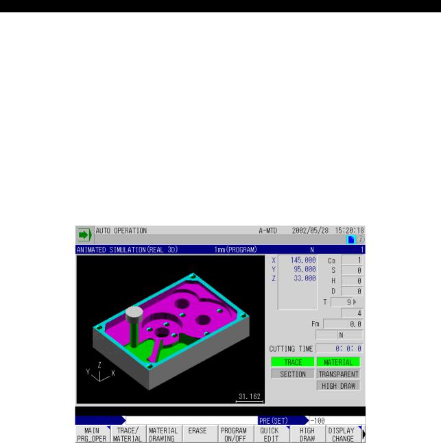
The real 3D simulation function provides animated simulation (3D), which graphically displays realistic, three-dimensional images, and animated simulation (2D), which graphically displays two-dimen- sional images.
1.3D Animated Simulation
1-1. ANIMATED SIMULATION Screen
To display the ANIMATED SIMULATION screen, select [F8] (DISPLAY CHANGE) from the automatic operation MDI operation or manual operation function menu to display the DISPLAY CHANGE pop-up window.
Select ANIMATED SIMULATION from this pop-up menu, then select [F7] (2D/3D CHANGE) from the function menu.
Fig.1-1 ANIMATED SIMULATION Screen
EIOEMM6F1001R01
4291-E P-2
SECTION 1 REAL 3D ANIMATED SIMULATION
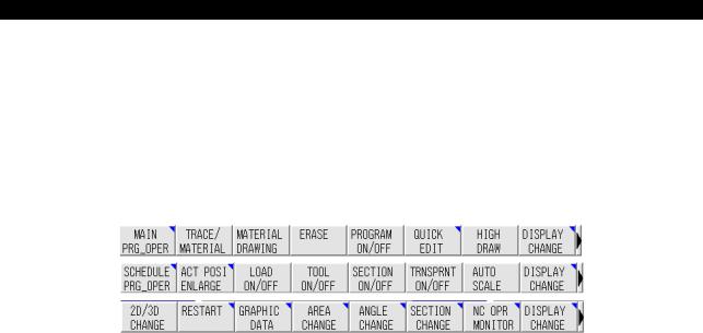
1-1-1. Function Menus
The items in the function menus displayed on the ANIMATED SIMULATION screen are described below.
[Supplement]
If the required function menu is not displayed, press the [EXTEND] key.
According to the pressing of the [EXTEND] key, the following function menu is displayed one by one.
EIOEMM6F1002R01
(1)[F2] (TRACE/MATERIAL)
Selects whether or not the tool path and material are displayed on the ANIMATED SIMULATION screen.
TRACE/ANIMATE
The tool path, material, and tool are displayed, and stock removal is also shown.
TRACE
Only the tool path is displayed.
ANIMATE
The material and tool are displayed, and stock removal is also shown. The tool path is not displayed.
(2)[F3] (MATERIAL DRAWING)
Displays the material provided its display is also selected with [TRACE/MATERIAL].
(3)[F4] (ERASE)
Erases the tool path and material shape displayed in the graphic screen.
(4)[F1] (2D / 3D CHANGE)
Selects the mode of display between 3D and 2D animation.
(5)[F5] (SECTION ON/OFF)
Switches the sectional display of the material in the animation display area on and off.
[Supplement]
Section of the material is displayed according to the setting at the SECTION CHANGE window or that for PLANE and SECTION POS at page 3 of the GRAPHIC DATA screen.
(6)[F6] (TRANSPRNT ON/OFF)
Switches transparent display of the material shown in the animation display area on and off.

4291-E P-3
SECTION 1 REAL 3D ANIMATED SIMULATION
(7)[F7] (AUTO SCALE)
Searches the material for which the same spindle position and rotary axis as set at the GRAPHIC DATA window among the registered materials, and automatically calculates and set the animation display area based on the data of the found material.
[Supplement]
1)It is possible to provide margin around the material. This margin is set in percent in reference to the material display area at page 6 of GRAPHIC DATA window.
2)If the material assigned the same conditions is not found, error message of “No blank data” is displayed.
(8)[F3] (GRAPHIC DATA)
The following parameters can be set in the pop-up window displayed by selecting this menu item (the pop-up window has 6 pages).
Page 1/6
Graphic data: Set the conditions used for selecting the material from the registered materials.
Page 2/6
Projection angle: Set the angle of view for display in three dimensions.
Page 3/6
Settings for sectional display: Set the position of the section for sectional display.
Page 4/6
Graphic area settings: Set the graphic area for 3D display. At the PAGE LIMIT field, set whether or not the fourth and subsequent pages of the GRAPHIC DATA pop-up window are displayed.
Page 5/6
Drawing color settings: Set the color of the material and section color for 3D display.
Page 6/6
Graphic data: Set the parameters for 3D display.
4291-E P-4
SECTION 1 REAL 3D ANIMATED SIMULATION
(9)The data set on each page of the GRAPHIC DATA pop-up window are indicated in the table below.
Page |
Data |
|
|
Setting Range |
|
|
|
|
|
||
|
SPINDLE DIRECTION |
|
V, HF, HL, HB, HR |
||
|
|
|
|
||
1 |
ROTARY AXIS |
|
NO SETTING, A, B, C |
||
|
|
|
|
||
ROTARY AXIS ANGLE |
0 |
~ 359 (deg) |
|||
|
|||||
|
|
|
|
|
|
|
GRAPHIC COORDINATE NUMBER |
0 |
~ specified maximum value |
||
|
|
|
|
|
|
2 |
PAN |
0 |
~ 359 (deg) |
||
|
|
|
|
||
TILT |
|
-89 ~ 89 (deg) |
|||
|
|
||||
|
|
|
|
||
3 |
SECTION PLANE |
|
X-Y, Y-Z, Z-X |
||
|
|
|
|
||
SECTION POS. XYZ |
|
-99999.999 ~ 99999.999 (mm) |
|||
|
|
||||
|
|
|
|
||
|
AREA DATA (CENTER) |
|
-9999.999 ~ 9999.999 (mm) |
||
|
|
|
|
||
4 |
AREA DATA (WIDTH) |
|
4.000 ~ 9999.999 (mm) |
||
|
|
|
|
||
|
PAGE LIMIT |
|
EXIST, NONE |
||
|
|
|
|
||
|
MANUAL FEED TRACE |
|
Black, blue, green, cyan, red, magenta, |
||
|
|
|
yellow, gray |
||
|
RAPID FEED TRACE |
|
|||
|
|
|
|
||
|
|
|
|
|
|
5 |
CUTTING FEED TRACE |
|
|
|
|
|
|
|
|
|
|
|
BLANK |
|
|
|
|
|
|
|
|
|
|
|
SECTION |
|
|
|
|
|
|
|
|
||
|
FRAME MOVING UNIT CHANGE |
1 |
~ 16 (dot) |
||
|
|
|
|
||
|
RATIO OF ROOM AREA IN AUTO |
0 |
~ 100 (%) |
||
6 |
SCALE |
|
|
|
|
|
|
|
|
||
ANGLE CHANGE PITCH (PAN) |
1 |
~ 30 (deg) |
|||
|
|||||
|
|
|
|
||
|
ANGLE CHANGE PITCH (TILT) |
1 |
~ 30 (deg) |
||
|
|
|
|
||
|
SECTION MOVING INTERVAL |
0 |
~ 99999.999 (mm) |
||
|
|
|
|
|
|
(10)[F4] (AREA CHANGE)
Set the area in which the material is to be displayed in the pop-up window displayed by selecting this menu item.
While viewing the material and the frame indicating the drawing range in the window, use the up/down/left/right cursor keys, the page keys and the [F1] (MAGNI) and [F2] (REDUCE) function keys to change the position and size of the frame.
Pressing a cursor key causes the center of the graphic to shift by the number of dots set for “FRAME MOVING UNIT” on page 6/6 of the GRAPHIC DATA pop-up window.
The frame indicating the drawing range is enlarged or reduced according to the pressing of the page keys and the [F1] (MAGNI) and [F2] (REDUCE) function keys.
(11)[F5] (ANGLE CHANGE)
Set the angle from which the material is to be viewed (projection angle) in the pop-up window displayed by selecting this menu item.
The cube displayed in the pop-up window can be rotated by using the up/down/left/right cursor keys function keys ([F1] (DOWN ROTARY), [F2] (UP ROTARY), [F3] (RIGHT ROTARY), [F4] (LEFT ROTARY)) to set the projection angle.
Use the up/down cursor keys or function keys ([F1] (DOWN ROTARY), [F2] (UP ROTARY)) to rotate the graphic in the up/down direction and the right/left cursor keys or function keys ([F3] RIGHT ROTARY, [F4] (LEFT ROTARY)) to rotate the graphic in the left/right direction.
Each time a key is pressed, the graphic is rotated by the angular increment set for “ANGLE CHANGE PITCH” on page 6/6 of the GRAPHIC DATA pop-up window.

4291-E P-5
SECTION 1 REAL 3D ANIMATED SIMULATION
(12)[F6] (SECTION CHANGE)
Set the position of the displayed section through the material in the pop-up window displayed by selecting this menu item.
In the “SECTION CHANGE” window to the right of the pop-up window, you can choose to set the section to be displayed by moving the cursor on the screen, or to select the position of the section in each plane.
To set the plane of the section to be displayed, select [F1] (Y-Z), [F2] (Z-X), or [F3] (X-Y).
The position of the selected section can be shifted by pressing the up/down page keys. The shift increment is set for SECTION MOVING INTERVAL on page 6/6 of the GRAPHIC DATA pop-up window.
To set the position of the section in each plane, use the SET and ADD functions to alter the position values in the setting fields.
[Supplement]
The center of graphic and graphic area in the lower part of the window only serve as a guide for positioning the section (they cannot be set).
1-1-2. General Points Relating to Animation
(1)Animation speed
There is a limit on the feedrate that can be displayed by the animation function.
If the feedrate exceeds this limit during animation, the message “ANIM SPEED OVER” is displayed, and removal of stock and the tool path are not shown.
To clear the “ANIM SPEED OVER” error, perform one of the following:
•Select ERASE.
•Reset the NC.
•Change the range or angle.
1-1-3. High-speed Drawing
Programmed tool paths can be drawn at a high speed when the machine lock mode is set. ON/OFF setting for the single block function is valid during high-speed drawing.
1-1-4. Cutting Time Display
The execution time of a program differs depending on whether or not the machine lock function is set.
(1)Machine lock function ON
Length of timer required for axis movements is calculated at the completion of each block and added. In this calculation, the time spent for the execution of S, T, M commands and G04 is disregarded.
Cutting time is calculated based on the feedrates that are obtained by “programmed F value x override value (the value valid at the start of a block)”. For rapid feed operation, time is calculated assuming override setting of 100%.
(2)Machine lock function OFF
Total machine operating time is calculated.

4291-E P-6
SECTION 1 REAL 3D ANIMATED SIMULATION
1-1-5. Selection of Material Shape and Tool Shape
The material shape and tool shape used for the 3D animated simulation function are included in all programs created using the IGF function, so they are automatically set when a program created using the IGF function is called.
[Supplement]
When the tool shape has to be changed, refer to ANIMATED SIMULATION (2D), Tool Shape Definition.
1-1-6. System Variables
The following system variables can be referred to and updated from an NC program.
Application of System Variable |
System Variable Name |
|
Possible Settings |
|
|
|
|
Section designation |
VSCTA |
0 (Non-sectional display) |
|
|
|
1 |
Y-Z plane |
|
|
2 |
Z-X plane |
|
|
3 |
X-Y plane |
|
|
|
|
Section position designation |
VSCTX |
-99999.999 ~ 99999.999 |
|
|
VSCTY |
-99999.999 ~ 99999.999 |
|
|
VSCTZ |
-99999.999 ~ 99999.999 |
|
|
|
|
|
Transparent display designa- |
VTRSP |
0 |
Standard display |
tion |
|
1 |
Transparent display |
|
|
|
|
1-1-7. Return Search
It is possible to designate if tool path during return search is drawn in 3D animation by selecting [F2] (RESTART) or by the procedure for selecting return search from the MAIN PRG_OPER.
[Supplement]
If return search tool path is drawn, it will take a longer time than the time required for return search without 3D animation drawing.
1-1-8. Processing at the Selection of NC Program
It is possible to set whether or not “automatic scaling” and “material drawing” are automatically executed after reading the NC program. This setting is made when selecting NC program.
1-1-9. Other Considerations
(1)On switching between 2D and 3D animation during execution of a main program, the screen is temporarily cleared, then drawing starts again. Drawing starts from the point where the switchover was made, with no trace of the cutting up to that point remaining.
(2)When the graphic display is displayed in a pop-up window by selecting the ANIMATE ON/OFF function key on screens other than the ANIMATED SIMULATION screen, such as the ACTUAL POSITION screen and program display screens, the type of display (2D or 3D) is determined by the mode selected on the ANIMATED SIMULATION screen.
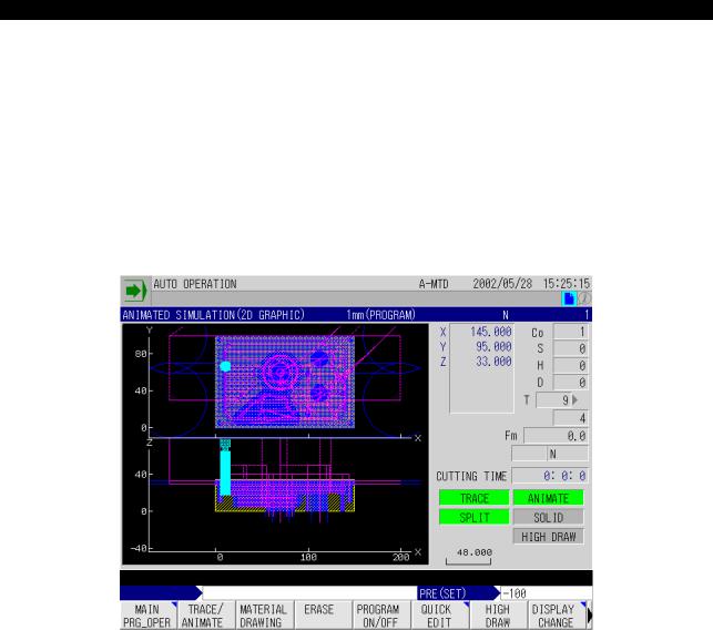
4291-E P-7
SECTION 1 REAL 3D ANIMATED SIMULATION
2.ANIMATED SIMULATION (2D)
2-1. Features and Main Functions
The animated simulation (2D) function displays the tool paths and the portion being machined in graduated painting patterns according to the machined depth, thus simulates the removal of stock from the material.
The animated simulation (2D) function makes the following possible.
•Display of both split view and solid view.
In the display of split view, display in two planes (split display) is possible. Switchover between these two modes of display is possible at any time.
Fig.1-2 Development Display
EIOEMM6F1003R01

4291-E P-8
SECTION 1 REAL 3D ANIMATED SIMULATION
Fig.1-3 Solid View Display
EIOEMM6F1004R01
•In the display of solid figure, you can change the tilting angle and direction angle (pan) as desired while viewing the displayed workpiece. This function enables checking for the progress of machining in the desired direction.
Fig.1-4 Angle Change
EIOEMM6F1005R01
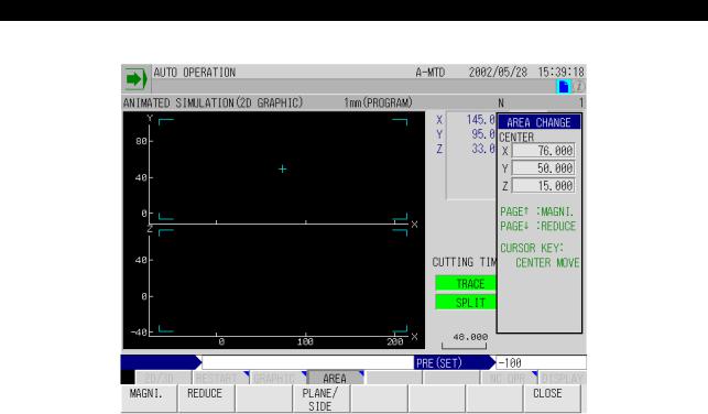
4291-E P-9
SECTION 1 REAL 3D ANIMATED SIMULATION
• Display range can be set as desired for both split view and solid view display.
Fig.1-5 Area Change
EIOEMM6F1006R01
•Pattern of painting differs depending on the depth of cut for the portion being machined.
•The function automatically determines the appropriate range of display according to the size of the material.
•It is possible to set the shape of a cutting tool.
•Animation display is made at the actual cutting feedrate. By turning on the machine lock function, high-speed drawing is possible.
•The function to calculate the cutting time is provided.
•Simulation is also possible for operations including a rotary axis and five-face machining.
•Zero offset, cutter radius compensation, and 3D offset data are automatically calculated and graphic is displayed including them.
•Operation intervention for return search and sequence restart operation.

4291-E P-10
SECTION 1 REAL 3D ANIMATED SIMULATION
2-2. Animated Simulation Screen
2-2-1. Screen Configuration
The animated simulation screen configuration is shown below.
Fig.1-6 Graphic Display Screen Configuration
EIOEMM6F1007R01
On this screen, tool paths and workpiece shape are displayed in the graphic display area. If graphic display and text display overlap, display of text is given priority.
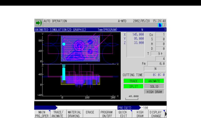
4291-E P-11
SECTION 1 REAL 3D ANIMATED SIMULATION
2-2-2. Items Displayed on the Animated Simulation Screen
Fig.1-7 Animated Simulation Screen
EIOEMM6F1008R01
X, Y, Z
Indicate the actual value of the individual axes in the work coordinate system.
Symbol of “-” is displayed for the axis for which the mirror image is ON.
S, Co, H, D
Indicate the spindle speed (S), the work coordinate system number (Co), the tool length offset number (H) and the cutter radius compensation number (D).
T
Indicates the actual tool number and the next tool number.
Fm
Indicates the feedrate.
CUTTING TIME
Indicates the cutting time.
Cutting time varies depending on whether or not the machine lock function is on.
Machine lock function ON: Length of timer required for axis movements is calculated at the completion of each block and added. In this calculation, the time spent for the execution of S, T, M commands and G04 is disregarded. Cutting time is calculated based on the feedrates that are obtained by “programmed F value x override value (the value valid at the start of a block)”. For rapid feed operation, time is calculated assuming override setting of 100%.
Machine lock function OFF: Total machine operating time is counted. Note that the cutting time data is not cleared until the cycle start switch is pressed at the start of a program.

4291-E P-12
SECTION 1 REAL 3D ANIMATED SIMULATION
TRACE/ANIMATE
Indicate the present mode of the graphic display screen.
•Both TRACE and ANIMATED highlighted
The tool path, material, and tool are displayed, and stock removal is also shown.
•Only TRACE highlighted
Only the tool path is displayed.
•Only ANIMATE highlighted
The material and tool are displayed, and stock removal is also shown.
The tool path is not displayed.
SPLIT/SOLID
Either SPLIT or SOLID is highlighted indicating the present display mode.
(scale)
The line segment and a number shown at the bottom of the graphic data display area indicate the scale. The number shows the length, in the graphic coordinate system, of the displayed line segment.

4291-E P-13
SECTION 1 REAL 3D ANIMATED SIMULATION
2-2-3. Graphic Display
Animation consists of tool path, envelope, enveloped figure, material, and position tool.
Position tool (2)
Envelope (3)
Material
Tool path (1)
Fig.1-8 Graphic Display in Solid View Mode
EIOEMM6F1009R01
(Top View)
 Material
Tool path (1)
Envelope (3) |
Position tool (2) |
Enveloped figure (4) |
Tool path (1)
(Side View)
Material
Fig.1-9 Graphic Display in Split View Mode
EIOEMM6F1010R01
(1)Tool path
Shows the tool path.
Tool path is shown in the following three line types according to the mode of axis feed.
Rapid feed |
Short dash line |
|
Cutting feed |
Solid line |
|
|
||
Jog feed |
Alternate short and long dash line |
|
EIOEMM6F1011R01
•Color designation for tool path is made at the GRAPHIC DATA window. Using different color for tool paths of different axis feed modes is not allowed.
•Whether or not the tool paths of the individual feed modes (rapid feed for positioning, cutting feed and jog feed) are drawn can be set at the GRAPHIC DATA window.
Loading...