


CNC SYSTEM
OSP-P200M/P200MA
5-AXIS MACHINING FUNCTION
INSTRUCTION MANUAL
(5th Edition)
Pub. No. 5611-E-R4 (ME61-214-R5) Jan. 2011

PART 1 5-AXIS MACHINING FUNCTION
SECTION 1 ACTUAL POSITION DISPLAY...................................................2
SECTION 2 MANUAL FEED FUNCTION ......................................................8
SECTION 3 TOOL CENTER POINT CONTROL .........................................20
SECTION 4 TOOL AXIAL DIRECTION TOOL LENGTH COMPENDSATION ......32
SECTION 5 TOOL SIDE COMPENSATION................................................40
SECTION 6 LEADING EDGE COMPENSATION........................................48
SECTION 7 TOOL ATTITUDE COMMAND FUNCTION .............................60
SECTION 8 TOOL POSTURE COMPENSATION FUNCTION...................72
SECTION 9 ROTARY AXIS PIVOT DISTANCE COMPENSATION
FUNCTION ...............................................................................81
SECTION 10 SLOPE MACHINING FUNCTION 2.........................................88
PART 2 PARAMETERS
SECTION 1 ROTARY AXIS PARAMETERS............................................. 151
PART 3 PROCEDURES FOR MEASURING AND SETTING ROTARY
AXIS CENTER POSITION
SECTION 1 TWO ROTARY AXES ON THE TABLE (ROTARY
C-AXIS/INCLINED A-AXIS)................................................... 158
SECTION 2 TABLE AXIS AND SPINDLE AXIS (ROTARY C-AXIS
ON THE TABLE AND INCLINED A- OR B-AXIS OF THE
SPINDLE) .............................................................................. 167
SECTION 3 TWO SPINDLE AXES
(ROTARY C-AXIS/INCLINED B-AXIS) ................................. 180
SECTION 4 TWO TABLE AXES (ROTARY A-AXIS/INCLINED B-AXIS) . 192

Table of Contents
PART 1 5-AXIS MACHINIG FUNCTION
SECTION 1 ACTUAL POSITION DISPLAY...................................................2
1. Overview .................................................................................................................................. 2
2. ACTUAL POSITION display..................................................................................................... 2
2-1. Display of Various Types of Coordinate Systems ......................................................................... 2
2-2. Display of Status Indicator Lamp................................................................................................... 7
SECTION 2 MANUAL FEED FUNCTION ......................................................8
1. Tool Axial Direction Manual Feed and Perpendicular to the Tool Axial Direction Manual Feed......... 8
1-1. Overview ........................................................................................................................................ 8
1-2. Operation .......................................................................................................................................9
1-3. Screen Display............................................................................................................................. 10
2. Table Coordinate Manual Feed.............................................................................................. 14
2-1. Overview ......................................................................................................................................14
2-2. Operation ..................................................................................................................................... 15
3. Tool Nose Center Manaul Feed.............................................................................................. 16
3-1. Overview ......................................................................................................................................16
3-2. Operation ..................................................................................................................................... 16
4. Other Optional Functions ....................................................................................................... 18
4-1. I-MAP ........................................................................................................................................... 18
4-2. Manual Gauging...........................................................................................................................18
4-3. Interactive Gauging...................................................................................................................... 18
4-4. Manual Angle/Circle Feed ........................................................................................................... 18
5. Alarm List................................................................................................................................ 19
5-1. Alarm A......................................................................................................................................... 19
5-2. Alarm D ........................................................................................................................................19
SECTION 3 TOOL CENTER POINT CONTROL .........................................20
1. Overview ................................................................................................................................ 20
1-1. Definition of the coordinate system for the table having a rotary axis ........................................ 21
2. Program Commands.............................................................................................................. 22
2-1. Command Format........................................................................................................................ 22
2-2. Program Commands in G169 Mode ...........................................................................................25
3. System Variables.................................................................................................................... 27
4. Operation in Zero Setting Screen........................................................................................... 27
5. Operation in Tool Length Offset / Cutter Radius Compensation Screen................................ 27
6. Parameters............................................................................................................................. 28
7. Optional Functions ................................................................................................................. 28

7-1. I-MAP ........................................................................................................................................... 28
7-2. Real 3D Animated Simulation...................................................................................................... 28
7-3. Measurement Cycle..................................................................................................................... 28
7-4. Collision Avoidance System ........................................................................................................ 28
8. Alarm List................................................................................................................................ 29
8-1. Alarm A......................................................................................................................................... 29
8-2. Alarm B......................................................................................................................................... 29
8-3. Alarm D ........................................................................................................................................30
8-4. Error .............................................................................................................................................31
SECTION 4 TOOL AXIAL DIRECTION TOOL LENGTH
COMPENDSATION..................................................................32
1. Overview ................................................................................................................................ 32
2. Program Commands.............................................................................................................. 33
2-1. Command Format........................................................................................................................ 33
2-2. Program Commands in G171 Mode ...........................................................................................34
2-3. Points to be Noted ....................................................................................................................... 35
3. Parameters............................................................................................................................. 36
4. Alarm List................................................................................................................................ 37
4-1. Alarm A......................................................................................................................................... 37
4-2. Alarm B......................................................................................................................................... 38
4-3. Alarm D ........................................................................................................................................39
SECTION 5 TOOL SIDE COMPENSATION................................................40
1. Overview ................................................................................................................................ 40
2. Program Command................................................................................................................ 40
2-1. Command Format........................................................................................................................ 40
2-2. Tool Side Compensation Mode and Other Command Modes .................................................... 41
2-3. Commands during Tool Side Compensation Mode ....................................................................41
3. Tool Movement During the Tool Side Compensation ............................................................. 42
4. Parameter............................................................................................................................... 43
5. Points to be Noted.................................................................................................................. 43
6. Alarm List................................................................................................................................ 44
6-1. Alarm B......................................................................................................................................... 44
SECTION 6 LEADING EDGE COMPENSATION........................................48
1. Overview ................................................................................................................................ 48
2. Program Command................................................................................................................ 49
2-1. Command Format........................................................................................................................ 49
2-2. Movement upon entering the leading edge compensation mode............................................... 49
2-3. Movement during the leading edge compensation is on ............................................................50
2-4. Movement upon exiting the Leading Edge Compensation mode............................................... 51

2-5. Compensation Direction .............................................................................................................. 52
2-6. Functions forbidden while Leading Edge Compensation mode is ON ....................................... 53
2-7. Functions disable leading edge compensation ........................................................................... 54
3. Parameter............................................................................................................................... 55
4. Alarm list................................................................................................................................. 55
SECTION 7 TOOL ATTITUDE COMMAND FUNCTION .............................60
1. Overview................................................................................................................................. 60
2. Program Command................................................................................................................ 61
2-1. Command Format........................................................................................................................ 61
2-2. Parameter .................................................................................................................................... 62
2-3. How to Determine Angle.............................................................................................................. 65
3. Alarm List................................................................................................................................ 69
3-1. Alarm A......................................................................................................................................... 69
3-2. Alarm B......................................................................................................................................... 69
3-3. Alarm D ........................................................................................................................................71
SECTION 8 TOOL POSTURE COMPENSATION FUNCTION...................72
1. Overview................................................................................................................................. 72
2. Procedures............................................................................................................................. 73
2-1. Specification using parameter setting.......................................................................................... 74
3. Alarm List................................................................................................................................ 79
SECTION 9 ROTARY AXIS PIVOT DISTANCE COMPENSATION
FUNCTION ...............................................................................81
1. OVERVIEW............................................................................................................................ 81
2. Parameter Setting .................................................................................................................. 83
2-1. Pivot Distance Compensation .....................................................................................................83
2-1-1. Spindle Center......................................................................................................................... 85
2-1-2. Table Center ............................................................................................................................ 86
SECTION 10 SLOPE MACHINING FUNCTION 2.........................................88
1. Overview ................................................................................................................................ 88
2. Slope Coordinate Conversion Command .............................................................................. 89
2-1. Overview ......................................................................................................................................89
2-2. Program command ......................................................................................................................90
2-2-1. Euler angles ............................................................................................................................ 91
2-2-2. Roll - Pitch - Yaw Angles ......................................................................................................... 92
2-2-3. 3 Points ...................................................................................................................................93
2-2-4. 2 Vectors ................................................................................................................................. 94
2-2-5. Projection ................................................................................................................................ 95
2-2-6. Tool Axis Direction................................................................................................................... 96

2-2-7. Rotary Center Axis .................................................................................................................. 98
2-2-8. X, Y, Z-axis ..............................................................................................................................99
2-2-9. Slope Cancel......................................................................................................................... 100
2-2-10. G codes and mnemonic codes used during slope coordinate conversion ........................101
2-2-11. Upper limit restoration (M52) .............................................................................................. 102
2-2-12. axis command cancel ......................................................................................................... 102
2-2-13. pulse handle override..........................................................................................................102
2-3. Screen display ...........................................................................................................................103
2-3-1. Current position display ........................................................................................................103
2-3-2. Shift amount display.............................................................................................................. 103
2-4. Coordinate conversion in the manual operation mode .............................................................103
2-5. Program example ......................................................................................................................104
2-5-1. Usage example of Euler angle .............................................................................................104
2-5-2. Usage example of 3 points ...................................................................................................105
2-6. Parameter setting.......................................................................................................................106
2-6-1. Slope machining parameter.................................................................................................. 106
2-6-2. NC optional parameter (slope machining function).............................................................. 108
2-7. Alarm List ...................................................................................................................................109
2-7-1. Alarm B .................................................................................................................................. 109
3. Slope Indexing command..................................................................................................... 112
3-1. Overview .................................................................................................................................... 112
3-2. Indexing example for each machine type.................................................................................. 113
3-2-1. Two table axes type .............................................................................................................. 113
3-2-2. Table and spindle type .......................................................................................................... 113
3-2-3. Two spindle axes type........................................................................................................... 114
3-3. Command format (G467)........................................................................................................... 115
3-4. Slope indexing operation and program sample ........................................................................ 115
3-4-1. G467 P0 ................................................................................................................................ 115
3-4-2. G467 P1 ................................................................................................................................ 117
3-5. System variable ......................................................................................................................... 119
3-6. Parameter .................................................................................................................................. 120
3-6-1. Rotary axis indexing range (NC axis)................................................................................... 120
3-6-2. Rotary Axis Indexing Range (Attachment) ...........................................................................122
3-6-3. Rotary Axis Indexing .............................................................................................................124
3-7. How to choose the indexing angle ............................................................................................ 125
3-8. Alarm List ...................................................................................................................................127
3-8-1. Alarm B ....................................................................................................................................................................................127
4. I-MAP function for Slope ...................................................................................................... 128
4-1. Overview ....................................................................................................................................128
4-1-1. Features...................................................................................................................................................................................128
4-2. Loading the slope pattern selection screen............................................................................... 130
4-3. Operation on the slope pattern selection screen....................................................................... 133

4-3-1. Pattern selection ...................................................................................................................133
4-3-2. Data setting ...........................................................................................................................135
4-4. Setting item and program format on screens of “Slope (G469)”...............................................136
4-4-1. Euler Angles ..........................................................................................................................136
4-4-2. Roll - Pitch - Yaw Angles ....................................................................................................... 136
4-4-3. 3 Points .................................................................................................................................137
4-4-4. 2 Vectors ...............................................................................................................................138
4-4-5. Projection .............................................................................................................................. 139
4-4-6. Tool Axial Direction................................................................................................................ 139
4-4-7. Rotary Center Axis ................................................................................................................ 140
4-4-8. XYZ Axis................................................................................................................................140
4-4-9. Slope Cancel......................................................................................................................... 141
4-4-10. Slope Indexing .................................................................................................................... 141
4-4-11. Outline explanation of messages........................................................................................ 142
4-4-12. Supplementary note............................................................................................................ 143
4-5. Setting item and program format on screens of “Slope (G69)”................................................. 144
4-5-1. Slope (G69)...........................................................................................................................144
4-5-2. Slope Cancel (G68) ..............................................................................................................145
4-5-3. Outline explanation of messages .........................................................................................145
4-5-4. Supplementary note.............................................................................................................. 145
4-6. Convert....................................................................................................................................... 146
4-6-1. Conversion example .............................................................................................................146
4-6-2.Supplementary note............................................................................................................... 149
_Toc278589520
PART 2 PARAMETERS
SECTION 1 ROTARY AXIS PARAMETERS............................................. 151
1. ROTARY AXIS PARAMETERS............................................................................................ 151
1-1. Rotary Axis Attribute................................................................................................................... 151
1-2. Rotation Center..........................................................................................................................154
1-3. Pivot Distance Compensation ...................................................................................................156
_Toc278589526
PART 3 PROCEDURES FOR MEASURING AND SETTING ROTARY
AXIS CENTER POSITION
SECTION 1 TWO ROTARY AXES ON THE TABLE (ROTARY
C-AXIS/INCLINED A-AXIS)................................................... 158
1. OVERVIEW.......................................................................................................................... 158
2. MEASURING ROTARY AXIS CENTER POSITION ............................................................ 158
2-1. Measuring the Position of the C-axis Rotation Center.............................................................. 159
2-2. Measuring the Position of the A-axis Rotation Center ..............................................................160

3. SETTING ROTARY AXIS PARAMETERS........................................................................... 162
3-1. Setting Values on the Pivot Distance Compensation Display................................................... 163
3-2. Setting Values on the Rotation Center Display .........................................................................165
SECTION 2 TABLE AXIS AND SPINDLE AXIS
(ROTARY C-AXIS ON THE TABLE AND
INCLINED A- OR B-AXIS OF THE SPINDLE)...................... 167
1. OVERVIEW.......................................................................................................................... 167
2. MEASURING ROTARY AXIS CENTER POSITION ............................................................ 168
2-1. Measuring the Position of the C-axis Rotation Center.............................................................. 169
2-2. Measuring the Position of the A-axis Rotation Center (MILLAC-800VH, etc.) .........................170
2-3. Measuring the Position of the B-axis Rotation Center (MILLAC-1000VH, etc.) .......................172
3. SETTING ROTARY AXIS PARAMETERS........................................................................... 174
3-1. Setting Values on the Pivot Distance Compensation Display................................................... 175
3-2. Setting Values on the Rotation Center Display .........................................................................178
SECTION 3 TWO SPINDLE AXES
(ROTARY C-AXIS/INCLINED B-AXIS) ................................. 180
1. OVERVIEW.......................................................................................................................... 180
2. MEASURING ROTARY AXIS CENTER POSITIONS.......................................................... 180
2-1. Measuring the B-axis Rotation Center Position ........................................................................181
2-2. Measuring the C-axis Rotation Center Position ........................................................................ 184
3. SETTING ROTARY AXIS PARAMETERS ........................................................................... 187
3-1. Setting Values on the Pivot Distance Compensation Display................................................... 188
3-2. Setting Values on the Rotation Center Display .........................................................................190
SECTION 4 TWO TABLE AXES (ROTARY A-AXIS/INCLINED
B-AXIS).................................................................................. 192
1. OVERVIEW.......................................................................................................................... 192
2. MEASURING ROTARY AXIS CENTER POSITION ............................................................ 192
2-1. Measuring the Position of the A-axis Rotation Center ..............................................................193
2-2. Measuring the Position of the B-axis Rotation Center ..............................................................195
3. SETTING ROTARY AXIS SYSTEM PARAMETERS ........................................................... 197
4. SETTING ROTARY AXIS PARAMETERS........................................................................... 198
4-1. Setting Values on the Rotary Axis Attribute Display .................................................................. 199
4-2. Setting Values on the Pivot Distance Compensation Display................................................... 200
4-3. Setting Values on the Rotation Center Display .........................................................................202

PART 1 5-AXIS MACHINING FUNCTION
- 1 -
SECTION 1 ACTUAL POSITION DISPLAY
1. Overview
This manual explains about the displays of coordinate values and status indicators used in the 5-axis
machining functions in the AUTO, MDI, and MANUAL modes.
2. ACTUAL POSITION display
2-1. Display of Various Types of Coordinate Systems
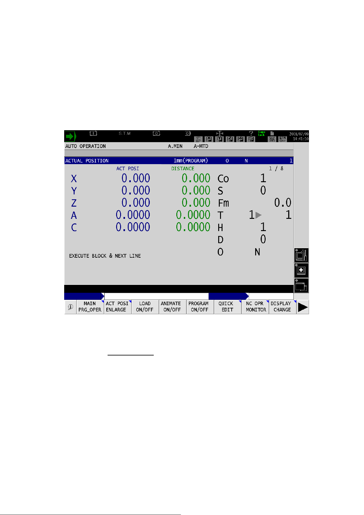
(1) Actual Position Display of Current Coordinate System
Fig. 1-1 Actual position display screen of current coordinate system
The second page of the actual position display under the operation mode screen shows the coordi-
nate values of the currently selected
The current position display function is available for the following types of coordinate systems:
- Local coordinate system
- Work coordinate system
- Slope coordinate system
- Slope local coordinate system
- Table coordinate system
You can check which coordinate system is currently selected in the comment next to the ACT POSI
and DISTANCE at top of the screen.
coordinate system.
- 2 -
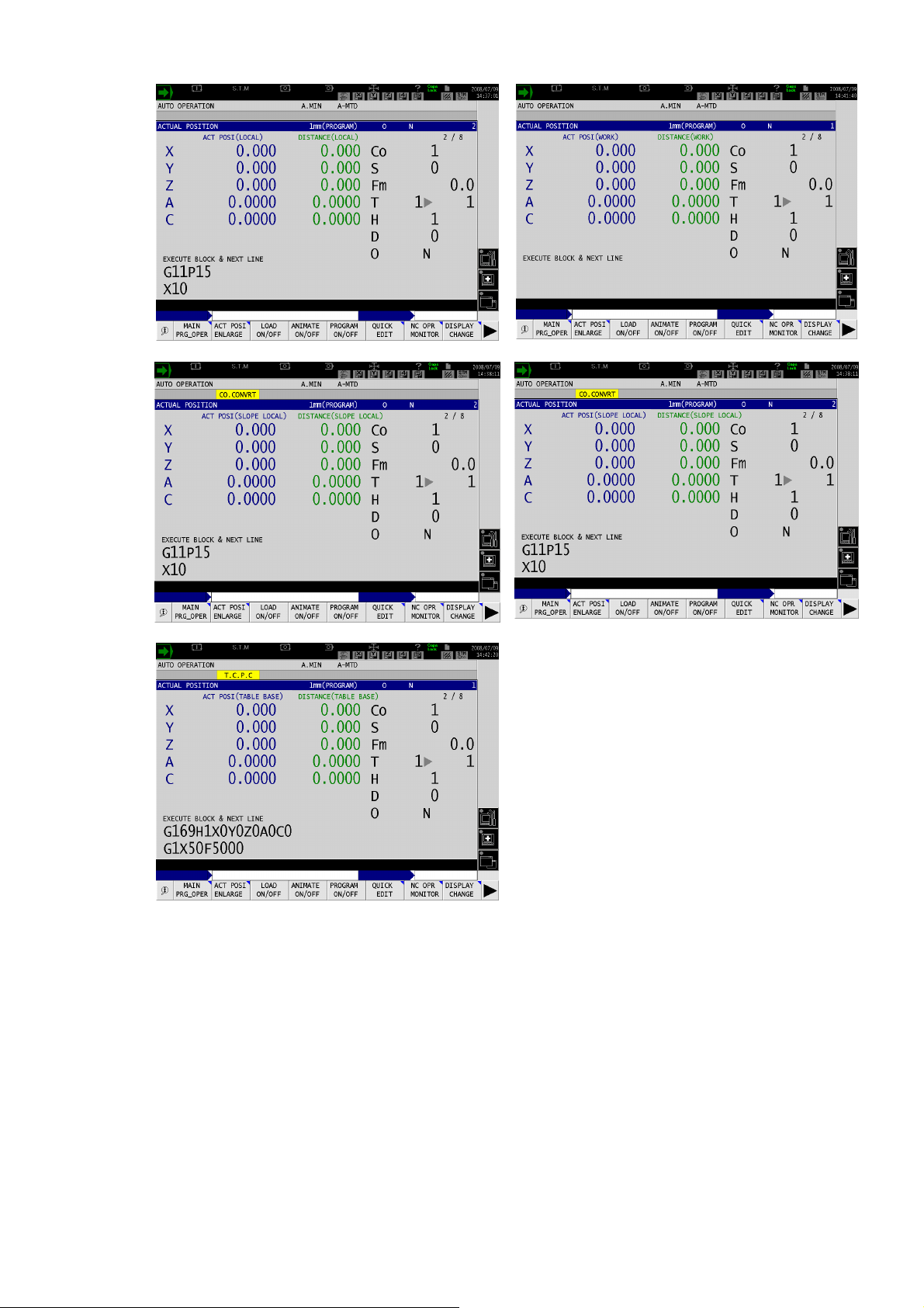
Fig. 1-2 Local coordinate system
Fig. 1-4 Slope coordinate system
Fig. 1-3 Work coordinate system
Fig. 1-5 Slope local coordinate system
Fig. 1-6 Table coordinate system
The display shows the coordinate values of up to 6 axes including linear and rotary axes in one page.
For X, Y, and Z-axes, coordinate system is converted and displayed. For rotary and the additional lin-
ear axes, the current positions of the work coordinate system are to be displayed.
- 3 -
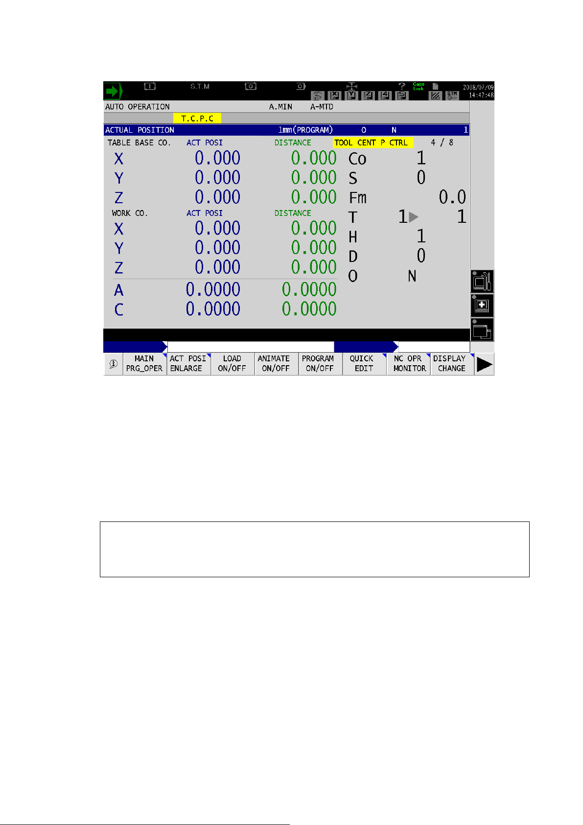
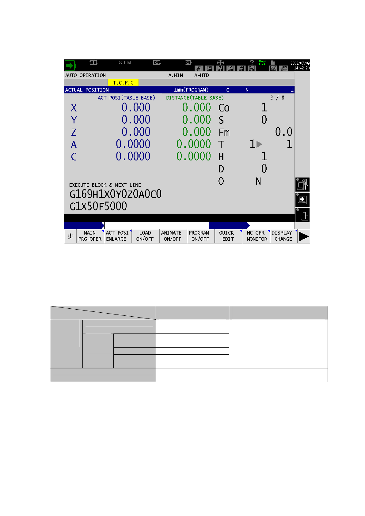
(2) Actual Position of Table Coordinate System
Fig. 1-7 Actual Position of Table Coordinate System
The display shows the coordinate values of the table coordinate system and work coordinate system
in one page. The current position and distance to the target are shown for both coordinate systems.
The rotary axis is only on the Table side and it is shown in the work coordinate system. Indicator
lamp saying T. C. P. C. that indicates that the system is in the tool center point control mode is
shown at the right top, to the left of the page number.
[Supplement]
1) This screen appears when the following conditions are met:
- Tool nose point control, manual feed of tool nose center, or manual feed of table basic coordinate is effective.
- The machine is constructed so that the table has a rotary axis.
- 4 -
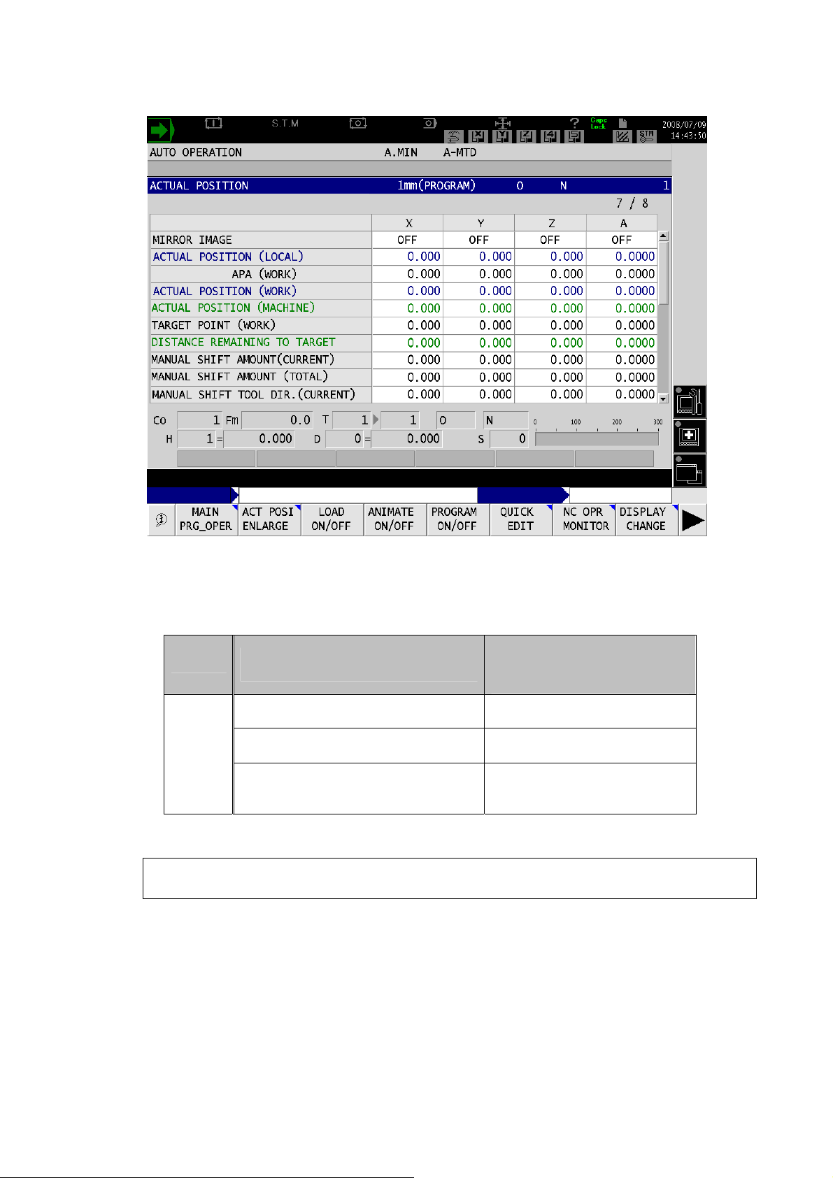
(3) Actual Position, APA, Shift Amount, Target Point, and Distance to Target at a Glance
Fig. 1-8 Display Screen for Actual Position of Each Coordinate System, APA, Shift Amount, Target Point, Dis-
tance Remaining to Target, etc.
Following items will be on the display according to the set specification.
Tool Center Point Control
Tool Nose Center Manual Feed
Function
Tool axial direction
manual feed
Table Coordinate Manual Feed
Current Position
(Table Coordinate)
Distance Remaining to Target
(Table Coordinate)
-
Items
MANUAL SHIFT AMOUNT (CURRENT)
MANUAL SHIFT AMOUNT (TOTAL)
RELATIVE ACUTUAL (CURRENT)
POSITION
(TOOL AXIAL DIRECTION)
[Supplement]
1) The above items appear when any of the followings is activated: the tool center point control,
tool axial direction manual feed, tool nose center manual feed, or table coordinate manual feed.
- 5 -
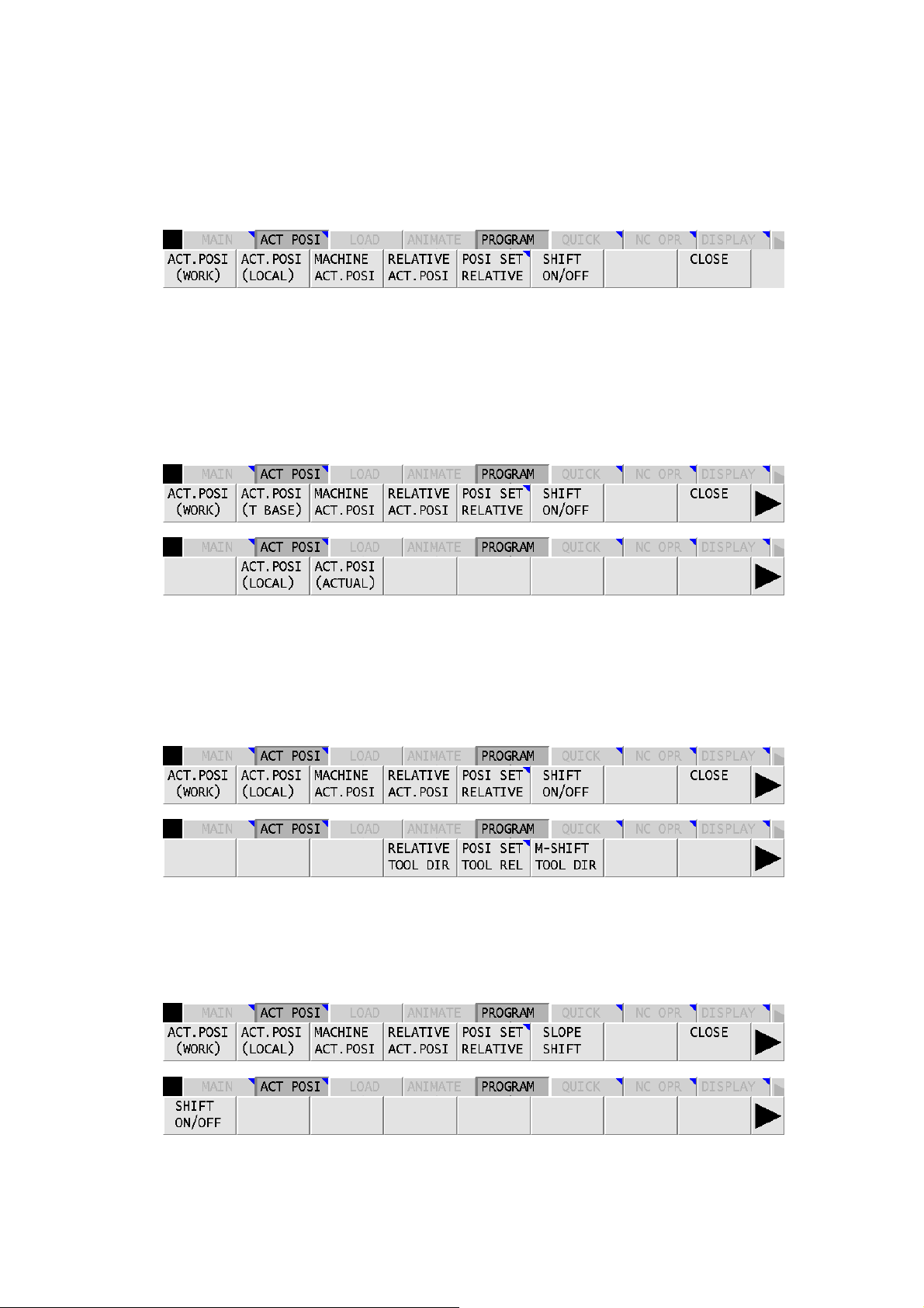
(4) Enlarged Display of Current Position
Press the ACT POSI ENLARGE function under the operation mode to show the pop-up functions
below. Note that pop-up functions differ from the ones for the standard specifications with different
optional specifications.
1) Standard specifications
Fig. 1-9 Function Menu for the Standard Specifications
For TOOL CENTER POINT CONTROL, TOOL NOSE CENTER MANUAL FEED, and TABLE
2)
COORDINATE MANUAL FEED
The [F2] (ACT.POSI (T BASE)) key appears for the function menu of the tool center point control,
tool nose center manual feed, or table coordinate manual feed.
The [F2] (ACT.POSI (LOCAL)) and [F3] (ACT.POSI (ACTUAL)) keys appears in the extended function menu.
Fig. 1-10 Function Menus of Tool Center Point Control, Tool Nose Center Manual Feed, and Table Coor-
dinate Manual Feed
3) For TOOL AXIAL DIRECTION MANUAL FEED
[F4] (RELATIVE TOOL DIR), [F5] (POSI SET TOOL REL), and [F6] (M-SHIFT TOOL DIR) appear
in the extended menu respectively.
Fig. 1-11 Function Menus of Tool Axial Direction Manual Feed
4) For SLOPE MACHINING
The [F6] (SLOPE SHIFT) key appears in the function menu.
The [F1] (SHIFT ON/OFF) key appears in the extended function menu.
Fig. 1-12 Function Menus of Slope Machining
Function menu display differs with different combination of the functions above.
- 6 -
2-2. Display of Status Indicator Lamp
Fig. 1-13 Display of Status Indiactor Lamp
Status indicator lamps available are “CO. CONVET” (slope) for coordinate system is being converted,
“3D FEED” (table coordinate manual feed, tool axial direction manual feed, and tool nose center manual
feed) and “
Manual Interrupt
AUTO,
MDI
operation
mode
Manual operation mode “CO. CONVET” or “3 D FEED” appears according to the setting of
T.C.P.C” that indicates tool center point control is on.
OFF
NC reset status Off
(Nothing on the display)
Program
in progress
During G69
and G469
During G169 T.C.P.C
Others Off
CO. CONVET
(Nothing on the display)
the angle and 3D D FEED switches.
Manual Interrupt
ON
“CO. CONVET” or “3D FEED” appears according to the setting of the
angle and 3D FEED switches.
Note that the status indicator display does not change with ON or OFF status of the pulse override in the
AUTO or MDI operation mode.
- 7 -
SECTION 2 MANUAL FEED FUNCTION
1. Tool Axial Direction Manual Feed and Perpendicular to the Tool Axial Direction
Manual Feed
1-1. Overview
This function is designed for machines with a rotary axis on the spindle side. The function enables manual rapid traverse, manual cutting feed, and manual pulse handle feed of X, Y, and Z-axes when Z-axis is
the tool axial direction. This manual feed function is effective in the index attachments mounted in the
double-column machining center, such as angular attachment, universal attachment, and swivel head.
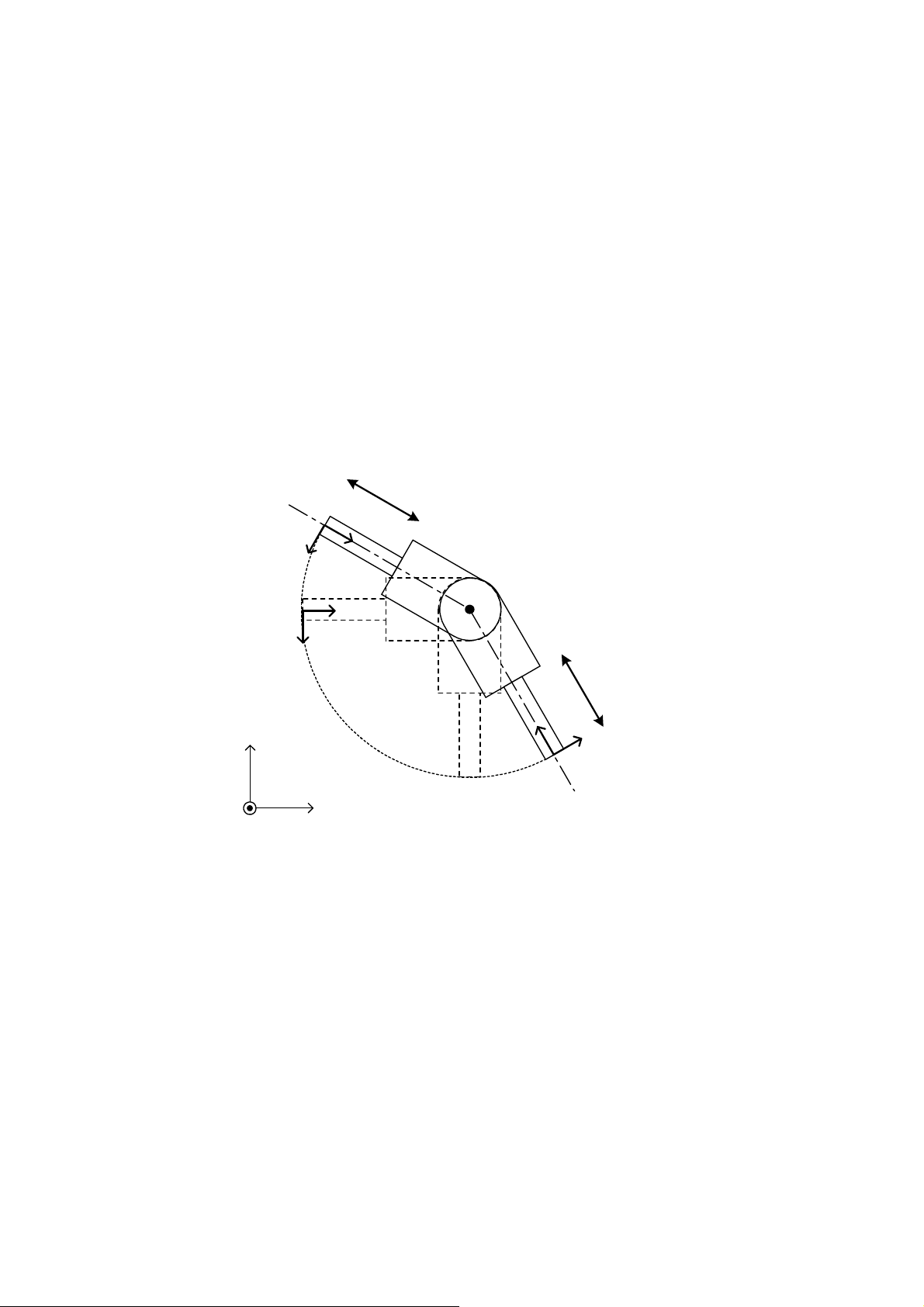
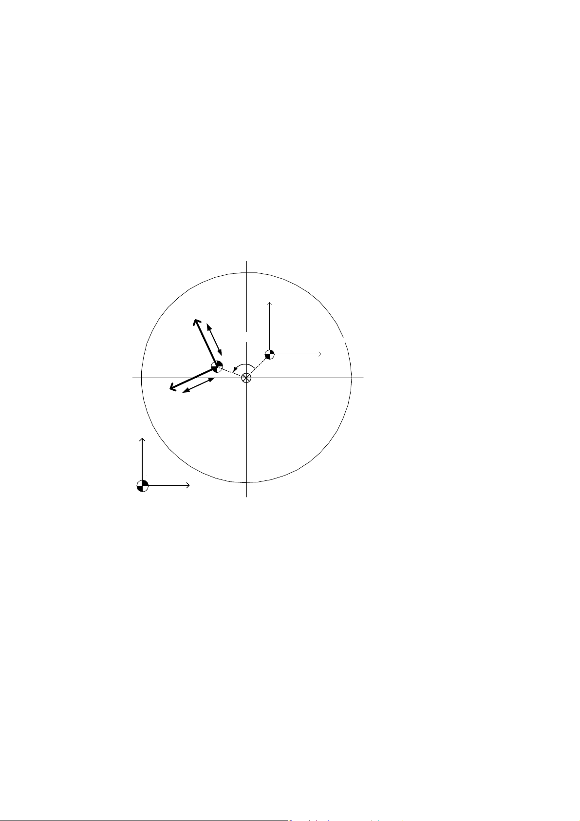
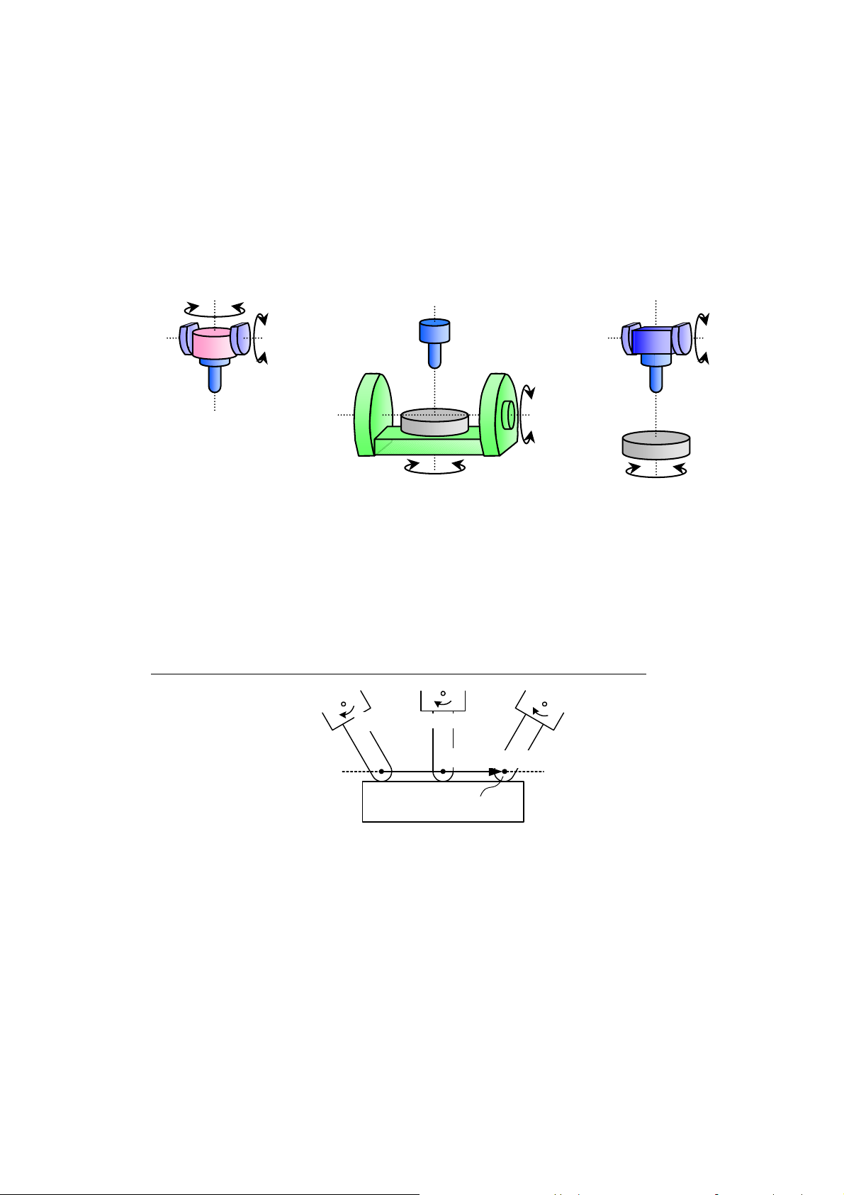
(1) Example of a Machine with A-axis on the Spindle Side
The diagram below shows the relationship between A-axis angle and its feed direction. It is how it appears when you look at the negative direction (-) of the X-axis from the positive (+) direction of the
X-axis. The positive (+) and negative (-) signs are the moving directions when Z-axis is selected for the
tool axial direction manual feed. Moving direction changes with A-axis angle also when Y-axis (the direction perpendicular to the tool spindle) is selected for the tool axial direction manual feed. X-axis is not
dependent on the A-axis angle and it is perpendicular to this document.
-
+
A-120°
Z
Y
Z
A-90°
Y
Z
+
Z
-
Y
A+30°
A0°
X
The multiple rotary axes on the spindle side also move in the tool axial direction and the direction perpendicular to the tool axial direction according to their indexed angle.
Y
Fig. 2-1 (Spindle side) A-axis Angle and Manual Feed Direction
- 8 -

1-2. Operation
(1) MANUAL Operation Mode
Turn on the 3D FEED switch, select the axis out of X, Y, or Z-axis with the MANUAL FEED AXIS
SELECTION key on the machine panel or with the manual pulse handle axis selection switch, and
move the axis in the tool axial direction or direction perpendicular to it.
* The 3D FEED switch is displayed as “3D” on the operation panel depending on models. Regard the
description of 3D FEED below as 3D in that case.
(2) AUTO/MDI Operation Mode
- Pulse Handle Override
If the pulse handle override and the 3D FEED ON/OFF switch are both turned on, “4337
Alarm-D Tool nose center man-feed func is invalid” will appear. While this alarm is ON, it is still
possible to manually feed the axis in the tool axial direction or in the direction perpendicular to it.
However, note that “1336 Alarm-A The manual shift remains. Be warned axis move.” will be
raised if G169 or G171 mode is ON.
- Manual Interrupt
Manual feed in the tool axial direction and the direction perpendicular to it are possible while
manual interrupt mode is ON. However, if the shift amount (total) remains (≠0) when the manual
interruption is turned off in G169/G171 mode, “1336 Alarm-A The manual shift remains. Be
warned axis move” appears. Make sure to set the shift amount (total) to zero manually or with a
sequence restart switch before you exit the manual interrupt mode. (For details, see “TOOL
CENTER POINT CONTROL” and “TOOL AXIAL DIRECTION TOOL LENGTH
COMPENSATION” in this manual)
[CAUTION]
If the machine has rotary axes on the spindle and table sides, the axial movement of X, Y, and
Z-axes fed with the 3D FEED switch differs according to the NC optional parameter bit settings
below. Turn the parameter bit OFF to enable the tool axial manual feed and perpendicular to
the tool axial direction manual feed.
NC Optional Parameter Bit
No. bit Description
Specifies the coordinate system which will be
selected when the three fundamental axes are
78 6
fed manually after the 3D FEED switch is turned
on on the machine with a rotary axis on the spindle side and table side respectively.
Selects the
table base coordinate system.
Selects the
tool axis
coordinate
system.
Initial
status
- 9 -
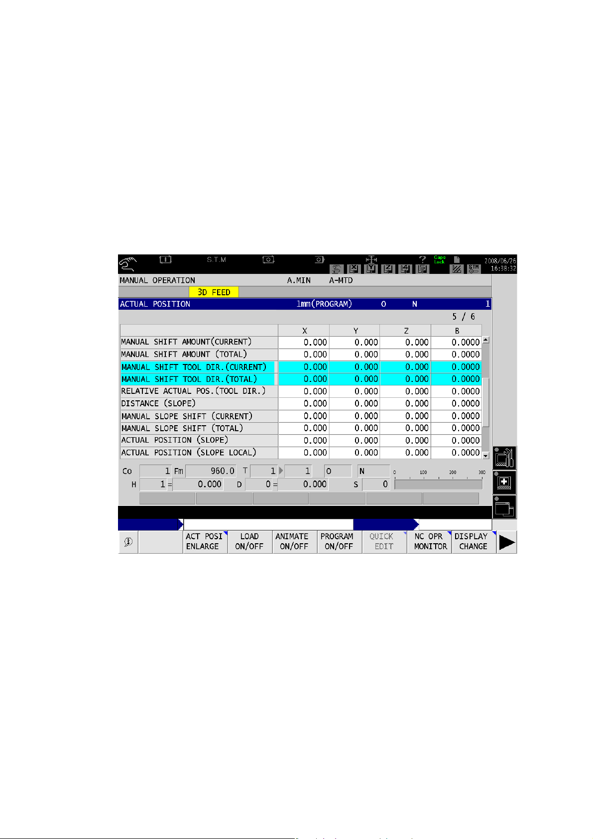
1-3. Screen Display
(1) ACTUAL (CURRENT) Position, APA, Shift amount, Traget position, and Distance remaining to the
target at a Glance
Feed the page of the ACTUAL (CURRENT) POSITION screen under the operation screen to see the informa-
tion on the following items:
- MANUAL SHIFT AMOUNT (CURRENT)
- MANUAL SHIFT AMOUNT (TOTAL)
- RELATIVE CURRENT POSITION (TOOL AXIAL DIRECTION)
MANUAL SHIFT AMOUNT (CURRENT) and MANUAL SHIFT AMOUNT (TOTAL) will be highlighted in
blue when you turn the manual operation mode or manual interrupt ON and the feed in the tool axial direction and the direction perpendicular to it become valid.
When manual feed in the tool axial direction and the direction perpendicular to it are valid:
Fig. 2-2
- 10 -
When manual feed in the tool axial direction and the direction perpendicular to it are valid
(2) Enlarged Current Position Window
Following function keys will appear in the pop-up function opened by [F2] (ACT POSI ENLARGE) under the
operation mode screen.
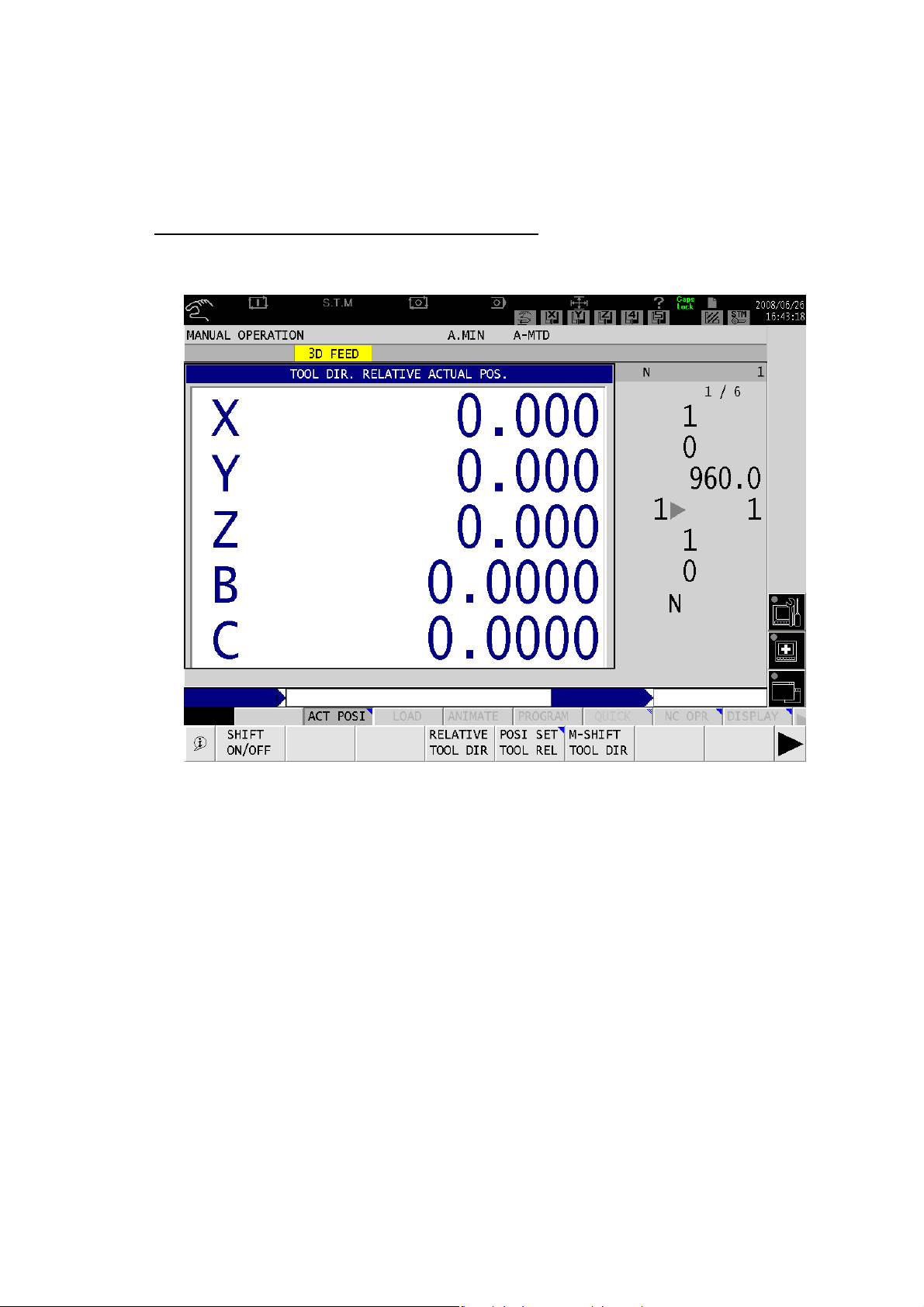
- TOOL DIRECTION RELATIVE ACTUAL (CURRENT) POSITION
- POSITION SET (TOOL)
- TOOL SHIFT ON/OFF
Tool Direction Relative Actual (Current) Position Function
Press the TOOL DIR. RELATIVE ACTUAL POS. function key to open the TOOL DIRECTION
RELATIVE ACTUAL POSITION window. Meanwhile, [F5] (POSI SET TOOL REL).
Fig. 2-3 TOOL DIR. RELATIVE ACTUAL POS. Screen
The window shows the RELATIVE ACTUAL POSITION of the coordinate system whose Z-axis is
the spindle axis. Set the zero point for this coordinate system in the POSITION SET window. Press
the POSITION SET function key to open the window.
- 11 -
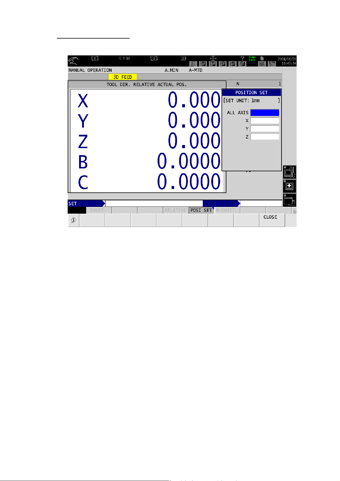
Position Set (Tool) Function
Press the [F5] (POSI SET TOOL REL) key to open the “POSITION SET” window.
Fig. 2-4 POSITION SET Window
When you start the manual interrupt, you can check the distance remaining to the target when you
feed the axis in the tool axial direction by setting the relative current position of the tool axial direction
zero in this window.
If the input data were recognized as numeric data, “Error 5343 Numerical data” will occur.
If the input data were out of the valid numeric data range, “Error 5209 Input data overflow” will occur.
Relative positions will be set for X, Y, and Z-axes when a value is given for ALL AXIS. Values used
for the relative positions for the tool axial direction, the normal relative positions, and the current position of the slope relative position will not be shared.
- 12 -
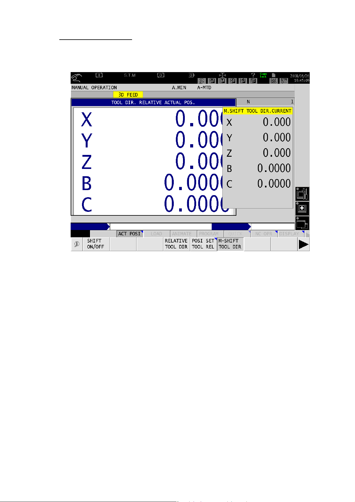
Tool Shift ON/OFF Function
Press the function key to open the M.SHIFT TOOL DIR. CURRENT window. Turn the manual operation
mode or manual interrupt ON. The title on top of the window turns yellow if the manual feed in the tool
axial direction or the direction perpendicular to it is valid.
Fig. 2-5 M. SHIFT TOOL DIR. CURRENT Window
- 13 -
Y
2. Table Coordinate Manual Feed
2-1. Overview
Table coordinate manual feed function is designed for machines with a rotary axis on the table side. The
function enables manual rapid traverse, manual cutting feed, and manual pulse handle feed of X, Y, and
Z-axes for the datum coordinate system of the tilted table or the rotary table.
This function is intended for the NC rotary axis (min. input increment: 0.001° or 0.0001°).
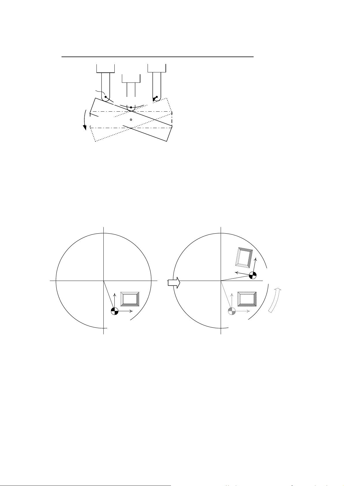
(1) Example of a Machine with C-axis on the Table Side
Following diagram shows the relationship between C-axis angle and its moving direction. It is how it
appears when you look at the negative direction (-) of the Z-axis from the positive (+) direction of the
Z-axis. Table Coordinate System rotates according to the C-axis’s indexed angle. In the example below,
both X- and Y-axes move simultaneously if you attempt to move the X- or Y-axis of the table coordinate
system. Z-axis is independent from the C-axis angle and it is perpendicular to this document.
Y
X
+
X-axis
Operation
テーブル基準
Table
Coordinate
座標系
System
Y
+
Y
X軸操作
-
作
-axis
操
軸
Operation
-
Work Coordinate-
ワーク座標系原点
System
C軸旋回中心
Center of C-axis Rotary
X
Y
Machine
機械座標系
Coordinate System
X
Fig. 2-6 Table Side C-axis Angle and Manual Feed Direction
For machines with multiple rotary axes on the table side, their axial movements are to be according to the
table coordinate system determined by their indexed angles.
- 14 -

2-2. Operation
(1) MANUAL Operation Mode
Turn 3D FEED switch ON and select the desired axis out of X, Y, and Z-axis with the manual feed axis selection key on the machine operation panel or manual pulse handle axis selection switch. The selected axis
will move based on the table coordinate system in manual rapid traverse, manual cutting feed, or manual
pulse handle feed.
(2) AUTO/MDI Operation Mode
Table coordinate manual feed moves in the AUTO/MDI operation mode as follows.
- Pulse Handle Override
If the pulse handle override and the 3D FEED ON/OFF switch are both turned on, “4337
Alarm-D Tool nose center man-feed func is invalid” will appear. While this alarm is ON, it is still
possible to feed the axes in table coordinate manual feed. However, note that “1336 Alarm-A
The manual shift remains. Be warned axis move.” will be raised if G169 or G171 mode is ON.
- Manual Interrupt
Manual feed in the table coordinate is possible while manual interrupt mode is ON. However, if
the shift amount remains (≠0) when the manual interruption is turned off in G169/G171 mode,
“1336 Alarm-A The manual shift remains Be warned axis move” appears. Make sure to set the
shift amount (total) to zero manually or with a sequence restart switch before you exit the manual interrupt mode. (For details, see “TOOL CENTER POINT CONTROL” and “TOOL AXIAL
DIRECTION TOOL LENGTH COMPENSATION” in this manual.)
[CAUTION]
If the machine has rotary axes on the spindle and table sides, the axial movement of X, Y, and
Z-axes fed with the 3D FEED switch differs according to the NC optional parameter bit settings
below. Turn the parameter bit ON to enable the table coordinate manual feed.
NC Optional Parameter Bit
No. bit
Specifies the coordinate system which will be
selected when the three fundamental axes are
78 6
fed manually after the 3D FEED switch is turned
on on the machine with a rotary axis on the spindle side and table side respectively.
Description
Selects the
table base coordinate system.
Selects the
tool axis
coordinate
system.
Initial
status
- 15 -
3. Tool Nose Center Manaul Feed
3-1. Overview
Tool nose center manual feed function is designed for machines with rotary axes on the spindle and table
sides. The function enables the spindle or table rotate around the tool nose center.
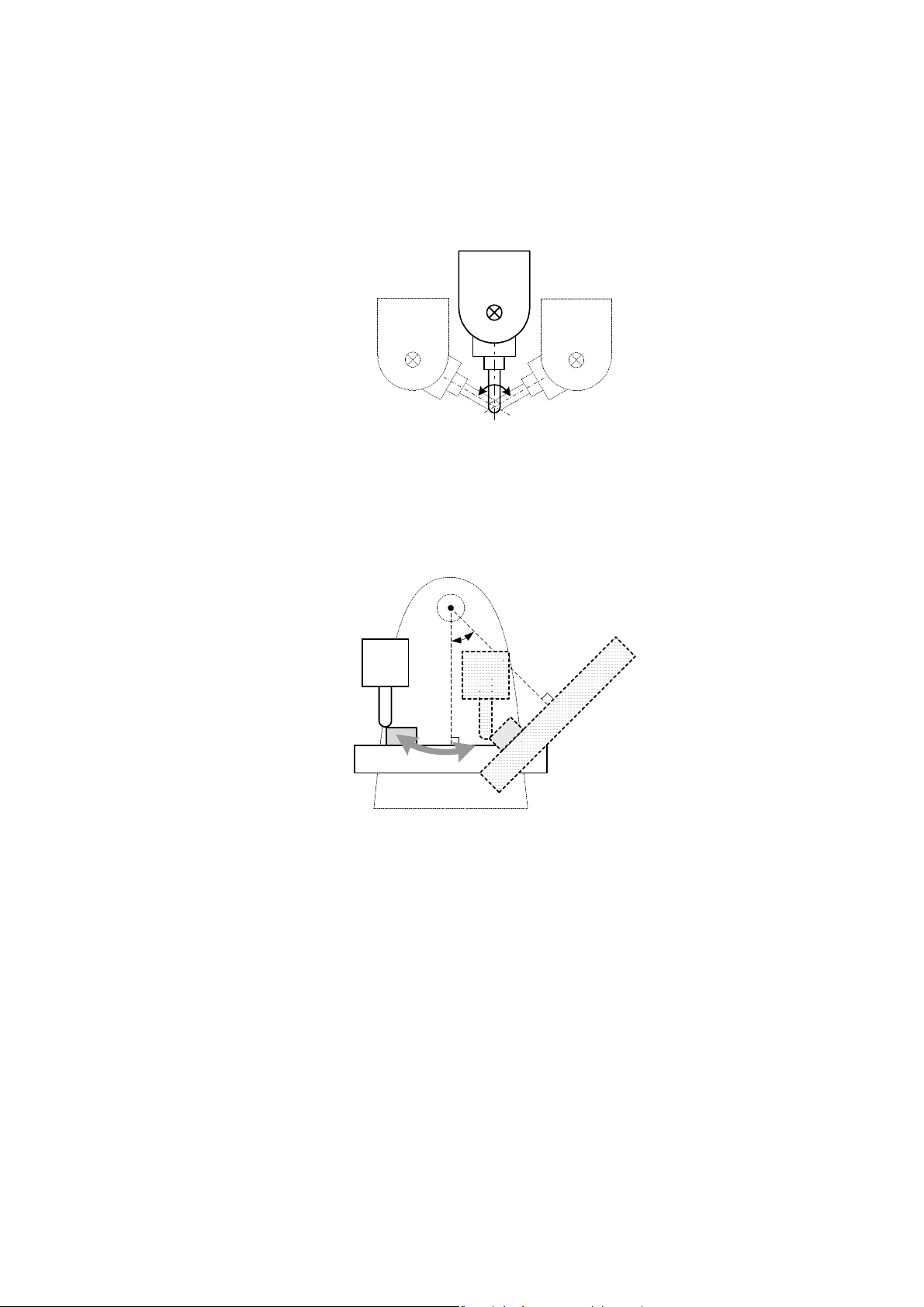
(1) Rotary axis on the spindle side
Spindle rotates around the tool nose center.
Fig. 2-7 Movement of the tool nose center manual feed
(with the rotary axis on the spindle side)
(2) Rotary axis on the table side
Table rotates keeping the tool nose center position seen from the table (work). The tool appears tilting
around tool nose center if you see the tool by reference to the table (work).
Fig. 2-8 Movement of the tool nose center manual feed
(with the rotary axis on the table side)
3-2. Operation
(1) MANUAL Operation Mode
Turn 3D FEED switch ON and select the desired axis out of A, B, and C-axis with the manual feed axis selection key on the machine operation panel or manual pulse handle axis selection switch. The selected axis
will rotate around on the tool nose center in manual rapid traverse, manual cutting feed, or manual pulse
handle feed.
(2) AUTO/MDI Operation Mode
Tool nose center manual feed
moves in the AUTO/MDI operation mode as follows.
- Pulse Handle Override
If the pulse handle override and the 3D FEED ON/OFF switch are both turned on, “4337 Alarm-D
Tool nose center man-feed func is invalid” will appear. While this alarm is ON, manual pulse handle
would not work.
- 16 -

- Manual Interrupt
Manual feed in the table coordinate is possible while manual interrupt mode is ON. However, if the
shift amount remains (≠0) when the manual interruption is turned off in G169/G171 mode, the
“1336 Alarm-A The manual shift remains. Be warned axis move” appears. Make sure to set the
shift amount (total) to zero manually or with a sequence restart switch before you exit the manual
interrupt mode. (For details, see “TOOL CENTER POINT CONTROL” and “TOOL AXIAL
DIRECTION TOOL LENGTH COMPENSATION” in this manual.)
[CAUTION]
■ Tool Length Compensation
If the machine has a rotary axis on the spindle side, the system finds the tool nose position based on
the distance from the center of the rotation of the rotary axis to the spindle nose and the tool length
compensation amount. The found point will be the center of the tool nose center feed movement.
Therefore, make sure that proper tool compensation number is selected for the spindle tool even in
the manual operation. Tool compensation numbers can be specified in the program command (H) in
the AUTO or MDI operation. The number selected there will be kept even after the mode is switched
to manual mode.
■ Stroke End Limit
Linear axes are to move along with the rotary axis in the tool nose center manual feed. When a linear
axis is about to reach the stroke end limit, it stops in the limit vicinity and the rotary axis movement
also stops.
■ Speed Limit
If rotary radius is large in the tool nose center manual feed, the linear axes travel distance becomes
longer. If the rotary axis feedrate is high, the linear axis feedrate also becomes high. To avoid the
linear axis feedrate to be too fast, the rotary axis feedrate limit is controlled based on the rotary radius and the linear axis feedrate limit. In some cases, the rotary axis feedrate limit determined here
may be lower than the feedrate set by the command.
- 17 -

4. Other Optional Functions
4-1. I-MAP
By using the CAL key for the I-MAP PLAYBACK function, it is possible to acquire the actual position of
the currently selected work coordinate system. With the machine having rotary axes on the table, the
current position in the table coordinate system is acquired when manual axis feed in the table coordinate system is effective or the G169 mode is selected with the program command.
4-2. Manual Gauging
Note that axis feed will be tool axial direction manual feed/table coordinate manual feed/tool nose
center manual feed if the 3D FEED switch is ON during manual gauging.
4-3. Interactive Gauging
If the +SINGLE, -SINGLE, or AUTO switch on the operation panel is ON, tool length gauging skip or
work gauging skip will NOT depend on the 3D FEED switch ON/OFF status. Turn on the 3D FEED
switch for manually moving the probe close to the work in the tool axial direction manual feed, table
coordinate manual feed, or tool nose center manual feed.
4-4. Manual Angle/Circle Feed
3D FEED function is not supported for manual angle/circle feed.
- 18 -

5. Alarm List
5-1. Alarm A
1336 The manual shift remains. Be warned axis move.
The shift amount exists in G169 mode or G171 mode.
[Character-string]
None
[Code]
None
[Probable Faulty Locations]
None
[Measures to Take]
1: Cancel the shift amount (total).
2: Change the alarm level to warning by setting data at the NC optional parameter (bit) No.78 bit4.
[Related Specifications]
Tool center point control, Tool axial direction tool length compensation
5-2. Alarm D
4337Tool nose center man-feed func is invalid
Both 3D axis feed switch and pulse handle override were turned on in automatic or MDI operation.
[Character-string]
None
[Code]
None
[Probable Faulty Locations]
None
[Measures to Take]
1: Turn off the 3D axis feed switch or pulse handle override.
[Related Specifications]
Tool nose center manual feed
4338 The manual shift remains. Be warned axis move.
The shift amount exists in G169 mode or G171 mode.
[Character-string]
None
[Code]
None
[Probable Faulty Locations]
None
[Measures to Take]
1: Cancel the shift amount (sum).
[Related Specifications]
Tool nose control, tool length offset in tool axis direction
- 19 -
SECTION 3 TOOL CENTER POINT CONTROL
1. Overview
This function is applicable to the 5-axis machining center having three linear axes X, Y, and Z and
two rotary axes. The function controls the movements of each axis by adding the tool length offset
amount so that the tool center point moves along the workpiece through the tool path specified by
the axis movement commands. It also controls the feedrate of each axis so that tool center point
moves along the workpiece at the specified feedrate.
The rotary axis configuration of 5-axis machining center can be classified into the following three
cases: the spindle has two rotary axes, the table has two rotary axes, and the spindle and the table
have one rotary axis.
Spindle having
two rotary axes
Fig. 3-1 Rotary axis configuration in relation with the tool center point control
Table having two
rotary axes
One rotary axis each for spin-
dle and table
The commands G00 (positioning), G01 (linear interpolation), and G02/G03 (circular interpolation)
can be used in the tool center point control mode.
If the rotary axis command and the linear axis command are simultaneously specified to the rotary
axis on the spindle side with G01 (linear interpolation), the machine behaves as follows.
When the X-axis and B-axis commands are specified simultaneously with G01
B-axis movement
B軸動作
X-axis movement
X軸動作
指令点
Command point
Fig. 3-2 Movement with the rotary axis on the spindle side
- 20 -
A
If the rotary axis command and the linear axis command are simultaneously specified to the rotary
axis on the table side with G01 (linear interpolation), the machine behaves as follows.
When Y-axis and A-axis commands are specified simultaneously with G01
Command point
指令点
A軸動作
-axis movement
Y軸動作
Y-axis movement
The tool center point path viewed from table
(work) is linear.
Fig. 3-3 Movement with the rotary axis on the table side
1-1. Definition of the coordinate system for the table having a rotary axis
When the table side rotary axis is rotated, the work installed on the table will also rotate. But if the
coordinate system fixed to the table is defined, the coordinate system for the table (work) does not
move even if the table rotates. Such a coordinate system is called “Table-based coordinate system.” This coordinate system is based on the work coordinate system for the table located in “0°”
position (0° in the machine coordinate system). In the tool center point control, program commands
are issued to this table-based coordinate system.
Table-based
coordinate sys-
Work
Work coordinate system
Work coordinate system
tem
Original state
The coordinate system rotates as the table rotes.
=> Table-based coordinate system
Fig. 3-4 Table-based coodinate system
For the machine with a spindle having two rotary axes, the table based coordinate system is the
same with the work coordinate system because the table does not rotate.
- 21 -

2. Program Commands
2-1. Command Format
G169 P_H_.................................. Tool center point control mode ON
P_
:
G170 P_ ..................................... Tool center point control mode OFF
P: Position Commands (for X, Y, Z, A, B, and C)
The A, B, and C commands are used to specify the inclination of the tool with regard to
the work in the position (end of block) specified with X, Y, Z command. Specify the rotary
axis provided for the machine among A, B, and C. Then, specify the angle of currently
selected work coordinate system.
The X, Y, and Z commands are used to specify the tool nose position in the currently selected work coordinate system (table-based coordinate system for the rotary axis on the
table). If the rotary axis is on the spindle, the machine controls the axes so that the inclined tool nose position is equal to the specified position.
H: Tool length offset number (1 to the number of offset data sets)
The feed mode when the G169 command is specified shall be G00 or G01. Axis feed mode in the
G169 block is the feed mode specified when the G169 command is specified. Axis in this block is
also fed under the tool center point control.
In G169 mode, the machine interpolates the rotary axis movement, and controls the linear axis
movement so that the tool nose path seen from the work match the path in the specified feed
mode and that the feedrate of the tool center point with regard to the work is equal to the specified feedrate.
- The position commands are omissible.
- If the tool length offset number is omitted, the currently selected tool length offset number will
be automatically adopted.
- If a position command and a tool length offset number are specified in the G169 block, the tool
nose will be positioned in a position which the tool length offset value is added by the feed
mode selected at that time (G00 or G01). An alarm occurs if the feed mode is not G00 or G01.
- The tool length offset number will not be cleared by NC reset.
- The tool length offset number will be backed up when the power gets shut off. The backed up
number will be automatically selected when the power is supplied again.
- If the G169 command is specified when the tool length offset number is 0 (H0), an alarm will
result.
- HA, HB, and HC are treated as an H command.
- If the work zero number is “0” (work coordinate system = machine coordinate system), the machine controls the axis on an assumption that there is a table coordinate system in the position
where the machine coordinate system is rotated by the angle of the table rotary axis.
- G169 command can be specified in G91 (incremental command) mode. However, immediately
after specifying G169, specify the axis movement command to all the axes in G90 (absolute
command) mode.
Notes
Immediately after specifying the G169 command, specify the axis movement command to all
the axes (five axes) simultaneously in the G90 (absolute command) mode in order to establish
the position in the work (-based) coordinate system.
- 22 -

Example: A- and C-axes are rotary axes.
G169X0.Y0.Z500.A0.C0.H1
:
or
G169H1
X0.Y0.Z500.A0.C0.
:
Before performing tool center point control with the G169 command, specify the rotary axis
unclamp command.
A-axis unclamp: M11
B-axis unclamp: M21
C-axis unclamp: M27
Also when performing machining that involves rotary axis movement with the Super-NURBS
control mode ON, specify the rotary axis unclamp command in the same way.
At the end of machining under the tool center point control or the Super-NURBS control, cancel
the rotary axis unclamp command.
A-axis unclamp cancel: M10
B-axis unclamp cancel: M20
C-axis unclamp cancel: M26
* Some machine models use the commands other than what are described above. For the ro-
tary axis clamp/unclamp command, refer to the instruction manual separately issued for
each machine model.
If there remains shift amount (≠ 0) when G169 is specified, the shift amount will be canceled.
In this same way, if there remains the shift amount (≠ 0) when G170 is specified, the shift
amount will be canceled.
Pulse handle override
- Manual tool center point feed does not work with pulse handle override.
If the pulse handle override and 3D axis feed ON/OFF switch are both turned on, “4337
Alarm-D Tool nose center man-feed func is invalid” will appear on the display. While this alarm
is ON, the rotary axis movement by pulse handle is disabled.
- If manual feed in tool axis direction by pulse handle override or manual feed in table-based
coordinate system is attempted in G169 mode, the “1336 Alarm-A The manual shift remains.
Be warned axis move” will occur. Furthermore, the pulse input with the 3D FEED switch OFF
causes the alarm A.
Manual interruption
- In the manual interruption mode, manual feed in tool axis direction, manual feed in table coordinate system, and manual feed of tool nose center are all possible.
However, if there remains the shift amount (≠ 0) when the manual interruption in G169 mode is
turned off, the “1336 Alarm-A The manual shift remains. Be warned axis move” will occur.
- 23 -

y
y
The alarm A caused by the above-mentioned pulse handle override or manual interruption can
be changed to the alarm D by turning on the NC optional parameter (bit) No.78 bit 4. However,
even when the rotary axis is moved by the program command in G169 mode when there remains a shift amount, the shift direction will not change.
B-axis position after rotation
Not the position used for rotation
around the shift start point
Shifted in Z direc-
B-axis rotated in
G169 mode after
shift input
B-axis rotated
in G169 mode
tion by manual
feed in tool axis
direction
Programmed
tool path
Programmed
tool path
Fig. 3-5 In case of the spindle rotary axis rotated by the program commands in G169 mode when there
remains a shift amount.
Tool nose
position after
C-axis rotation
X
Table-based coordinate s
stem
Program command
position
Y
X
Table-based coordinate s
stem
Tool nose position
after shifting
Shifted in X direction
by feed in work-based
coordinate system
Not the position on the line
extended from swing radius
C-axis rotated in
G169 mode after
shift input
C-axis
rotation in
G169
mode
Y
X
Y
Fig. 3-6 In case of the table rotary axis rotated by the program commands in G169 mode when there
remains a shift amount.
- 24 -

2-2. Program Commands in G169 Mode
The other G codes and mnemonic commands that can be specified in G169 mode are as follows.
Specifiable G codes and mnemonic commands
- G00 (Positioning)
The tool nose always moves linearly regardless of whether the linear interpolation at rapid
traverse is effective or not.
When this command block includes rotary axis movement, movement beyond the travel end
limit causes an alarm A. Special operation outside the travel limit is impossible.
- G60 (Unidirectional positioning)
This command can be specified, but it operates as G00 and does not perform unidirectional
positioning.
- G01 (Linear interpolation)
The tool nose moves linearly so that the tool path determined according to the workpiece
shape.
- G02/G03 (Circular interpolation)
These G codes are usable for circular interpolation and helical cutting. If a rotary axis command is specified with any of these codes simultaneously, an alarm B occurs.
3D circular interpolation command cannot be specified.
- G04 (Dwell)
- G11 (Parallel / Rotational shift of a coordinate system)
Converts the table (-based) coordinate system into the local coordinate system.
- G15/G16 (Work coordinate system selection)
Immediately after specifying this command, specify the first axis movement command to all the
axes (5 axes) in G90 mode in order to define the coordinate values.
- G17/G18/G19 (Plane selection)
Selects a plane from the table (-based) coordinate system.
- G22 (Programmable limit)
Checks the travel limit in the work coordinate system.
- G51 (Enlargement and reduction of geometry)
Geometry is enlarged or reduced in the table (-based) coordinate system.
- G61 (Exact stop mode)
- G09 (Exact stop, one shot)
- G90/G91 (Absolute / incremental commands)
- G94 (Feed per minute)
- G131 (Super-NURBS control mode ON)
- MITCAN (Manual shift amount cancel)
- CALL (Sub program call)
- IF/GOTO (Branching command)
- Coordinates calculation function
Coordinates are calculated in the table (-based) coordinate system.
- Area machining function
This command is regarded as the command in the table (-based) coordinate system.
- G code macro
- MSG
- COPY/COPYE (Copy function)
Copies the figure in the table (-based) coordinate system.
- 25 -

The following commands cause an alarm if specified in the G169 mode.
- M6 (Tool change command)
- G30 (Home position command)
- G41/G42 (Cutter radius compensation)
- G45/G46 (Tool side offset)
- G47 (Leading edge offset)
- G54 to G59 (Tool length offset)
(with the rotary axis on the spindle side)
- G69, G469 (Setting a slope coordinate system)
- G467 (Slope indexing)
- Fixed cycles
- G171 (Tool length offset in tool axis direction ON)
Alarm occurs also in the following cases.
- The tool length offset number cannot be changed with H command in G169 mode. An alarm B
occurs if attempted.
- Tool change command cannot be specified in G169 mode. It causes an alarm B.
- Alarm B occurs if the G169 command is specified during the search by the upgraded sequence
restart function.
- Alarm B occurs if data setting in the system variables VTOFH and VZOF* is specified in G169
mode.
- 26 -

3. System Variables
Under the tool center point control mode, no data can be entered in the following system variables. The alarm occurs if such a command is issued.
VZOF* (*: axis name) .................Work zero
VTOFH .......................................Tool length offset data
2213 Alarm-B Program bad direct: system variable
Code: 1 The command for writing work zero was issued in the tool center point con-
trol mode (G169).
2 The command for writing tool length offset data was issued in the tool cen-
ter point control mode (G169).
4. Operation in Zero Setting Screen
In the tool center point control mode, it is impossible to change the offset value (by SET, ADD, CAL
function) of the currently selected work zero number.
Error 5285 Set impossible
Code: 3 Attempt was made to change the currently selected work zero offset in the
tool center point control mode.
5. Operation in Tool Length Offset / Cutter Radius Compensation Screen
In the tool center point control mode, it is impossible to change the tool length offset value (by SET,
ADD, CAL function) of the currently selected tool length offset number.
Error 5285 Set impossible
Code: 4 Attempt was made to change the currently selected tool length offset value
in the tool center point control mode (G169).
- 27 -

6. Parameters
Before using this function, it is necessary to set the ROTARY AXIS PARAMETER in the parameter set-
ting mode. The default values have been set at the factory. For details, see “ROTARY AXIS
PARAMETERS” in this manual.
There are the following parameters in addition to the above.
NC optional parameter (bit)
No. bit Description
The initial statuses have been factory set. For
details, refer to the ROTARY AXIS
4
PARAMETER INSTRUCTION MANUAL.
78
Specifies the coordinate system which will be
selected when the three fundamental axes are
fed manually after the 3D FEED switch is
6
turned on on the machine with a rotary axis on
the spindle side and table side respectively.
Selects the
alarm D.
Selects the
table base
coordinate
system.
Selects the
alarm A.
Selects the
tool axis
coordinate
system.
7. Optional Functions
7-1. I-MAP
By using the CAL key for the I-MAP PLAYBACK function, it is possible to acquire the current position
of the currently selected table-based coordinate system. With the machine having rotary axes on the
table, the current position in the table coordinate system is acquired when manual axis feed in the ta-
ble coordinate system is effective or the G169 mode is selected with the program command.
7-2. Real 3D Animated Simulation
The real 3D animated simulation is not compatible with the tool center point control function.
Initial status
7-3. Measurement Cycle
The tool center point control mode must be turned off (by G170) when executing the measurement cy-
cles such as automatic tool length offset or the automatic measurement.
7-4. Collision Avoidance System
The interference check function of the collision avoidance system is not compatible with the tool cen-
ter point control. (For details, refer to the “COLLISION AVOIDANCE SYSTEM INSTRUCTION
MANUAL -Basic/Tutorial-” and “COLLISION AVOIDANCE SYSTEM INSTRUCTION MANUAL
-Additional Functions-”.)
- 28 -

8. Alarm List
8-1. Alarm A
1336 The manual shift remains. Be warned axis move.
The shift amount exists in G169 mode or G171 mode.
[Character-string]
None
[Code]
None
[Probable Faulty Locations]
None
[Measures to Take]
1: Cancel the shift amount (total).
2: Change the alarm level to warning (Alarm-D) by setting data at the NC optional parameter (bit)
No.78 bit4.
[Related Specifications]
Tool center point control, Tool axial direction tool length compensation
8-2. Alarm B
2213 Program bad direct: System variable
[Code]
1: The workpiece zero command is specified during the tool center point control mode (G169).
2: The tool length offset data command is specified during the tool center point control mode
(G169).
[Measures to Take]
Check the system variable.
2263 Data word: G code
[Character-string]
None
[Code]
133: The tool nose control mode (G169) was specified during the 3D coordinate conversion
(G469).
134: The 3D
trol mode (G169).
161: The slope indexing command (G467) was specified during the tool nose control mode
(G169).
[Probable Faulty Locations]
G code in
[Measures to Take]
Correct the program error which is specified by the alarm code displayed.
2644 Data word: G code (5-axis machining function)
[Character]
None
[Code]
1: The rotary axis is removed when G169 or G171 command is specified.
2: G169 or G171 command was specified in the tool length offset mode.
3: G169 or G171 command was specified with “0” set as the tool length offset number.
4: G169 command was specified during parallel or rotation shift (by G11, COPY).
5: G169 command was specified when expansion or reduction of the geometry is ON (G51).
6: G169 command was specified in the mirror image mode.
coordinate conversion command (G469) was specified during the tool nose con-
the NC program
- 29 -

7: G169 command was specified during axial name designation (G14).
8: G169 was specified during the fixed cycle.
9: G169 was specified in the cutter radius compensation mode.
A: G169 was specified in the 3D tool offset mode.
B: G169 was specified during tool groove cutting, spindle path control, or turning cut mode.
C: G169 was specified in a mode other than G00 and G01.
D: G169 was specified in the feed-per-revolution mode or inverse time feed mode (G95, G93).
E: G169 was specified in the cylindrical side machining mode (G175).
F: G169 was specified in the 2nd tool length offset mode (G189).
10: G169 was specified in the slope coordinate system mode (G69).
11: G169 was specified in the projection drawing designation command mode (G256).
12: G169 was specified in the attachment rotation offset mode (G181 to 185).
13: G169 was specified during tool length offset in tool axis direction (G171).
101: Any angle chamfering command (G246, 249) was specified in G169 mode.
102: Tool length offset ON (G54 to G59) was specified in G169 or 171 mode.
103: An “H” command was specified in G169 mode.
104: Skip command (G31) was specified in G169 mode.
105: A fixed cycle was specified in G169 mode.
106: Tool change M code was specified in G169 mode.
107: A rotary axis (including the multi-rotation type and the limited type) was specified as a circular
interpolation command in G169 mode.
108: Work coordinate system setting command (G92) was specified in G169 mode.
109: Home position command (G30) was specified in G169 mode.
10A: Slope coordinate system mode ON (G69) was specified in G169 mode.
10B Thread cutting command (G33) was specified in G169 mode.
10C: 3D circular interpolation command (G2, G3, G172, or G173) was specified in G169 mode.
10D: Projection drawing designation command (G256) was specified in G169 mode.
10E: NURBS curve interpolation command (NURBS) was specified in G169 mode.
10F: Cutter radius compensation ON (G41, G42) was specified in G169 mode.
110: The 3D tool offset ON (G44) was specified in G169 mode.
111: Feed-per-revolution or inverse time feed (G95, G93) was specified in G169 mode.
112: Axis name designation command (G14) was specified in G169 mode.
113: Cylindrical side machining ON command (G175) was specified in G169 mode.
114: The 2nd tool length offset ON command (G189) was specified in G169 mode.
115: Attachment rotation offset command (G181-G185) was specified in G169 mode.
116: Tool groove cutting, spindle path control, or turning cut was specified in G169 mode.
118: Tool length offset in tool axis direction (G171) was specified in G169 mode.
119: Mirror image (G62) was specified in G169 mode.
[Probable Faulty Locations]
Part program
[The measure against disposal]
Review the part program.
8-3. Alarm D
4337 Tool nose center man-feed func is invalid
Both 3D axis feed switch and pulse handle override were turned on in automatic or MDI operation.
[Character-string]
None
- 30 -

[Code]
None
[Probable Faulty Locations]
None
[Measures to Take]
Turn off the 3D axis feed switch or pulse handle override.
[Related Specifications]
Tool nose center manual feed
4338 The manual shift remains. Be warned axis move.
The shift amount exists in G169 mode or G171 mode.
[Character-string]
None
[Code]
None
[Probable Faulty Locations]
None
[Measures to Take]
Cancel the shift amount (total).
[Related Specifications]
Tool center point control, Tool axis direction tool length offset
8-4. Error
5285 Set impossible
[Code]
3: Changing the workpiece zero offset under execution is attempted during the tool center point
control mode.
4: Changing the tool length offset value under execution is attempted during the tool center point
control mode (G169).
- 31 -

SECTION 4 TOOL AXIAL DIRECTION TOOL LENGTH COMPENDSATION
1. Overview
Tool length compensation (G54-G59) is usually done on each axis (X, Y, Z, U, V, or W axis) (Fig.
1 shows the compensation in Z-axis direction). However, if the tool direction is not parallel to the
other axis as shown in Fig. 2, tool length cannot be compensated by the usual tool length compensation.
The tool length compensation in tool axial direction distributes the inclination of the tool axis to
each axis component (X/Y/Z-axis) in the tool axial direction, and compensations the tool nose position.
This function is designed for the machine having a rotary axis on the spindle side and the tool tilting mechanism.
Z+
Fig.4-1 Tool length compensation in Z-axis direction
[Supplement]
Tool length
compensation value
Z+
Tool length
compensation
value
Y+ Y+
Fig.4-2. Tool length compensation in tool axial direction
1) Compensation direction for the A-axis on the spindle side
The figure below shows the relation between the A axis angle and the compensation direction
by this function.
If the tool length compensation value is negative, the center of A-axis rotation will be compensated in the tool nose direction.
-
+
A-120°
+
-
A-90°
Z
X
+
-
+
-
A+30°
A0°
Fig. 4-3 A-axial angle and its compensated direction
- 32 -

2. Program Commands
2-1. Command Format
G171 P_H_ .........................Tool length compensation in tool axial direction mode ON
G170 P_..............................Tool length compensation in tool axial direction mode OFF
P: Position commands (X/Y/Z/rotary axis)
H: Tool length compensation number (0 to the number of compensation groups)
- The position command is omissible. If omitted, however, no axis movement occurs in
G171/G170 block, but the compensation becomes valid or canceled from the next axis movement command block.
- When the tool length compensation number is omitted, the tool length compensation number
used last time will be automatically set.
- Attachment length is automatically added to the amount of tool length compensation.
Addition of attachment length can be cancelled with NC optional parameter (bit) No.77 bit 1.
[Supplement]
1) The attachment length is the distance from the spindle nose to the rotary axis center on thespindle
side.
If the tool center point control function or manual feed function for 5-axis machining (tool axial
direction manual feed, tool nose center manual feed, and table coordinate system manual feed)
is simultaneously selected with this function, the machine behaves as follows.
- If G171 command is specified when the tool length compensation number is 0, an alarm B
occurs.
- The tool length compensation number will not be reset by NC reset.
- The tool length compensation number will be backed up when the power gets shut off. The
backed up number will be automatically selected when the power is supplied again.
When only this function is selected
- The tool length compensation number can be set to “0” with specifying the G171 command
(The NC compensations the length by regarding that the tool length compensation value is
“0”).
- The tool length compensation number will be cleared by NC reset.
- The tool length compensation number will not be backed up.
- 33 -

2-2. Program Commands in G171 Mode
The other G codes and mnemonic commands that can be specified in G171 mode are as follows.
Specifiable G codes and mnemonic codes
- G00 (Positioning)
- G60 (Unidirectional positioning)
- G01 (Linear interpolation)
- G02/G03 (Circular interpolation)
When a rotary axis command is specified, the end point will deviate, resulting in an alarm B.
- G04 (Dwell)
- G11 (Parallel/Rotational shift of coordinates)
- G15/G16 (Work coordinate system selection)
- G17/G18/G19 (Plane selection)
- G22 (Programmable limit)
The programmable travel limit is checked in the work coordinate system.
- G30 (Positioning to home position)
- G41/G42 (Cutter radius compensation)
However, when the tool is inclined, the cutter radius is not compensated properly.
- G43 (3D compensation)
- G45/G46 (Tool side compensation)
- G47 (Leading edge compensation)
- G51 (Enlargement and reduction of geometry)
- Fixed cycle
- G61 (Exact stop mode)
- G09 (Exact stop, one shot)
- G62 (Programmable mirror image)
- G69 (Slope machining)
Tool length is compensated in the tool axial direction regardless of the slope.
- G90/G91 (Absolute / Incremental command)
- G93/G94/G95 (Inverse time feed / feed per minute / feed per revolution)
- G92 (Setting work coordinate system)
- G131 (Super-NURBS control mode ON)
- MITCAN (Manual shift amount cancel)
- CALL (Sub program call)
- IF/GOTO (Branch command)
- Coordinates calculation function
- Area machining function
- G code macro
- MSG
- COPY/COPYE (Copy function)
The following G codes cannot be specified in G171 mode
- G54 to G59
- G169 (Tool center point control mode ON)
- 34 -

A
A
2-3. Points to be Noted
(1) The part program used for this function targets any of the following three programs.
a) If the part program includes tool length and attachment length, this function sends the NC
the difference between the tool length assumed by the part program and the actual tool
length. Based on this compensation value, the NC compensates the tool length.
b) If the part program includes only the attachment length, this function sends the NC the tool
length to be used as the compensation value. Based on this compensation value, the NC
compensates the tool length.
c) If the part program includes neither the tool length nor the attachment length, this function
sends the NC the tool length and the attachment length to be used to compensation the tool
length.
(2) The tool length compensation in tool axial direction is for compensating the target value, and is
not for compensating the tool nose path in the middle of operation. When, for example, feeding
the linear axis and the rotary axis on spindle side simultaneously by linear interpolation command, the tool nose path will not be linear.
(3) When activating the automatic tool length compensation, cutter radius compensation, or tool
breakage detection, turn off the function for tool length compensation in tool axial direction.
(4) Pulse handle override
- The tool nose center cannot be fed by pulse handle override.
If the pulse handle override and the 3D FEED ON/OFF switch are both turned on, “4337
Alarm-D Tool nose center man-feed func is invalid” will appear, and the command for rotary
axis operation by pulse handle will be disregarded.
- If the manual feed in tool axial direction or manual feed in the table coordinate system by pulse
handle override is attempted in G171 mode, “1336 Alarm-A The manual shift remains. Be
warned axis move” occurs. The alarm A also occurs if the pulse handle input is made when the
3D FEED switch is OFF.
(5) Manual interruption
- Tool axial direction manual feed, table coordinate manual feed, and tool nose center manual
feed are all possible in the manual interruption mode. However, if the shift amount remains (≠0)
when the manual interruption is turned off in G171 mode, “1336 Alarm-A The manual shift remains Be warned axis move” appears.
(6) The alarm A caused by the above-mentioned pulse handle override or manual interruption can
be changed to the alarm D by turning on the NC optional parameter (bit) No.78 bit 4. However,
even when the rotary axis is moved by the program command in G171 mode, the shift direction
will not be changed according to the remaining shift amount.
Position after A-axis
rotation
シフトの始点を中心に
Not the position used for rotation
around the shifting start point
回転した位置とはなりません
A軸回転後の位置
プログラム
Programmed
指令経路
tool path
Shifted in Z-direction
工具軸方向手動送りで
by tool axial direction
Z方向にシフト
manual feed
-axis rotated in
G171 mode after
shift input
Programmed tool
path
プログラム
指令経路
-axis rotated in
G171モードで
G171 mode
A軸を回転
Fig. 4-4 In case of the spindle side rotary axis rotated by the program commands in G171 mode when
there remains a shift amount.
- 35 -

3. Parameters
Before using this function, it is necessary to set the ROTARY AXIS PARAMETER in the parameter set-
ting mode. The initial statuses have been factory set. For details, see “ROTARY AXIS PARAMETERS”
in this manual.
There are the following parameters in addition to the above.
NC optional parameter bit
No. bit Description
Specifies whether the attachment length is
77 1
78 4
No.77 bit1 is the power-on effective parameter.
added to the tool length offset value which has
been specified with the tool length offset
number.
Specifies the alarm level in D when the shift
amount is remained during the tool center
point control mode (G169) or the tool length
offset in the tool axis direction mode (G171).
Do not
add.
Selects the
Alarm D.
Add.
Selects the
Alarm A.
Initial
status
- 36 -

4. Alarm List
4-1. Alarm A
1336 The manual shift remains. Be warned axis move.
The shift amount exists in G169 or G171.
[Character string]
None
[Code]
None
[Probable Faulty Locations]
None
[Measures to Take]
1: Cancel the shift amount (total).
2: Select the NC optional parameter (bit) No. 78, bit 4.
[Related Specifications]
Tool nose control, Tool length compensation in tool axial direction
- 37 -

4-2. Alarm B
2644 Data word: G code (5-axis machining function)
The G-code that is not allowed with simultaneous execution is specified in the 5-axis machining func-
tion.
[Character]
None
[Code]
1: The rotary axis is removed when G169 or G171 command is specified.
2: G169 or G171 command was specified in the tool length compensation mode.
3: G169 or G171 command was specified with “0” set as the tool length compensation number.
4: G169 command was specified during parallel or rotation shift (by G11, COPY).
5: G169 command was specified when expansion or reduction of the geometry is ON (G51).
6: G169 command was specified in the mirror image mode.
7: G169 command was specified during axial name designation (G14).
8: G169 was specified during the fixed cycle.
9: G169 was specified in the cutter radius compensation mode.
A: G169 was specified in the 3D tool compensation mode.
B: G169 was specified during tool groove cutting, spindle path control, or turning cut mode.
C: G169 was specified in a mode other than G00 and G01.
D: G169 was specified in the feed-per-revolution mode or inverse time feed mode (G95, G93).
E: G169 was specified in the cylindrical side machining mode (G175).
F: G169 was specified in the 2nd tool length compensation mode (G189).
10: G169 was specified in the slope coordinate system mode (G69).
11: G169 was specified in the projection drawing designation command mode (G256).
12: G169 was specified in the attachment rotation compensation mode (G181 to 185).
13: G169 was specified during tool length compensation in tool axial direction (G171).
101: Any angle chamfering command (G246, 249) was specified in G169 mode.
102: Tool length compensation ON (G54 to G59) was specified in G169 or 171 mode.
103: An “H” command was specified in G169 mode.
104: Skip command (G31) was specified in G169 mode.
105: A fixed cycle was specified in G169 mode.
106: Tool change M code was specified in G169 mode.
107: A rotary axis (including the multi-rotation type and the limited type) was specified as a circular
interpolation command in G169 mode.
108: Work coordinate system setting command (G92) was specified in G169 mode.
109: Home position command (G30) was specified in G169 mode.
10A: Slope coordinate system mode ON (G69) was specified in G169 mode.
10B Thread cutting command (G33) was specified in G169 mode.
10C: 3D circular interpolation command (G2, G3, G172, or G173) was specified in G169 mode.
10D: Projection drawing designation command (G256) was specified in G169 mode.
10E: NURBS curve interpolation command (NURBS) was specified in G169 mode.
10F: Cutter radius compensation ON (G41, G42) was specified in G169 mode.
110: The 3D tool compensation ON (G44) was specified in G169 mode.
111: Feed-per-revolution or inverse time feed (G95, G93) was specified in G169 mode.
112: Axis name designation command (G14) was specified in G169 mode.
113: Cylindrical side machining ON command (G175) was specified in G169 mode.
114: The 2nd tool length compensation ON command (G189) was specified in G169 mode.
115: Attachment rotation compensation command (G181-G185) was specified in G169 mode.
116: Tool groove cutting, spindle path control, or turning cut was specified in G169 mode.
- 38 -

118: Tool length compensation in tool axial direction (G171) was specified in G169 mode.
119: Mirror image (G62) was specified in G169 mode.
[Probable Faulty Location]
Part program
[Measures to Take]
Correct the part program.
4-3. Alarm D
4337 Tool nose center man-feed func is invalid.
Tool nose center feed is selected with the panel switch in the mode where tool nose center cannot
be fed manually.
The tool nose center feed is selected with the panel switch for pulse handle override in automatic or
MDI operation mode.
[Character-string]
None
[Code]
None
[Probable Faulty Locations]
None
[Measures to Take]
1: Do not select the tool nose center feed in the coordinate system selected with the panel switch.
[Related specification]
Manual feed of tool nose center
4338 The manual shift remains. Be warned axis move.
The shift amount exists in G169 or G171.
[Character-string]
None
[Code]
None
[Probable Faulty Locations]
None
[Measures to Take]
1: Cancel the shift amount (total).
[Related specification]
Tool nose control, Tool length compensation in tool axial direction
- 39 -

SECTION 5 TOOL SIDE COMPENSATION
1. Overview
Regular cutter radius compensation is a function designed for a case where tool axis is perpendicular to
either the X-Y, Y-Z, or Z-X plane determined by a plane selection G code (G17 to G19). Tool side compensation is a type of cutter radius compensation and designed for a case where tool axis is tilted reference to the aforementioned planes. Tool side compensation performs cutter radius compensation on
a plane (compensation plane) perpendicular to a tool axis. This function is designed for machines with a
rotary axis on the spindle side.
Z
Tool axis
工具軸
Compensation plane
補正平面
Y
径補正後の経路
Tool path after compensation
Programmed tool path
プログラム指令経路
X
Fig. 5-1 General description of tool side compensation
2. Program Command
2-1. Command Format
G45 P_ D_ ........................ Tool side compensation (left) mode ON
G46 P_ D_ ........................ Tool side compensation (right) mode ON
G40 P_ ......................... Tool side compensation mode CANCEL
P_: Axis move command
D_: Cutter radius compensation number (0 to the number of offset data sets)
DA, DB, or DC command (1st, 2nd, and 3rd cutter radius compensation) is possible along with the
regular cutter radius compensation number. D command can be omitted. If omitted previous D command compensation number will be succeeded.
- If a new G45 or G46 is specified during a tool side compensation mode, the compensation direction
will switched according to the newly specified command. (Alarm will be raised if no intersecting point
exists.)
- The feed mode when shifting to the tool side compensation mode (G45/G46) from the tool side compensation cancel mode (G40) shall be G00 or G01 as in the case of cutter radius compensation
mode (G41/G42). Otherwise, alarm will be raised.
- For virtual entrance upon entering the tool side compensation mode (G45/G46) or virtual exist upon
exiting the tool side compensation mode, virtual direction reference to the specified point is converted
into a compensation plane and handled in the same way as tool radius compensation (G41/G42).
- 40 -

2-2. Tool Side Compensation Mode and Other Command Modes
Alarm will be raised if you attempt to enter the tool side compensation mode while the following mode is ON.
G02/G03 (Circular interpolation … including helical or 3D circular interpolation)
G11 (Coordinate linear/circular travel)
G41/G42 (Cutter radius compensation)
G47 (Leading edge offset)
G44 (3D tool compensation)
Fixed cycle function
G93 (Inverse time feed)
G62 (Programmable mirror image) … includes mirror image established by the switch
G69, G469 (Setting a slope coordinate system)
G132 (NURBS command)
COPY/COPYE (Copy)
G175 (Cylindrical side machining)
G169 (Tool center point control), etc.
2-3. Commands during Tool Side Compensation Mode
Alarm will be raised if the following commands are specified while the tool side compensation mode is ON.
G11 (Parallel and rotational shift of coordinate system)
G14 (Axis name designation command)
G15/G16 (Work coordinate system selection)
G30 (Home positioning)
G31 (Skip)
G41/G42 (Cutter radius compensation)
G44 (3D tool compensation)
G47 (Leading edge offset)
Fixed cycle function
G93 (Inverse time feed)
G62 (Programmable mirror image) … includes mirror image established by the switch
G69, G469 (Setting a slope coordinate system)
G467 (Slope indexing)
G92 (Work coordinate system setting)
G132 (NURBS command)
G169 (Tool center point control)
G175 (Cylindrical side machining)
MITCAN (Manual shift amount cancel)
Coordinate calculation (LAA, ARC, etc.)
Area machining (PMILR, FMILR, etc.)
COPY/COPYE (Copy), etc.
- 41 -

3. Tool Movement During the Tool Side Compensation
A point (coordinate value) specified in the program for a work coordinate system is converted into a co-
ordinate value on the compensation plane. Then, the cutter radius compensation point is converted in
2D movement on the compensation plane and convert it back to the coordinate value of original the
coordinate system to find the point after compensation as done in the regular cutter radius compensa-
tion (G41/G42). Thus, tool movement, interference check for the compensation plane, change of a di-
rection, and change of amount of compensation on, during and upon canceling the tool side compen-
sation mode are all same as in the regular cutter radius compensation.
The following section explains processing during the tool side compensation mode.
Three points are to be specified to find the compensation point. Assume that tool travels in the order of
P0, P1, and P2 in that order. (P0: Point currently specified, P1: Next specified point, P2: Point specified
after next)
Z
工具軸
Tool axis
P1
Y
Ph0
P0
X
Fig. 5-2 How to determine the compensation point during the tool side compensation mode (1)
P2
P0,P1,P2:ワーク座標での指令点
P0, P1, P2: Points specified by the work coordinate
Ph0: 現在位置(P0に対する補正点)
Ph0: Current position (compensation point for P0)
Determine Zh-axis parallel to the tool axis of P1. A plane perpendicular to the Zh-axis is Xh-Yh plane.
(Even if tool axis of P1 is different from that of P0 and P2, compensation plane (Xh-Yh plane) is always
determined by the tool axis of P1.) Tool axis is determined by the angle of the rotary axis on the spindle
side. Ph0, P1 and P2 are converted into the points on the Xh, Yh, and Zh coordinate systems, and find
Ph0’, P1’ and P2’.
Tool axis
Z
Zh
工具軸
Yh
P1'
Y
P2'
Ph0'
Xh
Fig. 5-3 How to determine the compensation point during the tool side compensation mode (2)
P0'
- 42 -
X

The system performs the cutter radius compensation on the compensation plane (Xh-Yh plane) to find
Pa1’and Pb1’, which are the compensation point for P1’. (Example is for cutting outside sharp edge.)
Yh
Pb1'
Pa1'
P1'
P2'
Ph0'
Fig. 5-4 How to determine the compensation point during the tool side compensation mode (3)
Converting the found compensation point Pa1’ and Pb2’ into the coordinate value for original work co-
ordinate system, the system finds Pa1 and Pb1 as compensation points and move its axis.
Tool axis
Z
工具軸
P0'
Xh
Pb1
Pa1
Y
Tool path after compensation
径補正後の経路
P1
Ph0
P0
P2
X
Fig. 5-5 How to determine the compensation point during the tool side compensation mode (4)
4. Parameter
Before using this function, parameter setting mode ROTARY AXIS PARAMETER needs to be set. The
initial statuses have been factory set. For details, see “ROTARY AXIS PARAMETERS” in this manual.
5. Points to be Noted
(1) In the normal cutter radius compensation, circular command is possible. However, in the tool side
compensation, it requires a caution. The system creates compensation plane based on the tool axis
and in some cases the geometry may not be circular even though a circular command is specified. In
this function, it is considered as circular if the relation of the origin, center, and end points are main-
tained on the compensation plane. Note that the geometry of the circular cutting on the compensation
plane may be different from the one on the command plane.
(2) Tool side offset compensation function is to compensate the points specified in the program and not to
compensate the tool path in the middle of the tool movement.
- 43 -

6. Alarm List
Following is the list of the alarms used in this function, which includes alarms for cutter radius compensation
(G41/G42) and cutter radius compensation cancel (G40).
6-1. Alarm B
2245 Data word: 'H'
H command is invalid.
[Character string]
None
[Code]
1: G15, G16 command was specified during 41, 42, 44, 45, 46, 47, 51, 11 or COPY mode was ON
Other: hexadecimal of specified value of H
[Probable Faulty Locations]
Work coordinate system is selected while cutter compensation, axis shift, geometry change, or copy
mode is ON.
[Measures to Take]
Correct the program.
2260 Data word: mirror image
Mirror image command was specified in an improper mode.
[Character string]
None
[Code]
5: Tool side compensation mode is ON.
[Measures to Take]
Correct the program.
2262 Data word: spec code
An unavailable code was specified.
Codes that cannot be specified together were specified.
[Character string]
None
[Code]
44: G45 or G46 was specified without tool side compensation function.
[Probable Faulty Locations]
Program error or code error
[Measures to Take]
Correct the NC program.
2263 Data word: G code
G code command error
[Character string]
None
[Code]
- 44 -

8: G41, G42, G45, or G46 was specified in a mode other than a regular mode.
MITCAN was specified while cutter radius compensation mode, tool side compensation mode, or
leading edge offset mode.
14: Cutter radius compensation (left) (G41) or Cutter radius compensation (right) (G42) was specified
while graphic function is in use.
16: Cutter radius compensation or tool side compensation was specified while 3D circular interpola-
tion mode is ON.
17: 3D circular interpolation was specified while cutter radius compensation or tool side compensation
mode is ON.
18: Axis name designation command (G14) was specified in the following conditions.
● Local coordinate system setting was in progress. (G11)
● Scaling was ON. (G51)
● Fixed cycle was in progress.
● Cutter radius compensation is ON. (G41, G42)
● 3D tool compensation was in progress. (G44)
● Tool side compensation mode is ON. (G45, G46)
● Tool length compensation is ON. (G54, G55, G56)
● Circular mode including 3D circular mode is ON. (G02, G03, G172, G173)
● 3D coordinate converting is in progress (G69)
● Cylindrical side machining is in progress. (G175)
● Address character command other than O or N has never been specified after cutter radius
compensation cancel (G40) was specified.
● Leading edge offset mode is ON (G47)
23: Cylindrical side machining ON/OFF (G174, G175) was specified while fixed cycle, area machining,
cutter radius compensation, or tool side compensation mode was ON.
34: NURBS (G132) mode was specified while cutter radius compensation (G41, G42) or tool side
compensation (G45, G46) was ON.
117: Cutter radius compensation On (G41, G42) was specified while tool side compensation mode
(G45, G46) was ON.
118: Tool side compensation ON (G45, 46) was specified while cutter radius compensation was ON
(G41, G42).
119: Parallel or rotational shift of coordinate system (G11) or copy function (COPY, COPYE) was
specified while tool side compensation mode (G45, G46) was ON.
120: Slope coordinate (G69, G469) was specified while tool side compensation mode (G45, G46)
was ON.
121: Tool side compensation mode (G45, G46) was specified while parallel or rotational shift of coor-
dinate system (G11) or copy function (COPY, COPYE) was in use.
122: Tool side compensation ON (G45, G46) was specified while mirror image mode was ON.
123: Tool side compensation ON (G45, G46) was specified while slope coordinate (G69, G469) was
in ON.
124: Tool side compensation ON (G45, G46) was specified while cylindrical side machining mode
(G175) was ON.
145: The slope indexing command (G467) was specified during the tool side compensation mode
(G45, G46).
[Probable Faulty Locations]
G code in the NC program
[Measures to Take]
Correct the NC program.
2264 Data word: M code
An M code is specified other than during the regular mode*.
Or, in the NURBS (G132) mode, an M code other than the M code which specifies rotational direction of
the Super-NURBS control target axis is specified.
(*) Modes other than the regular mode:
FIXED CYCLE, CUTTER RADIUS
COMPENSATION/TOOL SIDE COMPENSATION,
THREE-DIMENSION TOOL COMPENSATION, AREA
MACHINING, HOME POSITION, LEADING EDGE
COMPENSATION
- 45 -

[Character string]
None
[Code]
1: M code was specified in a mode other than the regular ones above.
[Probable Faulty Locations]
M code in the NC program
[Measures to Take]
Do not specify an M code other than during the regular mode in the NC program execution.
2283 Fixed cycle: command impossible
Fixed cycle cannot be specified.
[Character string]
None
[Code]
2: Fixed cycle
pensation, area machining mode, or leading edge offset was ON.
[Probable Faulty Locations]
Program error
[Measures to Take]
Correct the NC program.
2297 Coordinate computation: mode
Coordinate calculation command (LAA, ARC, GRDX, GRDY, DGRDX, DGRDY, SQRX, SQRY, or
BHC) was specified while the following mode is ON.
Cutter radius compensation mode (G41, G42)
Tool side compensation mode (G45, G46)
[Character string]
None
[Code]
None
[Probable Faulty Locations]
Check the mode before specifying the coordinate calculation command.
[Measures to Take]
Check the mode before entering the coordinate calculation mode and fix it.
2301 Cutter radius comp.: startup impossible
3D compensation cannot be started up.
Cutter radius compensation/tool side compensation cannot be started up.
Occurs when the axis feed mode is G02 or G03 and cutter radius compensation/tool side compensa-
tion mode ON command (G41, G42, G45, or G46) was specified.
3D compensation cannot be started up.
- Occurs
(G43) was specified.
[Character string]
None
[Code]
600: An
while G02 or G03 was ON.
was specified while cutter radius compensation, 3D tool compensation, tool side com-
when the axis feed mode is G02 or G03 and 3D tool compensation mode ON command
attempt to enter the cutter radius compensation/tool side compensation mode was made
- 46 -

11: An attempt to enter the 3D tool compensation was made while G02 or G03 mode was ON.
[Probable Faulty Locations]
Attempt to start the cutter radius compensation, tool side compensation or 3D tool compensation
while G02 or G03 mode (circular mode) is ON in the main program
Program Example
G02 X_Y_I_J_
G42 X_Y_I_J_
G01 X_Y_
[Measures to Take]
Start the cutter radius compensation, tool side compensation or 3D tool compensation while G01 or
G00 mode is ON.
2332 Area machining: mode
Fixed cycle, cutter radius compensation, tool side compensation, 3D tool compensation, or leading
edge compensation mode was ON when area machining command was specified.
[Character string]
None
[Code]
2: Cutter radius compensation or tool side compensation is ON
[Probable Faulty Locations]
Mode cancellation command is missing before area machining command.
Program Example:
G0 X0 Y0 Z100
G41 X50
PMIL X100 Y50 Z10 I100 J50 K5 Q10 R20 F400 D01
[Measures to Take]
Cancel the mode and specify the command in the regular mode.
2359 Data word: rotating axis command
Rotating axis command is improper.
[Character string]
None
[Code]
1: Round table or indexing table command was specified while the following mode was on or speci-
fied.
Circular mode (G02, G03) [Indexing table only], Tool length offset mode (G54 to 59), Cutter radius
compensation mode (G41, G42), 3D tool compensation mode (G44), Geometry enlargement or
reduction mode (G51), Coordinate calculation mode, Area machining mode
Alarm will occur if tool length offset mode or 3D tool compensation is specified while circular side
machining mode (G175) is ON. Alarm will not occur with other mode.
Round table or multiple rotary axis command will also result in an alarm with circular mode (G02,
G03) in tool side compensation mode (G45, G46).
[Probable Faulty Locations]
C code error upon rotary axis command
[Measures to Take]
Check the conditions and correct the NC program.
- 47 -

SECTION 6 LEADING EDGE COMPENSATION
1. Overview
Machining with an end mill normally uses either the end or the side of the tool. (The direction of the tool
travel is parallel to the surface to be machined.)
Fig. 6-1 Machining using the end or side of the tool
工具端面、工具側面での加工
Assuming a case where machining is done using an edge of a tilted tool in respect to the tool travel direction as shown below, this function called leading edge compensation provides cutter radius compensation
in such machining.
Fig. 6-2 Machining assumed in leading edge compensation
リーディングエッジオフセットで
想定している加工
In leading edge compensation, the direction of compensation is determined by the direction of the tool
axis specified with the position command in each block and the direction of tool travel in the proceeding
block. Then, the tool is compensated by the amount of its radius.
工具軸方向
Tool axis direction
進行方向
Tool travel direction
Leading edge com-
リーディングエッジ
pensation
オフセット
Fig. 6-3 Relation between travel direction, tool axial direction and leading edge compensation
機能概要図
- 48 -

2. Program Command
2-1. Command Format
G47 P_D_ ...........................Leading edge compensation mode ON
G40 P_..................................Leading edge compensation mode OFF
P:Position Command (X, Y, Z, A, B, C)
D:Cutter radius compensation number (0 to the number of offset data set)
Cutter radius 1, 2, 3 (DA, DB, DC respectively) commands can be specified.
- Position command is omissible in either leading edge compensation mode ON or OFF. If omitted,
tool is shifted by the leading edge compensation amount. (See the following section.)
- If cutter radius compensation number is omitted, the one last specified will be succeeded.
- The feed mode when G47 is specified shall be G00 or G01.
[Supplement]
1) The leading edge compensation function compensates the program specification points but does not
compensate the path in the middle of the travel.
2-2. Movement upon entering the leading edge compensation mode
1) When a position command is specified in the block containing G47.
When a position command is specified in the block containing G47, the axis travels and the leading
edge compensation mode turns on. The compensation point is determined in the direction perpendicu-
lar to the tool axis direction on the plane formed by the tool axis direction at the specified position and
the tool travel direction in the block next to the one containing G47. Compensation direction will differ
with the tilt angle of the tool axis.
D
G47P_
工具軸方向
Tool axis direction
Offset
point
補正点
Tool center path
工具中心軌跡
プログラム指令軌跡
Programmed tool path
工具軸方向
Tool axis direction
D
補正点
Offset point
G47P_
When the tool axis is tilted in the
direction the tool travels.
Tool center path
工具中心軌跡
プログラム指令軌跡
Programmed tool path
When the tool axis is tilted in the
direction opposite to the direction
the tool travels.
Fig. 6-4 When the position command is specified in the block containing G47
- 49 -

2) When position command is omitted
When position command is omitted, the tool is shifted by the amount of leading edge compensation.
工具軸方向
Tool axis direction
工具軸方向
D
Offset point
When the tool is tilted in the direction the tool travels.
補正点
Tool center path
プログラム指令軌跡
Programmed tool path
G47
工具中心軌跡
When the tool axis is tilted in the
direction opposite to the direction
the tool travels
Tool axis direction
D
Offset point
補正点
Tool center path
工具中心軌跡
Programmed tool path
G47
プログラム指令軌跡
Fig. 6-5 When the position command is omitted
[Supplement]
1) Alarm will be raised if the block next to the one containing G47 does not have an axis travel command
as compensation direction cannot be determined. Alarm will be also raised if the axis does not move
even though there is an axis travel command.
2645
Alarm-B Leading edge compensation impossible 1.
2) Alarm will be raised if the NC interprets the narrow angle formed between the tool vector and tool travel
vector is as either 0 º, 90 º, or 180 º.
2645 Alarm-B Leading edge compensation impossible 2.
3) If a rotary axis command is in the block containing G47, the specified angle will be used to calculated
tool axis direction.
2-3. Movement during the leading edge compensation is on
Leading edge compensation value is determined by tool axis direction at the end of the block, tool
travel direction in the proceeding block, and cutter radius compensation amount in each block.
Fig. 6-6 Tool axis direction at the end of the block
• If no axis travel is in the proceeding block (or if the block has rotary axis travel only), the NC reads the
block after next in advance and determines the tool travel direction. If there are two or more consecutive blocks without axis travel command, leading edge compensation value will be retained.
• If a proceeding block contains G40, leading edge compensation is calculated by the last tool travel
direction.
• If there is a D command, the D command value will not be modified when the NC reads the block in
advance but modified when the command is executed.
• If axis travel command is specified by changing the operation mode into MDI while leading edge
compensation is on, the specified axis travel command will replace the one in the proceeding block at
which the advance reading pointer is pointing.
- 50 -

2-4. Movement upon exiting the Leading Edge Compensation mode
1) When the position command is specified in the block containing G40, the axis travels and the lead-
ing edge compensation mode turns off.
工具軸方向
Tool axis direction
工具軸方向
Tool axis direction
プログラム指令軌跡
Programmed tool path
When the tool axis is tilted in the
direction the tool travels.
D
工具中心軌跡
Tool center path
G40P_
D
Tool center path
工具中心軌跡
プログラム指令軌跡
Programmed tool path
G40P_
When the tool axis is tilted in the direction
opposite to the direction the tool travels.
Fig. 6-7 Movement upon exiting the leading edge compensation mode
2) When the position command is omitted
When the position command is omitted, the tool will be shifted by the leading edge compensation
amount.
工具軸方向
工具軸方向
Tool axis direction
D
Tool center path
工具中心軌跡
Tool axis direction
D
Tool center path
工具中心軌跡
プログラム指令軌跡
Programmed tool path
When the tool axis is tilted in the
direction the tool travels.
プログラム指令軌跡
G40
Programmed tool path
When the tool axis is tilted in the direction
opposite to the direction the tool travels
Fig. 6-8 Movement when the position command is omitted
G40
- 51 -

2-5. Compensation Direction
1) If the tool axis is tilted in the direction the tool travels or if the narrow angle θ formed between the tool
vector and tool travel vector is 0°< θ < 90°, the compensation direction is as shown below.
Tool vector
工具軸方向
Compensation direction
補正方向
θ
進行方向
Tool travel vector
Fig. 6-9 Compensation direction when the narrow angle is 0°< θ < 90°.
0°< θ < 90°
2) If the tool axis is tilted in the direction opposite to the direction the tool travels or if the narrow angle θ
formed between the tool vector and tool travel vector is 90º < θ < 180º, the compensation direction is as
shown below.
Tool vector
工具軸方向
Compensation direction
補正方向
θ
Tool travel vector
進行方向
Fig. 6-10 Compensation direction when the narrow angle is 90º < θ < 180º
3) If the tool and the tool travel share the same vector, or form the vector mutually perpendicular,
which means that the narrow angle θ formed between the tool vector and tool travel vector is
around 0°, 90° or 180°, the compensation direction is as shown below.
Leading edge compensation when the narrow angle is interpreted as either 0º or 180º
Leading edge compensation value last calculated will be retained.
90°< θ < 180°
Fig. 6-11 Leading edge compensation when the narrow angle is interpret as 0º
Leading edge compensation when the narrow angle is interpreted as either 90º
Leading edge compensation value will be calculated using the one last calculated.
Fig. 6-12 Leading edge compensation when the narrow angle is interpret as 90º
- 52 -

[Supplement]
1) To have the NC interpret certain range of narrow angles as either 0°, 180°, or 90°
Set the NC optional parameter longword No. 59 to have the NC interpret certain range of
narrow angles as either 0°, 180°, or 90°.For details,refer to the “3.Parameter” in this ssection.
With assumption that the range of narrow angles for the NC to interpret is set ∆θ, the narrow
angle is determined as follows:
1) If 0 ≤ θ ≤ Δθ, θ = 0º
2) If (180 - Δθ) ≤
3) If (90 - Δθ) ≤
θ ≤ 180, θ = 180º
θ ≤ (90 + Δθ), θ = 90º
2-6. Functions forbidden while Leading Edge Compensation mode is ON
The following commands cannot be specified while leading edge compensation mode is on. Alarm will be
raised if specified.
G02/G03 (Circular interpolation … including helical, 3D circular cutting)
G11 (Parallel or rotational shift of coordinate system)
G14 (Designation of axis names)
G15/G16 (Work coordinate system selection)
G30 (Positioning to home position)
G31 (Skip)
G41/G42 (Cutter radius compensation)
G44 (3D cutter radius compensation)
G45/G46 (Tool side compensation)
G60 (Single direction positioning)
G62 (Programmable mirror image… including mirror image activated by a switch)
G69, G469 (Setting a slope coordinate system)
G467 (Slope indexing)
Fixed cycle operations
G92 (Setting for work coordinate system)
G93 (Inverse time feed)
G132 (NURBS command)
G169 (Tool center point control)
G175 (Cylinder side-face machining)
MITCAN (Manual shift amount cancel)
Coordinate calculating function (LAA, ARC, etc.)
Area machining function (PMILR, FMILR, etc.)
COPY/COPYE (Copy function)
Any angle chamfer (CHFC, CHFR)
Grooving function
Turning cut function
Spindle path control function
Nose R compensation function, etc.
- 53 -

2-7. Functions disable leading edge compensation
Leading edge compensation would not work while the following functions are in use. Alarm will be raised if
specified.
G02/G03 (Circular interpolation … including helical, 3D circular cutting)
G60 (Single direction positioning)
G132 (NURBS command)
G11 (Parallel or rotational shift of coordinate system)
G41/G42 (Cutter radius compensation)
G45/G46 (Tool side compensation)
G44 (3D cutter radius compensation)
Fixed cycle operations
G93 (Inverse time feed)
G62 (Programmable mirror image… including mirror image activated by a switch)
G69, G469 (Setting a slope coordinate system)
COPY/COPYE (Copy)
G175 (Cylinder side-face machining)
G169 (Tool center point control)
Grooving function
Turning cut function
Spindle path control function
Nose R compensation function, etc.
- 54 -

3. Parameter
Rotary axis parameter in the parameter setting mode needs to be set before using the leading edge
compensation function.
The initial statuses have been factory set. For details, refer to the “ROTARY AXIS PARAMETER
INSTRUCTION MANUAL”.
Other parameters used in this function are as follows:
NC optional parameter longword
No. Description
The range regarded as 0°, 90° or 180° for the narrow angle
59
formed between the tool vector and tool travel vector in the leading edge compensation.
Setting
range
0 to 50000
[0.0001deg]
4. Alarm list
2245 Data word: 'H'
Command H is improper.
[Character string]
None
[Code]
1: G15 or G16 was specified while 41, 42, 44, 47, 51, 11, or COPY mode is on.
Others: hexadecimal of command H
[Probable Faulty Locations]
Work coordinate system is specified while cutter radius compensation, coordinate shift, geometry conver-
sion, or copy mode is on.
[Measures to Take]
Correct the part program.
2260 Data word: mirror image
Mirror image was specified in the improper mode.
[Character string]
None
[Code]
4: Leading edge compensation is on.
[Probable Faulty Locations]
Part program error
[Measures to Take]
Correct the part program.
2262 Data word: spec code
Unavailable code was specified.
Wrong combination of commands was specified.
[Character string]
None
Initial
status
0
- 55 -

[Code]
43: G47 was specified even though leading edge compensation is not provided.
[Probable Faulty Locations]
Error in part program or function code
[Measures to Take]
Correct the part program.
2263 Data word: G code
Improper G code.
[Character string]
None
[Code]
4: Positioning to home position (G30) was specified in a mode other than a normal mode.
5: Setting for work coordinate system (G92) was specified in a mode other than a normal mode.
8: G41/G42 was specified in a mode other than a normal mode.
MITCAN was specified while cutter radius compensation mode or leading edge compensation is on.
9: Skip (G31) was specified in a mode other than a normal mode.
14: Cutter radius compensation left (G41)/Cutter radius compensation right (G42) was specified while
graphic function execution is in progress.
16: Cutter radius compensation was specified while 3D circular interpolation mode is on.
17: 3D circular interpolation mode was specified while cutter radius compensation mode is on.
18: Designation of axis names (G14) was specified with one of the following conditions.
● Setting of parallel or rotational shift of coordinate system (G11) is in progress.
● Scaling (G51) is in progress.
● Fixed cycle is in progress.
● Cutter radius compensation (G41, G42) is on.
● 3D tool compensation (G44) is on.
● Tool length offset (G54/G55/G56) is on,
● Circular interpolation mode including 3D circular interpolation (G02, G03, G172, G173) is on.
● 3D coordinate system conversion (G69) is on.
● Cylinder side-face machining (G175) is in progress.
● Any address character command other than the O or N command has never been specified after
cutter radius compensation cancel (G40).
● Tool Center Point Control (G169) is on.
● Leading edge compensation (G47) is on.
100: G code in G00 group other than rapid traverse (G00) or linear interpolation (G01) was specified while
leading edge compensation (G47) is on.
101: Parallel or rotational shift of coordinate system (G11) or copy (COPY, COPYE) was specified while
leading edge compensation (G47) is on.
102: Setting of reference point return in the fixed cycle (G71) was specified while leading edge compen-
sation (G47) is on.
103: Coordinate system rotation (G69) was specified while leading edge compensation (G47) is on.
104: Any angle chamfer (CHFC,CHFR) was specified while leading edge compensation (G47) is on.
105: Cylinder side-face machining (G175) was specified while leading edge compensation (G47) is on.
106: 3D arc rotating direction (G256) was specified while leading edge compensation (G47) is on.
107: Tool center point control (G169) was specified while leading edge compensation (G47) is on.
- 56 -

108: Grooving (G142, G288, G289) was specified while leading edge compensation (G47) is on.
109: G code in G00 group other than rapid traverse (G00) or linear interpolation (G01) was specified while
leading edge compensation (G47) is on.
110: Leading edge compensation ON (G47) was specified while parallel or rotational shift of coordinate
system (G11) or copy (COPY, COPYE) is in progress.
111: Leading edge compensation ON (G47) was specified while mirror image mode is on.
112: Leading edge compensation ON (G47) was specified while slope coordinate system setting (G69,
G469) is on.
113: Leading edge compensation ON (G47) was specified while Cylinder side-face machining (G175)
was on.
114: Leading edge compensation ON (G47) was specified while tool center point control (G169) was on.
115: Leading edge compensation ON (G47) was specified while grooving (G142, G288, G289), tuning
(G149), or spindle path control (G155) was on.
116: Leading edge compensation ON (G47) was specified in a mode other than a normal mode.
146: The slope indexing command (G467) was specified during the leading offset mode (G47).
[Probable Faulty Locations]
G code in the NC program
Program example:
G52 X0
[Measures to Take]
Fix the displayed error code in the NC program.
2264 Data word: M code
M code other than the one to specify rotational direction of the axis subject to Super-NURBS control was
specified in a mode other than the normal or NURBS (G132) mode.
Fixed cycle, cutter radius compensation, 3D tool compensation, area machining, home positioning, leadin
edge compensation
[Character string]
None
[Code]
1: M code was specified in a mode other than the normal modes mentioned above.
[Probable Faulty Locations]
M code in the NC program
[Measures to Take]
Correct the part program not to specify any M code other than the one to specify rotational direction of the
axis subject to Super-NURBS control is specified in a mode other than the normal or NURBS (G132)
mode.
2283 Fixed cycle: command impossible
Fixed cycle cannot be specified.
[Character string]
None
[Code]
2: Fixed cycle was specified while cutter radius compensation, 3D tool compensation, area machining
mode, or leading edge compensation was on.
[Probable Faulty Locations]
Part program error
- 57 -

[Measures to Take]
Correct the part program
2297 Coordinate computation: mode
Coordinate computation command (LAA, ARC, GRDX, GRDY, DGRDX, DGRDY, SQRX, SQRY, BHC)
was specified while the any of the following modes are ON.
Cutter radius compensation mode (G41,G42)
3D tool compensation mode (G44)
Leading edge compensation mode (G47)
[Character string]
None
[Code]
None
[Probable Faulty Locations]
Check the mode before coordinate computation command was specified.
[Measures to Take]
Check and fix the mode before coordinate computation command was specified.
2332 Area machining: mode
Fixed cycle, cutter radius compensation, 3D tool compensation, or leading edge compensation was on
while area machining was specified.
[Character string]
None
[Code]
1: Fixed cycle mode is on
2: Cutter radius compensation mode is on.
3: 3D tool compensation mode is on.
7: Turning cut mode is on.
B: Leading edge compensation is on.
[Probable Faulty Locations]
Canceling the mode before specifying an area machining command is missing.
Program example:
G0 X0 Y0 Z100
G41 X50
PMIL X100 Y50 Z10 I100 J50 K5 Q10 R20 F400 D01
[Measures to Take]
Cancel the mode and specify the normal mode.
2568 Inverse time feed
G or M code unavailable for inverse time feed was specified.
G codes unavailable in the time inverse:
Fixed cycle, cutter radius compensation, 3D tool compensation, home positioning, area machining,
leading edge compensation
M codes unavailable in the time inverse:
M code with home positioning
- 58 -

[Character string]
None
[Code]
None
[Probable Faulty Locations]
Part program error
[Measures to Take]
Correct the part program.
2610 Spindle contour control
Spindle contour control is specified in an incorrect way.
[Character string]
None
[Code]
1: G155 or G154 was specified while cutter radius compensation, fixed cycle, or leading edge compensa-
tion was on.
[Probable Faulty Locations]
Part program
[Measures to Take]
Correct the part program.
2645 Leading edge compensation impossible.
Alarm is raised in the leading edge compensation mode.
[Character string]
None
[Code]
1: No axis travel is in the block that the NC reads in advance while leading edge compensation mode is
ON.
2: Narrow angle formed between the tool vector and tool travel vector is judged either 0°, 180°, or 90°
while leading edge compensation is on.
3: Division by zero occurred. (Narrow angle calculation processing)
4: Division by zero occurred. (Offset amount calculation processing)
[Probable Faulty Locations]
Part program
[Measures to Take]
Correct the part program.
- 59 -

SECTION 7 TOOL ATTITUDE COMMAND FUNCTION
1. Overview
The tool attitude command function makes it possible to issue a command regarding tilt of a tool against a
workpiece by the vector (IJK) under the tool center point control.
The function also enables programming without considering the rotary axis configuration (axis name, structure
(alignment), etc.) of the machine.
Example)
Z
(
i, j, k
k
)
Y
Z
(
i, j, k
)
j
k
j
i
i
X
IJK command in a spindle type having two rotary axes IJK command in a table type having two axes
Fig. 7-1 Overview of the tool attitude command function
See “TOOL CENTER POINT CONTROL” in this manual for details on tool center point control.
X
Y
- 60 -

2. Program Command
2-1. Command Format
G169 P1 P_ H_ ··············· Tool center point control mode ON Tool attitude command (IJK) mode
P_
:
G170 P_ ······················· Tool center point control mode OFF
G169 P0 P_ H_ ··············· Tool center point control mode ON Angle command (ABC) mode
Angle command mode with P0 omission
In this case the following are applied.
P1: Tool attitude command (IJK) effective
Tool attitude command is effective by specifying “1” as an address character.
When P0 is specified or P command is omitted, rotary axis angle command to specify an angle
of rotary axis by using A, B, C is effective.
This P command is possible only within the same block as G169.
P_: Positioning command (X_, Y_, Z_, I_, J_, K_)
The command to specify a target position for tool center point is issued by using address
characters, X,Y, and Z.
The command for tool attitude at the target point is issued by using I, J, and K.
I, J, and K are vector for tool axis which heads from tool end to tool base from the table standard coordinate system viewpoint. I , J, and K correspond to X, Y, and Z on the table standard
coordinate respectively. I, J, and K are converted into rotary axis angle (A, B, and C) in NC and
the rotary axis position is determined.
The vector scale of I, J, and K is arbitrary and command with integer or decimal point number
is possible. Six digits are required as number of significant figures in order to obtain calculation
accuracy of 1/10000 [deg] when changing degrees. (Maximum 8 digits…Up to 8 numerical
characters)
H_: Tool length compensation number (1 to the number of compensation data sets)
- An omitted address character among I, J, and K is considered command of ‘0’. However, if all characters,
I, J, and K are omitted, the tool attitude of previous command remains.
- Only positioning command for XYZ is considered as incremental values during incremental command
mode (G91). As for I, J, and K, incremental command and absolute command are not distinguished and
the command of tool axis vector from table basic coordinate point of view is always issued.
- If the command of tool attitude command mode ON (G169 P1) is issued during angle command mode of
G169 or the command of angle command mode ON (G169 P0) is issued during tool attitude command
mode, an alarm occurs.
When changing the mode between tool attitude command and angle command, cancel the tool
center point control mode with G170 and then issue the command of G169 P_.
- If the angle command with ABC is issued during tool attitude command mode, an alarm occurs.
- If the IJK command is issued for circular interpolation (G02, G03) during tool attitude command mode, an
alarm occurs.
(As for radius command for circular interpolation (G02, G03), only R is effective during tool attitude
command mode.)
- If address character of IJK among G code which can be issued during tool center point control mode is
used under the following command, inherent meaning of command IJK is taken instead of tool attitude
command (IJK).
- 61 -

Programmable limit G22
Coordinate calculation function LAA, ARC, etc.
Area machining function PMILR, FMILR, etc.
Super-NURBS control ON G131
- Rotary direction of unlimited rotary axis corresponds to rotary direction command with normal M command. As for the fourth axis, they are M15 (positive rotation) and M16 (inverse rotation). When rotary table short-cut command function is effective, M403 (short cut) is also effective. As for the fifth axis, it follows M115 (positive rotation), M116 (inverse rotation), and M404 (short cut).
2-2. Parameter
Parameters related to this function are set on the “TOOL ATTITUDE COMMAND” page of “ROTARY AXIS
PARAMETER” screen of parameter setting mode.
Fig. 7-2 TOOL ATTITUDE COMMAND screen
[THE AXIS TO MAKE AMOUNT OF MOVEMENT SMALL PREFERENTIALLY]
There are many combinations of rotary axis angles which can be changed when tool attitude
command (IJK) is changed to rotary axis angle.
An angle is determined so that the travel amount of rotary axis is as small as possible. Either of the
two rotary axes is determined to have smaller travel amount.
(This parameter is not effective when the power is turned on.)
[ANGLE RANGE]
The angle range when changing the tool attitude (IJK) command to rotary axis angle is specified.
The NC determines the rotary axis within this range. If the tool attitude command out of the range
is issued, an alarm occurs.
- 62 -

Setting unit Setting unit system
The setting range of this parameter is P stroke limit of the system parameter and
stroke range set by N stroke limit.
- For specification of rotary axis with limit
N stroke limit to P stroke limit
Setting range
Effective
command
[Example]
- For multi rotary axis (multi rotary function of unlimited rotary axis is effective)
-9720.0000 to 9720.0000 [°] (1/10000° command specification)
-46800.000 to 46800.000 [°] (1/1000° command specification)
- For unlimited axis (multi rotary function is ineffective)
0.0000 to 359.9999 [°] (1/10000° command specification)
0.000 to 359.999 [°] (1/1000° command specification)
Setting, Adding, Calculation
In the case where N stroke limit is :-121.0000 and P stroke limit is :
31.0000, the setting range is -121.0000 to 31.0000.
(This parameter is not effective when the power is turned on.)
- When the setting values of both “N LIMIT” and “P LIMIT” are '0.0000' on each axis, the axis is not judged
by this parameter. The rotary axis angle is determined within the stroke limit setting range.
- If the stroke limit is changed after setting this parameter and this parameter goes beyond the range of
stroke limit, an alarm occurs when issuing tool attitude command (IJK).
- For rotary axis with limit or multi rotary axis (multi rotary function of unlimited rotary axis is effective)
Set the value as the following formula: (“N LIMIT”) ≤ (“P LIMIT”)
The NC determines the rotary axis angle within the range of (“N LIMIT”) to (“P LIMIT”).
If the tool attitude command (IJK) is issued with inverse formula [(“P LIMIT”) < (“N LIMIT”)], an
alarm occurs.
- For unlimited rotary axis (multi rotary function is ineffective) two setting methods regarding formula are
possible.
When setting is performed with inverse formula [(“P LIMIT”) < (“N LIMIT”)], the rotary axis angle is
determined in the rage over 0 [deg] (360 [deg]).
[Example]
- When the “N LIMIT” is: 90.0000 and the “P LIMIT” is: 180.0000 (Normal formula)
The angle is determined within the range of 90.0000 to 180.0000.
270°
180°
90°
0°
Fig. 7-3 Normal formula angle range
- When the “N LIMIT” is: 180.0000 and “P LIMIT” is: 90.0000 (Inverse formula)
The angle is determined within the range of 180.0000 to 359.9999 and 0.0000 to 90.0000.
- 63 -

270°
180°
90°
0°
Fig. 7-4 Inverse formula angle range
The rotary direction of unlimited axis corresponds to rotary direction command of rotary axis as
mentioned before. If a command to pass outside the setting range of this parameter, an alarm
occurs.
[Example]
If the calculated angle is 135.0000 as the result of IJK command at actual position of 160.0000
with positive rotary direction command when the “N LIMIT” is 90.0000 and the “P LIMIT” is
180.0000, an alarm occurs.
270°
180°
ANGLE RANGE 90 - 180
160°
135°
90°
0°
Fig. 7-5 Alarm triggered with unlimited rotary axis
In such a case, issue the inverse rotation command or short-cut rotation command if necessary.
- 64 -

2-3. How to Determine Angle
When the tool attitude is expressed with IJK vectors, there are many combinations of solutions when changing
to rotary axis angle. For example, a machine with A and C axis has two combinations of solutions, (A: 90, C:
135) and (A: 270, C: 315) when the tool attitude command is “I1 J1 K0”.
(Actually, there are countless solutions such as (A: 450, C: -225) and (A: -90, C: 315) since the position of re-
sult added or subtracted with integral multiple of 360 [deg] to the original position is the same as that for original
position.)
When the same tool attitude command (IJK) is issued, even if coordinate values of A, B, and C are different
after command, the tool attitude toward a workpiece is same. This is because an angle is determined based on
“tool attitude command” parameter, actual position of rotary axis, and rotary direction on the unlimited axis
(multi rotary function ineffective) among those countless combinations.
The following description is for a case where the command of “I1 J1 K0” above mentioned is issued under the
configuration of A-axis being second rotary axis
mounted on the slant A-axis).
In the following description, the axis specified with parameter “THE AXIS TO MAKE AMOUNT OF
MOVEMENT SMALL PREFERENTIALLY” is called “preferential axis”.
and C-axis being first rotary axis (C-axis rotary table is
Example 1) When the tool attitude command is “I1 J1 K0” and A-axis is rotary axis with limit (stroke limit:
“-100.0 to 150.0”) and C-axis is unlimited axis.
1-1)
When the “ANGLE RANGE” is the following:
TABLE N LIMIT P LIMIT
C-AXIS 0.0000 0.0000
A-AXIS 0.0000 0.0000
Obtained angles are (A: 90, C: 135) or (A: -90, C: 315).
- When the actual position is (A: 5, C: 270) and “preferential axis” is A-axis
A90
which is closer to the actual position of A-axis is adopted focusing on A-axis of “preferential
axis” in the following drawing.
-180
②A-90
0
①A90
180
A Angle
A-axis POS.
0360
180
①C135
②C315
C Angle
C-axis POS.
CWCCW
Fig. 7-6 Determining the angle
As for C-axis, C135 is adopted same as A90.
As a result, the solution is (A: 90, C: 135).
- When the actual position is (A: 5, C: 270), “preferential axis” is C-axis in the positive rotation mode and
short-cut mode
- 65 -

C315 which is positive rotary direction and more closer to the actual position of C-axis is adopted
focusing on C-axis of “preferential axis“ in the above drawing. As for A-axis, A 90 is adopted same
as C315.
The solution is (A: -90, C: 315).
- When the actual position is (A: 5, C: 270), “preferential axis” is C-axis in the inverse rotation mode
C135 which is in inverse rotary direction and more closer to the actual position of C-axis is adopted
focusing on C-axis of “preferential axis” in the above drawing. As for A-axis, A90 is adopted same as
C135.
The solution is (A: 90, C: 135).
1-2)
When the “ANGLE RANGE” is the following:
TABLE N LIMIT P LIMIT
C-AXIS 50.0000 300.0000
A-AXIS 0.0000 0.0000
the obtained angle is definitely (A: 90, C: 135).
- When the actual position is (A: 5, C: 270) and “preferential axis” is A-axis,
→ the angle is (A: 90, C: 135). (If C-axis is in the positive rotation mode, an alarm occurs.)
- When the actual position is (A: 5, C: 270) and “preferential axis” is C-axis in the positive rotation mode,
→ an alarm occurs.
- When the actual position is (A: 5, C: 270) and “preferential axis” is C-axis in the inverse rotation mode
and short-cut mode,
→ the angle is (A: 90, C: 135).
1-3)
When the “ANGLE RANGE” is the following:
TABLE N LIMIT P LIMIT
C-AXIS 300.0000 50.0000
A-AXIS 0.0000 0.0000
the obtained angle is (A: -90, C: 315).
- When the actual position is (A: 5, C: 0) and “preferential axis” is A-axis,
→ the angle is (A: -90, C: 315). (If C-axis is in the positive rotation mode, an alarm occurs.)
- When the actual position is (A: 5, C: 0) and “preferential axis” is C-axis in the inverse rotation mode
and short-cut mode,
→ the angle is (A: -90, C: 315).
- When the actual position is (A: 5, C: 0) and “preferential axis” is C-axis in the positive rotation mode,
→ an alarm occurs.
1-4)
When the “ANGLE RANGE” is the following:
TABLE N LIMIT P LIMIT
C-AXIS 0.0000 0.0000
A-AXIS 0.0000 100.0000
the effective angle set is (A: 90, C: 135).
- 66 -

1-5)
When the “ANGLE RANGE” is the following:
TABLE N LIMIT P LIMIT
C-AXIS 300.0000 50.0000
A-AXIS 0.0000 100.0000
if the tool attitude command “I1 J1 K0” is issued, an alarm occurs since there is no effective angle
set.
Example 2) When A-axis is a rotary axis with limit (travel range is “-100 to 150”) and C-axis is a multi ro-
tary axis
2-1)
When the “ANGLE RANGE” is the following:
TABLE N LIMIT P LIMIT
C-AXIS 0.0000 0.0000
A-AXIS 0.0000 0.0000
the effective angle sets are (A: 90, C: 135+360×N) and (A: -90, C:315+360×M). [N and M are
integer number]
- When the actual position is (A: 5, C: 400) and “preferential axis” is A-axis,
→ the angle is (A: 90, C: 495).
- When the actual position is (A: 5, C: 400) and “preferential axis” is C-axis,
→ the angle is (A: -90, C: 315).
2-2)
When the “ANGLE RANGE” is the following:
TABLE N LIMIT P LIMIT
C-AXIS -360.0000 360.0000
A-AXIS 0.0000 100.0000
the effective angle set is (A: 90, C: 135+360×N) [N: -1, 0].
- When the actual position is (A: 5, C: 400) and “preferential axis” is A-axis,
→ the angle is (A: 90, C: 135).
- When the actual position is (A: 5, C: 400) and “preferential axis” is C-axis,
→ the angle is (A: 90, C: 135).
2-3)
When the “ANGLE RANGE” is the following:
TABLE N LIMIT P LIMIT
C-AXIS -500.0000 0.0000
A-AXIS -100.0000 0.0000
the effective angle set is (A: -90, C: 315+360×M) [M: -1, -2].
- When the actual position is (A: 5, C: 400) and “preferential axis” is A-axis,
→ the angle is (A: -90, C: -45).
- When the actual position is (A: 5, C: 400) and “preferential axis” is C-axis,
→ the angle is (A: -90, C: -45).
Note
When an angle is set so that it does not beyond the angle range described above and stroke limit, axis
movement does not continue in some cases due to the nature of program command, even if IJk com-
mand has continuity between each block.
For example, in the configuration where C-axis rotary table is mounted on the slant A-axis, when the
command to move in the order of +5→+6→+7→+8→+9→+10→+11→+12 as A-axis angle is issued as
- 67 -

a result of IJK command, the attitude of +11, +12 cannot be performed if the stroke range of A-axis is
-100 to +10.5. In this case, be aware that movement is performed to -11 instead of +11 after moving to
+10 and C-axis moves almost reversely.
- 68 -

3. Alarm List
3-1. Alarm A
1336 The manual shift remains.Be worned axis move.
Shift amount exists in G169 or G171.
[Index]
None
[Character-string]
None
[Code]
None
[Probable Faulty Locations]
None
[Measures to Take]
1: Cancel the shift amount (total).
2: Switch to warning at NC optional parameter bit No. 78 Bit 4.
[Related Specifications]
Tool nose control, tool length compensation in the tool axis direction
3-2. Alarm B
2644 Data word: G code (5-axes machining funcution)
[Index]
None
[Character-string]
None
[Code]
1: When a rotary-axis was removed, it was specified G169 / G171.
2: It was specified G169 / G171 in tool length compensation mode.
3: The tool length compensation number was 0 at G169 / G171.
4: It was specified G169 in a G11,COPY mode.
5: It was specified G169 in a G51 mode.
6: It was specified G169 in a mirror image mode.
7: It was specified G169 in a G14 mode.
8: It was specified G169 in a fixed cycle mode.
9: It was specified G169 in tool diameter compensation or a tool side compensation mode.
A: It was specified G169 in a 3D tool compensation mode.
B: It was specified G169 in a G142/G155/ turning cut mode.
C: It was specified G169 in a mode except G00, G01.
D: It was specified G169 in G93/G95 mode.
E: It was specified G169 in G175 mode.
F: It was specified G169 in G189 mode.
10: It was specified G169 in G69 mode.
11: It was specified G169 in G256 mode.
12: It was specified G169 in G181-G185 mode.
13: It was specified G169 in G171 mode.
101: It was specified G246/249 in G169 mode.
102: It was specified G54-G59 in G169/G171 mode.
- 69 -

103: It was specified H during G169 mode.
104: It was specified G31 in G169 mode.
105: It was specified a fixed cycle in G169 mode.
106: It was specified a tool change M-code in G169 mode.
107: It was specified rotary axis in the circular interpolation in G169 mode.
108: It was specified G92 in G169 mode.
109: It was specified G30 in G169 mode.
10A: It was specified G69 in G169 mode.
10B: It was specified G33 in G169 mode.
10C: It was specified 3D circular interpolation in G169 mode.
10D: It was specified G256 in G169 mode.
10E: It was specified NURBS in G169 mode.
10F: It was specified the tool diameter compensation or the tool side compensation in G169 mode.
110: It was specified G44 in G169 mode.
111: It was specified G93/G95 in G169 mode.
112: It was specified G14 in G169 mode.
113: It was specified G175 in G169 mode.
114: It was specified G189 in G169 mode.
115: It was specified G181-G185 in G169 mode.
116: It was specified the G142/G155/ turning cut in G169 mode.
117: It was specified G27-G30(return to the reference point) in G169 mode.
118: It was specified G171 in G169 mode.
119: It was specified G62 in G169 mode.
[Probable Faulty Locations]
Program error
[Measures to Take]
Correct the program.
2646 Program bad direct: Tool direction command
There is an error in the tool direction command.
[Index]
None
[Character-string]
None
[Code]
1: It was specified an axis angle mode in a tool direction mode.
2: A tool direction mode is specified although it is not included in the specifications.
4: It was specified a tool direction mode in an axis angle mode.
5: It was specified besides P0/P1 in the tool center point control mode(G169).
6: It was specified I, J, K in a G00/G01 order in an axis angle mode.
7: It was specified A, B, C in a G00/G01 order in a tool direction mode.
8: It was specified I, J, K in a G02/G03 order in a tool direction mode.
[Probable Faulty Locations]
Program error
[Measures to Take]
Correct the program.
- 70 -

2647 Cannot convert Tool direction command into Angle
Conversion to the angle from the vector failed.
[Index]
None
[Character-string]
None
[Code]
1: The N TRAVEL LIMIT is larger than the P TRAVEL LIMIT.
2: The ANGLE RANGE is out of range of the TRAVEL LIMIT.
3: The ANGLE RANGE is out of the setting range in the infinite, the multi-turn or the limited rotary axis.
4: The N LIMIT of the ANGLE RANGE is larger than the P LIMIT in the multi-turn or the limited rotary axis.
5: Converted angle is out of the ANGLE RANGE.
6: When the N LIMIT of the ANGLE RANGE is larger than the P LIMIT in an infinite axis, the P LIMIT is
less than 0, or the N LIMIT is more than 360 degrees.
7: When the constitution of the axis was not effective type of the tool direction command, it was specified a
tool direction mode.
[Probable Faulty Locations]
The setting of the TRAVEL LIMIT or the ANGLE RANGE is wrong.
[Measures to Take]
Reset the TRAVEL LIMIT or the ANGLE RANGE.
3-3. Alarm D
4338 The manual shift remains.Be worned axis move.
Shift amount exists in G169 or G171.
[Index]
None
[Character-string]
None
[Code]
None
[Probable Faulty Locations]
None
[Measures to take]
1: Cancel the shift amount (total).
[Related specifications]
Tool nose control, tool length compensation in the tool axis direction
- 71 -

y.)
p
p
SECTION 8 TOOL POSTURE COMPENSATION FUNCTION
1. Overview
The tool center point control is available to perform simultaneous 5-axis machining in more familiar way.
The 5-axis machining has become widespread thanks to the tool center point control function since it allows si-
multaneous 5-axis machining (NC) programs to be created by CAM easier.
Fig.1 What is the tool center point control?
However, there may be variability with command positions in the machining program (especially with the com-
mand to the rotary axis which determines the tool posture) due to calculation error in approximation with CAM or
other similar reasons. Therefore, this leads to the case where the travel target positions of feed axes on the ma-
chining tool will vary, or feedrate will change. This may result in extension of the machining hour or rough finish.
The “tool posture compensation function” (described as “this function” in this section hereafter) is used to mainly
to the rotary axis command which determines most elements of the tool posture direction among specified posi-
tions in a machining program during ”tool center point control” mode. This compensates the conditions such as
“minor axis inversion” and “fluctuation” shown in the diagram below automatically while determining the command
conditions around, enabling more stable feedrate.
<Variation example of specified positions and the influence>
Workpiece rela-
tive speed
at the tool center
oint
Conventional command
(The position of each feed axis is specified
directl
Command during tool center point control
(The position is specified using tool center point and tool
posture direction.
Command specified condition
Minor axis inversion Fluctuation
Inversion removed automatically To be smoothed
Tool
center
point
Workpiece rela-
tive speed
at the tool center
oint
Stabilizing feedrate
Tool center point
- 72 -

2. Procedures
To perform machining using this function, select ”control ON” with the execution mode of TOOL POSTURE
FLUCTUATION REDUCTION CONTROL PARAMETER on the PARAMETER screen, or specify ”G445 (control
ON)” in the machining program. Then the operation is carried out with automatic tool posture direction compensa-
tion in normal operation, which allows machining to be performed in more stable feedrate.
If the specification for this function is made both by the parameter setting screen and the machining program, the
priority is given to the machining program. The operation status can be checked on the TOOL POSTURE
FLUCTUATION REDUCT. screen in the operation mode.
There are two kinds of control parameters in this function.
(1) Execution Mode
This function is enabled or disabled by setting “G445 (control ON)” or “G444 (control OFF)” respectively. The
pre-set value or the value by reset for “Execution Mode” at the factory is in the parameter setting screen is
“G444 (control OFF)”.
(2) Permissible Level
Set the maximum angle to each rotary axis both in the negative and positive directions respectively which can
be shifted to compensate the posture from the specified rotary axis position.
- Set a positive value even in the setting field of negative direction as ”Permissible Level”.
- The rotary axes to be set with these level values are those specified as a control target with the tool center
point control. If the axis name of a rotary axis is changed with the axis name specification function, the axis
name after change is shown on the screen. Also specify the axis name after change in the machining pro-
gram.
- The table below shows the range of setting value and the pre-set value at the factory. If “0.0” is set to an axis
as the permissible level, the posture compensation will not be done in the direction.
Permissible
Level
Rotary axis with 1/10000 deg. spec. Rotary axis with 1/1000 deg. spec.
Setting range Default Setting range Default
0.0000 to 90.0000 1.0000 0.000 to 90.000 1.000
- 73 -

2-1. Specification using parameter setting
Procedures
Switch to the parameter setting mode.
(1)
Press [F8] (DISPLAY CHANGE) to display the DISPLAY CHANGE menu.
(2)
(3) Choose the TOOL POSTURE FLUCTUATION REDUCTION CONTROL PARAMETER screen below from
the DISPLAY CHANGE menu.
(4) Locate the cursor using the cursor key to each parameter position below. Then select the menu items using
the function key at the screen bottom and set the parameter values.
- Execution Mode
- Permissible Level (positive direction / negative direction per rotary axis)
(5) The applied setting unit system accords to the one set with the NC unit.
CAUTION
■ Do not change the control parameter of this function on the parameter setting screen during program opera-
tion. Since this function checks machining programs as look-ahead reading, the function determines the
compensation target section automatically while carrying out operation and executes the necessary com-
pensation. Therefore, it is impossible to change the control parameter of this function during program opera-
tion at an intended timing using the setting screen. To change the parameter, use the specified method us-
ing the machining program described later.
- 74 -

2-2. Specification using machining program
It is possible to specify “Permissible Level” for “control ON” and “control OFF” of this function and positive direc-
tion / negative direction for each rotary axis using the machining program by inserting the following commands to
the machining program.
The commands below can be specified only during the “tool center point control” mode.
Control ON G445 [A_][B_][C_][P_][Q_][R_]
- Used as a single block command.
- The function is activated in an appropriate block after a modal command is specified.
Control
OFF
Control ON
- Specify ”Permissible Level” to each rotary axis in the positive and negative directions separately using the ad-
dress characters (A, B, C, P, Q, and R) as follows.
A: A-axis permissible level in the positive direction [operation unit system, angle]
B: B-axis permissible level in the positive direction [operation unit system, angle]
C: C-axis permissible level in the positive direction [operation unit system, angle]
P: A-axis permissible level in the negative direction [operation unit system, angle]
Q: B-axis permissible level in the negative direction [operation unit system, angle]
R: C-axis permissible level in the negative direction [operation unit system, angle]
- Set a positive value even in the setting field of negative direction as ”Permissible Level”.
- This command is a modal command.
- This command is a single command block. If any of other G or M codes, or an address character other than
above mentioned is specified in the same block, an alarm will be raised.
- These address characters are effective only to the existing rotary axes. If an address character is specified to a
rotary axis which does not exist, an alarm will be raised.
- These address characters can be omitted separately. The “Permissible Level” of an omitted address character
employs “Permissible Level” set on the TOOL POSTURE FLUCTUATION REDUCTION CONTROL
PARAMETER screen in the “parameter setting” mode.
- This command takes precedence over the value set on the TOOL POSTURE FLUCTUATION REDUCTION
CONTROL PARAMETER screen in the “parameter setting” mode. Thus if the “control OFF” is selected on the
screen, for example, “control ON” is activated when this command is executed.
Control OFF
G444
- Used as a single block command.
- The function stops after a modal command is specified.
- The function stops after this command is specified. However, when “control ON” is selected on the Execution
Mode on the TOOL POSTURE FLUCTUATION REDUCTION CONTROL PARAMETER screen in the “pa-
rameter setting” mode, the function is activated with this setting.
- 75 -

Machining program sample:
Here is a simple machining program sample below.
S10000 M03
G00 Z500.
G169 H1 X0. Y0. Z500. A0. C0. (tool center point control ON)
G445 A10. C10. P10. R10. (this function control ON)
G00 X0. Y0.
Z20.
G01 Z-2.
X1.111 Y1.111 A0.111 C10.111
: (skipped)
G00 Z500.
G444 (this function control OFF)
G170 (tool center point control OFF)
M05
M02
2-3. Control guide
The operation status of this function can be checked on the TOOL POSTURE FLUCTUATION REDUCT. screen
in the operation mode.
- Execution Mode
”Control ON” and “control OFF” are shown when the function is operated and when not operated respectively.
- Permissible Level
The “Permissible Level” used when this function is being operated is shown for positive and negative directions
respectively for each rotary axis targeted by the tool center point control.
If the axis name of a rotary axis is changed with the axis name specification function, the axis name after
change is shown on the screen.
- 76 -

- Control ON lamp
This lamp turns on when this function is being operated, and turns off when not.
- Target position compensation lamp
This lamp turns on when a command position in the machining program is being compensated, and turns off
when not.
2-4. Cautions and restrictions
This item explains the cautions and restrictions regarding this function.
- Tool center point command position during machining program
With the tool center point control using a ball end mill, there are two tool center point command positions (dia-
gram below ) during the machining program generally as:
(A) Ball center position of tool point
(B) Ball point position
In this function, (A) is presumed as the tool center point command position. Note that overcutting or uncut part
may be likely if the tool center point command position is not the ball center position as in the case (B).
Tool posture is
changed by this
function.
Overcutting or un-
may occur.
cut
(A) Tool center point command position( ) is the ball
center position.
[Setting condition when this function is used]
(B) Tool center point command position ( ) is the
ball point
position.
- Target position display
The target position on the operation screen is displayed along with the target position specified in the machining
program while this function is being operated. However, the actual motion moves to the position after compen-
sated. Therefore, note that an axis can be shifted even when no shift command has been issued, and it is pos-
sible to proceed to the next command block before the remaining distance reaches 0.0.
- Relation with single block operation
If the single block is turned on during automatic operation, and if the target position in the block which is the sin-
gle block stop position has been compensated already by this function, note that the function control will be
turned off after moving to the target position which has been compensated and stopping.
Moreover, to continue operation of the single block after that, move to the original target position of each block
and stop since the function is not enabled to the subsequent block.
- Relation with tool center point control
This function will be operated only during the tool center point control mode. Therefore, if a G or M code that will
turn off the tool center point control mode is specified, then the function control will be turned off at the same
time. The specifications during the tool center point control mode are carried over.
- 77 -

- Positioning command
The tool posture compensation is not performed with the G00 positioning command.
- Arc command
Rotary axes cannot be specified with the arc command during the tool center point control. Therefore, the arc
command is not covered by this function, putting this function “control OFF” once.
- Relation with travel end limit
If the rotary axis reaches the travel end limit due to the result of compensation of the command position in the
machining program with this function, it may not change smoothly. Also, it may not change smoothly if the pro-
grammable travel end limit has been set and the rotary axis position after compensation reaches the program-
mable travel end limit. In addition, if the linear axis reaches the travel end limit, the axis may stop displaying the
following alarm:
“1201 ALARM-A Plus travel limit over” or,
“1202 ALARM-A Minus travel limit over”
- 78 -

3. Alarm List
3-1. Alarm A
1340 Tool Posture Fluctuation Reduction error
A fatal error is detected. The tool posture compensation function cannot continue its operation.
[Index]
None
[Character-string]
None
[Code]
VVWWXXYZ:
VV: Module code
WW: Common code
XX: Unique code in each module
Y: Axis index
Z: Buffer manager error code
1= Error
2= Argument range error
3= Effective number calculation error
4= Vacant number calculation error
5= No data
6= Write pointer over flow
7= Calculation result error
[Probable Faulty Locations]
Software malfunction
[Related Specification]
Tool posture compensation function
3-2. Alarm B
2262 Data word: spec code
A command has been issued for a non-specification code.
A command has been issued that cannot be executed simultaneously.
[Index]
None
[Character string]
None
[Code]
47: A G444 or G445 command has been issued when there is no specification for the tool posture compensa-
tion function.
2263 Data word: G code
Wrong G code command
[Index]
None
[Character string]
None
[Code]
165: Another G or M code is specified at the same time when specifying ON/OFF (G445, G444) command in
the tool posture compensation mode.
166: The tool posture compensation mode ON (G445) command is specified not during the tool center point
control mode.
167: The tool center point control mode OFF (G170) command is specified during the tool posture compensa-
tion mode (G445).
[Probable Faulty Locations]
G code during the machining (NC) program
[Measures to Take]
Correct the content of the code displayed during the machining (NC) program.
- 79 -

2359 Data word: rotating axis command
A command has been issued for a rotary axis for which commands cannot be issued.
[Index]
None
[Character string]
None
[Code]
4: A tool posture compensation function "allowable compensation" command has been issued for a removable
axis.
2673 Tool posture fluctuation reduction
Tool posture compensation function command error.
[Index]
None
[Character string]
None
[Code]
1: The command value of A, B, C, P, Q, and R is out of the allowable range.
2: “Permissible Level” is specified to the indexing rotary axis.
3: “Permissible Level” is specified to the rotary axis individual command axis.
4: “Permissible Level” is specified to the spindle path virtual axis.
[Probable Faulty Locations]
Machining (NC) program error
[Measures to Take]
Correct the content of the code displayed during the machining (NC) program.
- 80 -

A
A
A
SECTION 9 ROTARY AXIS PIVOT DISTANCE COMPENSATION
FUNCTION
1. OVERVIEW
In the machine having a rotary axis, the rotation center of the rotary axis may be slightly shifted
from the designed value due to the manufacturing error, assembling error, etc. Moreover, when
the machine is used for a long time, the rotary axis center position may shift from the correct position.
This pivot distance compensation function compensates such minute "distance" to keep the rotary
axis center at a constant position.
実際の
ctual position after
rotation
旋回後の位置
NCから見た
Position that the NC
determines after
旋回後の位置
rotation
ctual rotation
実際の
center position
芯ズレ
Pivot distance
Relation between rotation center and pivot
テーブル側の旋回中心位置と芯ズレの関係
distance on the table side
旋回中心位置
Rotary axis parameter,
回転軸パラメータ・
center of rotary axis
回転軸旋回中心位置
position before rotation
Relation between rotation
旋回前の位置
center and pivot distance
on the table side
Fig. 1-1 Pivot distance compensation function (table)
Action when the pivot distance compensation
芯ズレ補正無効時の動作
Pivot distance compensation
ction when the pivot distance compensation
芯ズレ補正有効時の動作
is not activated
芯ズレ補正
is activated
芯ズレ 補正 前の
Position after rotation before pivot d
istance compensation
旋回後の位置
芯ズレ 補正 後の
Position after rotation after pivot d
istance compensation
旋回後の位置
- 81 -

A
A
p
ctual rotation
実際の
center position
旋回中心位置
Pivot distance
芯ズレ
Relation between rotation center and pivot
主軸側の旋回中心位置と芯ズレの関係
distance on the spindle side
回転軸パラメータ・
Rotary axis parameter,
rotary axis center position
回転軸旋回中心位置
Position before rotation
旋回前の位置
実際の
ctual position after
rotation
旋回後の位置
NCから見た
Position that the NC determines
after rotation
旋回後の位置
Action when the pivot distance
芯ズレ補正無効時の動作
compensation is not activated
Position after rotation when
芯ズレ補正無効時の
pivot distance compensation
旋回後の位置
is not activated
Position after rotation when
芯ズレ補正有効時の
pivot distance compensation
旋回後の位置
is activated
Pivot distance
芯ズレ 補正
com
ensation
Action when the pivot distance
芯ズレ補正有効時の動作
compensation is activated
Fig. 1-2 Pivot distance compensation function (spindle)
- 82 -

2. Parameter Setting
2-1. Pivot Distance Compensation
The PIVOT DISTANCE COMPENSATION display is used to set the distance from the rotation
center position set in ROTARY AXIS PARAMETER / ROTATION CENTER to the actual rotation
center position.
To set the amount of pivot distance based on the measured rotary axis center position, select [F4]
(SPINDLE CENTER) or [F5] (TABLE CENTER), and make settings on each pop-up window. For
details, refer to “2-1-1. Spindle Center” and “2-1-2. Table Center”.
Fig. 1-3 PIVOT DISTANCE COMPENSATION display
[
Supplement]
1) [F4] (SPINDLE CENTER) is displayed when the rotary axis is on the spindle side, and [F5]
(TABLE CENTER) is displayed when the rotary axis is on the table side.
2) PIVOT DISTANCE COMPENSATION and PIVOT DISTANCE can be set only when the ro-
tary axis is in the reference position (0 degree position in the machine coordinate system).
If you attempt to set these values without placing the rotary axis in the reference position,
the following error will occur.
Error 9461 Rotary axis is not 0 degree on machine coordinate.
3) This parameter has the function for fine adjustment of the rotation center of rotary axis.
Therefore, a large value cannot be set as a pivot distance.
- 83 -

DISPLAY COORDINATE
Set the work zero point number used for setting the pivot distance compensation amount.
[Supplement]
1) When you set the compensation amount in the machine coordinate system, set 0 degree at
the displayed coordinate system.
PIVOT DISTANCE COMPENSATION
Selects the setting between INEFFECT / EFFECT for the pivot distance compensation function.
Initial setting Setting range
INEFFECT INEFFECT / EFFECT
PIVOT DISTANCE
Set the difference from the rotation center set in the ROTARY AXIS PARAMETER / ROTATION
CENTER to the actual rotation center position as the pivot distance.
Initial setting Setting range Setting unit
0.000 -0.100 to +0.100 [mm] * Selected unit system
* The setting range can be changed with the NC OPTIONAL PARAMETER LONG WORD No.
60.
The factory-set setting range is within ±0.100 [mm].
NC OPTIONAL PARAMETER LONG WORD
No. Contents Setting range Initial value
60 Pivot distance setting possible range 0 to 200 [micrometer] 100
- 84 -

2-1-1. Spindle Center
In the SPINDLE CENTER pop-up window, the pivot distance on the spindle side can be set using
the rotary axis rotation center position obtained by measurement. To display this pop-up window,
select [F4] (SPINDLE CENTER) from the function menu on the ROTARY AXIS PARAMETER /
PIVOT DISTANCE COMPENSATION display.
Fig. 1-4 SPINDLE CENTER pop-up window
ROTATION CENTER: MEASURMENT
Set the rotary axis rotation center (hereafter, measured position) obtained by measurement.
If [F7] (UPDATE) is selected, the NC calculates the pivot distance between the value set here
and the rotation center position set in ROTARY AXIS PARAMETER / ROTATION CENTER, and
this pop-up window will be closed.
If [F8] (CANCEL) is selected, the value set here will be canceled and this pop-up window will be
closed.
Initial value Setting range Setting unit
Machine-dependent -99999.999 to +99999.999 Selected unit system
[Supplement]
1) This parameter can be set only when the rotary axis is in the reference position (0 degree in
the machine coordinate system). If you attempt to set the parameter without placing the rotary axis in the reference position, the following error will occur.
Error 9461 Rotary axis is not 0 degree on machine coordinate
2) If the pivot distance compensation computed from the measurement position exceeds the
upper limit of pivot distance compensation, the following error occurs.
Error 5209 input data overflow
3) For the procedure for measuring the rotary axis rotation center, refer to PROCEDURE FOR
SETTING ROTARY AXIS CENTER POSITION INSTRUCTION MANUAL for each rotary
axis structure.
- 85 -

2-1-2. Table Center
In the TABLE CENTER pop-up window, the pivot distance on the table side can be set using the
rotary axis rotation center position obtained by measurement. To display this pop-up window, select [F5] (TABLE CENTER) from the function menu on the ROTARY AXIS PARAMETER / PIVOT
DISTANCE COMPENSATION display.
Fig. 1-5 TABLE CENTER pop-up window
ROTATION CENTER: MEASURMENT
Set the rotary axis rotation center (hereafter, measured position) obtained by measurement.
"ROTATION CENTER: MEASUREMENT" can be set so that the value inputted by [F3] (CAL)
may serve as the current position.
If [F7] (UPDATE) is selected, the NC calculates pivot distance between the value set in the value
set here and the rotation center position set in rotary axis parameter / rotation center, and this
pop-up window will be closed.
If [F8] (CANCEL) is selected, the value set here will be canceled and this pop-up window will be
closed.
Initial setting Setting range Setting unit
Machine-dependant -99999.999 to +99999.999 Selected unit system
- 86 -

[Supplement]
1) This parameter can be set only when the rotary axis is in the reference position (0 degree in
the machine coordinate system). If you attempt to set the parameter without placing the rotary axis in the reference position, the following error will occur.
Error 9461 Rotary axis is not 0 degree on machine coordinate
2) If the pivot distance compensation computed from the measurement position exceeds the
upper limit of pivot distance compensation, the following error occurs.
Error 5209 input data overflow
3) For the procedure for measuring the rotary axis rotation center, refer to “PROCEDURE FOR
SETTING ROTARY AXIS CENTER POSITION INSTRUCTION MANUAL” for each rotary
axis structure.
- 87 -

(X’
, Y’
, Z’
)
SECTION 10 SLOPE MACHINING FUNCTION 2
1. Overview
This function indexes the rotary axis (or merely computes the indexing angle) so that the Z-axis di-
rection in the slope coordinate system will be identical to the tool axis direction. It is done by defining
the slope coordinate system with which the machining program can be executed while specifying an
arbitrary plane on a workpiece.
The functions described below are collectively called as the “slope machining function 2”.
- Slope coordinate conversion command (G469/G468)
This command allows slopes to be set to the arbitrary plane on a workpiece in a variety of meth-
ods.
For details, see “2. Slope Coordinate Conversion Command”.
- Slope indexing command (G467)
This command computes the rotary axis indexing angle on which the Z-axis in the slope coordi-
nate system set by the slope coordinate conversion command (G469) will be identical to the tool
axis direction, and also performs indexing operation.
For details, see “3. Slope Indexing Command”.
B
X’
Z’
Y’
Slope coordinate system
X”
C
Coordinate system after
slope indexing (X”, Y”, Z”)
Z”
Y”
Fig. 1-1 Slope Indexing command
- I-MAP function for slope
The slope coordinate conversion and slope Indexing command can be set in menu format using
the I-MAP edit function when both “slope machining function 2” and “I-MAP edit function” options
are enabled.
For details, see “4. I-MAP Function for Slope”.
Fig. 1-2 I-MAP for slope
- 88 -

2. Slope Coordinate Conversion Command
2-1. Overview
This function defines the coordinate system so that the machining program can be executed on a
desired plane. This coordinate system is called the slope coordinate system.
The function has eight methods including Euler angles, roll - pitch - yaw angles, 3 points, and tool
axis direction slope to define the slope coordinate system.
Z'
Z
XY
Y'
X, Y, Z:
Workpiece coordinate
system
Z
X'
XY
X’, Y’, Z’:
Slope coordinate
system
Fig. 2-1 Overview of the slope machining function
- 89 -

2-2. Program command
- There are eight methods of the slope machining function and cancel commands to set the slope
coordinate system.
For the detail of the command format for each slope, see the next and subsequent items.
- The slope machining function accepts commands up to ten levels.
If the 11th command is specified, the following alarm will be raised.
“2448 Alarm B Coordinate Change instruction missing 114”
- In the next and subsequent items, the positive direction of a rotary axis rotation direction should
be CCW direction when viewed from the positive direction of a specified axis.
- This function cannot be specified together with the slope machining function (G69) at the same
time.
If G69 is specified during G469 execution, the following alarm will be raised.
“2263 Alarm B Data word: G code 125”
If G469 is specified during G69 execution, the following alarm will be raised.
“2263 Alarm B Data word: G code 126”
Table 2-1. Slope coordinate conversion Command format list
Slope kind Command format
Euler angles G469 P1 (Q___) (X___) (Y___) (Z___) I___ J___ K___
Roll - Pitch - Yaw angles G469 P2 (Q___) (X___) (Y___) (Z___) I___ J___ K___
3 points ( G469 P3 Q0 X___ Y___ Z___ (R___) )
G469 P3 Q1 X___ Y___ Z___ (R___)
G469 P3 Q2 X___ Y___ Z___ (R___)
G469 P3 Q3 X___ Y___ Z___ (R___)
2 vectors G469 P4 Q1 (X___) (Y___) (Z___) I___ J___ K___
G469 P4 Q2 I___ J___ K___
Projection G469 P5 (X___) (Y___) (Z___) I___ J___ (K___)
Tool axis direction G469 P6 (Q___) (X___) (Y___) (Z___) (R___)
Rotary center axis G469 P7 (X___) (Y___) (Z___)I___ J___ K___ R___
X/Y/Z-axis G469 P8 (X___) (Y___) (Z___) (I___) (J___) (K___)
Slope cancel G468 (P___)
* The parentheses in the table mean that they are omissible.
- 90 -

2-2-1. Euler Angles
This command converts the coordinates using Euler angles (such as Z-X-Z).
Command format
G469 P1 (Q___) (X___) (Y___) (Z___) I___ J___ K___
Q : rotation sequence of an Euler angles
X, Y, Z : parallel shift amount
I : 1st rotary angle
J : 2nd rotary angle
K : 3rd rotary angle
Detail
1) Shift the zero parallel by the amount of X, Y, Z.
2) Turn by the angle I around the 1st rotary axis.
3) Turn by the angle J around the 2nd rotary axis.
4) Turn by the angle K around the 3rd rotary axis.
* Use the Q command to specify 1st, 2nd and 3rd rotary axes. (See table 2-2.)
Table 2-2. Relation between Q command and rotation sequence
Q command
1st rotary
axis
2nd rotary
axis
3rd rotary
axis
Description on the Slope
Machining Parameter screen
Q121 X Y X X-Y-X
Q131 X Z X X-Z-X
Q212 Y X Y Y-X-Y
Q232 Y Z Y Y-Z-Y
Q313 Z X Z Z-X-Z
Q323 Z Y Z Z-Y-Z
Z
Turn around the 1st
Y’
Y
X
rotary axis
I
X’
Z
Y''
Y'
Z''
Turn around the 2nd
rotary axis
Y''
Y'''
J
X’
Z''
Turn around the 3rd
rotary axis
X'''
K
X'
Fig. 2-2 Slope by an Euler angles (when Q313 is specified)
[Supplement]
- The parentheses in the program format above are omissible.
- When a Q command is omitted, the coordinate is converted following the setting of ORDER ROT.
OF EULER ANGLES (Q OMITTED) on the Slope Machining Parameter screen.
- 91 -

2-2-2. Roll - Pitch - Yaw Angles
This command converts the coordinates using Roll - Pitch - Yaw Angles (such as X-Y-Z).
Command format
G469 P2 (Q___) (X___) (Y___) (Z___) I___ J___ K___
Q : rotation sequence of Roll - Pitch - Yaw angles
X, Y, Z : parallel shift amount
I : 1st rotary angle
J : 2nd rotary angle
K : 3rd rotary angle
Detail
1) Shift the zero parallel by the amount of X, Y, Z.
2) Turn by the angle I around the 1st rotary axis.
3) Turn by the angle J around the 2nd rotary axis.
4) Turn by the angle K around the 3rd rotary axis.
* Use the Q command to specify 1st, 2nd and 3rd rotary axes. (See table 2-3.)
Table 2-3. Relation between Q command and rotation sequence
Q command
1st rotary
axis
2nd rotary
axis
3rd rotary
axis
Description on the Slope
Machining Parameter screen
Q123 X Y Z X-Y-Z
Q132 X Z Y X-Z-Y
Q213 Y X Z Y-X-Z
Q231 Y Z X Y-Z-X
Q312 Z X Y Z-X-Y
Q321 Z Y X Z-Y-X
Z
Z'
Y'
Y
I
Z'
Z”
Y'
J
Y'''
Y'
Z''
X'''
X
Turn around the 1st
rotary axis
Turn around the 2nd
rotary axis
X
X''
Turn around the 3rd
rotary axis
K
X''
Fig. 2-3 Slope by a Roll - Pitch - Yaw angles (when Q123 is specified)
[Supplement]
- The parentheses in the program format above are omissible.
- When a Q command is omitted, the coordinate is converted following the setting of ORDER ROT.
OF ROLL –PITCH – YAW ANGLES (Q OMITTED) on the Slope Machining Parameter screen.
- 92 -
 Loading...