

.
,
..-'"
OI<UMA
TECHNICAL
SINGAPORE
..
CENTR-E
--
-PROGRAMMING
-.'
"FO.R
CNC,~LATHE
..';H;1i\1;~:2~,~11~..
MANUIAL
,-
-
...
PAGE
1.
2.
3. PROGRAMMING FORMAT
4.
5. HOW TO PROGRAM CUTTING CONDITION
6.
7.
8.
INTRODUCTION TO PROGRAMMING
PROGRAM PROCESS SHEET
.. .. .. .. .. .. .. .. .. .. .. .. .. .. .. .. .. .. .. .. .. .. .. .. .. .. .. .. .. .. .. .. .. .. ..
.. .. .. .. .. .. .. .. .. .. .. .. .. .. .. .. .. .. .. .. .. .. .. .. .. .. .. .. .. .. .. .. .. .. .. .. .. ..
AXIS & MOTION NOMENCLATURE
DETERMINING CUTTING CONDITIONS
REFERENCE POINT/PROGRAM ZERO
TOOL SELECTION
......................
...............
9. WORD FORMAT
..
.. .. .. .. .. .. ..
... ................
.. .. .. .. .. .. .. .. .. .. .. .. .. .. ..
..........
..............
1
2
3
4..........
5
6
7
10
. . ::,::,~~;:t.~,~;:':;;~.~;.~.,:". . :: ~ .; ;~.;l,~;~~~.~~i,~~ .
11' .
12.
" i.'
13.
'14.
COMPOUND FIXED CYCLES
LAP FUNCTION
.'..'
, ~.~
M-CODES 8 ;.,... .. .. .. .. .. .. .. .. ..
. .
PROGRAM EXAMPLES
15. TOOL NOSE RADIUS COMPENSATION.,j".......
. .
.. .. .. .. .. .. .. .. .. .. .. . .. .. .. -. . .. .. .. .. .. .. .. ..
... ..............
.. .. .. .. .. .. .. .. .. .. .. .. .. .. -. .. .. .. .. .. .. .. .. .. .. .. .. .. .. .. .. .. .. .. .. .. .. .. .-.
48
f
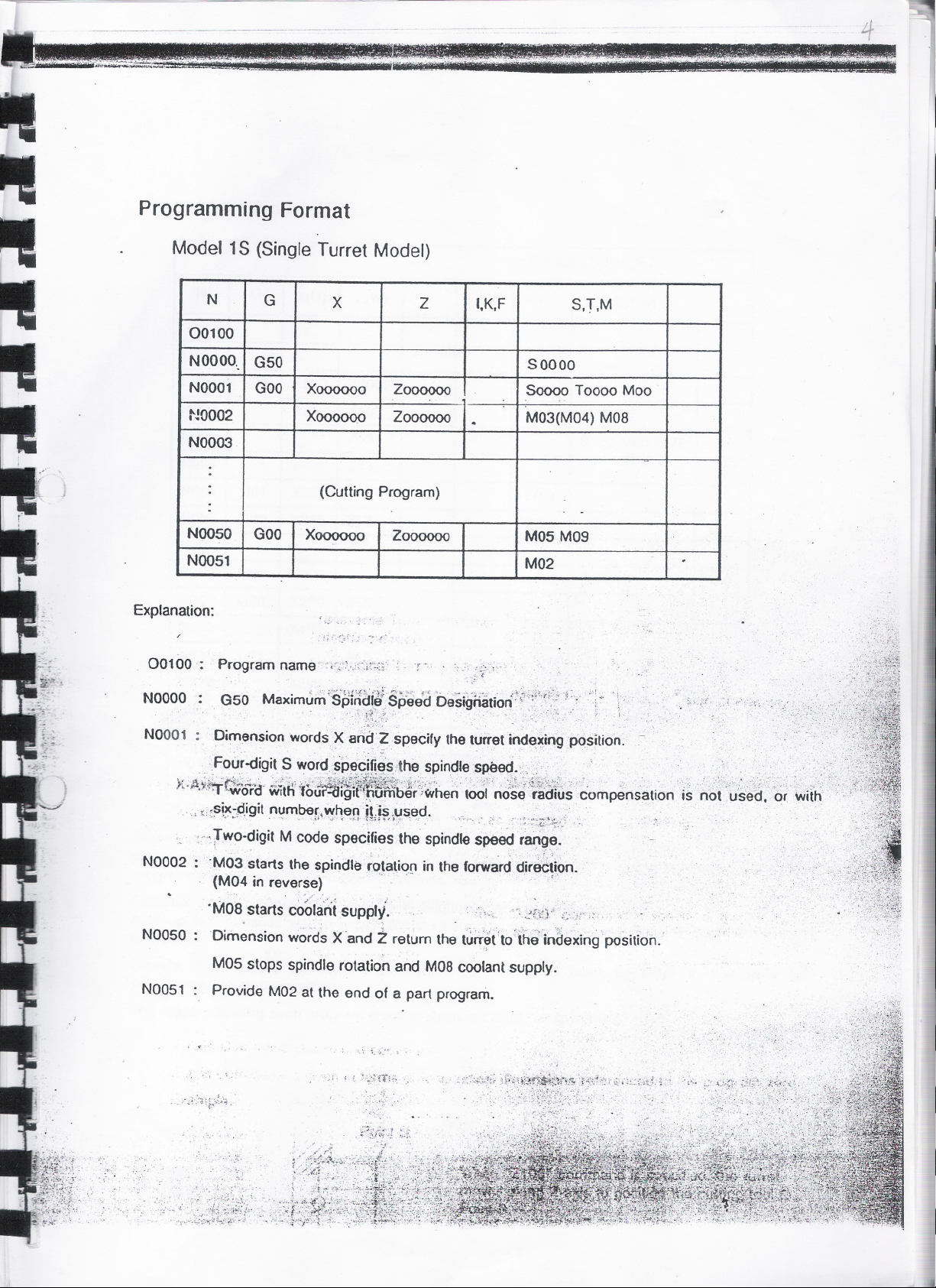
ProgrammingFormat
Model 1S (Single Turret Model)
00100
NOOOO.
NOO01
NOO02
NOO03
N0050 GOO
NOO51
Explanation:
NOOOO
NOO01
N
.
.
.
.
.
.
G
G50
GOO
X
2
Xoooooo 2000000
X()()()()()O
2000000
(Cutting Program)
Xoooooo
200000o
',K,F
S.r,M
S 00 00
Soooo T0000 Moo
. M03(M04) MOB
-
M05M09
M02
~:.'
Dim43nsionwords. X ari~'?specify the turret inde)Cingposition,
.
0
'..
'.,
FOUr-digitSwordspecifi~s;thesPindlespee<fo,>,. . "'." .,' '. ..' '," ,.., :
X~)\.~i,=~6rc3'iiIit~;~fb~f~1~~i;~;~i~heri' ~~I;no~~'~~1h~;~ompensationi~ . no. '~-~t:J: '6r 'wit'h '
, psix-:digit number, when iLis..used. _ , .'.,'
'.~ . '" J~'; 1" .q. ~~i~'.::':' ~". ' . ,:~ '- ... ';':~$..~:~~.
::'-;Two-digitM code speci~ies the spindle Speed r~~o
N0002 : 'M03 starts the spindle r~tatiq~ in the forward dir8c~ipn.
(M~4in rever~;). . ' .
'
O
M
08 t
s a s cooan suppz., . '. ,_.,.,) __., ,. . , "
~
"'
".'
.
rt
t
.; ,,',., ~~,\1'.' .;..'," .
I
N0050 : Dim~nsionword~X'and ~return th~ t~iT~t'to'fhE{inae~ing position.'
M05 stops spindle rotation and MOBcoolant supply.
','
...;
: ",
N0051
'.
Provide M02 at the end of a part program.
: '..
'.'.
,.

.
Program Process Sheet
PROCESS SHEET
.,-.
N
0104
-
N001
-
N002
-
N003
N004
-
NOOS
-
N006
-
N007
-
N008
-
N009
-
,01O
-
..-
, ,(,}0.11
N012
,.NO13 '- ~:;, :':; ,W~;~:1':; .~Z40 $, '
N01l '-;;GOO'( ')(2~o5 t~4~'"
N01S'
G
X(U) Z(W)
GOO
G01
GOO
G01
GOO
.~192
:9°l:!,.t;;~~".:, .1"if~,8:,:,."
'>
X800
X250
X20S
X250
X205
X230 1258
X200,
Z2000
Z100
Z53
-
Z43
I
I Z50
Z40
I
K F
:~~K.~;<i~:"."
.:" r
'!~'~0:', .~-.-.
, r
.,,', ',1 ./J ~I ':i,
S,T,M
M41
S120 M03 M08
FO.3,
FO.25
ro.4
"';;:'.
. ,
. t'~G~.'~:~,-. ,'_'.~-.;". :,..,;. ¥J."i"" t'~P"T""..d':'; ~ - t:~..:. '::,,: "~~~ . };_;." i. __.: _', ~~, ..-,!~~.\~_'-"'~o..~~~';~:;~~"_
, Shown' a~ov~i:,.i1>:~~?,.:~el~-,WPleO! .a program"~'':ocess shee~. It is ~~ti~Wlgwhiph:~e~~!J~~;i~~~:~~\Bf ....
programml~g, InstrUCtions,'compnslng alphabetic and numenc char.ac~~~,,,@~raE9ep,,1.0,;;a'~:~_9.f!.QI~!!.Hft\
':)IF:;~~~f:L
programmin~fscheme:iWith'1hese"instructions,operationsofthe machin~;jirtr'exptess~d:.' y~ >t"'''::~:' :; ':~i;;:"
Ecicn'line of the~
Agr'oup of commaf\ds .wJi~tef!in o.ne,line,is referred to.as a -block- and it-describes one machine,.'.' .
operation. . , ., ;
T.' '., . " ---"" .. _' ~ ~. .~:r ~.~. '. ~ . I. :; :
Usually, '(he machine executes, the programmed commands block by block in the order as
programmed to produce a part.
The steps preparing such program process sheet is called .programming~.
p
. . . _ ,',' .' , _,_'. :,.-:,;~, ,- .-. ," ~:_::,.,:..:():::-~~~ .-:.'\:~_-~~~~:':::.r~~:i'rj~
rocess'~t1eet ~tarts with'
, . _: '.. ',,"..~: ~.t~.- ..".' " . . : \.', " '. . "\.' . - ~
.'
. .' . :",.,;..,,,\
S
'.' uencatNumber :{N''Wora)
eq
:,~t;KIn"
,--', -:?;,;,;~.:, """;}~~?;;f~~
I~'
II
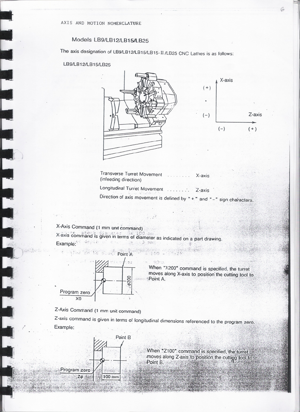
AXIS AND MOTION NOMENCLATURE
.
Models LB9/LB121LB1S1lB25
The axis designation of LB91l812/LB151lB 15-IIIL825 CNC Lathes is as follows:
LB91l812/LB 151lB25
X-axis
(+ )
(-)
(-)
Transverse Turret Movement
(infeeding direction)
. . . . . . . .
X-axis
Z-axis
(+ )
Z~axis
,'.
.'
-.t-:.;.
LongitudinalTurret ~ovement
". . .
Direction of axis movement is defined by .. +" and ..-" sign
;1
. >
X-Axis Command (1 mm unit ~OfT!rr~an~).; :' ;, i;. . "
. ~ f;: t1 '" '{'p,. ~ '}1 i";- _ ':;, or C~"'. :';';,;' 'i~/D...:._~i-':-t;~... . ..:_.:':/:." '_"",. ',_. ;._:
X-axis command'is given'iriierms'Ofdiameter as indicatedon apart drawing.
.
E
. t. '. '1+..:, 1', . . '..0; :> :..::,.:' ".
I
xamp e:' . ,
Program zero
----
xo
Z-Axis Command (1 mm unit command)
/
Z-axis command is given in terms of longitudinal dimensions referenc~d to the progra"rt~,'3.t9;}_c;;:i'-';'-i;;-:
Example:
. ." '-;;J;~:~(~..{i~~:::~~~:~~:..~""'~',;[o"j..:_\.-~.~..
~=.~ ,..,-~~
11II'
_~.r..,~'~~",~, ~ ..
1
III
--
.'
181
HOWTO PROGRAM CUTTING CONDITION
Basically, the cutting conditions such as SPINDLE SPEED, FEEDRATE, and
DEPTH OF CUT use on a CNC Lathe can be determined in the same manner as
in the turning operation on a co~ventionallathe.
All the programmer has to do is to convert the
conditions into the coded, digital form as -per
and to register thes~ numerical information on
a) SPINDLE SPEED is specified wit~ a maximum 4-d~gits S code.
e.g If a spindle speed
m/min is required,
respectively.
b) FEEDRATE is specified with a maximum of 5-digits in Metric system
of 350 rpm or constant cutting speed of 120
it can be program as G97 S350 or G96 5120
pre-determined cutting
the data input format
the process sheet.
F code.
e.g If a feedrate of 0.35 mm/rev is required, it can be programmed
as G95 FO.35.
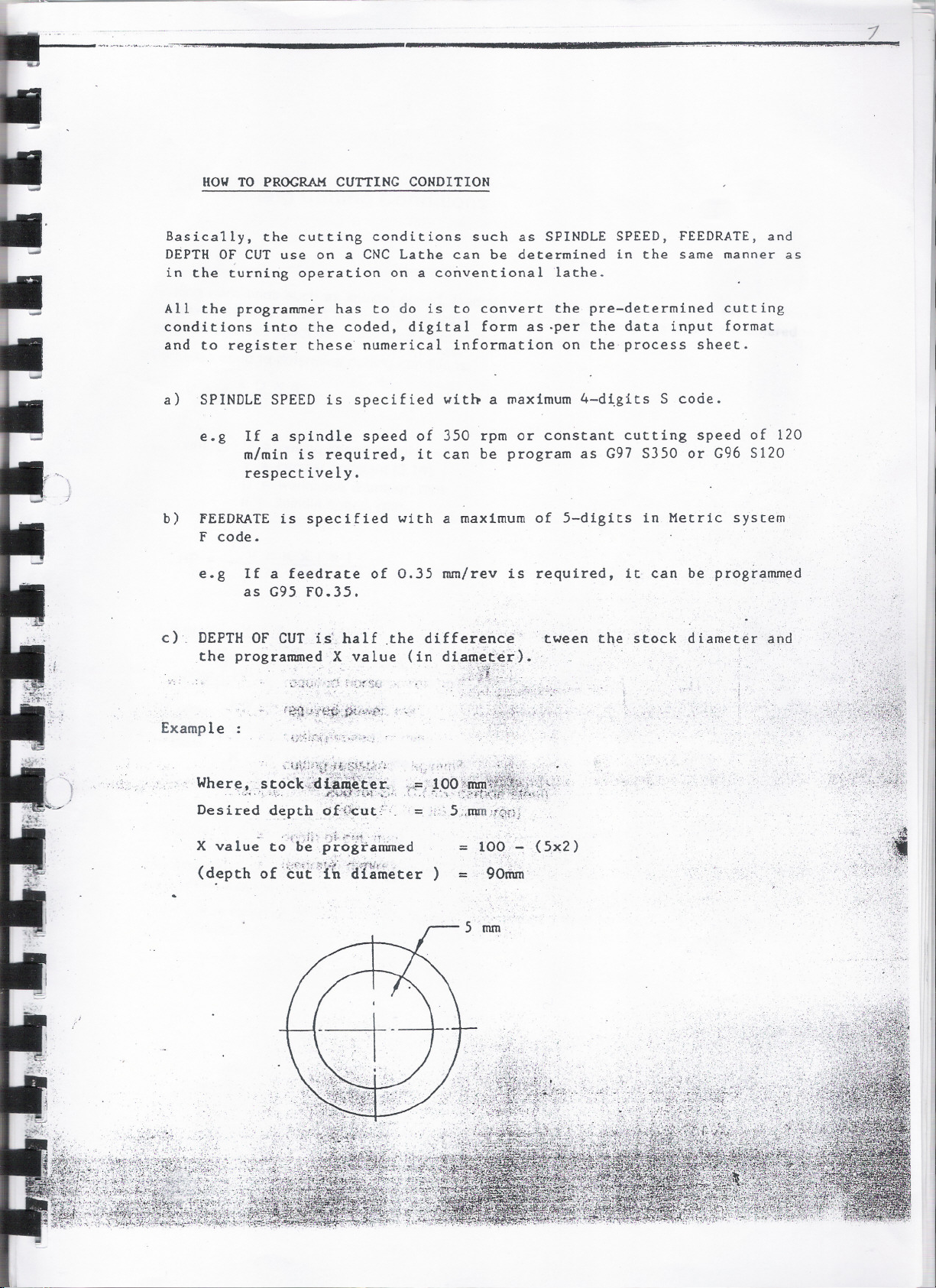
C),
Example
Where, 'st6ck-4;ditnt~t~ei..
Des iredd~pth ()t(~ut,~i. ='i~5 ;,mm 't.~nj
X value to oePEogrammed
(depth of ;~m:~{~ '~a7~ri;eter)
. ,,~uV.r~~{~'Jt..~f~~~f?~.~'~;:;~-:. r~p:;:J:
. ",~:"~;". ;--\~~. ,... ~~J:~;).r:.;;:.!.',
.:.:.. .',.f'''-,r. ;-..;i,;~',--~.."r . .
= 100 ~ (5x2)
=
90tfun'
,.....
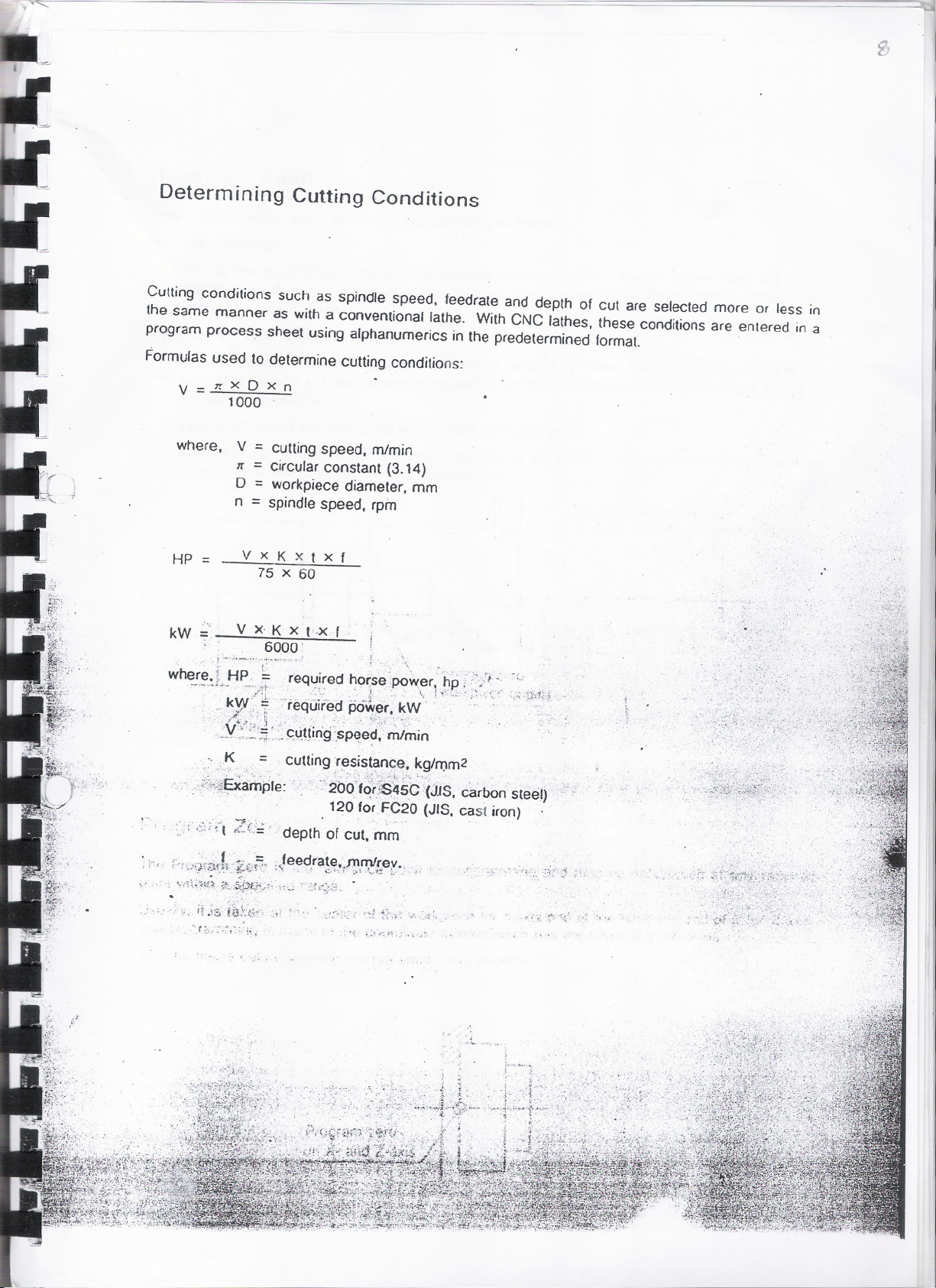
Determining Cutting Conditions
Cutting conditions such as spindle speed, feedrate and depth of cut are selected more or less in
the same manner as witha conventional lathe. WithCNC lathes, these conditionsare entered in a
program process sheet using alphanumerics in the predetermined format. '
Formulas used to determine cutting conditions:
V=1rXDxn
where, V = cuttingspeed, m/min
I
1000
rr =circular constant (3.14)
o =workpiece diameter, mm
n =spindle speed, rpin
HP =
kW
. . j -"'!"-~" ~... . r ". _\ .
~here, ~ HP, ~ required hor:sepo~er, ~p e/i'.:" ~'.<,.
VXKxtXf
7S x 60
, .
V xJs ~_!'-x
6000'
, , ,
'-'-":'~~i;.;t:'ieq~~~~?, ~O~!~'.~~\ 1'co' "'" ' ',Q'I~J,
.:~Y:.:~~:'~>._~~mrig'.s~ed,' m/min
~."I< =, cutting :r~sis~~nce~ ~.g/t1Jm2, ,
". ...: :1.:',,,.~ 1',0i-: .' ...
,,~~;;.1iEXartiple:' "26d'fO'r~45C :'CJJS,carbon steel)'
"
,', 120 for FC20 (JIS,
,~:dt ZL;' depth of cut, i'nm
cast iron)
';.,
. .,'
..
"
,'~
......
,~,
- -,'
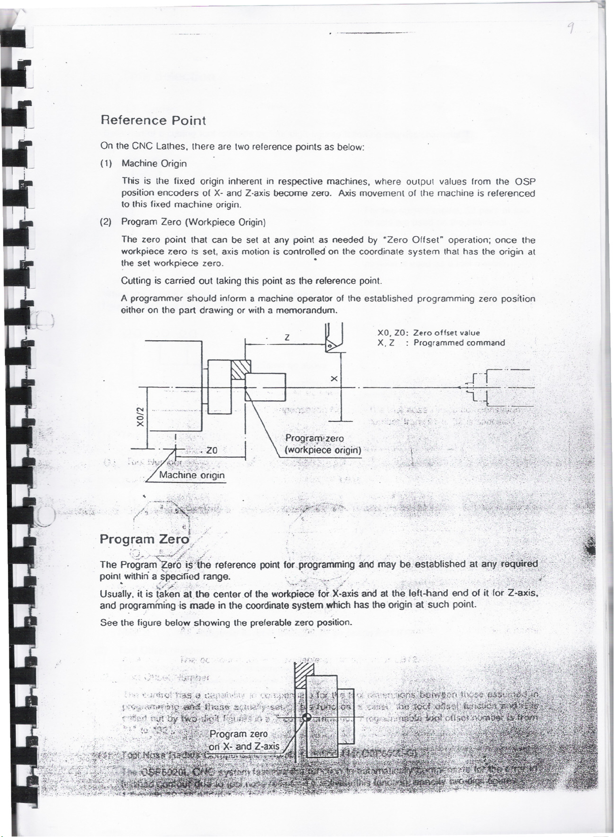
Reference Point
On the CNC Lathes. there are two reference points as below:
(1) Machine Origin
This is the fixed origin inherent in respective machines. where output values from the ~SP
position encoders of X- and Z-axis become zero. Axis movement of the machine is referenced
to this fixed machine origin. .
(2) Program Zero (Workpiece Origin)
The zero point that can be set at any point as needed by "Zero Offset" operation; once the
workpiece zero rs set. axis motion is controlled' on the coordinate system that has the origin at
the set workpiece zero.
Cutting is carried out taking this point as the reference point.
.
A programmer should inform a machine operator of the established programming zero position
either on the part drawing or with a memorandum.
Z
x
.~.. ~..
N
.......
a
X
. .
.\J".
XO.Zo: Zero offset value
X.Z : Programmedcommand
'~."~.
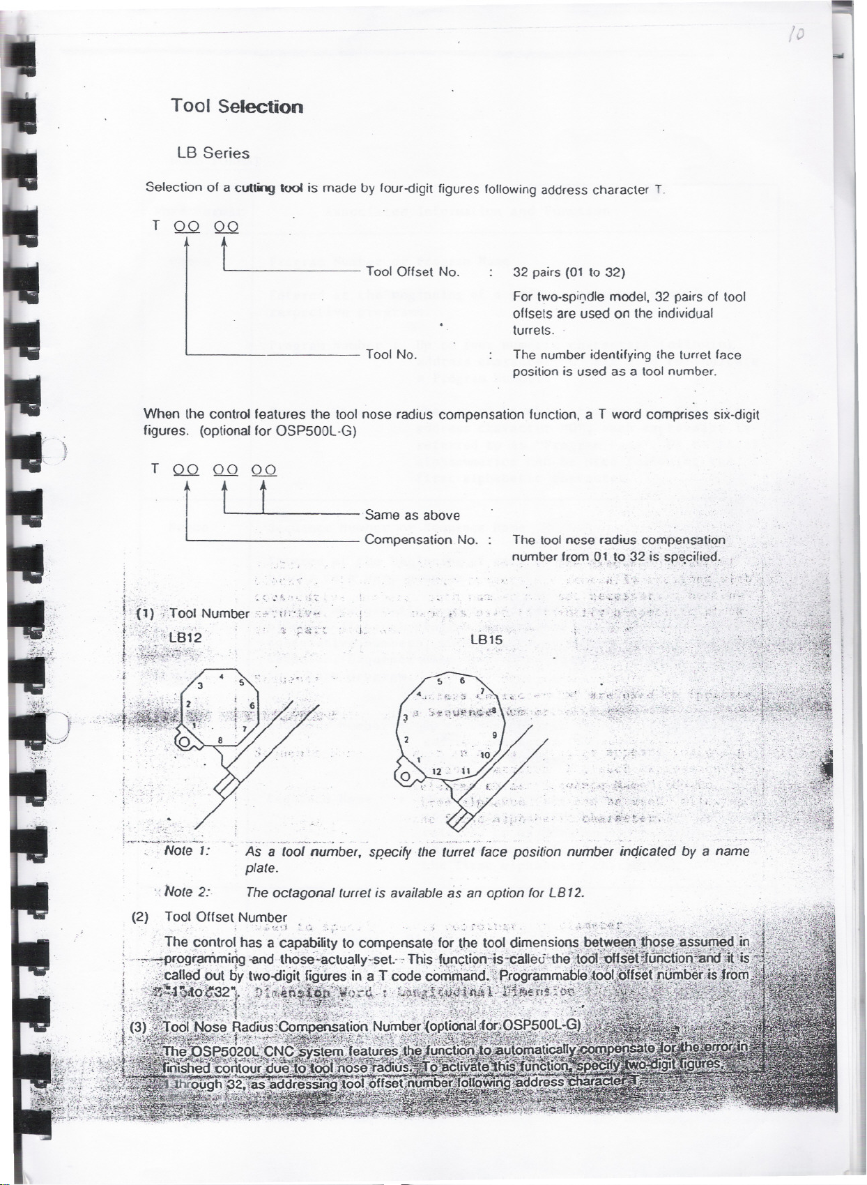
Tool Selection
LB Series
Selection of a cutting 1001is made by four-digit figures followingaddress character T,
T 00 QQ
,
v
t
Tool Offset No.
32 pairs (01 to 32)
For two-spil)dle model, 32 pairs of tool
offsets are used on the individual
turrets.
ToolNo.
The number identifying ihe turret face
position is used as a tool number.
When the control features the toolnose radius compensation function,a T word comprises she-digit
figures. (optionalfor OSP500L-G)
T Q.Q 00 00
tU
(
i
.t .
FC;) :"ToolNumber
, '
r:~.::,;:;~~:;~~~}~. '
. . >~.. . ",,~,., .
.
!
. '~t!.::~."~~~~._t"7j. - -~..'
I
"..~. .. I!.~. . t.. )....
..-~ ~
. Same as above
Compensation No.
lB15
The toolnose radius compensation .
number fI:o.mo."-,o 32 is sp~cified. ;
.: <:.-~..;-;..~'
~ , .; '~j. ,":.">'~'S.<~.'
';::.". ~~.'
\;' 3~\~".:t'\~.f~",~ ''''~''
,tf~~$.~~:~_i._'-,:", .
-~''::-
;
t,
o ~<-.- .
,
"
(2)
- -.. -. .,--, ~--'. - ~ -. .'.,.~ ..." . -.' 'p .-
As a tool number, sp'ecifythe turret (ace position number inc!icatedby a name
plate.
, Note 2:, The octagonal turret is available as an option (or LB 12.
Tool Offset Number
. ~. ..~ ~1. ~ .....
, .
. '.' -. .::"". .-'{
-::to":~." ,to
. ~",'~. .
..~
.
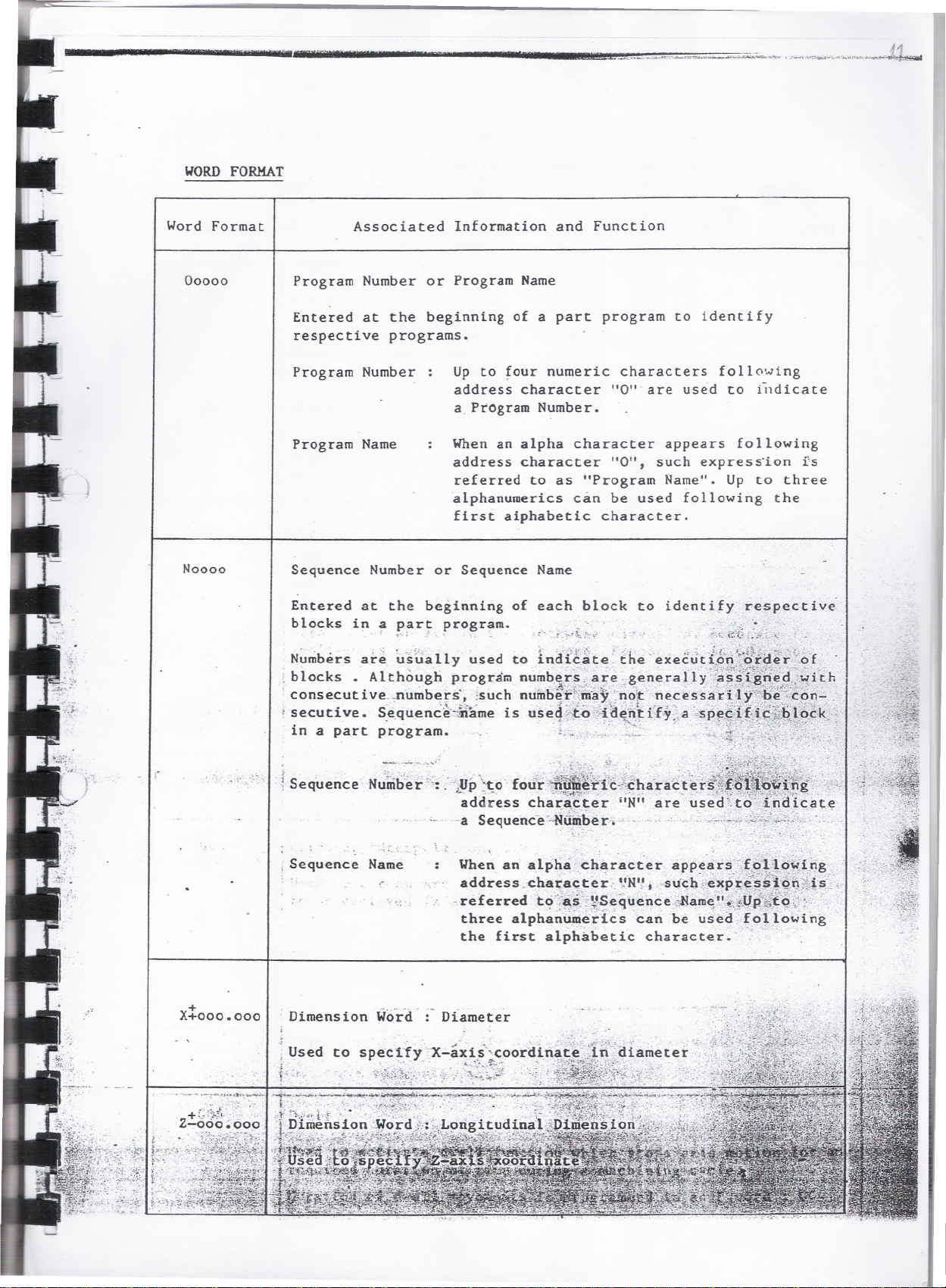
WORD FORMAT
Word Format
00000
Noooo
Associated Information and Function
Program Number or Program Name
Entered at the beginning of a part program to identify
respective programs.
Program Number Up to four numeric characters following
address character "0'" are used to illdicate
a.Program Number.
Program Name
When an alpha character appears following
address character "0", such express'ion is
referred to as "Program Name". Up to three
alphanumerics can be used following the
first aiphabetic character.
Sequence Number or Sequence Name
Entered at the beginning of each block to identify respective
blocksin a p~r~ program. d...; -: ';.'.;,:~,. '.
~"" ". ~ :-".'1:,
~"" ~ '.' /'"..1..C'1...~ ~~;'\-.1..:"
X:::ooo.ooo
N~mbers .ar~ \£~ta lly used to Indg~te ;'tbe'exe~Jd::g~:;::gt~~?~:~.~ .
; blocks. Although program numb.e~~..a~fi!~.general.1Y"a.;>.§,{.gI1.e~,t~lth
. consecut i ve. .,numbers'~ ;such numbe.i;'!::.m~y, :1J9\t"necessarlJ.y-"r!>,;~'~,C~ri-': .
. '_'~." ,.",';~ _ ," " '., '. . .'.., .,:', '...,'~..~rv7.t, ..
-.-;. ~ _ .:1 ",' _,,~ :..,.'(. :"~'''-..:Z, ,"_ '. , ' ''''''":j .' ~...'t '~.-J: ~.,." ',:;. :
'secutive. S.e.quence'-iiame is use~;'.~~s:1-}t.~~~i:fy.;.a.'sPf~~;\}~~~J,ec.k>,
in a part program. !.~..",' '''---~~':~;,<:~'f;~';;':':~';:;'
!Sequence N.;!;iil~~:;:.'i!Jp~~" fou'hiitl~'<i.,1a...{t~~_i',
address chaE:~F,ter"N" a:reused?tO:c;:~Nlicat~
.a Sequence"-N~m!:>er'," . _.,..;:.~.:J:/':./~,~'_
. . -,.~'..
,Sequence Name
When an alpha ch~r~cter appears'.~i£,~i.~l.~~1.#g..
,..:::::::t~:1#~~~;~~ij:~~c':;~~~:;~;1:il.~~t.~~!.$.:-
three alphan~.erics can be used.fol,lowing
the first alph~betic character. "
Dimension Word' :- Diameter
. .
,
,.
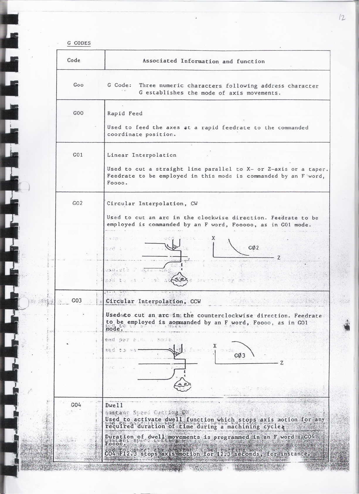
G CODES
{2-
Code
Goo
G Code: Three numeric characters following address character
Associated Information and function
G establishes the mode of axis movements.
GOO
Rapid Feed
Used to feed the axes .t a rapid feedrate to the commanded
coordinate position.
GOI
Linear Interpolation
Used to cut
Feedrate to
a straight line parallel to X- or Z-axis or a taper.
be employed in this mode is commanded by an F'word,
Foooo.
G02 rCircular Interpolation, CW
Used to cut an arc in the clockwise direction. Feearate to be
employed is commanded by an F word, Fooooo, as in GOI mode.
'x
.~'f~
t,
i
,
G03
-or,....~_._._._..
""-.
,,~.-~.-\"'" '-'''-..~:':,:~~
~L~li0:11_r.. 'I~~_~':,e.~!l~~l_'_~~,~
.Used;l~O"cut,an,'arcc-;i!.mthecounterclockwise direction. Fe~drate,
_t?.-ibe~empl,oye,d_
.........-
~OQe~.'1~..~.:.' .._ .. ,.'''':~_:=,,:''_" ,"
,.
G04
is ,~_0!J!4~nded by an F}~ord, F()ooo. as inGOI
. t
1 :0
.-.- .. ".
z
z
'..
'"
/3
1
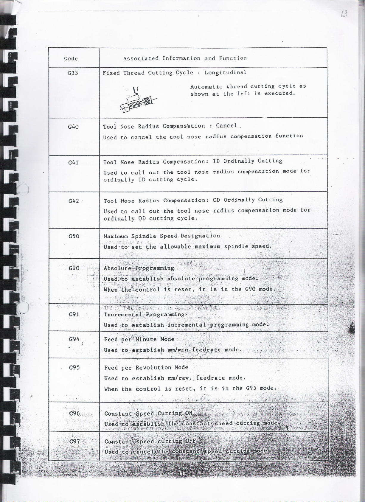
Code
G33
G40
G41
G42
Associated Information and Function
Fi~ed Thread Cutting Cycle : Longitudinal
Automatic thread cutting cycle as
shown at the left is executed.
Tool Nose Radius Compens~tion : Cancel.
Used to cancel the tool nose radius compensation function
Tool Nose Radius Compensation: ID Ordinally Cutting
Used to callout the tool nose radius compensation mode for
ordi~ally 10 cutting cycle.
Tool Nose Radius Compensation: 00 Ordinally Cutting
Used to callout the tool nose radius compensation mode for
ordinally 00 cutting cycle.
G50 I Maximum Spindle Speed.Designation
:Us-ed'::t'~::;'~:t'~he 'allowable maximum spindle spe,~d.
G90 ~.
\
G91
G94
. l
G95
~':'5({J,.~:-;?~.~~:~~"~~:~k~~~. 5~-~;5 ~{~::-:.7?1~:?-~3:~~:':}r~7i\,*:~~~~f1,
IncreriieJl.i:aJ.d't~QgramiUing ..:',' ..
_ ..-'.'.:'~>~:'_;'t-\..~..:;.. ;;". ,~,; ,.~..:<-'.~:.~.~J~::...:t::.};. . ":..~",.
Us.ed ,t~es tabUsh increm~t\.t~l~Gpr<?gr~umil~ngD.1<>d~{
. . oJ.'~p'~.~'~""=...f'(-, .. ,"?~,,_,'l~,--~~.;~..1f~L.~-:i.~',.' . "-- ""~'(-:":~"'1::.1:~'-
Feed p~~~~:;¥n~~e- M~~e" ':;,; ;,~l:ii~r:
;Usedto:~
~~ ~ab 11 sp~~~ita~~;!!i~~~:~fJ~l!Iode ~
Feed per Revolution Mode
Used to establish mm/reY~lfeedrate mode.
When the control is reset, it is' in the G95 mode.
."..'.;...,".~" . . .'.
.-
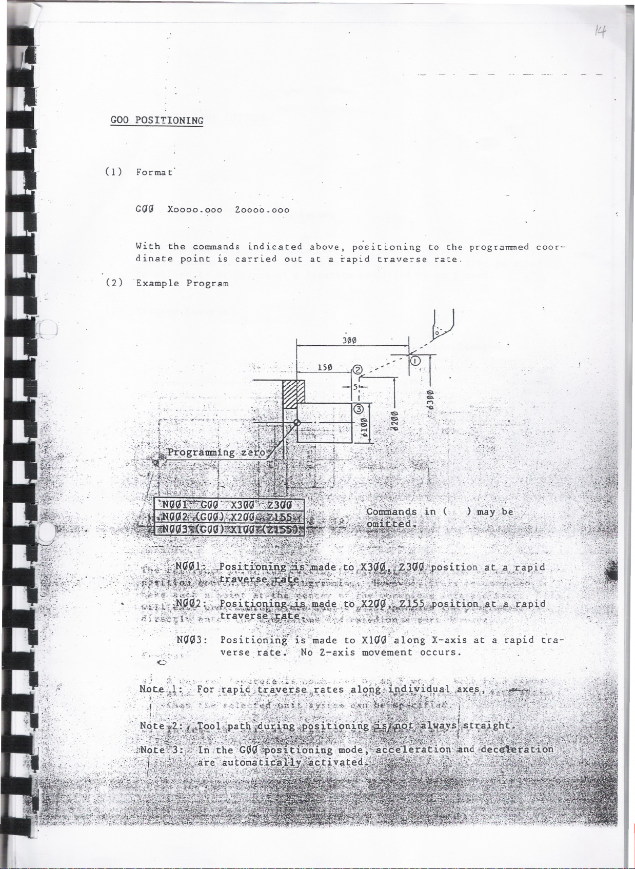
GOO POSITIONING
( 1 ) Forma t'
Xoooo.ooo Zoooo.ooo
I .
....
With the commands indicated
dinate point is carried out
(2) .Example Program
above. positioning
at a rapid traverse
300
to the programmed
rate.
coor-
.-.
;;)'. r
Position:ing'i"s\made to .Xl(N-along X-axis ata rapid tra-
verse: rate.:. . ,No Z-axis mov.ement occurs.
. ._r...,,...),;..,.,'~'' : , .. . ~"" .'
, ...;, ,:.". . ,'-.
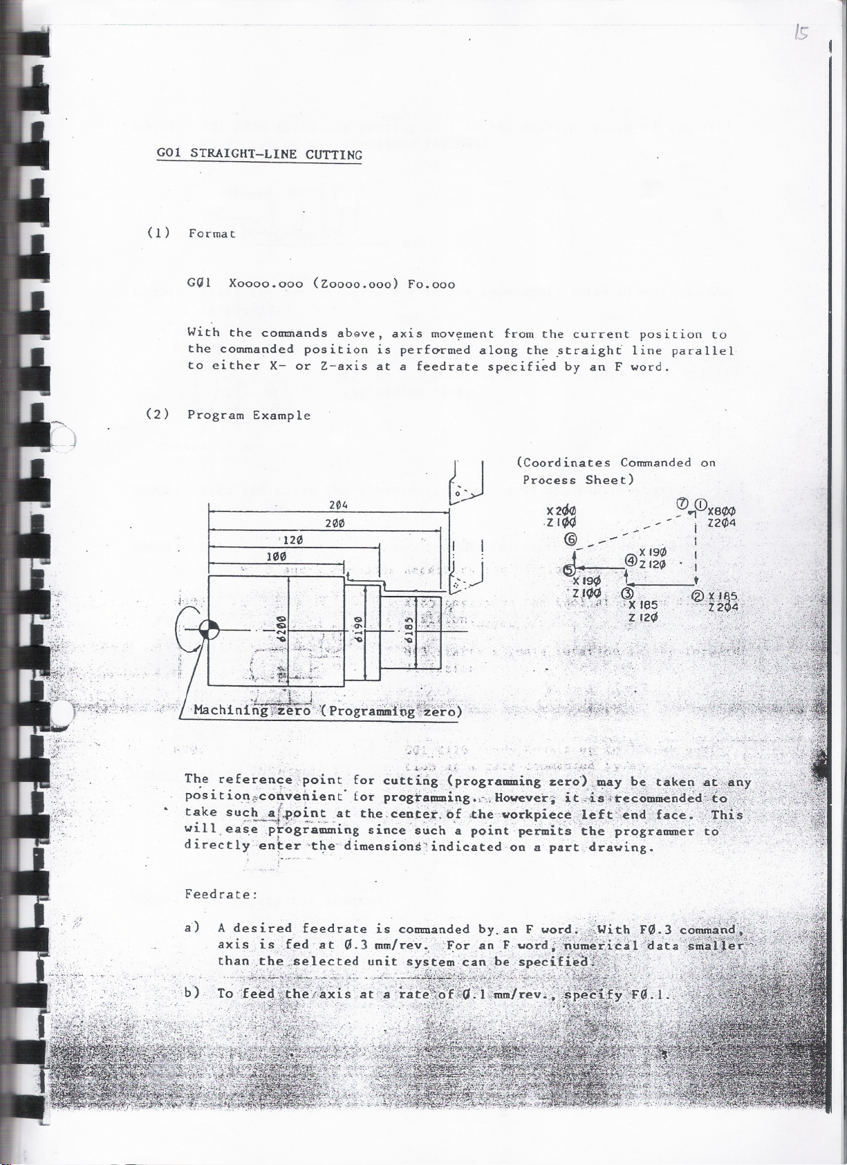
GOl STRAIGHT-LINE CUTTING
(1) Format
GQl Xoooo.ooo (Zoooo.ooo) Fo.ooo
With the commands abGve, axis mov~ment from the current position to
the commanded position is perf~rmed along the ~traight line parallel
to either X- or Z-axis at a feedrate specified by an F wordo
(2) Program Example
/s
; ._,
(Coordinates Commanded on
Process Sheet)
100
.' '$
-....
': "0
...-6:-f':~;'
! ; . .
, 120
....
..
$
i;~;d~r;)1;';
204
200
~.~t" ;",.,:>.l~.:.j
<5>
'0-
. I
X2~ ([) (!)X8/f4
ItA -~
.zIOff ;._ - - i Z24>4
@_-- - . I
:.;' '
~- . X194> I
..
,.,.,.. .?z 12~ 0,
-)(j9~" , t.
..:!/~.;'.<:fi. .(zt~)
,.:!, ';'
, '~:,,"Z !2~' >:',.~;.;
X!e5
" ...,
Z2
"5..'>
"'.-
a
..\..-:,.~,
'"
Feedrate:
;':b) ,
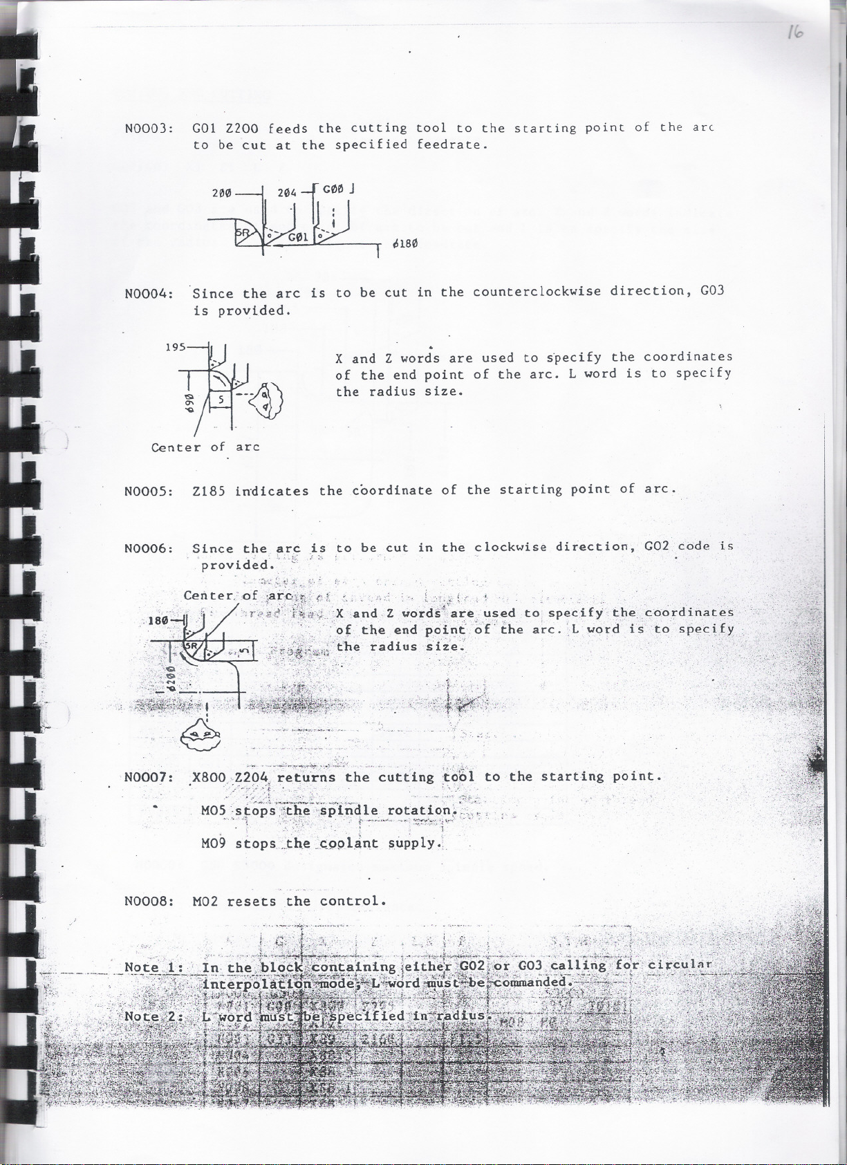
NOOO): G01 2200 feeds the cutting tool to the starting point of the arc
to be cut at the specified feedrate.
N0004: Since the arc is to be cut in the counterclockwise direction, GO)
is provided.
X and 2 words are used to ~pecify the coordinates
of the end point of the arc. L word is to specify
the radius she.
. ~.
Center of arc
N0005: 2185 in~icates the coordinate of the starting point of arc.
N0006: Since the. ~r~ .is to be cut in the clockwise direction, G02 code is
. provided."'~ J.~
center,:'of'~~f~~;-:-~1~~.~.."': :.-,:."i,.' .
,.,u:~ :~~~,;;;:t~;~~~:~~::~:t;1r;r~~~1~e t:~:~~~l~~t~h~. C~:t:~;~:~;
.~~; ., ,'\(':tf1'",' , '
-
- -. ., , , '-..
; .__~-..~~ ~,.,\..::;';~~~.._._~._no','.'
-."' -.: f~~"~-"~'~'--; ~~;;:'::;:f~'\ ~~...' .", . -
N0007:
.~
.X80~.<~2q~~ retu'rns the cutting :to~l to the starting point.
.~'/~:';:'~~:;!'..\; ~~':.. _..' _ '. . --:-..:~--<~t~.
M05 'stops'::1,th~-;;spinalerotation~ >.:';~ .
~'. '.; :'j:_~~?~"-:-
M09 stops.~.th.~ _~9pl~nt ~upply .;.
.;--L
N0008: M02 resets the control.
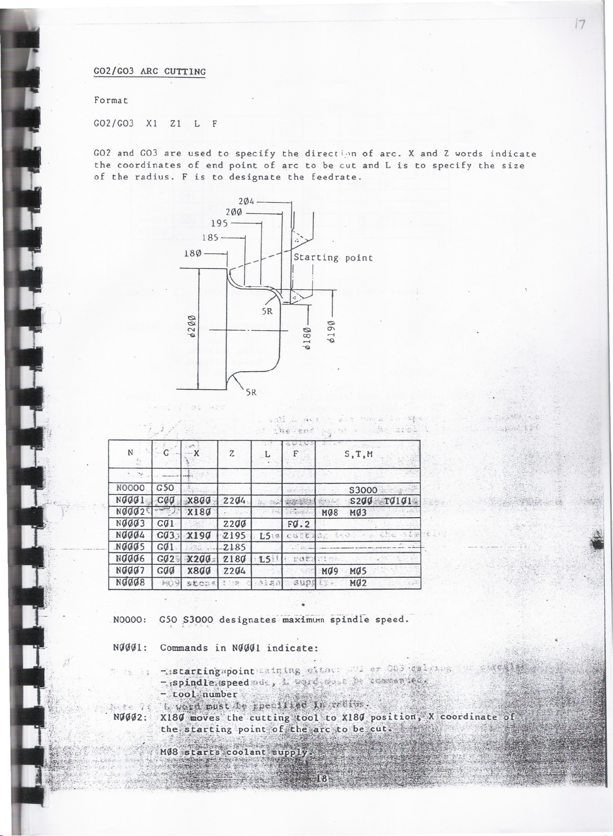
G02/G03 ARC CUTTING
Format
G02!G03
Xl 21
L F
G02 and G03 are used to specify the directi:'n of arc. X and Z words indicate
the coordinates of .end point of arc to be cut and L is to specify the size
of the radius. F is to designate the feedrate.
point
5R
N
'G -.
. ....$
..-.-..-
NOOOO G50
NOGGLeo .c,,
N(,)G(,)2-
NIJG/J3G1J1'
NOGIJ4 GO)) X19/J
, .N1J1J1J5 GIJI. . ..--,.:.... '.. Zl-85
1/J1J1J6
NOGIJ7
N(,J008
Vl.'
GQ2S
GIJG XSO/)
,',.... ..
--X Z
\,.
+
'., ....
'XIS/J'
:2(J1J:>
J9
8GG
"
t.-c ::.
Z204.
Z20/J FO .' 2
'195
Z18/J
Z204
..< .: . )ii1
. L5\
'L5:U
.L
. .
:': -:r;':'
,..",.:.I..
F:
..... ."...".
.;\;.;it:,
.';':;1r£.i::'
c,;t'i
. ..,'-
-!' t:"t1t">
'..&\iPJ
NOIJ/)I: Commands in NO/)lJl indicate:
.0;. ..
-
-. .
S,T,M .
53000 )-" .,;.:,):.
ij;'.'..::
,s2QIJi.$fkTQ 1<1 14
M08 MG3
..
-:i . .:.'.::
.----------.----..::- _...:...
.'('..
...'
M09 .M1J5
..
!:-;-
MIJ2
,_:,- '..-'
-OJ."
.~j
-,
-- ". .
'.

I
N I
NOOOO
N<lGI11 GI1I1
N
NI1<lG3
NGGG4 X2<lG
NI111G5 GI1G x811G .Z2114
N
G I x I z
I [,K
F
G50 S300
X8GG Z2<l4 S211G
2
6
GGI
Xl85
Z211G
ZIGG
FI1.5
. .
NOOOO:
N<1<1<l1 : Commands in NG<1<11 inrlirate:
N<1<1<12:
G50 S3000 designates maximum spindle speed.
starting point
spindle speed
tool number
Xl85 positions the tool at 18S.mm
diameter position.
S,T,M
MQ8
MI19 MGS
MI12
MG3
TI11111
HG3 ,starts, spi~dle ,rotation in. the'.for-
wa~ci'direcCio'o~,
~~~ffI; ..;;~~~.;t;;!;~~L~3~i~~i,~~.~?5~~f~~\~
"'-~. j
, " " .....
~J. " . .'"
~~. S :3'.~
':f;;~42:~K:. =!'~.,-:.~~~:~:~~'; J~'., ~:;:~.~
...1N<l<1Gt.:~.("""";" j ft., {; ',;i'1;" . ·
,'N Y!.C'i".!? ;;Q~:e.:-r~;~~
£eedrate 'iri:PI1l.-mode'
'.
'-0';"."

.
G04 DWELL TIME
With G04, the tool is stopped for a designated period. The numerals are
after F word indicate the unit in seconds.
Format: G04 F... .
A dwell for 2.5.seconds.
NIOOO G04 F2.5
Note:
GQ4 function is effective only for the block commanded.
G33 THREAD CUTTING (STRAIGHT 1. CONSTANT LEAD THREAD
(1) Format.
GOO
G33
Thread cutting is performed in G33 mode.
Xoooo.ooo
Xoooo.ooo
Xoooo.ooo
Xoooo.ooo
X: Diarneter,;.ofeach thread cuttiI!g:cycle;
Z: :End'point of thread in longitudinal direction.
F: 'Thr~ad";lJad ;;'cj. j,.. ,
'" ;": ~:::::;;. . ",. "~'" .
Zoooo.ooo
Zoooo.ooo
Foo.ooo
> .:...:;. .:~~.~.- .i:._'~...
.( -
.- ...
d:.t'e8..d
.; !~\,:.-- " \ .:.,:
.. ~ I'.~.~ .~t..
..~ ... i. ...,.
N G
t.. .
,'/... 0
lStardng~"~o1nt 'of
c~tt1n~;;c;ycle
0-
x
z
I,K
F
S,T,M

-- --------.
GO! TAPER CUTTING
Format
(1)
.
GtJl Xoooo.ooo
The same commands as straight-line cutting. are used for cutting a
taper.
(2) Example Program
Zoooo.ooo
100
Fo.ooo
<Coord inates

N I
G
X Z
[,K
F
S,T,H
GSO 53000
GGG X8GG Z2G4
Xl8S
Zl2G FCI.s
HG3
HG8
52C1 TGIGI
ZlClG
[ )
z2C14 I I I HG5 HQ9
HG2
Commands in ( ), where the same command as provided in the
previous block is to be entered, can be omitted.
NOOOO:
NClG01
..
.)+t; ,..,~. :.:
~t ::'~/',t~.;:.~.'~~~~~~~~.'ri.~~r..
NaaG3:
G50 53000 designates maximum spindle speed.
Dimension words X and Z indicate the turret indexing position.
Sand T commands
M,
. .
necessary for cutting ate ente~ed~
. .
n. . .
'v ."._~. .'
Has starts.coolant supply.
..

NCHHJ4 : GOI X190 feeds X-axis up to 19~ mm
diameter position at 0.5 mm/rev. which is
120-I
specified in the preceding block to finish
the shoulder.
NIJ"Q5:
GQQ X8QQ Z21J4 returns
M"5 stops spindle
MIJ9 ~tops coola~i supply.
NG01J8: MIJ2
.' ~~~ ~$'~~-~~-l: .'.
100 -j
resets the control.
. ---". ._-~~ ~'- -'"
GQI ZIGQ feeds Z-axis up to IQQ mm POSi-
tion at Q.5 mm/rev.
Gal X2GG feeds, X-axis up
diameter positio;; at Q.5
to 2GQ mm
mm/rev. to
the shoulder.
the
s ta r ~,i,~8;;!"~j~it~
- '
ro'tat ion.
-
the cu t.t ing,.to?,l to
£ ~...~':;;;.;'!-~:..-l-.~.
t
.'
finish
:~. .~:-;.~
",.
"
......
"

GSO SETTING OF MAXIMUM SPINDLE SPEED
If the maximum spindle speed is specified with a ~ digit 5 value preceded
by G50 code (G50 5 ), the actual spindle speed will not exceed the
maximum RPM, .specified even when the programmed S value calls for the speed
exceeding the maximum rpm of that range.
Format
N0002: .G50 53000
The actual spindle speed will not exceed 30QO rpm if the speed is specified
as $4000 by mistake.
G50 command should be written in an individual block by itself.
G41 & G42 TOOL NOSE RADIUS COMPENSATION
G4.1
G4.2
Z2 Z1
. ~
,
,
ZI4 Z;3 :
I I I ~
I , I I
i _L
:
V
-1 , I
I I I
I
I I I
l) I
62
'\
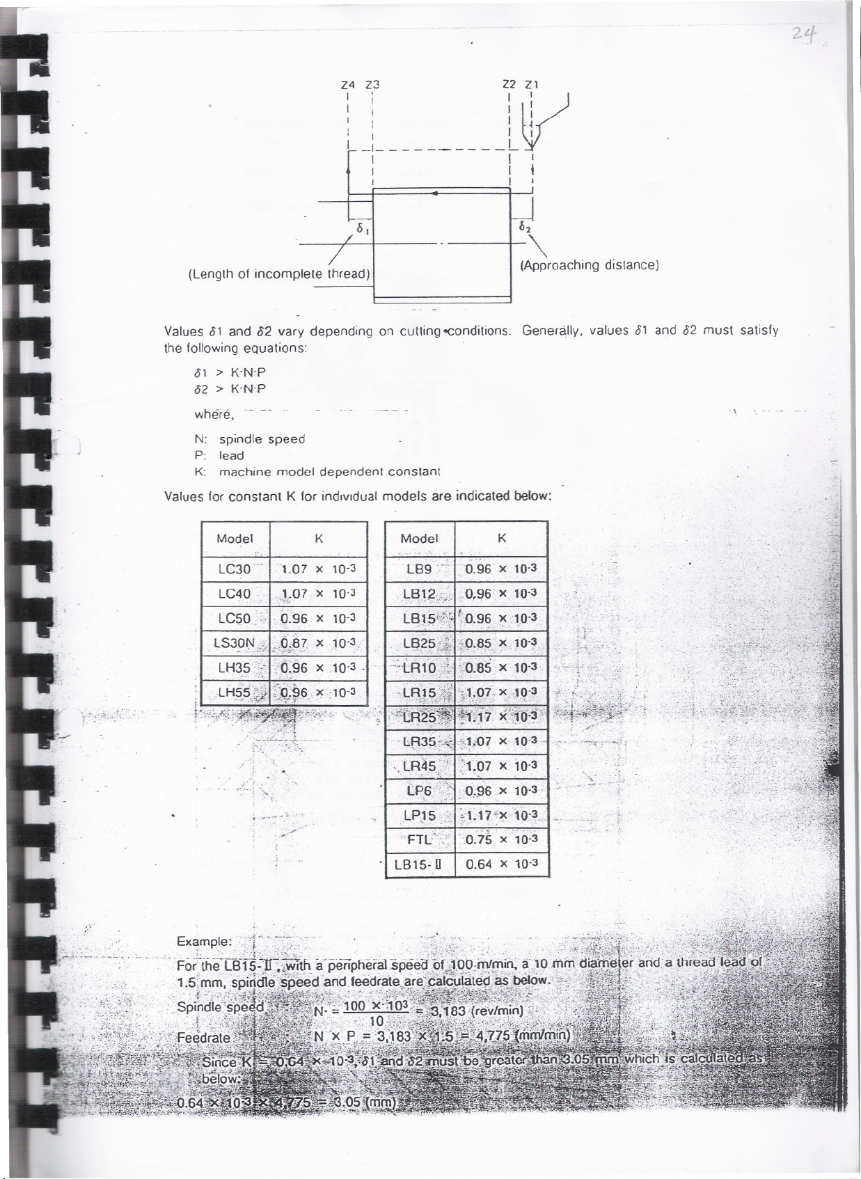
(Lengthof incomplete thread)
Values. 81 and 82 vary depending on cutting-conditions. Generally, values 81 and 82 must satisfy
the followingequations: .
81 > K-N'P
82 > K'N'P
where. .- --
N: spindle speed
P: lead
K: machine model dependent constant
Values for constant K for individual models are indicated below:
(Approaching distance)
".
Model 1
K
-
LC30 _. '1.07 x 10⁻³
LC40
. LC50.:: . 9.'96 x 10-3
LS30N)~ j),87. x j 0'3.'
LH35 ,'0,96 x .10.3.
.LH55~~ ~::O;96 x; 10.3
.., ',¥"""..,.. .
_J.;;07x 10.3
~ '., .. 'Y"~""'~' .
;. '"';0
.,", . -' :.,: ./: ..~. ....
'.
. ,..,-, -"
..
Model
. lB9 ~"L "D.96 x 10-3
.lB12.;.;.",,;,0,96 x 10.3
",:" -; .., , .' .
LBJ~";;)
'l.A3St~ ,~l;{)7 x 10.3 -I,',
. . LA4S'): ":-1"07 x 10-3
'-. '.-:~...:.',~:,'.;,'- '''.;..!.~ , .
tp6'i<~ 'O~96x 10.3-
lPJ5 .': ~
"FTl~';'.': "0.75 x ',023
':~'O.96 x .'1.0'3
,
. . . .
". . - .
. . ..., -. -,
'
'\. :,...:'..;- '.. ...
. .
K
.;1~17~~"0-3...
.
0.64 X 10⁻³
.}L-;
..

N(.J(J8: GGG x8/J'/J' Z2(1S returns the cutting tool to the startIng !"'lllt <II
a rapid traverse rate.
MGS stops spindle rotation.
Naa9: M02 resets the control.
X Words in Thread Cuttin~cle
Note I: Number of infe~ds ~n thread cutting cycle should
bp Sp.(p.clt'd
a~~o~ding to"material to be cut, t~read l~ad, etc.
Note
~ _. ...' ~ . -.~.""._- '" '. ',. ,.- ,~._~...;.,..,:... .' ." " :
. . .. - .
CUTTING CYCLE.
PRECAUTIONSi~FoR-; PRoGRAHKINC;1tHR.EAi>,jCUTTING CYCLES
..",,'.~:',~~~~'r-:.§~~~.>o:.. ~:~~j~!~~J;L~'~':"~~~_?'T-:1S.t.:!,~j.,:~.;L:'...
Observe.-:~he;(opowing p~h1fs~$h~rit progr8'mritJng'jf;4r~a4~utt: ing.
.,u;\,;.;;~*!~"i+it~;;, .f"i~i1~ft'r~'1':'~\ '~.;;:'\??;y(~~~'f;~~;~J;.~,~.;..
1) Spindle :Spe'ed ChangeL.Di.a"dri'g,,":,Thread Cutting Cycle
~ f.::~"4'&,~, j'i~) ," :. .~, t. - .~. . : ,
. If the spindle .speedtdl~g~~-',,{s. iptended'''r~ile t.hread cutting_~~~te,
will shift the start~ng ..:poinLof thethr~ad c'\.itting cycle, thll~'
damaging' the t~read ~e!.~~~~~~:.' ':~'~~j "'i':".:'. "I,-~'2,
Therefore ,NEVER CHlfGE"SPINDLE SPEED. WH~~E'THREAD'CUTTING CYCL~~~'/
2) Feedrate Override
The feedrate override dial is inoperative while thread
j, . -' ' ~._;.;. . . ... . .~ , . <' ,'.,
":,. L
..:;".,
it

NOOO: G50 83000 designates maximum spindle speed.
NGG1: Commands in NGGlindicate:
starting point
spindle ~peed
tool number
u
NQQ2:
KQ3 starts spindle rotation in the
normal direction.
XI2G indicates the X coordinate of thread
cutting cycle starting point.
NQG3: - G33 calls for threiia-cuttlng-cycIe-"""iow1iicn' th'e cutting'
tool performs a cycle (I) through (4).
. (I)
The cutting tool moves to the first
thread cutting diameter position at a
rapid traverse rate.
Upset ~/
0)
(4)."y,
-- I
(3)f -(-2) <.':(1)
..
1:>>'!6.~tt~*'t:'~~:'-i'thread cudihg}~ycJ.e,';stah loge, point
. (4) The cutting'~~¥~9'rret'u't.ns.to"~he "
The cutting tool is then fed aiong Z-
axis at a. f.e.e<iJat.~speci fiedby .the F
'word (1. 5.'fo'r"'thre~d lead o'.r-:1.S m'm>.
.; . ."- . . '.' .' ~
, The;i,c;utti~g,~~~iA.:.~~b~ct.s ,f~dm.;.t:he
. . ". I .'~r.., ':...0\"f-!,,:>:~-~- :~\'~"';~.-,,-.,t~.:-' "_,.i. :~,:'''~.;-'" ~ '.,:--;;..->" ._
workplece at.',the'd~s Lgnated.feedra te.
. - >.'~,:: .1.: :'r.. . ...'.' ." .
:..; .; ," 'T' ~.
. -"',:-- .". " at:.~.~~~,.~t.:.~~~~{{~£.K~~~;i,:..:!.J~tE.%;~
"i.p~mens ion word {X~~:i.q,~~~,a~e.s .the .d ~a~~i~EF-,!i.b~hic.h.,~tte . fJc.s t.,
t.hread cutting cycle isperformed,'and.'Z:::the
.'..\.thr.ead~' Thr.e.ad (_le~4,~i s)ic.olDl11~nded ;bY1.lf~:,fi,?,!ord'. .
NlJG4:' .:,.X.words, in cthese ,b.locks;indicate
: ~,;,. . .pa~$esof ;t,~rfea~~utt'~ng. cycle.
NClfJ1 . '(j,~!'1','" '," .:.~",. r, ~~n~ " d ;. ," ..
, .
'f~ .
. . . .
r:,~~::!f;:f:f:?~:~;;>~;~,.~(t:J4~?'"
.
.,:t~~~
. ~~~,...',
~:~~ ~~~ ::~.~..
endpoint of the
," . - '~"'<'''. .
'. .
the, id.i,aine ter.o' t.; r.eSPE!
'.:.-:"i"
.""'... ~.'

Start.ing
In G11 mode <hread rutting cycle a' ,ho~n belo~ " performed'
,,~u'--1 . ' .." ' \
, .. ' ,'-
, .
\: : ' . ,.' ,n
. , ,j{ \
1
.-., -:---,:-; " ,......
1
\
~ ,'. '. " '
.i > ' -, ~
.~. -' ~~.."
7.
. ---"", ," ' .'
, _ _, B
. ---' ---"" ." '..' ' ' '
'---"~~'
'V"~ ;.'on'.f:.X ~.
----------
\
.- - - - ....
~ _ _ 0:.."-'- _.- - - -
, .
'--
<.
point of
i'"
th'cead cutting
cycle
" 1
'
' 2
/
1U
' . ~-"
.
./?
,
- - .J
Format.:'
D
z
G71
D6scription of each word:
X: Final diameter of thread
z, Z coordinate of end point of <hread
A: Taper angle
I' Difference in radiu' be<~een ,<>r<i~g ;P9.io(""od'e.d",p~tj{~'
x
<hre~d (expre"ed
B
i~. #;,1,~1~/",~i>~II.:f;4:;jF\F
For' <ape r <hread. usete~ <Me. A or;J ~td"",,(,!;l. ,..;; ·
'.' ":J~"f:~;ikt:ic~;;;i1,: ',~If~§;g"-:'\'i\!:.
u
L
R
fJ
M Q
." . '." ,.",
.";.~

COKPOUND FIXED CYCLE (SPECIAL FIXED CYCLE)
GENERAL DESCRIPTION
This feature allows a series of cyclic operation, which usually requires
commands over several to more than ten blocks, to be specified by the Com-
mands in one block making the most of one of the features inherent in '
OSPSQQL-G/OSPSQQQL-G, high processtng speed.
There are three types of compound fixed cycle as:
(1) Thread cutting compound fixed cycle (G71, G72)
(2) Grooving/drilling compound fixed cycle (G73, G74)
(3) Tapping compound fixed cycle (G77, G78)
Outline of individual fixed cyclE'
(I) Thread cutting compound fixed cycle
Two modes of thread cutting cycles as Gil longitudinal thrf'"d e,lt t il!l:
cycle and G72 transverse (end face) thread cutting cycle are
available. 'In.addition, combination of M cod.e.designating ciJttilig
mode and the' one selecting infeed patte,-n permits the pr.ograllunt,:(i\I
select the ~ost desir~ble mode'of thr~ad cutting fromav~,i~ilhl.' ';1,.
typ~s of threadcutt i~g cycles:, . . c.,
.'
. - . .~ .
Two modes of'capping cycles as G77 right-hand
",.it;~::;;:,'aeft~hand.:it4P,plt)i~cycles are avai lable. This
.,. progra~ing~or,l>oth right-hand and Ieft-hand
. ;:~.: .~ ":~._~~.} tj }.:~,~:.(.e:.!':~r. (if~ _~.th 1 '. '.:
"
. .
-. ',-
~ ..J ~
..
tapping ~ycle ~nd G78
cyc1esimplifies the
tapping operat ions.,
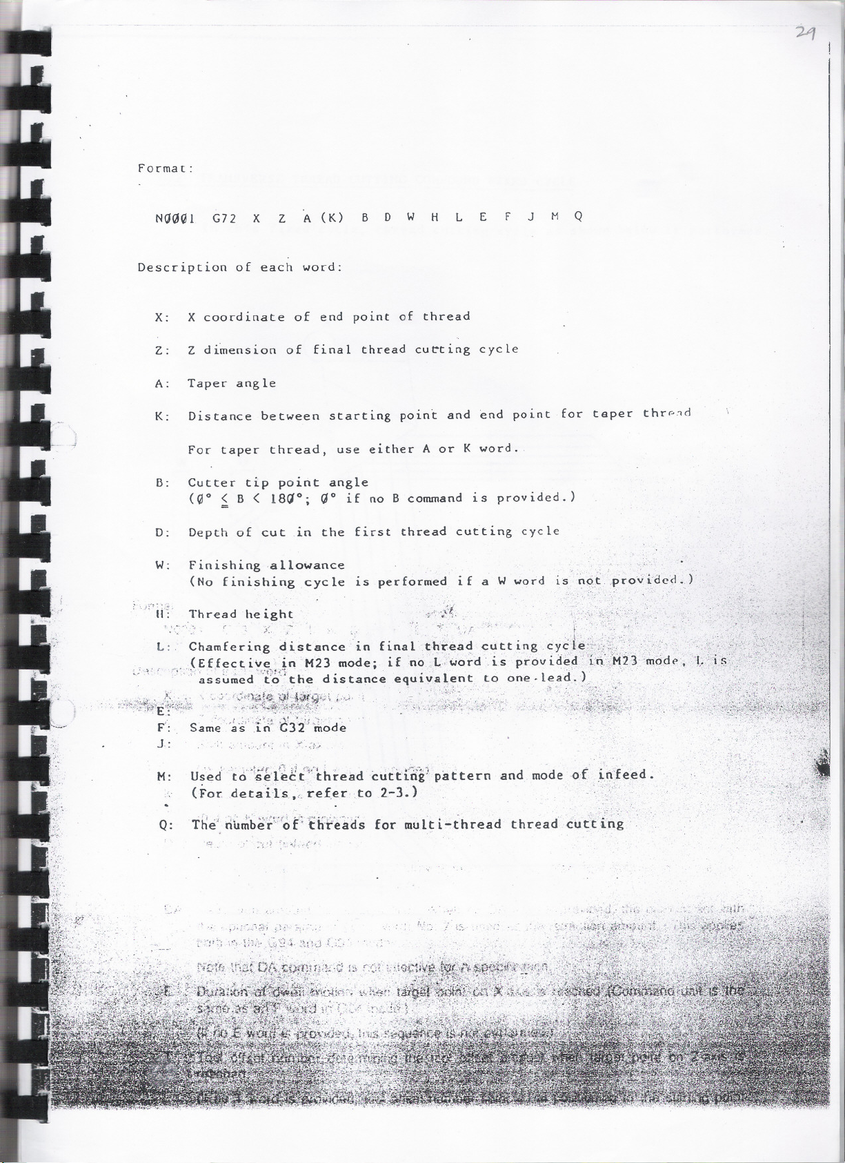
Format:
Na(.J(.Jl G72 X Z A (K) B D W H L E F J M Q
Description of each word:
X:
X coordinate of end point of thread
Z:
Z dimension of final thread cu~ting cycle
A:
Taper angle
K:
Distance between starting point and end point for teper thrp~d
For taper thread, use either A or K word.
B:
Cutter tip point angle
(Go ~ B < 18ao; ao if no B command is provided.)
D:
Depth of cut in the first thread cutting cycle
w.
Finishing allowance
(No finishing cycle is performed if a W word
. .
1S nQt .pro" idecl.)
" 'Ir~
. ,', _.,J~ff~<;tiy,~_..Jn
~.~ , . ., ., '4 '1" . I'.. . - .
Thread height
,:'.~ , Y. .,- . ": ',r. ." . f. ".'
L:. Chamfering distance in final.threaci cutting cyCle::;:.;::;;L.'.
M23 mode; if no L.,word.ispiovid~d Iq:\:)123'm(jM,
.. assumed to the dlstance equlval.~nt to one.l~ad.
. ~ .~
F':
J.:
M:
Used' 'to":S'~'l~E{'(thread cud:i'rif pattern and mode of itffe~d.
,,"~.
(For:deta'ils .(,re.(er .to 2-3.)
T~e; ri1i~beF:'of th:t'e~(fs for mult i-thread thread cutting
Q:
.~.". ~. :
~ "
." ..;';."'
..

-- -- -
----.-
..
..
G72
~
t' I
I
I
TRANSVERSE THREAD CUTTING COMPOUND FIXED CYCLE
In this fixed cycle, thread cutting cycle as shown below is performed.
A
(2-
w
H
Starting
point of-
thread cutting
,.........
..
I
I
II
"
'-'" I.~I ,.,p.., ~
.
w:.. ~'4~.' ..,
...
-~.. ~....-. '1' 7'... ~
.. "
.' c::.:,". ,.
.
. '
---1:
-- -~-- .
X
I
--~---:.-~.,
' ... ~...""-:,.:Y
L
: ~ ..'
l
Z ; i-:---
.
-,. :
.,.
.:.:-

Longitudinal Grooving Fixed Cycle (G1'3)}
In G73 mode. grooving cycle as shown below ISpetbmed.
'rrnrrnrrnrn'
'r////",,////, ~
T when poS.tlOn"'!jIO _<'<JJ".n"".JL~..
the coordinate 01 End pO.nl
largel point is made 0
I"", /' /'/' ',~ ~
I
z _. .-.
_ iJJ
l-C)
x
- .-.----.
Format:
NOOOt
"'f:_~l.::i:; :..
G 73 X Z
K 0 L F E l' OA
OescriptRfOJOf~ach word:'
x ).,><. coordinate of target point
_j".s";ffpti(.R~::J: 0<1::;; Wi). Ii. .
.~4~' ;"6 :~OQrcfinate.0; target
. """-;&}!'~
~-~..~,..,..n.'" ."'
"
. ,."' ~'''''~, .irt..\R \. ,tarU~ '. "'1
I .~ :~:.Shift ainotint~in' X-axis.' irec'tion
.. : 2. (;'Qr;.~.rc')~r: : '; .J! i'.,:f.':.!.t"!.~r;:.f
(in,diameter; 0 if nol word is provided)
~. J~l'~J' ~;'''''\;1' ." ~ ",", ~. .~.'t'g'rl"f(" .
K :::~PJf~~.ci9.~r:tt' .in~4:~~i~. ~rrn~tig~
, ~. - .", : .,.,. .
_ ~ ~(O.Jif,,'1q,KY!'0rcfis:Pf~Y!P~<;f). ,
t.
:i''''~'
. oint
''~
.
!
'H''''-C'
.
. :~
o . :'O~plt{6ft:ut(infeed.~iWc5\1ht)
L"l: ~TbtaHnft;edJamouht"ioiliiooi withdrawal motion (in diameter; tool sequence is not per-
.forfO~d when L worp is)not .specified.)
.
"
.,.
. (,~.
.- .~
~ . ".
..~,
OA: R'etradion amount
oia" 'is"specified. When no OA word is provided. the amou[Jt set with
;,the :9PtioQal.para,!T\ete~ (1Q.~g.word) No.7 is used .asJhe. retra~tipni~u:noW}i.~..~i-'tbJ~",~ppli~~.~t
bo.\t! i.qJh~, G~4. ~rJcf~~5~rn9jes. '. i;';<"'~,:$ .~,,' '::'.f,o.c:;'~'>:),~rJi},!;;;~',';;~~!;'~f~*'2'.;,.,
.tl8t~'tf1Mtb.tfd{mm5n~~S\not1!ifective forA speahciiiidf!.' ":;..::r~;',:£r.9~'
'. . .::E~ :i~~iridn;Pt'd~eltlb~lt8Ri:l*an~\';rg'et:p6Int:".b6!:~~~~~~~~~~#*i
~. . "
. "",.f!!:£.'T!P_'-:Jo5:;~"', ''''''.5~ !n-t"
"; -'.«; <sa'!le,'<!S on rc'worU'1n:~ :moue: (:-" . .", :: '~;~lJ't;.:;:::;',.,',""V';
.,.,..1"""~~t.-.
~
. !. ".-.,i;~;~...'\~"'~JV:1:~Xf-t.:H: ':. ,. '.. . .- ~M~,"'~~~Jf:!~f;.G('1 .j.:;..-€ :!t~'M1;di.1u J...,~~..;:.i:::
'...,.
.
. :no~E: \Yo'rd'!S~.provid.e~a;.Jbis$e.quence isnoi".c:~'~ ;:,~"-'-,'..I.,,'\r~',,..'
.~1~ki.~.(J:( di'ti'(D~f~1 .i!~~~,.i.if-~j
...:na...., :.o.I"
.
'
~
.
~
fs'e(:numDeh:ij~mihi~cJ'~:ihe,toolJ
. ",-, ...
'
~"~"'f' . ".' .";, ,?"""'"",;;:".,.,!\,.~ :."'-
O
~
"r..: )" "
.
.. \ij,t~
. ,. -i~""¥""
~
.
.
.""'\;>'1,';

Transverse Grooving Fixed Cycle (G74)
'In G74 mode. grooving cycle as shown below is performed,
T when posilionlng 10
lhe coordinale 01
largel poinl is made
z
r - - - - - - - - - - - -- - -- - - - - - - - - -- - - - - ~ - - - - - - - - - - - - --0~~ ,.,.-
C
I
J End pouIl I.: ~~
r
. L.:~':-.J
X
-....---.
Format: ' ,.,_ '.
'.~:. ,"
.~,..
NOOq1..~G!4 X Z I K 0 l F E T DA
. ~~~~~
.'
-." _/
, ,
...~~~"
r::: "C
t~~~~
t:,-,-~L_
Description of each word:. .'
X '~:9<~C9brdi!,ale'Of1~:r9~1~~itn~},~~~!'Jri,~.:
~l':_~cka~(7. ,:! ~;~:~.;;.».::'(:~~'?t,.r.\1.-~(ryc:t,,~.n
Z : ~~,;e8s?(d.j~.a,te.pf,.~<:trg~~ e?~t~~j(!i~' W .'
. '. -.' "'. ~ ','"
..t':.i. ~~~~~1~"J~YC'~
. .:'0,
,,-...-.
:"Shift~mountin X'axis'dii~cti(jn ~..'\" .
.. :(i.n~~.i~m~teG:.~.:if}1~:L~p!.~~~,pr.,?vid.~9)
K ::'Shiit;amount in Z-axi$:d!iectiorf~;" .
(O,jf!l9,.l~)'~9~e~,prj>,!~?~)~,\_.;;;". ..'
- ;::'
,~r
-
o :. Dep'th1ofeut (infeed' amoui1t)" !'.';'.''.
L
Totalinfeed amount fo(tOoI'withdrawalmotion
(The sequence is notperfo.rmed when l wordis not spec:;ified.)
:-:_ . ,J' .,,-".-.. . . ..,;."' ~ _ -~".. '.
DA: Retraction amount "a" is specified. When no DAword is provided. the am()ilot~et with
.t~e,>!?pti()nal~pa,ra~et!3r JI9.,n9.,Y"0r~), No.. 7 is P~~.rP.~€!~;;:fl:~,~~S~i~W.~~~~~\.:1~tt!!§.it)P.(ies/ -..'
~._i.;~9%1?!.~~.~~~ and G.95~~~.S.. -,,'. . .'
E :. Duration. of .dwell. molion.iwhen..laroet oolnt.. on i.z~;.ireache:d';(C9m'
'~~&~~~~1li~Ti;;.~\f;~:j:,~.:,j.~~r
.~-~~~.~"."31~.:~~
..J ." .."~
--.~ ,,~. I:.
"'/:J>"..-;".
_. ..
--.--
-- -- ---
----
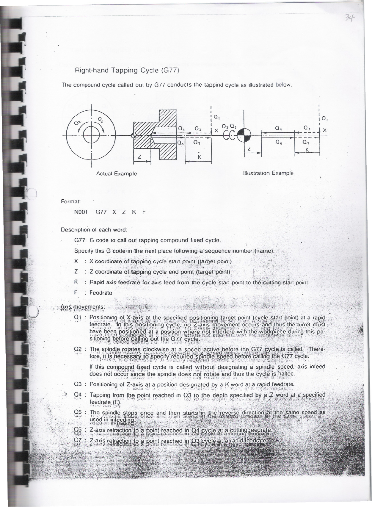
Right-hand Tapping Cycle (G77)
The compound cycle called out by G77 conducts the tapplnd cycle as illustrated below.
I
I
I
la,
o~.
.
z
K
Actual Example
Illustration Example
Format:
N001 G77 X Z K F
Description 0.1each word:
G:17: G code to call out tapping compound lixed cycle.
Speedy this G code;in;lh~ next plaee following:a'.sequenee number:.(na"-Je).",,;, :
X X coordin~lte:o(~pping cyelestart PO!g!'Jlafg~t PC?,nt>, .;, }
~_ '" t '.. '.. . .. ,;-;,; '..', ,.~. .. . .;. . "
Z Z coordinate offapPlngcy~le cnd pointJtar.gefpoint) '. ~" .".'.,: " ..i-. '.
K : Rapid axis feedra(~' 'or aXIsfeed 'rom the Cycl~ 'starq>Olnt to the~tting'5t.~rt .point
. _ ~' '~:.~.."~;.'::-: / h '". :-:';:,~"t.;: (~' ' .'~ ". " ..~.;-:.:~j":~i#:.,'~,:;-: -; _';~- '. .'
. -
- .. .
r : Feedrate . . .
."

--- --- ---
G75 AUTOMATIC CHAMFERING
When cutting a workpiece, it is often necessary to chamfer the sharp edge
(either 45 deg. chamfering or rounding). Such chamfering can be
accomplished using conventional taper and circular interpolation G codes
such as GQ1, GQ2 and GU3. However, this Automatic Chamfering Function per-
mits chamfering t6 be done in a simple programming.
Commands used in this feature are:
G75:
G76:
L
Chamfering at 45 deg.
Rounding
Size of chamfering
4S DEG. CHAMFERING (G75)
+X
(Xl20.00 250.(,10)
E
-;
(Xl20.00 2115.00)
D
,C(X120. 00 Z120. 00)
I
I
B(X110.00 Z120.00)
A(X50.00 Z120JQ(,1)
,
+z
.-
. ,
Wit-h the,c~ands above., the .cutting tool moves Jrom:Point A to~~~~4'.'.then ,'"
"."<0'D "thus au tomatica lly ,chamferioO' th,,'curn'r."tE~ 5.de.. w.i.H'1>!I~iJ"" f."
5 ;!~~~~i1,.,
'.Sp~cifies chamferi.ng at 45deg.
. ;:~.-i S~5. fr~c~~' ~ -. '. '.:_I: ~,":::":'
X12~: X.~Q~rdiQate of Point C
" _.t_..,.., J .. .
L-:5 :
S.~,;_e"oJ, chamfered face
'...
-;.,i
:~.

G76 ROUNDING
( XI ZII.P8 B II.P8 ,
E
(XIZc1.pll lll~~gl
o -'~CCX I Z,.P8 EI ZU')
BCXII'.~~ lIZ,.'"
ACX511.U l IU." I
+l
To cut the above shown contour along the Points A, B, D and E, program as:
G76 G~l X12Q
L-S Faa CR
after positioning the cutting tool to Point A.
With the commands above, the cutting to~i moves from Point A to B and then
to D, thus automatically rounding the corner .at 5 mm radius.
G76: Specifies rounding of corner
X12Q: X coordinate of Point C
L-5 :
Radius of r~o'~d'i~g:-~'ircle
Its sign is 'd~~~f~i~ed by
"+" ... ..when i-axis (X-axis) moves in
( ; ..
./~ '\'" f~""'- ~ "..
. J'::t_.:.c..::._~... '.. .': ."'
the direction of a)cismovement;'
,<",
. . . ~')
,~.~fter ~:X~axis'{ Z-axi s ) moved.
"_" ;;?-f~i~~e~~(i~i~f~::~"(~~~xis );aioves .in
. . after X-axis (Z-axis) moved.
By. c~mma~4h~g .the coordinates of Point E. .,thedcutting tool moves from:Point
o .to<PoiWt:':~E.~~'~: -' v . . . -..'> -'....
'--::0,-:(;0..
"'NOTES'
/. i :~~
Z ~~t~~~.. ,. .
.t-,'~
. .
.':...;
,..,."
1. (;75/G76 is effectiveonly in GOI mode. If it is speCified in otheithan GOI
.mode, it causes an alarm. . -.
"~
.....

-- - -~-
G90/G91 INGREHENTAL PROGRAMKING
---~. - -
With OSP S020L/OSP SOOL-G, programming is usually prepared in absolute
dimensioning system; however, it can accept the commands expressed in
incremental dimensioning system. Combined use of absolute and incremental
dimension words .i~ also acceptable.
G codes" used to select dimensioning system
.G90 Absolute programming
(cancel of incremental programming)
when the control is reset, it is in the G90 mode.
G91
.............
Incremental prog/"amming
Example(positioning from point (1) to point (2»:
~;.
" (2)Xl00 ZS0
,"(J, "'". ";.~~ it'.." l"~.~
;..
X
Incremental
.~>&~~~~ .
* Des ignate ciimens ional d i ffere''nc~s be-
tween points (2) and (1).
. . . . ., ~,:...,.,.i.;:':::*~f~~~ff~t,i,.:_:.:.
N.ote:
;
_Absolute
In 1ncremental programm1.ng. X word shoul~ be express~d ."l.,n""d " """
-
::::,,;
))
'
"\i~'
I
~l~;~~:.
,,:.'~-',,,

,.
--- --
LAP
LATHE AU'1'O-PII.OG8AI FUNCTION
GENERAL DESCRIPTION
LAP (Lathe Auto-Programming) is the function to make use of high speed
processing capability which characterizes the OSP500L-G/OSP5000L-G series.
With this function, the control automatically generates tool path to
produce the requ~red part contour.
In this function. the program comprising, dimension data of the final
contour to be finished including rough cut conditions is prepared as the
Contour Definition Program; when it is called out with the cutting
conditions specified, the:control automatically generates tool- path for
respective rough cut. cycles, and then finish the workpiece to the
programmed dimensions.
... '1,.';0.".':
,...".' :.'" :
This feature permits the programmer to complete the part program simply
picking up the dimensions specified in an engineering drawing and, there-
fore, it simplifies programming JS well as it reduces programming time; .
this furthermore facilitates tape check procedure and also tape punch\
procedure.
Various cutting modes available with the LAP can cope with any type of
cutting intended.
Features of LAP are:
1) No
2) 'Tape'p're'~:ar~t~on time. can be,. gr~atly reduced. .'.: ..'
:;j) '.prog'~a~F~~::;rf~1t~U'gh'
. manua~ calCjl.ation~hUeprogramming.' . . ,. ,', . : :./: ."
:.n:.'~ ,".' u. ~3S:"7'.:T;,~:<:".t1~~~., ;.:~:~H~'11.:~,~:'~tl{':',:.)''''<::~ ",,;."~.;~;::t'~.;~:L:=,:'~:~;':;'~',';:':/;,:'~~~::'"'
4)
' ange .:0 ifU'ttY'g-'conu ons!;uCn' as ep~n 0 . cu,an .' e,e ra e': 5:;">/:"1""
sp~c.i>a( p.r;ogramming languag~ is neede4.. The. :same":;progr.a~i'.1g .iIi~riner
as
ili" 'c'onven.t'16na f' p'rograninilai~Cteduiiqu4!:":can 'ha-ridle':'the t..(p fulic hon.
- " ~ '-:;.1 t ~ .;..1'. =: I .f" . ' f'j ._=.!.,",q -:..- ;.,f.'.. ~ ,~,,!-~,:,,!:.':~t:;:.~,' ..:. ." ~., : .c : J.§ ~,
~ r ." ~ ~ . .
hit" 'ti~~:~#~a-:rt'fb~>ifiirtlii~ t~ti';~':f~ri<f\~this 5ini~~j1fi e s
'
.i
' "
t
1
'.:1.,.", "'
...Ht.:~ ". ""'
.
ij
J~~;, '"'
':: 't
f
,t
d olt
t
d
.
'
...'
'
.,r
d
f..
t
.
.
Ch
.' . - . . , '. . '.
i.:1:t~
"p'Gm::na.n~".,., <~
f
M
.'b
.
..,:
..1:J,;.:t;
i
.
.
.
.
POSS~_~:;~~Y~~~i!,~:"'~E:~;~~~~~'. .~~~~Jil;~.
FORMAT (Ct}tOpE~,:,~Q'" . ( ".!,J':,-: <..",: , ~,<-'", ,"~. -:~-\ ~ '. .. .,. '
.,.g,8~
,... -,
C81
G82
G85
\or~>\"'t... - t ~ 't'~~p'f. f~~...: ~." ./". i.~r 1.,;': ~ C.!~) ;>-:> i" ~-i: '1t--
E~,dJW~!r~~~~~.~l(:-~e,~i~~!:~lc~~i! :t!~':".~<'""'ie.!;>
.";.. -:.' ..;' ~..:.Oc t:.. .;'::;,. _ :) ~,.. t'., -J)" - ~ .-t.. -..,:.-". .
St'ait :ot"f"'c'tiiltoiii' definitioh~,"~lon'--:ltu(U:na'f
~,il':..,;~,1i{U;~;~,.,t,..,.(';.. (;,. ;.- .'~'.''.i,'f~'t;.~, ~r'~],:,.*~~.. ':
Starf'of. 'C'ont9ur defini tipn,T.ransverse
~i no .;.".~.t:'I.t:..- :-. ~.'.''!l .:'P{; '~'n ~u -~..
'. ,~r~''''.{~';''(i~l''' ,-
Bar .t'\£rniri'~f rough cut cycle
~'i;"{ ~i~.;;~\'
~'" >.
by
.
'
.,,4i
-"'~~
G87 Finish cJi 'cycle
"
'..
. .
,

~
-.
180
TOOL NO,
35
TOI T03
T05
(17
V"I
V"I
Q.
-----
11"I
..:1
Q.
\
.'
,;.
11"I
oj
Q
.',
'-
N
-
\..
LR 60
ClJIT1~ SPEED
SELECTION
-
....
T:HJi. BIT
CUTTI NG
&J &J W
150 H/MlN
00 ROUGH
120 M/MlN200 M/MlN

__~ ~____ _ _ _ __ _ 4_____ _ _ _ ____+
------------------------------------------------------------------------------
'N G
-----------------------------------------------------------------------------
: GOO
: G50
NLAP1: G8t
GOO G42 : X25
G01
x
: X5.00
I
I
: X30
Z
,
Z250
I
, I
I
I I I I
: Z201
,
Z198.5
,
L F
I I I
I I I
I I
I
.
I I
.- -.-
FO.15I
S T M
S3500
I
Z175
X33.38
G03
G01
G02
GOt
: X35.337 : Z174.208: l1
: X45
: X53
: X55
I
,
Z151.477,
Z144
.
Z140
.
: Z139
L4
,
I
\.
Z110.979
I G02
: G01
I
I
,
I
.,
"
: X55 : Z63.021
,
,
,
.
Z35
: X62
,
.I
X62
.
,
.
L60
. ""-., "_.0 >...
41
I
I
.
I
I

"" .-
G87 FINISH CUT CYCLE
Format
NQ203 G87 NLAPI
L--J L-..J ' J ~
NQ2~3: Sequenc~ number
G87 : G code calling out finish cut cycle
To be provided right after sequence number (name)
NLAPl: Sequence name in the first block of contour defining bl0.cKs
Blank: Enter either tab or space code
u
w
Stock removal in finish cut cycle, X component
Stock removal in finish cut cycle, Z component
u W
l..J l..J
.,..:,..

--~--- --"-- - -- -- ~--- ---" -- --
EXPLANATION OF LAP FUNCTIONS AND PROGRAM
Tool Path and Program
Contour Definitiun
- Longitudinal Turning
Tool chance po.! t tC)1\
(ZLXtl X
Ct.rtOtnc pOCI t Ion
I' I
..-
1&11,11 'r.
,XA Z
4' II:' - u;
,
1/
"
'(12..'0'.)
%
.-
IM/Z
i ,;; '.~~ f~ ~:, ~.~ _.. ,.. . ~ . .. f'
,:~LAP ICSI -- ~ "'---- ~-- ---:'
:~<J(Jal ;CI1(J';"X.:'~:Za"'" .
:tI<J(J(J2, Cl1l Xb Zb
:~(J(J(J3 Xc Zc
!N(J(J(J4CI13 Xci' Zel 1a l<d Fd" sa
: ',:t.[M<JQS. Cl1l . Xe . Ze Fe;';'.$~
,':,~st~iiOO,;::::~o~s'~5~h.~:; Fii:1o
,::;,NO(JI1S '.:.'~S<J'>"E';:;-.~..;. - ..;.- - - - .,.,:::':"
,.
..
" .
NI1HH CQ(J
NI1102
'NOlG3
{$ ~"";,
$
. ". Rough Cut Cycle
.~ l.f? ,~-..;:: :'":
Xc Zt
Xs' Zs
spind Ie speed for tIn Ish
. " .'
Feedrate (or ~ough 'cut cycle. fough
/.:cu ~.',,.~l~~g£~~'~v~t ':,
.~~~~:J~t:.f~!.'c~~i?~l~:~~:?i.l\i t ion
" '"" . . "
.'
- '. ." " "
. .:.~"-'7'~}':~X: :~'-'-ft,_;/<,"
" ," ;<,,#~~j~i.\X~~,~~~fi,7'"
.~
''"'End.of contourde~~nition
anclfeeclrate up to
sco~kreDOv~l ~unt in finish cut
cyc Ie' .

___"_._, -__ _u.._
..---- - _. <-
Bar turning cycIe(G85)
GOO X800 Z800
G50 S3500
NAPI G82
GOO G4l X82 242
Gal Z45 Al35 FO.l8
X60
Z50 Al20
Longitudinal/ID(G81~ and End face(G82)
45
X37
Z52
G40
G80
NAP2 G8l
GOO G4l X43.5 Z5l
GOI X38~5 A45 FO.15
Z33
G03 X32.5 Z30 L3
Gal X30
Z25
X25 Z20
X18
G40
G80
GOO X800 Z800 M41 M03 S600 M63
NTAI X9~ Z51 TOI0101 M08
'
G96 S150.. '. ,',t:. .'_"
G85
N
_
_
_
API '02' iiri. 4 wo.~i f,O. 3
..,'" .
,
~
- "30
~
"'- :
I Q '&
--~
_. .
~
o
D
SO I
---"
',;.'
.:~Dj;tJ<90'2:51' .. .
.~,g9'7":-X800. Z800 $600 M05.,M63..
. :~NTA2 X90 Z52 S800 M42 M03 T020202 MG3
);:/;:9~6' S200 '. . .
, 'o:;'G.'87,:: NAP 1
'-:.:.' " '.0 '0
!CO~G97X800cZ800 S800 M63
~..~ ,
NTA3 X18 Z55 T030303 S2300 M63
,G.9 6:.$ 15 0
'G85 NAP204 UO.3 WO.l FO.25
GOO:':.G97:Xl~ :;.Z'S5 52300 M63..:':"
X800 Z800.' "', :-,'., .,'
NTA4 ..xIs' Z55 '1'040404 S2800'M63
G9G S180"
G87 NAP2,
GOO G97 X18 Z55S2800 M63
X800 2800 S1500 M63
~TA5 X34 Z56~T0505
G71X40 Z40 B60 00.4 VO.05 Hl.5 Fl.S.Ll M33 M7j~M23
X800 2800 MOS M22 M63
M02 .
~ .--- ___Ujj
'
60
,· /
-,.. -~ . . Ira...;,
1
;
/ "()
1
.:'J;,s
~
I
-'::'-
"~ t ~
1
~
I
~~i
,

JIll
"--"--'
(G96/G97) PROGRAMMING CONSTANT SPEED CUTTING OPERATION
--
When the constant speed cutting function is selected, cutting at
cutting speed can be performed. This feature can reduce cutting
also assure stable'finish in end face cutting operation.
Format:
G96 50000
G96 Entry of constant cutting speed mode
50000 Numerical value in the'5 word-expresses the desired".
cut~ing speed.
SIGG means IQG m/min.
G97
50000
G97 Cancel of G96
'J
j Soooo
" ,1
,:i~,~~~..; ,-,,'.
',' " When
.........
the control
Numerica
spindie"speed~' ,~: ';Jf"':"!'," i" ' .
I value:,'of;:'the Sword e'icpres5'es the ,'desi'ree,\
is reset, it is in the'G97 mode~
-:' ,.:.
a constant
time and
;,.~j&xamp 1 c
,t
,~,,~, __
"
.t ,. .
,i . , ~':~','
,
,
,
I Noaa G96 SlQG
.:
Nooo G97 SSGG
.,
G96 calls for 'c'onst~mt speed "cOtt iog modeand:":the
commands following this block are ;;!I exec\lt,ed in
this mode.
..:;........
SlQG lUG m/min.
G97 cancels G96 mode, and' cutt ing after this block
is carried out at ,8 spindle speed of SGG rpin.'
..
"

r
- - - -.---
5. H CODES
Code
MOO
MOO
MOl
Associated Information and function
M Code
Up to three numeric characters following address
character M are used for specifying various miscellan
eous machine functions such as spindle CW/CCW,
collant ON/OFF, etc.
~rogram Stop
When MOO is executed, machine operation goe~ into cycle stop
state; spindle rotation and collant supply are also brought
to a stop.
To continue ex~c~ii~~ ot-the part program, press the
START button.
This program stop function is effectively used for measuring
finished dimensions and also for removing chips during cycle.
Optional Stop
CYC~E
':-"M02
"','
',' "'-4 . .", ",.-. ' "
M03
MOl performs the same function a.s MOO Program
that the control ignores progra~ed MOl codes
OPTIONAL STOP 'switch is ,turned""qN.
,':'t . . . .: :.-;..:
. ~. ,'c .;. 'f
End o';i.,P,rogram-
M02 provided. at the end of a p.it..,t,:"pr~gram ".r.esets ti1e
"
~,~"=-",,,,,__'''''.~M_''''''_-'''''''_'''''' ,.,... ___" ., ~ ~...~.",:",~~~ , .- ~ ~"_'''.''''~''''''''
. -'i:
. .~: '.f~~:;~~~-'.', -~.- .
StoPi.except
unless the
CW Rotation'
"
~M03~s~arts.the:~pindle ~otation,'to advanc~ a right handed
screw into the workpiece. ,-
..,.~_....
... ..:.
MG3 rotation /"
.(3---~
Viewing spindle
c:;ootro 1.
l: ,... _
'-' ;>:~
"

Code
Associated Information and function
M04 CCW Rotation
M04 starts spindle rotation to.retract a right-handed screw
from the workpiece.
rotation
M05
M08
Spindle Stop
MOS stops spindle rotation
Coolant ON
Coolant OFF
Cancel of M23
J~~ ~- J ;' .
.Chamfering ON
.' "..." j ~
';;;H1j4~~ectjtes chamfering 1u's'fng
G33.thread cutting cycle.]
..~ 0"
.';f.at.tern of thread cutt4;?g
Patt~rn of threadcutting
,-". ~ :.
'\. :... '.
.'
..
Pattern of thread cutting
..
"..:
..

.-- ---- - - - --- - -- - -
I'ROGRI\HHINGEXAMPLE
-
~..
~'-
L
>
.., \.,
...,.-
~~ t~
X'~.;,
: - 'I
.'
NO
< 3
.- 6
.; : r
1
2
4
5
"
0.0. ROUGH CUT
0.0. FINIBH CUT
CENTRING (CENTRE DRILL)
-GROOVING:
DRILLING (UIA. 6.8)
('Wl DTII 3Jj\m).._
..
..-.~
THREADING (M30xl.5P)
7
TAPPING (M8xl.25P)

I
I
I
I
I
I
I
t1
"
- .
-"
~
;"..
~.
~XAMPLE :
~OO X800 2800 , TURRET RETURN Tv ~iMiT
G50 53500 ( MAXIMUM SPINDLE SPEED CONTROL
GOO X800 2800 M42 M03 51000
NLAPl G8l ( Start of contour defInitIon
GOO G42 X24 Zl01.
GOl X30 A135 FO.15
260
X40
X50 AlSO
Z40
G02
Gal
X82
G40
G80 ( End of contour -defIn!t.ion
NT1 GOO X82 Z105 TOI0101 M08
G.9 6- S 22 a
G85 NLAPl D6 UO.4 WO.1 FO.30 (-- Call for rough cuttIng cycle
.
$G84 XA=50 DA=8 FA=0.35 <~ Change cuutinq condition
GOO X82 Z105
G97 X800 Z800. S1200
NT2 X82 Z105 T020202
. ..G~6,~S25
, ~'.'.
'''
' .
.: ):G~?;L~~Ap,J"f.S~ ~_:-_;__:--- Call for fini5hcutt!nq cyclei"">
":!-,'". .f!":_ " ,._ ;-;<;~'~"" ",._,;.:..>~. .
'-':"J .,',",-..'d-.,''';-:. "'~'-:',:."'""h ~":O:f~;'"__'~..
",
O
0
G
. ?"'~.]::~:~~~H) O.}j,~'8. QO S 1 0 0 0 " ... ..' ,;.
..,,,.-(-_-,,.4f~~..,,;,;.. ~t,~~:f,~~<~.~fEij.::f":. ,'.". .:. #.' ~"- .' .' _;.ri..":,,;.,.~,, ".:\.';.,;..;"t.,
~:N.~)~Jt'j,;z.1:~n.~,ro) 03 (":.-- -,- - - - ...- :-.- Ce n t red rIll.;.
'~'~~~"_~;~~~~~~;.:.t'.~:.~ ,~~,~.~,.:" ,.~: ~! . ,- ;'..,.,;.!"",' ',,;'; t'- ~
X70 Z)O
X78
A135
0 .
.
""':
'.'~:
..Y' 6."'
X
2
Z
l10 KO
~ "
' ~'
' '. '. .
l
O
5
".~;, '-.. ; '~':"'_' -. :1;. ,-__~"~_ .~~','
.....
,
,.
~. -.
03 ~'L6El
-. ~.
,
EO.S T14 ( Grooving ~ycle
. __ n _ _ __
- - ---,---.-.
< :.: :-- Dr i 11i09 cycle.

TOOL NOSE RADIUS COMPENSATION
FUNCTION (Standard
The data processingperformance of the OSPS020UOSP500L-G series is all the more enhanced by
diSllnctive feature: The Tool Radius Compensatiol) Function.
one
The tool tip point radius of most cutting tools used in turning operation is the cause of inconsisten-
cies between the designated tool paths and the actually finished workpiece contour. With the tool
radius
gramming. .'
In die Sinking or milling operation. cutting is performed by a large diameter milling cutter. There,
control systems are equipped with the Cutter Offset function where the actual tool path generated is
ollset from the designated path by the amount equivalent to the radius of the cutter used. This is a
stan(r.~t(1function with OSPSOOOseries controllers: However. in comparison with the cutter offsel
funcllon. the tool nose
compensation function. such geometiic error is automatically compensated by simple. pro-
compensation function offers specialle~tures that are requIsites for lathes. \
for OSP5020L only)
.~.~......
.. ~.
ii~.
k. .
~1i.
Tool Offset and Nose Radius Compen$ation .
. : I~'.~ttmllng operation. va~ious tYP.es and d"fere!:'t.s~apes 01 tools are us~..to' hni,$f:\:og~:worki>:;E!.cet.:",",i.l>
':.~")£t;~~,~.t};n~ tools. 00 c~ibng'toP~S. rough cut to,o.'S. (~~!$tI.;C~tt90ls. driU";~~f;,{1~~()~q!ngIY;.:~h,~':}~~t1.~:~tit:~~~..";,,
:);.~.~.~~~::r~dlus compensation function has to be actlVated.slmultaneously Yf~t~,.;.tlj7Jqo~;~f{~e~~YPS!}g3;:.;:{;:{~i~~;riit'
.. ~'::::;;'~~~:~r\: . ..' '. ~.;:.'~"~.,..": '.
..,."",:ii ":; <., -t. .., II. ~,..,.. .. " " ...,,~...'-- -. H . -.' ."..'\."" o. ."" ,.,, ...~.~~.~.~:;.A..~:~;;. ~ - . ...: - '. - ~- r;.,".~~~~<~. .~_--~..~,..~:-~f~:T\..>;_"
Nose radius "
'compensation I
Position offset ~
..
'.
.<. . ..u~:',~. .,:- '" .~:.,...~<,.~;~~~.:~~'::.".~v'r;G~.: '!l~'.t3f:~:!"'::P
+
" .' '. '.. ',.' .:. ,...
1he t~~I'noseradiLJs,f~p~tionis~ctlvatedby a ~ix~(;'igiY'''Tcommand:
. T 00 00 00
(01 to 32)
-II Tooloffsel numb..
Tool number
(01 to 12)

Geometrical Cutting Error Due to Too Nose Radius
If culling along paths A-B-C-D-E in Fig. 16-3 is intended without activating the tool nose radius
compensation function, the portions indicated by hatching lines will remain uncut and cause a
geometrical errors. This is because the 1001setting is made to locale the imaginary cutting
point P in Fig. 16-2 al Ihe datum poinl and Irace programmed path as controlled by NC
commands. However, the actual cutting tip point is not precisely located on that datum point
because of the tool nos~ radius and this produces geometrical errors.
POlnlP
F,g, 16.2 Tool SellIng POliti
FIg. 16.3 1001 Palh and ResultIng Erf:Ur
. WithoUt 1001 Nosa RadIus CompensatiOr1
.- !
The tool nose radius compensation function automatically'c9mpensates the inconsislen~y
between the designated and actual tool paths caused by the too' nose radius. .
..., . ."
. :~~~~ ': -,','
Comp~n~ation Movement
With ,th~0''90' ,nose radius compensation function activate'!, o.!I}E3,.Jool.path is compensated. as
iIIustiafecnn ,~ig~'16-4 to eliminate )he portions left uncut; sHown in Fig. 16-2. This assur'es
accucate'finish as programmed: I. ,.d - . .', '.' .' ,
. .~ ~ ,; .~. ;~'~~.-.~":'~) . - .
..

Programming
Programming commands, G. M and T codes. used to activate the tool nose radius compensation
function, are detailed in this section.
G Codes
G40: Used to cancel the tool nose radius compensation mode.
G41: Tool nose radius compensation
-Left
Used when the tool moves on the left side of the workpiece.
G42: Tool nose radius compensation -Right
Used when the tool moves on the right side of the workpiece.
Note 1: The term indicatingthe side of the workpiece, rightor left, is determmed accordmg to
the direction in which the tool is advancing.
)<. .
A lurrcl
- lwo,saddic
st)uc,hCillonn
ZB-
x.
G42' Righi 10
j
./
workplcce
lell It) _
workJlI(,ct!
. ,
f.g. 16.5
"
I .~
".
, J.". ;..~
T Codes
"
Six numerical, characters 101l0Wll1gaddress character -r specifies the nose radius compensation
number~ tool number, and tool offset number.", ...'<,'
To sef 011set data through the keyboard, 3'2 pairs 01 compensation data for the tool nose radius' and
tool offset function can be entered (01 through 32). For the tool number, 01 through 12 are
available.
T 00 00 00
-II Tool ollsel numbe'
Tool number

Tool Nose Radius Compensation Data
As seen. in the previous section, programming procedure to activate the tool nose radius
compensation function has been simplified. However, to finish workpieces accurately using this
function,the toolnose radius of the tool to be used must be measured precisely and the measured
value entered correctlyinthe NC memory.
Measuring .Nose Radius
Measure the center of the tool nose circle with respect to the tool tip reference point which is taken
as the imaginary tool tip point for tool.presetting. See Fig. 16-6..below.
The imaginary tool tip point indicates the ideal tool tip point which can be expressed only by the tool
ollset amounts withouttoolnose R. Ac!iJally,such tools are not present. \
When the control has no tool nose radius compensation function, it controls the coordinated <j:(,!S
mohon so that the tool tip reference pOintfollows the programmed path.
Ideal 1001Wlthoul nose R
(hatching lines area)
-,;-
~-.
i '
Imaginary toolb~
".- . ... . . '.';" ~
.r .-~'.' ';";~".'~" .:'" .'_ ',' ':;"',-';'" <, ...-
'.f~'~"~''':>'::.
.~~
.~.
.;: :{~~'~;ik;:>~:!- .-::.
-.f~:.lnt~e_.medsurement of nose R compensation data, b~itiiti:~:i,oseR compensa~i~h'1irnouniand the
:>.d.l.rectlonof nose R center inreference to the imaginarytQQftip.
. " . : .
~;j;{pir~~tionof nose R center in reference to the imagi~&~t~OI'~t~P isexpres~~ in the.'.fOIiOWingtwo
~¥i~~,s':..:. " . . '.;'~f~: i.' . . '
!:~a.Lt~ypos.itive a('!dneg~tive signs of X, Z compensation a.mounts
.-.":" 'Y . . . .
~~~;t~) '. .~By a P number ,.
< ;.t.:~ -". - ::." .
~~:h";Umethod' a) is used, positive and negative signs are determined from the position of the nose R
" ) center in reference to the originas in Fig. 16-7.

x+
x~
Cenler of nose R
z-
z+
. .
O
rlgln (Imaginary too lip) /
I
.. /
Fig. 16-7 Signs of Compensation Amount by Nose R Center Position
With method b). coded numbers are assIgned in advance for In9ivldual nose R center pOSition
orientation to distrngulSh the dlrectrons
P=3
P=7
P=2
..
..
P=9
..
. -.
:: ".:!::~
:i.'. "'....
:~.". ~~~_!.,
P=6
. -.
...
When P =

Setting Compensation Amounts
Set the toolcompensation amounl at lhe NOSER COMPcolumns al the TOOL DATASET screen.
The compensalion amounls can be set in the same manner as selting tool offset amounls.
Orientation of nose R cenler in reference to the imaginary tool tip may be set either by positive or
negative sign preceding the compensation amount or P number. If P numbers are used. set the
number al P column.
Tool Offset and Nose R Compensation Data Setting Screen
a) Monochrome specificalion
J. .
oJ
-:''J 0 L [> t-.T.to SET
F-a 1 .6. t.Uf"r'!'t
£1.:°19
r<'. T
1
-
;;
.
E.
-
E:
1(\
11 C.00C' e.0OO O.EeJ 0.000
1
L>:::;T [..:oTI=<
. TOOL OFT ,. ,. rf.:IS[-P. Corf" ..
,:.
.:0
H
,:,
,:,
..
:.
:.
:..
:-: I-.
O.eoo
('. ooe- a.000
0.000
0.000 e.eoo a.eoo
('\.000
".eeo
c,oeo
6. eoc,
C.OOl'
". eoc.
Q.el'C O.eoc' O.e0C'
.
0.000
:1. XI. :A
6.000
e.eeo e.eoo 0.000
0.000 0.000'
a.BOO 0.000 C.OO0
o.eoo a.BOO 0.000
0.000 0.0OC' C.000
a.BOO O.l'CO 0.000
'0.000 O.OOC 0.000
e.eoo
..
.roo.0I:.'(, :::. .!OO.OOO T("'J_
('. 00CI
'JlM5rG8
LJiIT 1......
I . .~..
N
e
0.000
0.000
C.OOO
C.0l¥'
.,.;',:'."
'-
/1conditl~Cf:pfl'J+Radiusyc)+e"~tion F~~~,~i"~:f"...' ..~~''!,;1i''
J The OSP5020UOSP5000l-G series u~uaUy operates it) .t~e ~-.buffe( mode. See fig~',~1ti;,,9..
While the positioning commarid from'Point:"a:to'j>Oin18:i$ being<'~xecute(f;.the positi~~s;{~int
dataofpointsC, Dand E arereadarnistoredinbuffer\This iscaUedthe 3-buffer.fu~tion>:'. .
~hon th~. tool nose. radius function.is ;activated, the targei1>fi~t:.E.is::cal~u~at~..fi'o.~\~J.~~~ht
hnes DE and EF. This means that the data '.in'the block four >blocks ahead the currefl~:target.
'.~.point are reaq ifthe toolnose radiusfu~ctionsis actW~. i,} . c':_<>;/
Reading point
~, .' : ~ '-."":.>' .. . '. .- " ,;.,f,-..:::.::-\.:d;;_:~:.;;....
The fourth positioning point
F
E
 Loading...