


okuma 501 User Manual

CNC 501
Programming and Operation of Lathes
York Technical College
452 South Anderson Road
Rock Hill, SC 29730


TABLE OF CONTENTS
I. General Safety and Standard Operating Procedures
II. OSP Control Functions
• Primary and Secondary Modes
• Parameters; Soft Limits vs. Stroke End Limits
• Function of all keys on Machine Operation Panel
III. Manual Machine Control
• Door Interlock restrictions
IV. Coordinate System and Program Zero Point
• Coordinate System
• Absolute Position Encoder Advantages
V. Program Codes
• G Codes
• Additional G Codes
• M Codes
VI. Program Format and Data Word/Address
• Refer to LB25-T min Program at Front
• Begin with Simple Examples; T-Command will be covered in detail later
• Discuss comments inside Parentheses
• Tool Offset relationship to zero set
VII. Angle Command
VIII. Circular Interpolation
• Write Simplie Program on Board Part DR202-3
1. Eliminate speed and gear range
2. Write program with zero at front and back
• Write Program on Board for DR201-3
1. Have a student key in the program on simulator as you write
2. Add graphics commands to program, without explanation to students
• Call Up and Test Program
• Review
IX. Machining Guidelines
• Surface Footage, Feed rate and Depth of Cut
• Cutter Radius Compensation
1. What CRC is; how it works; and it’s advantages
2. CRC Cancellation

X. Auto Chamfer and Automatic Radius
Xl. LAP Cycles
• LAP Cycle Concept
• Types of LAP Cycles
• Write new program for DR201-3 and modify to use LAP cycles
Xll. Miscellaneous Cycles
• Drilling Cycles
• Grooving Cycles
• Tapping Cycles
XIII. Threading Fixed Cycles
XIV. Subprograms, Schedule Programs, and Additional File Types
• Schedule Program – Explanation
• Common Variables
• Local Variables; use variable jaw-boring program as an example
XV. Graphic Commands
XVI. Appendix

Programming and Operation
of 2 Axis Lathe
Course Objectives - Upon completion, the individual will be procient in all basic skills necessary to
allow the functional/productive operation of the machine tool and associated safety practices.
The course is designed to provide the knowledge and skills required to “translate” the part drawing
into a nished product. The individual will be capable of dening the list of required processes, their
logical/optimum sequence, create the complete CNC part program, install the appropriate tools correctly, establish the program zero point, and perform corresponding tool offsets.
Course emphasis is a blend of classroom instruction, time spent on the machine tool, and individually
displayed skills.
Mastery of the topics is measured by actual demonstration and examples.


GENERAL SAFETY
AND
STANDARD OPERATING
PROCEDURES

General Safety and Standard Operating Procedures
SAFETY PRECAUTIONS/STANDARD OPERATING PROCEDURES..................................
PRE-POWER UP CHECKLIST...............................................................................................
CHUCK PRECAUTIONS........................................................................................................
PRECAUTIONS FOR MACHINE OPERATION......................................................................
SETUP....................................................................................................................................
WORK PIECE LOADING AND UNLOADING.........................................................................
END-OF-DAY CHECKLIST.....................................................................................................
WHEN A PROBLEM OCCURS..............................................................................................
OTHER GENERAL PRECAUTIONS......................................................................................

SAFETY PRECAUTIONS
Okuma machines are fully equipped with various safety devices to prevent operators and the
machine itself from accidents. However, operators are urged to operate the machine with safety in
mind. Strict observance of all safety guidelines indicated in the documentation provided with the machine is essential. The following are some points to observe when working with any machine tool.
PRE-POWER UP CHECKS
1) Close the doors of the electric control cabinet and the operation panel.
2) Never place obstacles around the machine.
3) Turn on power to the machine in the following sequence:
a) Depress the Emergency stop button
b) Turn on the Main power disconnect.
c) CONTROL ON button on the operation panel. (POWER ON button on the control
cabinet on machining centers.)
4) Once the control ‘boots up’, release E-stop and press the Control On button.
CHUCK PRECAUTIONS
1) Before starting the spindle or cutting operations, close the front door.
2) Strictly observe the allowable spindle speed for the chuck installed. Never exceed the maxi
mum allow able spindle speed.
3) When a chuck or xture unique to the user’s applications is used, check the allowable maxi
mum spindle speed and run the spindle within the allowable range. Pay due attention to work
piece gripping force and balance.
4) The maximum spindle speed can be limited by inputting the spindle speed with G50. To
ensure safety in operation, input this spindle speed limiting command in the program
(G50S****).
5) If the spindle is operated at a speed close to the allowable maximum speed:
Avoid imbalance in the work piece clamped in the chuck. Apply the maximum allowable
pressure to grip the work piece since increased centrifugal force reduces the chuck’s gripping
force.

The maximum allowable spindle speed and applicable pressure for the chuck are indicated on
the name plate attached to the front door as well as on the chuck body. The maximum allow
able speed and the applicable pressure ensure a chucking force larger than one-third the
original chuck gripping force with the standard soft-to[ jaw set in line with chuck body’s outer
periphery.
6) When special jaw larger than standard soft-top jaws are used:
Lower the spindle speed because the chuck’s gripping force is reduced due to increased
centrifugal force and lowered efciency.
If the jaw-clamping nut (jaw nut) is outside the chuck’s outer periphery, only one clamping bolt
holds the jaws in place, causing very dangerous conditions. Jaw nuts must always be located
within the chuck body’s outer periphery
Machine the jaws to the shape of the work piece.
7) Tighten the bolts on the chuck body, jaws, and block securely. Clamping force should be
greater than 40 to 50 kg.
DAILY CHECKS
1) Before starting daily operations, always check the lubrication oil levels.
2) Always use the specied brand or grade of lubrication oil.
3) For cutting uid (coolant), use Okuma’s recommendation whenever possible.
4) Change and replenish lubrication oil for each reservoir at the predetermined schedule as
explained in the operation & maintenance manual.
5) Clean the lters periodically according to the schedule explained in the operation &
maintenance manual.
6) Check the pressure gauges of the air and hydraulic lines to make sure they all read the correct
values as specied in the operation & maintenance manual.
7) For any work required inside the machine door, turn off power and ensure safety before hand.
For work done at the back of the machine that requires the operator to enter the machine operating zone, do not forget to turn off power before attempting any work.
PRECAUTIONS FOR MACHINE OPERATION
1) Always follow the instructions given in the operation manuals.
2) Never run the machine without protective covers and doors, such as the front door and chuck
cover.

3) Close the front door rst before starting the machine.
4) With a new program, never attempt to start actual cutting operations. First run the program
without setting a work piece in the machine to check machine operations and interference;
after making sure that the program is completely free of bugs, cut a work piece in the single
block mode operation. Only after making sure that the work piece can be cut without problems
in the single block mode operation should the automatic mode operation be started.
5) Before attempting the following, always make sure that untended operation can be
accomplished safely:
Spindle rotation
Turret indexing
Axes movements
6) While the spindle is revolving, never touch chips or the work piece.
7) Never try to stop a revolving object with hands or tools.
8) Conrm the jaw installation conditions, hydraulic pressure, and allowable maximum speed for
the power chuck.
9) Check the installed conditions and arrangement of the tools.
10) Conrm the tool and zero offset settings.
11) Set the spindle speed and feed rate override dials to 10%.
12) Before feeding the turret, conrm the soft-limit settings and the emergency limit switch settings
for both X and Z-axes.
13) Conrm the position where the turret index or rotation is allowed.
14) Conrm the tail stock position.
15) Make sure that cutting is conducted within the allowable transmission power and torque
ranges.
16) Clamp the work piece in the chuck or xture securely.
17) Check the cutting uid nozzle positions. Set them at positions to supply cutting uid correctly
to the cutting point.
SETUP
1) Always make sure that the setup is complete
2) After changing the setup, operate the machine step by step to make sure the cutting can be
conducted without problems.

3) Before replacing the chuck and/or chuck jaws, make sure that the new set is for the job
intended.
4) When two or more workers work as a group, establish the necessary safety signs, for example,
when lifting or setting heavy objects conrm with other workers whether or not it’s ‘okay’ to
start the next process.
5) When handling heavy objects, use a crane or equivalent tool.
6) When attempting unfamiliar setups, check the setup again before going on to the next step.
WORK PIECE LOADING AND UNLOADING
1) Load and unload work pieces securely.
2) Retract the turret before loading and unloading a work piece to a position where the cutting
tools on the turret will not injure the operator’s hands.
3) Before attempting to load or unload a work piece, make sure the spindle has come to a
complete stop.
4) Before running a new program, rst rotate only the spindle to make sure the work piece is
securely clamped in the chuck.
5) To machine irregularly shaped work pieces, make sure the work piece is clamped in the chuck
securely without imbalance.
6) When handling heavy work pieces, use a crane, hoist, or other tool.
7) Before setting a work piece in the machine, make sure the work piece has portions that can he
used for proper chucking.
AT THE END OF THE DAY
1) Clean the machine.
2) Locate the turret at the predetermined retraction position.
3) Before leaving the machine, turn off all power switches.
4) Turn off power to the machine in the following sequence:
CONTROL OFF button on the operation panel. The main power disconnects.

WHEN A PROBLEM OCCURS
1) Stop all spindle(s) and axis movement by pushing the closest EMERGENCY STOP switch.
2) Contact the maintenance person to determine what action to take.
3) Use only the fuses and other replacement parts of the specied rating.
4) Be extra careful when handling the following high-voltage units:
Main Breaker
Servo Drive unit (BL-11D)
VAC drive unit
Power cables
OTHER GENERAL PRECAUTIONS
1) Wear suitable safety clothes.
2) Keep work areas clean as well as the machine.
3) Do not touch controls with wet hands.


OSP CONTROL FUNCTIONS
Primary/Secondary Modes
Parameters - Limits
Function of all keys on Machine Operation Panel

Turning the Power ON and OFF
Turning the Power ON
< Procedure >
(1) Turn ON the main switch at the control box.
(2) Press the [CONTROL ON] button on the NC operation panel.
(3) The NC control software is loaded from the data storage memory to the operation
memory and the NC starts running. File names are displayed on the screen, as they are
loaded to the operation memory.
(4) SBP 6-A V*.**-*(???)
MEMORY TEST :0000
BOOTDEV FROA:
LOAD:SYS
OPERATING SYSTEM PROGRAM V*.**-*(???)
OKUMA 1997.**.**
File names of NC application software to be loaded
PBU FILE ON LOADING
FIRMWARE FILE ON LOADING
GRAPHIC DATA ON INITIAL PROCESSOR
Turning the Power OFF
< Procedure >
(1) Make sure that all machine operating commands are completed.
(2) If a peripheral (printer, punch, etc.) is connected to the NC, switch off the peripheral.
(3) Press the [CONTROL OFF] button on the NC operation panel.
(4) Turn OFF the main switch at the control box.
Notice: NC control data and mode information are backed up to the data
storage memory at preset intervals. Therefore, the data may not be
backed up if the power is turned OFF immediately after changing the
data. Back up the data, press the function key (BACK UP) before
turning the power off.

Emergency Stop
(1) Emergency Stop
Press the [EMERGENCY STOP] button to stop the machine in an emergency. The
machine stops immediately if the [EMERGENCY STOP] button is pressed.
(2) Recovery from the Emergency Stop State
The [EMERGENCY STOP] button is a push-to-lock type switch and it is locked in the
pressed state. To unlock the button, turn the button in the direction indicated by an
arrow on the button.
After unlocking the [EMERGENCY STOP] button, press the [CONTROL ON] button on
the NC operation panel, so that the NC can recover from the emergency stop state.
Turret Home Position - this refers to the position to which the turret must move to
before the turret can index a commanded tool into the cutting position. The
turret home position is also called the turret index position.
For the turret to be able to index, it must be positioned on either the
positive X, or Z axis limits .
Whenever the turret slide is at a ‘limit’, the OSP panel light illuminates,
indicating a valid position to index the turret.
For obvious reasons, the position for turret indexing should always allow
for the longest tool in the turret to safely clear the chuck, etc. . Given the
rapid axis speeds moving an additional 3 or 4 inches from the work piece will improve
overall safety and cause little if any increase in net cycle time.
The turret indexing position can be placed anywhere within the
machine working range. To index the furthest distance from the chuck, the turret should move
to the positive stroke end limits - in X and Z.
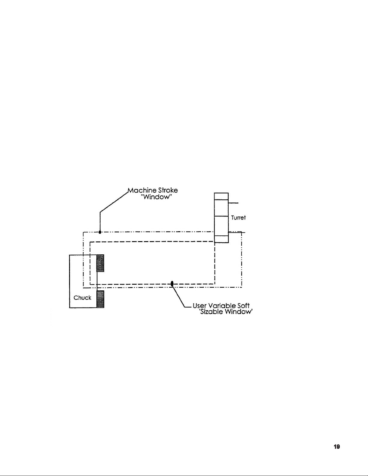
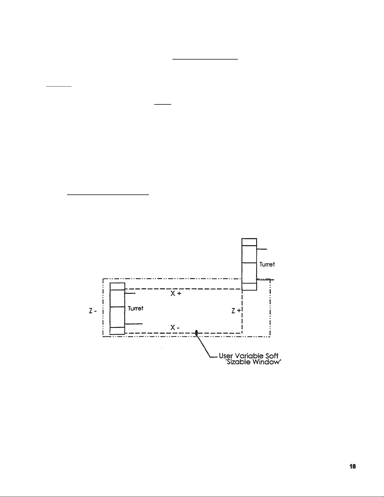
User Soft Limit / Variable Soft Limit - within the machine’s stroke end limits, it is possible to
establish/dene a smaller ‘window’ used to dene a smaller working range. The boundaries of
this smaller window are called user soft limits.
The primary reason to establish a ‘soft limit’ is to reduce the distance the turret has to travel
in order to ‘be at a limit’ and receive the conrmation signal, so that a turret index command
may be executed.
The machine’s turret will not index until either the ‘X’ positive, or ‘Z’ positive
limit condition is satised .
The following illustration depicts the ‘working range’ within which the turret can travel, based on those ‘soft
limits’ that have been dened in the OSP control.
Note: In the above illustration, the ‘chuck’ is not shown for reasons of clarity.
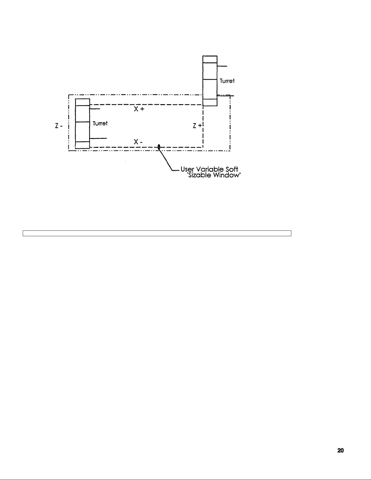
To make the turret travel to its [X+, Z+} limit, the user should use the following command:
G00 X50 Z50
This command will position the turret to the current soft limits, which may or may not
be representative of the machine’s maximum stroke end travel.
Notes:
1. Positioning the turret to the “limits” cannot be performed by using a G01
command.
2. The user must select a ‘X’ and ‘Z’ value that will always exceed the machine’s working range.
A general rule of thumb is to double the actual axis stroke amounts. Using X50, Z50 will
sufce for the majority of instances, except for those machines with considerable bed length.

Problems
1) If your part has a program zero at the front of the part, explain why the Zs in the program have
a negative sign in front of the numbers?
2) What is meant by soft limits?
3) Where is the turret home position?
4) How do you know if the turret slide is at a slide limit?
5) What is meant by the positive stroke end limit?
6) Also, what can you do with the turret when it reaches that limit?
7) What is the line code that will allow you to index the turret?

OPERATION
Basic Construction of Operation Panels
For operating the machine, the following four kinds of man-machine interfaces are provided:
(1) NC Operation Panel
It is used for le operation and data setting.
(2) Machine Operation Panel
These switches and keys used mainly for manual operation. They are located in the
controls operation panel.
(3) Option Panel
An option panel is provided, which contains switches and indicating lamps required for
user specied options. Arrangements of the switches and indicating lamps differ
depending on the selected optional specication.
(4) Foot Pedal (Foot Switch)
A foot pedal is provided to control chuck open/close and tail stock spindle advance/
retract.
Various types of operator panels are included, depending on the shape of
the panel and the arrangement of the controls. External views of the operator panels
are provided in the Appendix of this manual.

Outline of Controls on Operation Panel
Operation Mode Selection Keys
(1) AUTO Key
Select the automatic mode when operating the machine using
a stored part program.
(2) MDI Key
Select the MDI mode for block operation, permitting input of the data
necessary for operation by the keyboard in the NC operation
panel.
(3) MANUAL Key
Selects the manual mode for operator by the switches on the machine
operation panel.
Data Setting Mode Selection Keys
(1) EDIT AUX. Key
Selects the program operation mode for operating program les and
data les. In this program operation mode, it is possilbe to edit input/
output, display or delete a program le.
(2) PARAMETER Key
Selects the parameter mode for setting, changing or displaying
parameter data necessary for NC control.
(3) ZERO SET Key
Selects the zero set mode for setting, changing, or checking the
zero offset data and zero shift data which dene a program coordinate system.
(4) TOOL DATA
Selects the tool data mode for setting, changing, or displaying the
tool offset data, nose R compensation data, tool shape data, and load monitor data.
(5) MacMan
Selects the MacMan (machining management function).

NC Status Indicating lamps
(1) RUN Lamp
The RUN lamp 15 on when the machine is operation in the
automatic or MDI mode.
(2) S.T.M Lamp
The S.T.M. indicating lamp is on while auxiliary function operation
such as spindle gear range change, tool change, and spindle rotation, is executed.
When an axis movement command is designated with an S, T, and /or M command,
the axis movement command is executed after the completion of the S, T, and /or M
command designated in the same block.
If a spindle gear range command, spindle speed command, or tool number command
is changed using the manual intervention function (called out by pressing the [MID
AUTO MANUAL] key), the S.T.M. indicating lamp blinks.
(3) SLIDE HOLD Lamp
The SLIDE HOLD indicating lamp is on when the [SLIDE HOLD]
button is pressed in the automatic or MDI mode.
For the two-saddle option, it also goes on if the operation of either of
the two saddles enters the slide hold state with the other saddle having
completed single block mode operation in the automatic mode.
(4) PROGRAM STOP Lamp
The PROGRAM STOP indicating lamp is on during the execution of
a program stop (M00) or optional stop (M01) function in the automatic
or MDI mode.
The indication lamp blinks during the execution of a dwell (G04) function.
(5) LIMIT Lamp
The LIMIT indicating lamp is on when either X- or Z - axis reaches
its limit position.
For the two-saddle option, the indicating lamp is on if any of XA, ZA-,
XB-, and ZB - axis reaches the limit.
The indicating lamp blinks if the actual spindle speed reaches the maximum or
minimum speed of the selected gear range, or when it reaches the spindle speed
specied using the maximum spindle speed specication function.

(6) ALARM Lamp
The ALARM indicating lamp is on when the machine malfunctions or
an incorrect program is input. It is also on if the computer
fails to function correctly.

Status Indicating
Lamp
RUN - The machine is normally running in
S.T.M -The machine is waiting for the
Condition for ON Condition for Blinking
the AUTO or MDI mode
(except for during the SLIDE HOLD
and PROGRAM STOP mode).
operation completion of an M code
command. (Spindle rotation command, gear command, etc.).
- A spindle speed command is given
(S command).
- A turret rotation command is given
(T command).
Only for the multi-machinig options:
-The program selection command is a
schedule program is being executed.
-The following items have been
changed during manual intervention.
Tool number
Spindle rotation/gear command
Only for the multi-machining specication
-The machine is waiting for the
operation completion of a multi-machining M code command.
(C-axis joint command , M-tool
spindle rotation command, etc.).
-An M-tool spindle speed command
is given (SB command).
-The C-axis brake pressure is
switched between high and low.
Only for the ATC specication
- The machine is waiting for the operation completion of the MG, MT or
TN command.
SLIDE HOLD -The SLIDE HOLD button has been
pressed in the AUTO or MDI mode.
C- axis joint state
C-axis clamp
M-tool spindle ratation/gear
command
Does not blink.
-A block of program commands
has been executed on one saddle
while the other saddle is placed in
the slide hold mode with the single
block function activated in the AUTO
mode.
PROGRAM STOP -M00 OR M01 is designated in the
AUTO or MDI mode.
-The dwell command (G04) is executed.

Status In dicating
Lamp
LIMIT -Either X- or Z -axis has reached
ALARM -Any erroneous operation is at-
Condition for ON Condition for Blinking
the variable soft-limit position.
tempted (An alarm of level A, B,
C, or D).
-The spindle speed has reached the limit in
the selected gear range.
-The spindle speed has reached the limit
specied by the maximum spindle speed
designation function.
-The spindle position is controlled after the
completion of spindle orientation (DIFF
control).
-The M-tool spindle position is controlled
after the completion of spindle orientation.
Does not blink.
Other Controls on NC Operation Panel
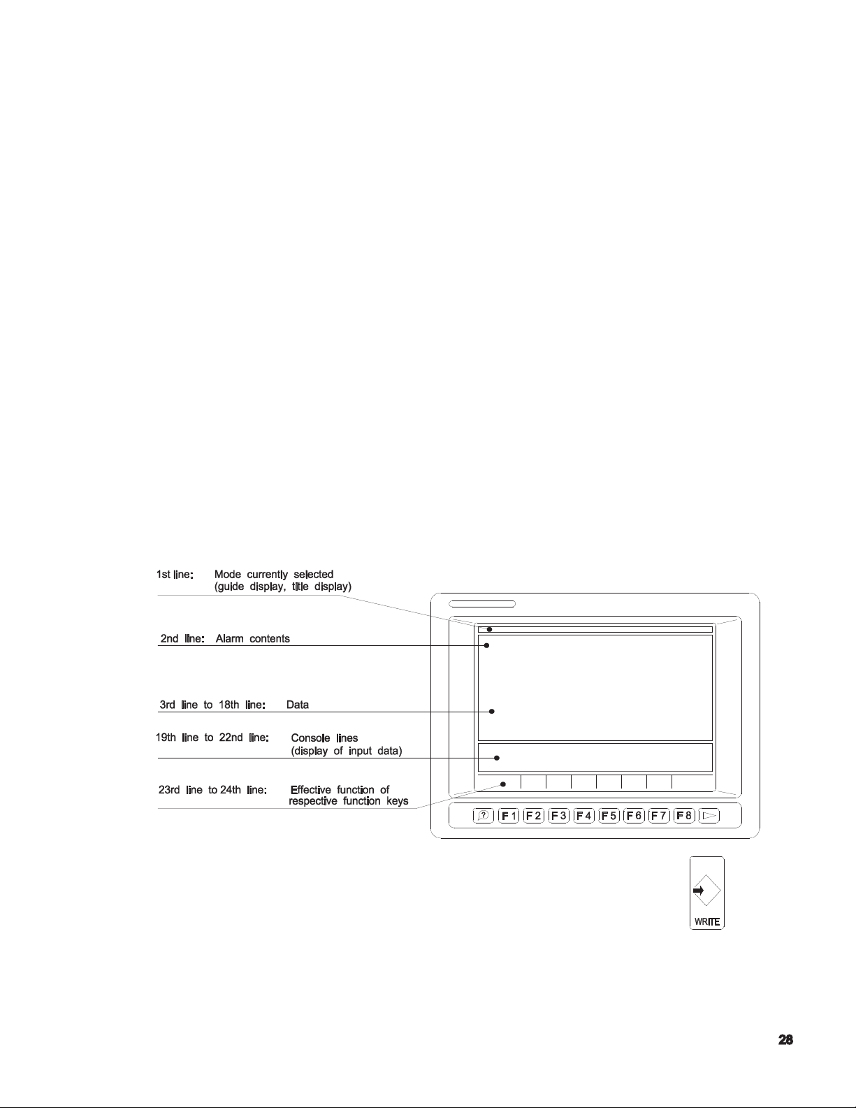
(1) Function Keys: F1 to F8
There are eight function keys on the NC operation panel.
When an operator selects a desired operation mode, the screen displays the T
operation functions at the bottom line. Each function corresponds to a function key
(F1 through F8). Select the function to execute and press the corresponding function key.
If all functions called out by the selection of a mode cannot all be displayed
simultaneously, the ([EXTEND]) message is displayed for function key [F8]. In this case,
press [F8] to display the rest of functions.
[F1] [F2] [F3] [F4] [F5] [F6] [F7] [F8]
(2) ? (Help) Key
This key is used to display the description of the alarm which occurred during machine
operation and also the alarm history.
It shows actual position data, part program data, block data, zero offset values, tool
offset values, parameter data, alarm description, etc.
The basic format of display on the scree
(3) WRITE Key
n is shown below.
The [WRITE} key to select an operation and also conrms
input data.
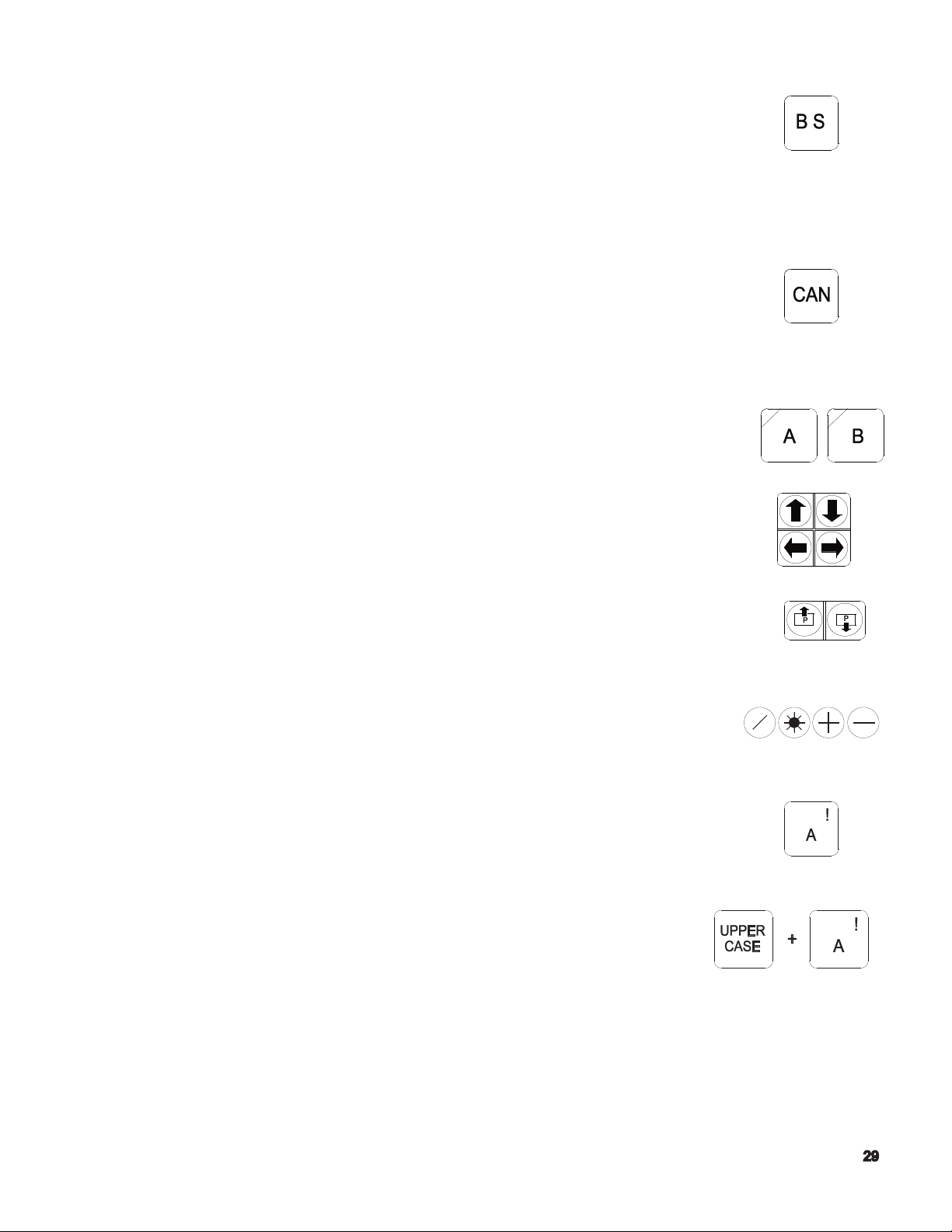
(4) BS (Backspace) Key
The [BS] key is used when erroneous data has been input.
Each time this key is pressed, the character input last is erased.
For the display of le index and list, this key is used to display the next
page.
(5) CAN Key
The [CAN] key is used when erroneous data has been input.
Each time this key is pressed, one line of the data is erased.
(6) Turret Selection (AB) Keys
These keys are used to select the appropriate turret or saddle
(A saddle side, B saddle side) for NC control of the two-saddle
or two-turret models.
(7) Cursor Keys
Four cursor keys are used to move the cursor displayed
on the screen.
(8) Page keys
If the information called out is displayed in more than one
page, the page keys are used to change the display page.
(9) Operator Keys
These keys are used when an operator edits a program or enters data.
(10) Character Keys
Character keys are used for inputting a character for data
input, program operation, and le edit operation.
(a) To input a character shown at the upper right
corner of a key top, use the [UPPER CASE] key.

(b) When the [CAPS LOCK] key is pressed
(indicating lamp at the upper left corner lit), upper
case alphabetic letters A to Z are input. When the [CAPS LOCK]
key is not pressed, lower case alphabetic letters a to z are input.
(11) Numerical Key Pad.
These keys are used for inputting numbers for data input,
program operation, and le edit operation.
(12) Contrast Adjusting Keys
(only for Operation Panel with Monochrome STN Screen)
These keys are used to adjust the contrast for the display.
Controls on Machine Operation Panel
Flat keys used on the machine operation panel have features as indicated
below depending on whether or not they have an indicator lamp.
< Flat keys with an indicating lamp >
The indicating lamp in a key indicates if the function of the key
is valid or not.
- Indicating lamp lit . . . . . . . . . Key function is valid.
- Indicating lamp unlit . . . . . . Key function is invalid.
< Flat keys without an indicating lamp >
The function of the key is valid only while the key is
held down. If the key is not pressed, the function is invalid.
(1) CONTROL ON Switch
The [CONTROL ON] switch is used to turn on the
control power of the NC unit after turning on the main switch of the machine.
The pilot lamp in this switch lights when the control power is turned on.
If the [EMERGENCY STOP] button is pressed, the pilot lamp in this
switch goes off. To leave the emergency stop state, press the
[CONTROL ON] switch.
 Loading...