


okuma MAC 350 Maintenance Manual

MACTURN 350
MACTURN 350-W
OPERATION & MAINTENANCE
(1st Edition)
Pub No. 6097-E (LE11-240-R1) Oct. 2012

6097-E P-(i)
SAFETY PRECAUTIONS
SAFETY PRECAUTIONS
The machine is equipped with safety devices which serve to protect personnel and the machine itself from
hazards arising from unforeseen accidents. However, operators must not rely exclusively on these safety
devices: they must also become fully familiar with the safety guidelines presented below to ensure accidentfree operation.
This instruction manual and the warning signs attached to the machine cover only those hazards which
Okuma can predict. Be aware that they do not cover all possible hazards.
1. Moving and Installing the Machine
• There are three methods of moving the machine to any desired location; lifting the machine
using the attached lifting hooks, pushing the machine on rollers, and moving with a forklift
truck. Perform any of them with following precautions below.
Precautions for Lifting:
a. Use the wire rope of 24 mm (0.94 in.) or over in diameter.
b. Check the wire rope angles so that the ropes do not interfere with the machine.
(Do not slant the machine more than 40 degrees from the vertical.)
c. Lift the machine carefully while balancing the machine.
d. When placing the machine on the floor, lower the machine slowly using care not to give
shocks to the machine.
Approximate Machine Mass
13,700 kg (30,140 lb) (44-tool magazine)
(Machine weight including hydraulic unit, control cabinet, NC unit, and tool magazine)
Precautions for Rolling
a. Do not tip over or hit the machine against the ground.
Notes on forklift :
a. Watch the lower surface of the machine when you move it by forklift and treat with care so
as not to damage the jack bolts or rotary joints with the forklift forks.
The machine may come out of the bottom surface of the bed, depending on its
specification.
LE11240R0100100020001

6097-E P-(ii)
SAFETY PRECAUTIONS
• When selecting the machine installation site, ensure that the following conditions are met.
If not, it may be difficult to perform safe operation or maintain the guaranteed accuracy.
a. The machine ambient temperature is within the range from 5 to 40°C (41 to 104°F).
b. The machine ambient humidity is within the range from 40 to 75% at 20°C and no
condensation is allowed.
c. Avoid installation near the factory door because the machine is subject to rapid
temperature change by warm or cool air blowing against the machine.
d. Also avoid installation in a place which is subject to direct sunlight.
e. For the installation ground conditions, refer to Section 2 “Transportation and Installation
(Relocation).”
f. To maintain the guaranteed accuracy, you are advised to care and control the factory
temperature.
Recommended temperature change for 24 hours: : Within ±2°C (36°F)
Temperature difference between the measurement near
the floor and the measurement at a position 3 m (10 ft.)
high from the floor
: Within 1°C (34°F)
2. Before Turning on the Power
• Make sure that the doors to the operation panel and the electric control cabinet are closed.
• Make sure that there are no obstacles around the machine.
• Turn on the main power disconnect switch before turning on the CONTROL on the operation
panel.

3. Chuck Precautions
• Always close the front shield before starting the spindle or cutting operations.
• Always observe the spindle speed maximums for the installed chuck.
Never run the spindle exceeding the maximum allowable chuck speed.
• If a chuck or fixture is unique to your application, check the maximum allowable spindle speed
and stay within the limit. Also, take note of the workpiece gripping force and balance.
• The maximum spindle speed can be limited by inputting a G50 command with the spindle
speed. The G50 command helps to ensure safety in operation.
• If the spindle must be rotated close to the maximum allowable chuck speed, observe the
following points:
The maximum allowable spindle speed and application pressure are indicated on the name
plate on the front shield and on the chuck body. The allowable maximum speed and the
applicable pressure ensure a chucking force that is more than one-third of the original chuck
gripping force with the standard soft-top jaw set in line with the periphery of the chuck body.
a. Make sure that the workpiece clamped in the chuck is balanced.
6097-E P-(iii)
SAFETY PRECAUTIONS
b. Apply the allowable maximum amount of pressure to grip the workpiece because
centrifugal force reduces the chuck gripping force.
• If special jaws (larger than standard soft-top jaws) are used, observe the following points:
a. Lower the spindle speed because centrifugal force and lower efficiency reduce the chuck
gripping force.
b. If the jaw tightening nut (jaw nut) is outside of the periphery of the chuck, only one
tightening bolt is holding the jaws in place. This is a potentially dangerous condition. Jaw
nuts must always be within the periphery of the chuck.
c. Machine the jaws to the workpiece shape.
• Securely tighten the bolts on the chuck body, the jaws, and the block to the specified torque.
Use lubrication oil. Make sure that the torque is at least 392 to 490 N (88 to 110 lbf).

4. General Checks
• Check the amount of lubricating oil every day before starting operation.
• Always use the specified brand of lubricating oil.
• Use the recommended type of cutting fluid (coolant) when possible.
• It is recommended to use a water-soluble coolant to prevent fire. Do not attempt unmanned
operation if a non-soluble coolant is used.
• Change and replenish the lubricating oil and coolant in each reservoir according to the
schedules in the manual.
• Clean the filters according to the schedules in the manual.
• Make sure that each pressure gauge on the air and hydraulic lines display the correct value as
described in this manual.
• Always turn off the power before beginning any work inside the front shield. In addition, turn off
the power before beginning work at the back of the machine that requires an operator to enter
the machine operating zone.
6097-E P-(iv)
SAFETY PRECAUTIONS

5. Before Starting Operation
• Always follow the instructions in the operation manual.
• Always make sure that all of the protective covers including the front door and the chuck cover
are in place before operating the machine.
• Always close the front shield before starting operation.
• Never attempt to run a new program without checking its operation. Run the program without a
workpiece set in the chuck and make sure that there is no interference. After making sure that
the program has no bugs, cut a workpiece in the single block mode. If no problems are
discovered, automatic operation may be started.
• Before attempting the following operations, make sure that they can be accomplished safety.
a. Spindle rotation
b. Turret indexing
c. Axis movement
6097-E P-(v)
SAFETY PRECAUTIONS
• Never touch chips or the workpiece while the spindle is rotating.
• Never attempt to stop a moving object by hand or with a tool.
• Check the jaw installation conditions, the hydraulic pressure, and the maximum allowable
spindle speed for the power chuck.
• Check the installation and arrangement of the tools.
• Check the tool offset settings.
• Check the zero offset settings.
• Make sure that the spindle speed and feedrate override settings are at 100%.
• Before feeding the turret, check the software limit setting position for both the X- and Z- axes.
• Check the turret index/rotation position.
• Check the tailstock body position.
• Make sure the cutting operation is within the allowable transmission power and torque ranges.
• Make sure that the workpiece securely fitted in the chuck or fixture.
• Check the cutting fluid nozzle positions. They must be set to properly supply cutting fluid to the
appropriate points.

6. Precautions against Fire
• Selecting Coolant
Use nonflammable coolant.
a. Never use oil coolant because it could catch fire from heated chips, tool’s frictional heat, or
grinding spark.
When using oil coolant for unavoidable reason, observe the following:
a. Check the tool edge condition, tool life, and set the cutting conditions that never cause fire
before you start machining.
b. Clean the coolant filter at regular intervals to maintain sufficient coolant discharge, and
always check the coolant for normal discharge.
c. Take every measures so that you can extinguish the fire immediately by placing a fire
extinguisher near the machine and have an operator always watch the machining
condition, or installing an auto extinguisher.
d. Do not place any flammable objects near the machine.
6097-E P-(vi)
SAFETY PRECAUTIONS
e. Dispose of chips not to allow them to stack.
f. Periodically clean the inside and surrounding of the machine while checking that all the
devices are normally operating.
g. Never attempt untended operation.
h. When using oil coolant for grinding, you are requested to install fire-fighting equipment
such as auto extinguisher. In this case, inform us of your intention in the stage of
examining your facility.
• When machining flammable material
a. Before machining any of the flammable solid materials such as resin, rubber, or wood,
carefully study and understand the material characteristics and observe the above
precautions to take all possible measures to prevent fire.
b. Use particular care when machining magnesium, because its chips react to the water-
soluble coolant and generate hydrogen. The hydrogen may catch fire from burnt chips,
resulting in explosive fire.
• Performing Dry Machining
a. Dry machining is a fire hazard because workpiece, tool, or chips are not cooled. Therefore,
never place any flammable objects near the machine and dispose of chips not to allow
them to stack.
b. Take the same safety measures as in the case of using oil coolant described above, such
as checking the tool edge state and tool life, and setting cutting conditions that never cause
fire.
• Emergency Measures in Door-close and Power-OFF State
a. Should fire break out in the machine when the door is closed and the power is OFF, open
the door using the door lock switch release key and extinguish the fire.
(For details, refer to “Safety door switch” in SECTION 3. 3-2-11. Interlock.)

7. Setup
• Make sure that setup is complete.
• If the setup is changed, operate the machine step-by-step to make sure that cutting can be
performed without any problems.
• Before changing the chuck and/or chuck jaws, make sure that the chuck fits the intended job.
• If two or more workers must work together, establish signals so that they can communicate (for
example, when lifting or setting heavy objects). Each worker should be aware when a new
process is about to begin.
• Use a crane or equivalent tool to handle heavy objects.
• When attempting an unfamiliar setup, recheck the setup before beginning operation.
• Remove unnecessary toolholders from the turret.
• Ensure that the bolts for fixing the toolholders to the turret are securely tightened.
• Remove the bolts which are not used for fixing the toolholders.
6097-E P-(vii)
SAFETY PRECAUTIONS
8. Workpiece Loading and Unloading
• Make sure that workpieces are loaded and unloaded securely.
• Before loading or unloading a workpiece, retract the turret so that the cutting tools in the turret
cannot injure the operator.
• Before loading and unloading a workpiece, make sure that the spindle has come to a complete
stop.
• Before running a new program, rotate the spindle to make sure that the workpiece is securely
clamped in the chuck.
• Before machining an irregularly-shaped workpiece, make sure that it is balanced properly.
• When handling heavy workpieces, use a crane, hoist, or other similar tool.
• Before loading a workpiece, make sure that the workpiece has a portion that can be used for
proper chucking.
9. At the End of the Day
• Clean the machine.
• Move the turret to the predetermined retraction position.
• Turn off the CONTROL, before turning off the main power disconnect switch.
• Make sure all power switches are turned off.

10. When a Problem Occurs
• Stop the machine immediately by pressing the EMERGENCY STOP switch on the operation
panel.
• Consult with the person in charge of maintenance to determine what corrective measures need
to be taken.
• If two or more workers must work together, establish signals so that they can communicate (for
example, when lifting or setting heavy objects). Each worker should be aware when a new
process is about to begin.
• Only use specified replacement parts and fuses.
11. Powerful Magnet inside the Product
Some products contain powerful magnets, which could be dangerous if exposed by disassembling
the products. Those which contain powerful magnets are provided with a caution plate to indicate
where such magnets are used.
6097-E P-(viii)
SAFETY PRECAUTIONS
(1) Get assistance from Okuma for disassembling or repairing the powerful magnet housing unit.
• It is dangerous as strong magnetic attraction is exposed while/after disassembling the
strong magnetic housing unit.
• Disassembling work requires special knowledge and jigs.
(2) Danger of powerful magnet
Following are the examples of possible damage caused by being close to powerful magnet.
• Medical electronic instruments such as pacemaker produce malfunction, resulting in
serious bodily injury or loss of life.
• Implanted magnetic metal devices such as artificial eye, clip used for artery of the brain,
etc. get attracted by powerful magnet, resulting in loss of life.
• Metal clothing accessories get attracted by powerful magnet, resulting in bodily injury.
• Tools or parts get attracted by powerful magnet, resulting in bodily injury.
• Precision instrument becomes out of order.
• Magnetic memory device causes data loss.
(3) Contact Okuma when disassembling a magnet housing unit is necessary to dispose of the
machine.
12. General Precautions
• Wear appropriate clothing.
• Keep the machine and the area around it clean and organized.
• Never touch controls or switches with wet hands.

6097-E P-(ix)
SAFETY PRECAUTIONS
13. Safety Devices and Functions
Contents Location Remark
Front shield with safety glass and polycarbonate Machine
Shield open/close interlock Machine
Chuck interlock Electric control cabinet
Tailstock sleeve interlock Electric control cabinet
Tailstock sleeve position confirmation Electric control cabinet optional
Foot pedal protection cover Machine optional
Software limit Operation panel
Chuck barrier Operation panel
Turret barrier Operation panel
Tailstock barrier Operation panel optional
Emergency stop button Operation panel
Slide hold button Operation panel
Alarm display Operation panel
Short circuit breaker Electric control cabinet optional
Self-lock cylinder for chuck Machine
Cycle start requiring simultaneous depression of both buttons Machine optional
Turret rotation at low speeds (manual) Machine
Tool magazine door open/close interlock Machine
14. Symbols Used in This Manual
The following warning indications are used in this manual to draw attention to information of
particular importance. Read the instructions marked with these symbols carefully and follow them.

15. For Safe Chuck Work
• When using a chuck, refer to the instruction manual provided by the manufacture of the chuck.
And strictly observe the safety items stated in the manual.
• Set the chuck gripping force by ensuring sufficient margin of safety (2 to 3 or over). Run the
spindle within the allowable speed range set at this time.
6097-E P-(x)
SAFETY PRECAUTIONS
Centrifugal force
F0
R0
μ× (F0-f)×R0>F1×R1
F1
(Cutting force)
R1
LE11240R0100100160001
• In constant peripheral speed cutting, calculate the actual machining speed before designating
G50 (max. speed limit function).
N = (1000 × V) / (π × D
N:Spindle speed
V:Cutting speed
π:Circumference-to-diameter
ratio, 3.14
D:Machining diameter
)
LE11240R0100100160002
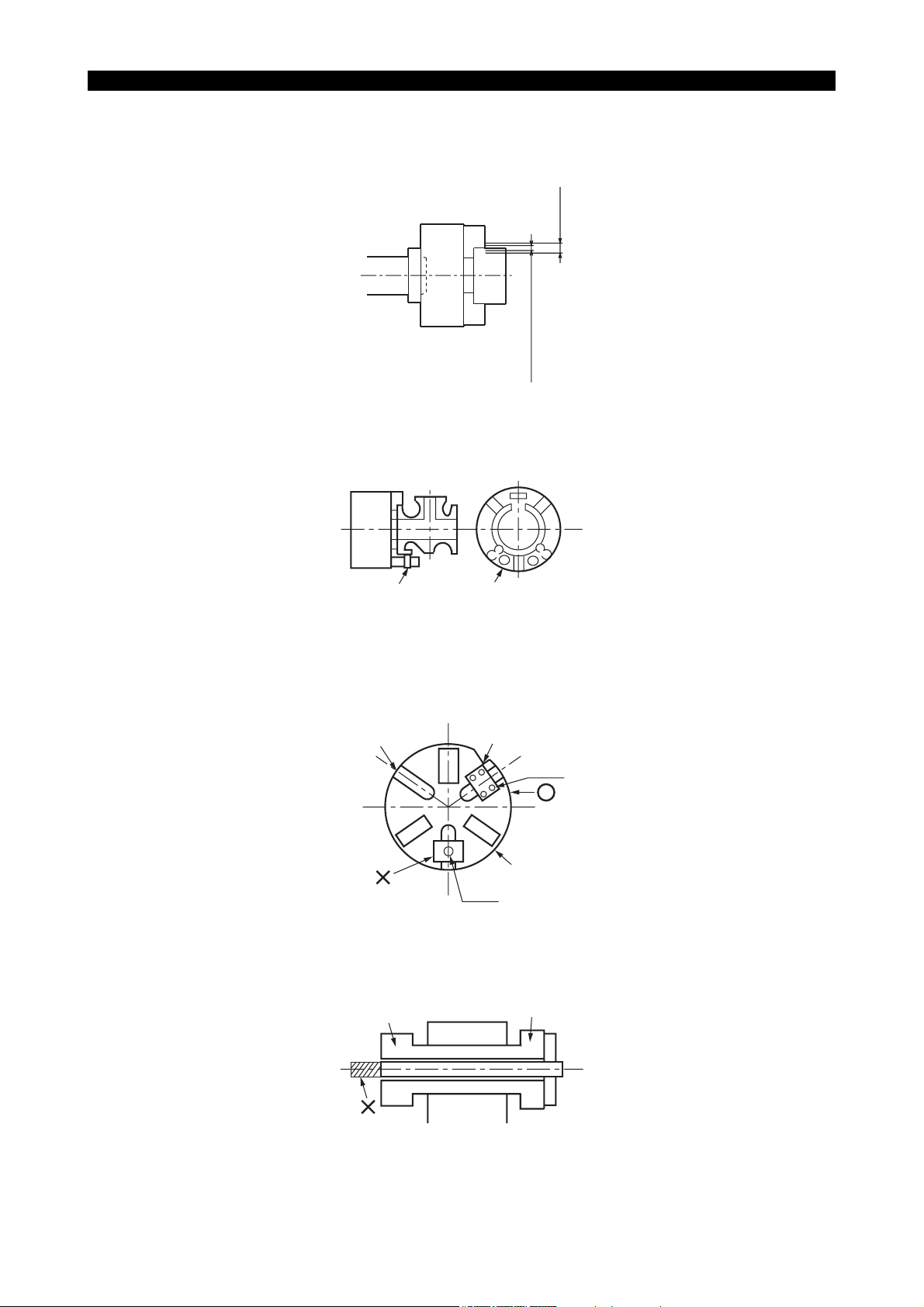
• Secure the jaw gripping depth as much as possible.
Must be
deep
LE11240R0100100160003
6097-E P-(xi)
SAFETY PRECAUTIONS
• When gripping a workpiece, soft top jaws must be at the central area of the entire jaws stroke
(see the illustration) or the base line mark on the master jaws must be located within the
appropriate chuck stroke range.
Entire stroke
Appropriate stroke range
Central one third of the entire stroke
LE11240R0100100160004
• Before machining an unbalanced workpiece, carry out balancing of the workpiece weight by
gradually changing the spindle speed.
Clamping block Balance weight
LE11240R0100100160005
• Never attempt to install jigs using T-nut.
Be sure to fix the jigs with bolts.
No chucks prepared by Okuma have T-groove.
T-slot
Jig
Bolt
Jaw
T-nut
LE11240R0100100160006
• When inserting a bar material into the hollow chuck, ensure that the bar does not protrude from
the rear end of the cylinder.
Cylinder
Hollow chuck
LE11240R0100100160007

• Never use double chucking method.
16. Caution Plate
• The machine and its components are fitted with various caution plates. Carefully read these
plates and follow the instructions described there.
• Do not tear or damage the caution plates. In case a plate has been lost or become illegible, ask
us for a new plate, quoting the Okuma part number written in this manual.
6097-E P-(xii)
SAFETY PRECAUTIONS
Chuck
Workpiece
LE11240R0100100160008
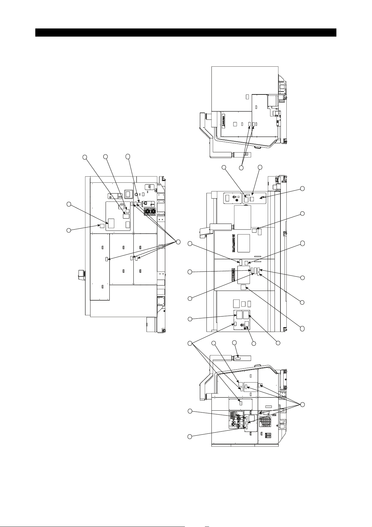
16-1. Caution Plate Positions
6097-E P-(xiii)
SAFETY PRECAUTIONS
14
16
9
13
23
4
10
10
21
19
5
1
18
17
9
22
8
7
20
10
12
11
6
15
3
2
10
LE11240R0100100180001

6097-E P-(xiv)
SAFETY PRECAUTIONS
Japanese English German Swedish Dutch
1 Warning caution H1090-1023-68-1 H1090-1164-54 H1090-1019-31-3 H1090-1029-74-3 H1044-1104-04-1
2 Instruction for oil supply to the machine body
(Model with sub spindle-OP)
3 Instruction for chuck pressure setting H1042-1173-79-3 H1044-1096-46-3 H1044-1099-06-3 H1044-1098-88-3 H1044-1103-96-2
4 Instruction for sub-chuck pressure setting (OP) H1042-1173-80-3 H1044-1096-47-4 H1044-1099-07-3 H1044-1098-89-4 H1044-1103-97-2
5 Warning H1090-1164-51-1 H1090-1164-52-1 H1090-1166-87-1 H1090-1166-88-1 H1090-1166-89-1
6 Warning against X-axis turret falling H1090-1046-45 H1090-1047-93 H1090-1048-23 H1090-1048-02 H1044-1104-08
7 Caution for cover removal H1090-1020-35 H1090-1018-33 H1090-1020-36-1 H1090-1020-37-2 H1090-1020-38-2
8 Caution for oil mist filter clogging H1090-1074-26 H1090-1074-27 H1090-1074-28-1 H1090-1074-29-1 H1090-1074-30
9 Caution for ABSOSCALE (OP) H1090-1074-33 H1090-1074-34 H1090-1074-35-1 H1090-1074-36-1 H1090-1074-37
10 Notice for ATC H1090-1019-87-1 H1090-1019-77-1 H1090-1019-82-2 H1090-1029-71-2 H1090-1074-42
11 Caution for magazine operation H1090-1039-34-3 H1090-1047-91-2 H1090-1048-21-3 H1090-1047-99-2 H1044-1104-06-2
12 Notice for touch setter (OP) H1090-1017-48-1 H1090-1024-07-1 H1090-1028-87-2 H1090-1029-96-1 H1090-1029-03-1
13 Notice for MG manual exchanging H1090-1054-39-1 H1090-1054-40-1 H1090-1054-63-2 H1090-1054-64-1 H1090-1074-43
14 Oil mist unit working pressure setting H1042-1156-74-2 H1044-1099-78 H1044-1099-82 H1044-1099-84 H1044-1104-02
15 Oil mist manifold pressure setting H1042-1156-73-2 H1044-1099-77 H1044-1099-81 H1044-1099-83-1 H1044-1104-01
16 Caution for safety glass H1090-1042-24 H1090-1041-56 H1090-1042-26-2 H1090-1042-30-2 H1090-1042-28-1
17 Caution for tool change H1090-1079-14 H1090-1079-48 H1090-1079-50-1 H1090-1080-05-1 H1090-1080-03
18 Door lock warning H1090-1050-06 H1090-1050-26 H1090-1057-69 H1090-1057-70 H1090-1057-71
19 Caution for footstep (OP) H1090-1090-62 H1090-1091-84 H1090-1091-85 H1090-1091-91 H1090-1091-94
H1090-1046-44-9 H1090-1187-47 H1090-1048-22-6 H1090-1048-01-7 H1090-1074-41-1
Danish French Italian Spanish Turkish
1 Warning caution H1090-1052-35-2 H1090-1019-23-2 H1090-1019-24-2 H1090-1032-96-2 H1090-1094-22-1
2 Instruction for oil supply to the machine body
(Model with sub spindle-OP)
3 Instruction for chuck pressure setting H1044-1101-33-3 H1044-1105-22-2 H1044-1101-79-2 H1044-1109-76-1 H1044-1115-33
4 Instruction for sub-chuck pressure setting (OP) H1044-1101-34-2 H1044-1106-22-2 H1044-1101-80-2 H1044-1109-80-1 H1044-1115-34
5 Warning H1090-1166-91-1 H1090-1166-92-1 H1090-1166-93-1 H1090-1166-94-1 H1090-1166-96-1
6 Warning against X-axis turret falling H1090-1052-79-1 H1090-1062-69 H1090-1053-72 H1090-1079-54-1 H1090-1095-91
7 Caution for cover removal H1090-1020-40-2 H1090-1018-34-1 H1090-1020-41 H1090-1024-12-1 H1090-1038-75-2
8 Caution for oil mist filter clogging H1090-1074-31-1 H1090-1062-65-1 H1090-1074-32 H1090-1079-59-1 H1090-1094-26
9 Caution for ABSOSCALE (OP) H1090-1074-38-1 H1090-1074-39 H1090-1074-40 H1090-1030-72-1 H1090-1078-95
10 Notice for ATC H1090-1019-86-2 H1090-1025-88-1 H1090-1029-83-1 H1090-1079-55 H1090-1094-27
11 Caution for magazine operation H1090-1052-34-4 H1090-1062-67-2 H1090-1053-36-2 H1090-1081-77-1 H1090-1094-28
12 Notice for touch setter (OP) H1090-1028-94-2 H1090-1028-88-1 H1090-1028-89-1 H1090-1029-63-2 H1090-1066-01-1
13 Notice for MG manual exchanging H1090-1054-65-2 H1090-1062-66-2 H1090-1054-66-1 H1090-1079-58 H1090-1095-94
14 Oil mist unit working pressure setting H1044-1101-16-1 H1044-1105-21 H1044-1101-48 H1090-1079-78-1 H1044-1115-35
15 Oil mist manifold pressure setting H1044-1101-15-1 H1044-1105-20 H1044-1101-47 H1090-1079-77-1 H1044-1115-36
16 Caution for safety glass H1090-1042-31-2 H1090-1042-27 H1090-1042-29-1 H1090-1042-25-1 H1090-1066-02-1
17 Caution for tool change H1090-1080-04-1 H1090-1079-51 H1090-1079-52 H1090-1081-79 H1090-1094-37
18 Door lock warning H1090-1057-73 H1090-1057-74 H1090-1057-75-1 H1090-1057-76 H1090-1057-41-1
19 Caution for footstep (OP) H1090-1091-90 H1090-1091-86 H1090-1091-87 H1090-1091-88 H1090-1091-93
H1090-1052-36-4 H1090-1065-76-3 H1090-1053-38-4 H1090-1079-57-1 H1090-1095-90
16-2. Caution Plates and Okuma Part Numbers
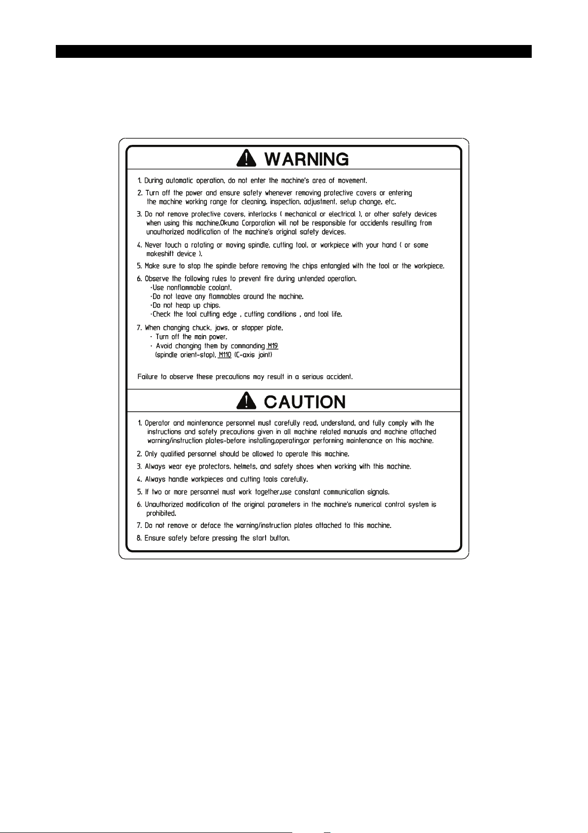
• [1] Warning caution
Okuma Part No. H1090-1164-54
6097-E P-(xv)
SAFETY PRECAUTIONS
LE11240R0100100190024

SAFETY PRECAUTIONS
• [2] Instruction for oil supply to the machine body (Model with sub spindle-OP)
Okuma Part No. H1090-1187-47
6097-E P-(xvi)
LE11240R0100100190025

• [3] Instruction for chuck pressure setting
Okuma Part No. H1044-1096-46-3
6097-E P-(xvii)
SAFETY PRECAUTIONS
• [4] Instruction for sub-chuck pressure setting (OP)
Okuma Part No. H1044-1096-47-4
LE11240R0100100190026
LE11240R0100100190027

• [5] Warning
Okuma Part No. H1090-1164-52-1
6097-E P-(xviii)
SAFETY PRECAUTIONS
• [6] Warning against X-axis turret falling
Okuma Part No. H1090-1047-93
Before removing X-axis feed servomotor for maintenance or
inspection of X-axis ball screw, servomotor or other related
parts, be sure to prevent the upper and lower turrets from
slipping down using wood blocks or the like.
Negligence of this may cause a turret to slip accidentally,
resulting in serious injury.
Example of Slip Preventive Measure
Optional
WARNING
Prop up the turrets
using wood blocks
LE11240R0100100190028
LE11240R0100100190029
• [7] Caution for cover removal
Okuma Part No. H1090-1018-33
CAUTION
ALWAYS TURN THE MAIN POWER SWITCH "OFF" BEFORE
REMOVING THIS COVER.
FAILURE TO FOLLOW THIS INSTRUCTION MAY RESULT IN
PERSONAL INJURY.
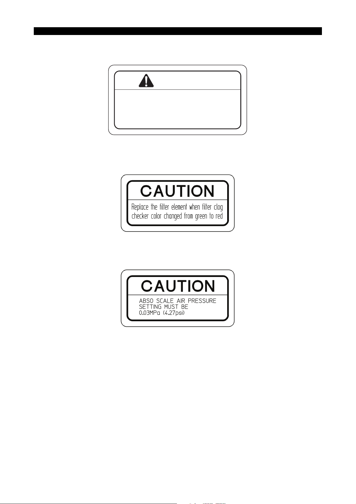
• [8] Caution for oil mist filter clogging
Okuma Part No. H1090-1074-27
6097-E P-(xix)
SAFETY PRECAUTIONS
LE11240R0100100190030
• [9] Caution for ABSOSCALE (OP)
Okuma Part No. H1090-1074-34
LE11240R0100100190031
LE11240R0100100190032
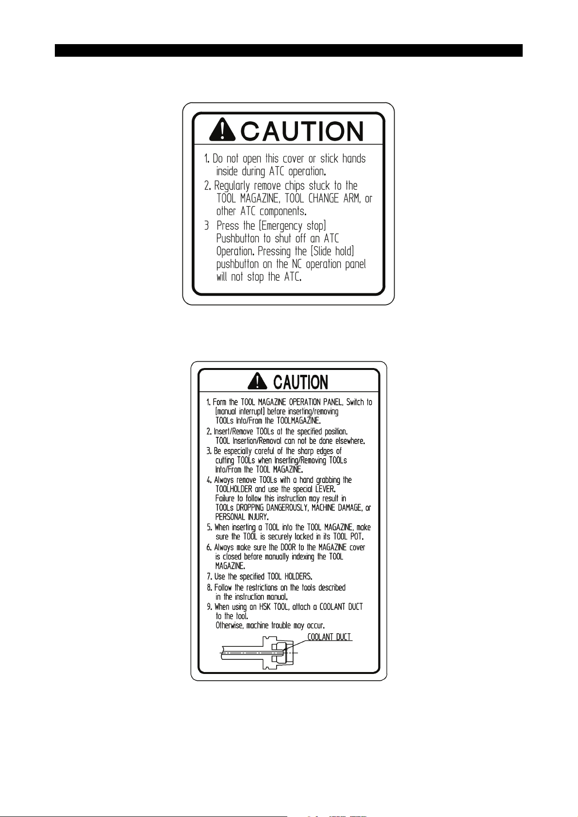
• [10] Notice for ATC
Okuma Part No. H1090-1019-77-1
6097-E P-(xx)
SAFETY PRECAUTIONS
LE11240R0100100190033
• [11] Caution for magazine operation
Okuma Part No. H1090-1047-91-2
LE11240R0100100190034
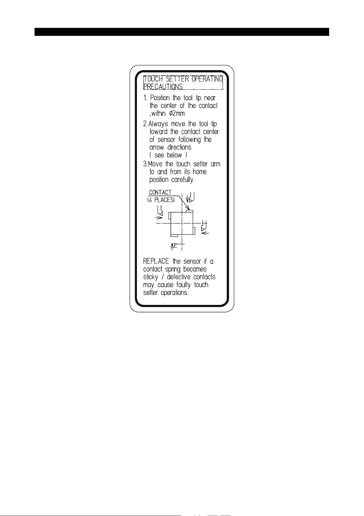
• [12] Notice for touch setter (OP)
Okuma Part No. H1090-1024-07-1
6097-E P-(xxi)
SAFETY PRECAUTIONS
LE11240R0100100190035
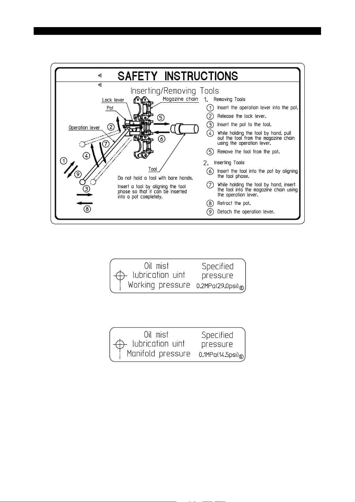
• [13] Notice for MG manual exchanging
Okuma Part No. H1090-1054-40-1
6097-E P-(xxii)
SAFETY PRECAUTIONS
• [14] Oil mist unit working pressure setting
Okuma Part No. H1044-1099-78
• [15] Oil mist manifold pressure setting
Okuma Part No. H1044-1099-77
LE11240R0100100190036
LE11240R0100100190037
LE11240R0100100190038

• [16] Caution for safety glass
Okuma Part No. H1090-1041-56
• [17] Caution for tool change
Okuma Part No. H1090-1079-48
6097-E P-(xxiii)
SAFETY PRECAUTIONS
LE11240R0100100190039
LE11240R0100100190040
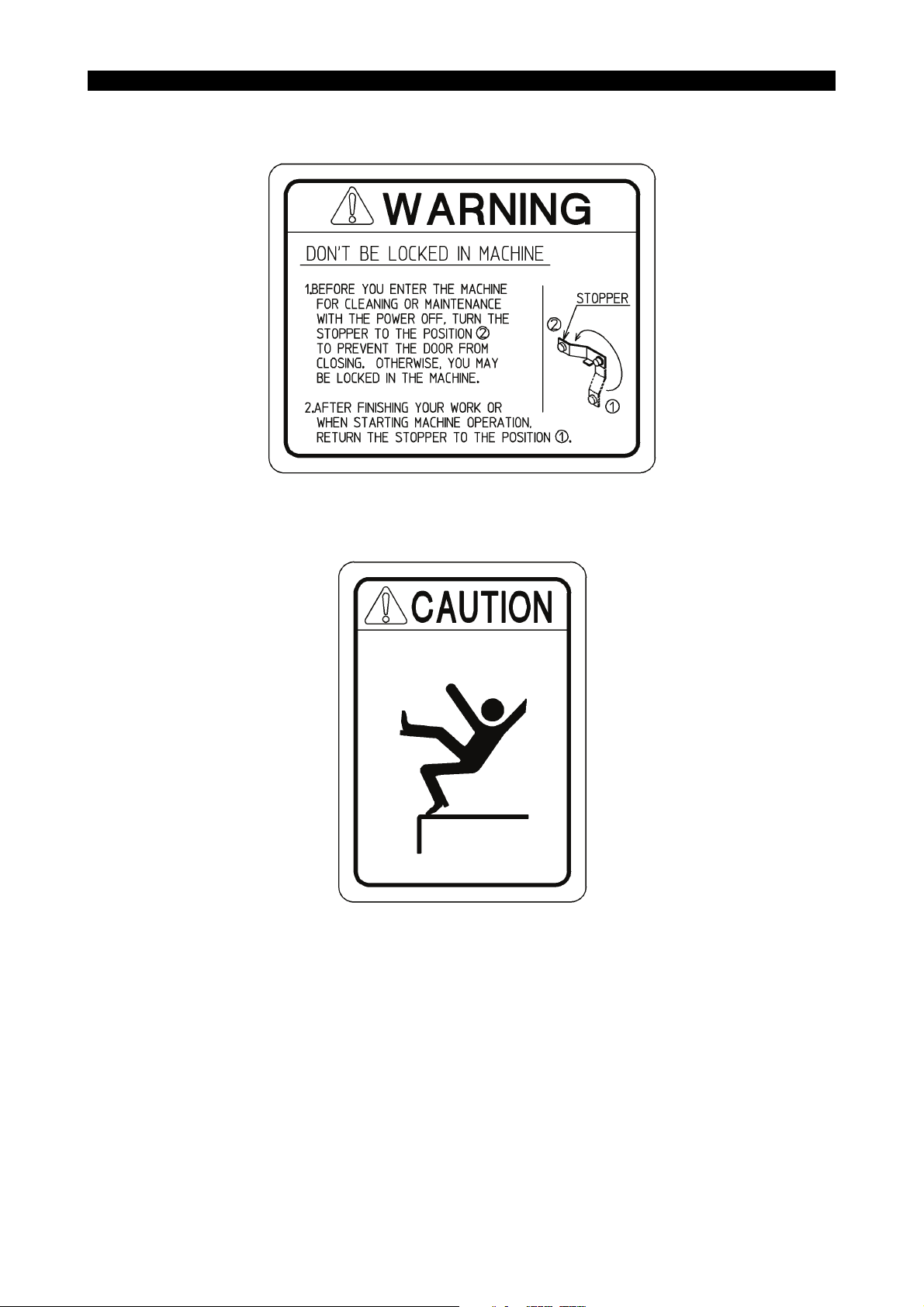
• [18] Door lock warning
Okuma Part No. H1090-1050-26
6097-E P-(xxiv)
SAFETY PRECAUTIONS
LE11240R0100100190041
• [19] Caution for footstep (OP)
Okuma Part No. H1090-1091-84
LE11240R0100100190023

6097-E P-(i)
INTRODUCTION
INTRODUCTION
This manual explains the proper handling of the machine to make the best use of its performance and the
maintenance inspection to maintain the machining accuracy for a long period of time. Carefully read this
manual and follow the instructions described there.

6097-E P-(i)
TABLE OF CONTENTS
TABLE OF CONTENTS
SECTION 1 OUTLINE...............................................................................................1
1-1. Machine Overview ............................................................................................................. 1
1-1-1. Features of Machine Components ...................................................................... 2
1-1-2. Features of Machine Functions ........................................................................... 2
1-1-3. Workpieces and Tools......................................................................................... 3
1-2. Machine Specifications ......................................................................................................4
1-2-1. Specification Table .............................................................................................. 4
1-2-2. Dimensional Drawing .......................................................................................... 7
SECTION 2 TRANSPORTATION AND INSTALLATION (RELOCATION).................8
2-1. Site Selection Guidelines...................................................................................................8
2-1-1. Water for Plant .................................................................................................... 8
2-1-2. Care in Machine Transportation .......................................................................... 8
2-2. Foundation Requirements ............................................................................................... 10
2-2-1. Safety Instructions for Foundation Work ........................................................... 10
2-3. General Procedure for Installation ................................................................................... 11
2-3-1. Installation Procedure........................................................................................ 11
2-3-2. Precautions for Installation ................................................................................ 11
2-4. Leveling the Machine....................................................................................................... 12
2-4-1. Leveling Procedure ........................................................................................... 12
2-5. Foundation Plan .............................................................................................................. 13
2-6. Power Requirements and Fuse Capacity ........................................................................ 14
2-6-1. Inspection of Cable Connection ........................................................................ 15
2-7. Oils to Be Prepared before Installation ............................................................................ 16
SECTION 3 OPERATION (OF CNC LATHE) ..........................................................17
3-1. Before Starting Operations .............................................................................................. 17
3-1-1. NC Operation .................................................................................................... 17
3-2. Machine Operation .......................................................................................................... 18
3-2-1. Axis Direction .................................................................................................... 18
3-2-2. Hydraulic Power Unit ......................................................................................... 19
3-2-3. Spindle Speed Selection (Transmission Power/Torque Diagram) .................... 23
3-2-4. Rotary Tool (M-tool) Spindle Power-Torque Diagram ....................................... 29
3-2-5. C-axis Brake...................................................................................................... 32
3-2-6. Hydraulic Power Chuck ..................................................................................... 33
3-2-7. Cutting Soft Top Jaws of Power Chuck............................................................. 45
3-2-8. Hydraulic Tailstock Operation ........................................................................... 46
3-2-9. Precautions in Handling Turret .......................................................................... 51
3-2-10. ATC ................................................................................................................... 52
3-2-11. Interlock............................................................................................................. 67

TABLE OF CONTENTS
3-2-12. After Completion of a Day’s Operation.............................................................. 68
3-2-13. Manually Operated Chuck ................................................................................. 69
SECTION 4 INSPECTION/MAINTENANCE (FOR TROUBLE-FREE
OPERATION) ......................................................................................75
4-1. Preparation of Air Source ................................................................................................ 76
4-1-1. Moisture............................................................................................................. 76
4-1-2. Filter Drain......................................................................................................... 76
4-1-3. Selecting a Compressor .................................................................................... 76
4-2. Lubrication ....................................................................................................................... 77
4-2-1. Lubricating Oil Specification .............................................................................. 79
4-2-2. Spindle Lubrication System ............................................................................... 80
4-2-3. Lubrication System for Bed/Saddle/Cross-slide Slideways ............................... 80
4-2-4. Turret ................................................................................................................. 81
4-2-5. ATC Cam Box ................................................................................................... 81
4-2-6. Maintenance and Inspection of HSK Tool Clamping Unit (HSK Tool
Specification) ..................................................................................................... 82
6097-E P-(ii)
4-3. Adjusting Centralized Lubrication Unit............................................................................. 84
4-3-1. Adjusting Pump Delivery ................................................................................... 84
4-3-2. Maintenance and Countermeasure ................................................................... 84
4-3-3. Other Remarks .................................................................................................. 85
4-4. Inspecting and Replenishing Oil Mist Lubrication Unit..................................................... 86
4-4-1. Air Flow Rate..................................................................................................... 86
4-4-2. Checking Air Pressure....................................................................................... 86
4-4-3. Replenishment .................................................................................................. 87
4-5. Lubrication and Cleaning of Spindle Cooling Unit ........................................................... 88
4-5-1. Main Spindle Cooling Unit ................................................................................. 88
4-5-2. Rotary Tool (M-tool) Spindle Cooling Unit......................................................... 90
4-5-3. Sub Spindle Cooling Unit .................................................................................. 92
4-6. Removing Sludge from Coolant Unit ............................................................................... 94
4-6-1. Procedure for Cleaning Separate Coolant Tank ............................................... 94
4-6-2. Cleaning the Filter ............................................................................................. 95
4-6-3. Cleaning the Fine Chips Collection Bucket ....................................................... 95
4-6-4. Thickener Bag Filter (Changing Procedure of Element).................................... 96
4-7. Collecting Used Lubricating Oil ....................................................................................... 97
4-8. Tensioning Belts .............................................................................................................. 98
4-8-1. Timing Belt for the XB-axis Servomotor ............................................................ 98
4-9. Adjusting the ATC............................................................................................................ 99
4-10. Other Maintenance Items .............................................................................................. 101
4-10-1. Alignment of Headstock .................................................................................. 101
4-10-2. Measures to Be Taken when Inspecting X-axis Ball Screw ............................ 102
4-11. Front Door Safety Window Glass Replacement ............................................................ 103
4-11-1. Replacement Interval ...................................................................................... 103
4-11-2. Replacement Procedure.................................................................................. 104

6097-E P-(iii)
TABLE OF CONTENTS
4-12. Troubleshooting ............................................................................................................. 111
4-12-1. Trouble with Headstock................................................................................... 111
4-12-2. Trouble with Turret .......................................................................................... 112
4-12-3. Others.............................................................................................................. 113
SECTION 5 SPARE PARTS LIST .........................................................................114
5-1. Air Unit........................................................................................................................... 114
5-2. Hydraulic Equipment ..................................................................................................... 115
5-3. Electrical Parts (Mounted in Machine)........................................................................... 116
5-4. Consumable Parts ......................................................................................................... 117
SECTION 6 TECHNICAL DATA ............................................................................121
6-1. Tooling System ..............................................................................................................121
6-1-1. BT-40 Tooling (BIG-PLUS Specifications) ...................................................... 121
6-1-2. HSK-A63 Tooling............................................................................................. 122
6-1-3. CAPTO-C6 Tooling ......................................................................................... 123
6-1-4. Tooling System (Lower Turret) ........................................................................ 124
6-2. Toolholder Dimensions .................................................................................................. 125
6-2-1. BT40 (BIG PLUS Specifications)..................................................................... 125
6-2-2. HSK Tool ......................................................................................................... 132
6-2-3. CAPTO-C6 Tool .............................................................................................. 141
6-2-4. Toolholder Dimensions (Lower Turret) ............................................................ 149
6-3. Lower Turret Tool Interference Diagram (Turret Rotation) ............................................ 154
6-4. Classification of Tools.................................................................................................... 155
6-4-1. BT40 (BIG PLUS Tooling) ............................................................................... 157
6-4-2. HSK-A63 ......................................................................................................... 160
6-4-3. CAPTO-C6 ...................................................................................................... 163
6-5. Working Ranges ............................................................................................................ 166
6-5-1. Turning Tool (BT40 BIG PLUS) [Tailstock Model]........................................... 166
6-5-2. Turning Tool (BT40 BIG PLUS) [Sub Spindle Model] ..................................... 170
6-5-3. Turning Tool (HSK-A63) [Tailstock Model]...................................................... 178
6-5-4. Turning Tool (HSK-A63) [Sub Spindle Model]................................................. 186
6-5-5. Turning Tool (CAPTO-C6) [Tailstock Model]................................................... 202
6-5-6. Turning Tool (CAPTO-C6) [Sub Spindle Model] ............................................. 210
6-5-7. Rotary Tool (BT40 BBT40-NBS20-90) ............................................................ 222
6-5-8. Rotary Tool (HSK-A63 tool A63DN-CTH20-90S06)........................................ 228
6-5-9. Turning Tool (Lower Turret) ............................................................................ 234
6-5-10. Working Ranges of Upper and Lower Turrets in Longitudinal Direction.............. 244
6-5-11. B-axis Rotation Range .................................................................................... 245
6-6. Dimensions of Spindle Nose ......................................................................................... 246
6-7. Hydraulic Power Chuck and Cylinder ............................................................................ 249
6-8. Hydraulic Circuit Diagram .............................................................................................. 252
6-9. Air Circuit Diagram ........................................................................................................ 254

6097-E P-(iv)
TABLE OF CONTENTS
6-10. Piping Drawings............................................................................................................. 255
6-10-1. Hydraulic Piping .............................................................................................. 255
6-10-2. Pneumatic Piping ............................................................................................ 265
 Loading...