


 Loading...
DRIVE UNIT
MOTIONCONTROLSYSTEM(MCS)/(MCSII)
MAINTENANCE MANUAL
(7th Edition)
Pub No. 4184-E-R6 (SE34-006-R7) Apr. 2005

4184-E P-(i)
SAFETY PRECAUTIONS
SAFETY PRECAUTIONS
The controller described in this manual consists of electric parts and units.
To prevent accidents and also failure and burning of electric parts and units due to improper interconnection of them and also connection of power cables, please read the manual carefully and strictly observe the items indicated below.
(1)Before connecting or disconnecting/removing a unit, shut off all power supplies and discharge parts in units which have been charged. Otherwise, injury, or failure or burning of a unit may occur.
(2)Check the specifications of the power supply to be connected. Failure or burning of a unit may occur if power supply voltage does not match the power requirements of the unit or if the polarity is incorrect.
(3)Connect inputs and outputs of a unit correctly. If they are connected incorrectly, failure or burning of a unit may occur.
(4)Always ground units and connect the P.E. earth cable of the electric cabinet. Otherwise, electric shock may cause if leakage occurs.
(5)Insert an over current protection device (breaker, fuse) to the power supply which is connected to units. Otherwise, cables or units may be burnt or fire may be cause due to short circuit.
(6)When manufacturing cables used for connecting units, make sure that the size of cables matches the carrying current. Especially, power cables must be manufactured carefully. If the current capacity of the cable is insufficient, the cable may be heated to be burnt or fire may be caused.
(7)The electric cabinet and the operation box where units are installed must be water-and dust-proof construction. Otherwise, injury, or failure or burning of a unit may occur.
(8)Make sure to use a thermostat incorporated in motors and units to protect devices. Otherwise, devices may be burnt or fire may be caused.

4184-E P-(ii)
SAFETY PRECAUTIONS
The following warning indications are used in this manual to draw special attention to information of particular importance.

 DANGER
indicates an imminently hazardous situation which, if not avoided, will result in death or serious injury.

 WARNING
indicates a potentially hazardous situation which, if not avoided, could result in death or serious injury.

 CAUTION
indicates a potentially hazardous situation which, if not avoided, may result in minor or moderate injury.

 CAUTION
indicates a potentially hazardous situation which, if not avoided, may result in damage to your property.
SAFETYINSTRUCTIONS
indicates general instructions for safe operation.
Keep this manual carefully so that you can read it whenever you need the information in this manual. The contents of the manual may be changed due to improvements of the product.

4184-E P-(i)
CONTENTS
CONTENTS
MIV UNIT
MIP UNIT
This book consists of several manuals and, therefore, it may contain specifications not selected for user’s machine.
Please confirm your specification by definite specifications or equivalent document.

|
|
4184-E P-(i) |
|
TABLE OF CONTENTS |
|
MIV UNIT |
|
|
SECTION 1 INVERTER UNIT (MIV UNIT) .................................................................. |
1 |
|
1. |
System Configuration .............................................................................................................. |
1 |
2. |
Classification of MIV Units ....................................................................................................... |
2 |
|
2-1. Designation of MIV Units .................................................................................................. |
2 |
|
2-2. Configuration of MIV Units................................................................................................ |
3 |
|
2-3. Construction of MIV Units................................................................................................. |
8 |
|
2-4. List of Applicable Motors ................................................................................................ |
11 |
3. |
Cautions on Changing Units .................................................................................................. |
15 |
|
3-1. General Precautions....................................................................................................... |
15 |
|
3-2. Specific Examples of Unit Replacement......................................................................... |
17 |
4. |
Indication of Operating Status ............................................................................................... |
22 |
|
4-1. Arrangement of Status Indicating LED ........................................................................... |
22 |
|
4-2. Contents of Indication..................................................................................................... |
23 |
|
4-3. Error Number Tables ...................................................................................................... |
26 |
5. |
Controller ID Number............................................................................................................. |
41 |
6. |
Description of Waveform Monitor .......................................................................................... |
44 |
|
6-1. MIV Unit for Feed Axes/Turrets/Machine Axes .............................................................. |
44 |
|
6-2. MIV Unit for Spindle/M-tool Spindle/Sub Spindle ........................................................... |
45 |
|
6-3. SWM Monitor Unit .......................................................................................................... |
47 |
7. |
Connection............................................................................................................................. |
52 |
|
7-1. System Connection ........................................................................................................ |
52 |
|
7-2. Terminal Block Screw Size............................................................................................. |
54 |
|
7-3. Connectors ..................................................................................................................... |
54 |
8. |
MIV Unit External Dimensions ............................................................................................... |
57 |
|
8-1. MIV Unit (1-axis Specification) for BL Motors................................................................. |
57 |
|
8-2. MIV Unit (2-axis Specification) for BL Motors................................................................. |
58 |
|
8-3. MIV Unit (1-axis Specification) for VAC Motors.............................................................. |
58 |
SECTION 2 DC POWER SUPPLY UNIT (MPS, MPR UNIT) .................................... |
69 |
|
1. |
System Configuration ............................................................................................................ |
69 |
2. |
Classification of DC Power Supply Units ............................................................................... |
70 |
|
2-1. Designation of DC Power Supply Units .......................................................................... |
70 |
|
2-2. Item Configuration of DC Power Supply Units................................................................ |
71 |
|
2-3. Construction of Power Supply Units ............................................................................... |
72 |
3. |
Cautions on Changing Units .................................................................................................. |
74 |
4. |
Indication of Operating Status ............................................................................................... |
76 |
|
4-1. Arrangement of Status Indicating LED ........................................................................... |
76 |
|
4-2. Contents of Indication..................................................................................................... |
77 |

|
|
4184-E P-(ii) |
|
4-3. Error Number Tables ...................................................................................................... |
78 |
5. |
Controller ID Number............................................................................................................. |
80 |
6. |
Description of Monitor Terminals ........................................................................................... |
81 |
|
6-1. Arrangement of Monitor Terminals ................................................................................. |
81 |
|
6-2. Monitor Signals............................................................................................................... |
82 |
7. |
Connection............................................................................................................................. |
83 |
|
7-1. System Connection ........................................................................................................ |
83 |
|
7-2. Terminal Block Screw Size............................................................................................. |
83 |
|
7-3. Connectors ..................................................................................................................... |
83 |
8. |
DC Power Supply Unit External Dimensions ......................................................................... |
84 |
|
8-1. MPS Unit ........................................................................................................................ |
84 |
|
8-2. MPR Unit ........................................................................................................................ |
84 |
SECTION 3 APPENDIX 1. REPLACING EXTERNAL COOLING FAN...................... |
88 |
|
1. |
Failure Diagnosis ................................................................................................................... |
88 |
2. |
Part Numbers......................................................................................................................... |
89 |
3. |
Replacement Procedure ........................................................................................................ |
90 |
|
3-1. Procedure for Replacing MIV06 to MIV22 and MPS10 to MPS30 Fan .......................... |
90 |
|
3-2. Procedure for Replacing MIV30, MIV45, MPS45 and MPS60 Fan ................................ |
92 |
|
3-3. Procedure for Replacing the Fan of the MIV01A to the MIV0404A and the |
|
|
MIV0105A to the MIV0505A ........................................................................................... |
95 |
|
3-4. Replacing the Fans of the MIV06-1 and the MIV08A-1 .................................................. |
98 |
|
3-5. Replacing the Fans of the MIV30A-3 and the MPS45A ................................................. |
99 |
4. |
Cautions............................................................................................................................... |
101 |
MIP UNIT |
|
||
SECTION 1 MIP UNIT ............................................................................................. |
102 |
||
SECTION 2 |
SYSTEM CONFIGURATION ............................................................... |
103 |
|
SECTION 3 |
MIP UNIT TYPES................................................................................. |
104 |
|
1. |
Unit Name Designation........................................................................................................ |
104 |
|
2. |
Configuration of MIP Units................................................................................................... |
104 |
|
3. |
Construction of MIP Unit...................................................................................................... |
105 |
|
4. |
Applicable Motors ................................................................................................................ |
106 |
|
SECTION 4 |
CAUTIONS ON CHANGING UNITS .................................................... |
107 |
|
SECTION 5 |
OPERATION STATUS DISPLAY.......................................................... |
108 |
|
1. Arrangement of Status Indicating LED ................................................................................ |
108 |
|
|
|
4184-E P-(iii) |
|
|
|
|
2. |
Indication of Operation Status (Inverter Control Side) ......................................................... |
109 |
|
|
2-1. Indication of Normal Operation Status.......................................................................... |
109 |
|
|
2-2. Indication of Alarm Status............................................................................................. |
110 |
|
3. |
Error Number Table (Inverter Control Side)......................................................................... |
111 |
|
|
3-1. Exception Error Number table ...................................................................................... |
111 |
|
|
3-2. |
Alarm Number Table .................................................................................................... |
113 |
|
3-3. |
Warning Number Table ................................................................................................ |
123 |
4. |
Indication of Operation Status (DC Power Supply Control Side)......................................... |
125 |
|
|
4-1. |
Indication of Normal Operation Status.......................................................................... |
125 |
|
4-2. |
Indication of Alarm Status............................................................................................. |
125 |
5. |
Error Number Table (DC Power Supply Control Side) ........................................................ |
126 |
|
SECTION 6 MONITOR TERMINALS....................................................................... |
128 |
||
1. |
Arrangement of Monitor Terminals ...................................................................................... |
128 |
|
2. |
Monitor Terminal Signals ..................................................................................................... |
129 |
|
SECTION 7 CONNECTION..................................................................................... |
131 |
||
SECTION 8 EXTERNAL VIEW OF MIP UNITS....................................................... |
135 |
||

MIV UNIT

4184-E P-1
SECTION 1 INVERTER UNIT (MIV UNIT)
SECTION 1 INVERTER UNIT (MIV UNIT)
Okuma motion control system (MCS) consists of an inverter unit and a DC power supply unit.
This section describes the maintenance and inspection methods for the inverter unit (to be referred to as MIV unit, hereafter).
1.System Configuration
MIV unit is an inverter unit that drives spindle motors and axis drive motors. Connection of MIV unit with peripheral is shown below.
•A DC power supply is connected to MIV unit to supply 300 VDC and 24 VDC (control power).
•MIV unit communicates with peripherals through the servo link, the encoder link, and the converter link.
•MIV unit has a built-in control board specially used for motor control to control a spindle motor and an axis drive motor.
•Two types of MIV unit are provided; one-axis specification which controls one motor and twoaxis specification which controls two motors.
•A DC power supply unit can be connected to more than one MIV unit.
SE34006R0700300020001
4184-E P-2
SECTION 1 INVERTER UNIT (MIV UNIT)
2.Classification of MIV Units
2-1. Designation of MIV Units
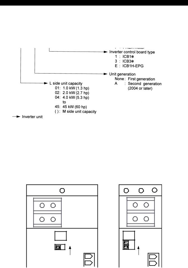
MIV unit names consist of codes indicating unit capacity, inverter control board type, motor type, and control ROM type as shown below.
SE34006R0700300030001
MIV unit type name is shown at the front of the unit either by seal or printed characters.
|
|
|
|
|
|
|
|
|
|
|
|
MIV08A-1-B5 |
M |
|
|
|
MIV0204A-1-B5 |
L |
Unit type name SR |
Unit type SR |
ST |
name |
ST |
SE34006R0700300030002
4184-E P-3
SECTION 1 INVERTER UNIT (MIV UNIT)
2-2. Configuration of MIV Units
An MIV unit comprises the unit items listed below.
2-2-1. 1-axis MIV units: Feed shaft, PLC-axis (BL motor/PREX motor)
Configuration of items of a unit set: [Control board + display card + inverter unit]
For the items of which quantity is indicated as (1) in the table below, select one unit according to your motor capacity.
Category |
Name |
Qty. |
Unit item |
Description |
|
|
ICB1-S |
(1) |
A006-2101 |
BL motor 1-axis control board (discontinued) |
|
|
|
|
|
|
|
|
ICB1S-P |
(1) |
A006-2107 |
PREX motor 1-axis control board |
|
Control board |
|
|
|
(discontinued) |
|
|
|
|
|
||
ICB1F-S |
(1) |
A006-2111 |
BL motor/PREX motor 1-axis control board |
||
|
|||||
|
|
|
|
(discontinued) |
|
|
|
|
|
|
|
|
ICB1H-S |
(1) |
A006-2121 |
BL motor/PREX motor 1-axis control board *1 |
|
|
|
|
|
|
|
Display card |
MFP1 CARD |
1 |
A006-2105 |
Card with status indicator |
|
|
|
|
|
|
|
|
MIV01-1 |
(1) |
A006-2211 |
Inverter 1-axis unit: Applicable motor capacity |
|
|
|
|
|
1.8 kW (2.4 hp) |
|
|
|
|
|
|
|
|
MIV02-1 |
(1) |
A006-2212 |
Inverter 1-axis unit: Applicable motor capacity |
|
|
|
|
|
2.8 kW (3.8 hp) |
|
|
|
|
|
|
|
|
MIV03-1 |
(1) |
A006-2213 |
Inverter 1-axis unit: Applicable motor capacity |
|
|
|
|
|
3 kW (4 hp) |
|
|
|
|
|
|
|
|
MIV04-1 |
(1) |
A006-2214 |
Inverter 1-axis unit: Applicable motor capacity |
|
|
|
|
|
4 kW (5.3 hp) |
|
|
|
|
|
|
|
|
MIV05-1 |
(1) |
A006-2215 |
Inverter 1-axis unit: Applicable motor capacity |
|
1st generation |
|
|
|
4.8 kW (6.4 hp) |
|
|
|
|
|
||
MIV06-1 |
(1) |
A006-2218 |
Inverter 1-axis unit: Applicable motor capacity |
||
inverter unit |
|||||
|
|
|
6 kW (8 hp) |
||
(discontinued) |
|
|
|
||
|
|
|
|
||
MIV08-1 |
(1) |
A006-2219 |
Inverter 1-axis unit: Applicable motor capacity |
||
|
|||||
|
|
|
|
7.5 kW (10 hp) |
|
|
|
|
|
|
|
|
MIV06DB-1 |
(1) |
A006-2265 |
Inverter 1-axis unit: Applicable motor capacity |
|
|
|
|
|
6 kW (8 hp) |
|
|
|
|
|
|
|
|
MIV08DB-1 |
(1) |
A006-2266 |
Inverter 1-axis unit: Applicable motor capacity |
|
|
|
|
|
7.5 kW (10 hp) |
|
|
|
|
|
|
|
|
MIV15-1 |
(1) |
A006-2220 |
Inverter 1-axis unit: Applicable motor capacity |
|
|
|
|
|
15 kW (20 hp) |
|
|
|
|
|
|
|
|
MIV22-1 |
(1) |
A006-2221 |
Inverter 1-axis unit: Applicable motor capacity |
|
|
|
|
|
22 kW (30 hp) |
|
|
|
|
|
|
|
DBR unit |
DBR8 |
(1) |
A006-2246 |
Dynamic brake resistor unit used for MIV06-1 |
|
|
|
|
and MIV08-1 (discontinued) |
||
|
|
|
|
||
|
|
|
|
|
|
|
|
|
4184-E P-4 |
|
|
|
|
|
SECTION 1 INVERTER UNIT (MIV UNIT) |
|
|
|
|
|
|
|
Category |
Name |
Qty. |
Unit item |
Description |
|
|
MIV01A-1 PU |
(1) |
A006-2311 |
Inverter 1-axis unit: Applicable motor capacity |
|
|
|
|
|
1.8 kW (2.4 hp) |
|
|
|
|
|
|
|
|
MIV02A-1 PU |
(1) |
A006-2312 |
Inverter 1-axis unit: Applicable motor capacity |
|
|
|
|
|
2.8 kW (3.8 hp) |
|
|
|
|
|
|
|
|
MIV04A-1 PU |
(1) |
A006-2314 |
Inverter 1-axis unit: Applicable motor capacity |
|
|
|
|
|
4 kW (5.3 hp) |
|
|
|
|
|
|
|
|
MIV05A-1 PU |
(1) |
A006-2315 |
Inverter 1-axis unit: Applicable motor capacity |
|
2nd generation |
|
|
|
4.8 kW (6.4 hp) |
|
inverter unit |
|
|
|
|
|
MIV06A-1 PU |
(1) |
A006-2318 |
Inverter 1-axis unit: Applicable motor capacity |
||
|
|
|
|
6 kW (8 hp) (under development) |
|
|
|
|
|
|
|
|
MIV08A-1 PU |
(1) |
A006-2319 |
Inverter 1-axis unit: Applicable motor capacity |
|
|
|
|
|
7.5 kW (10 hp) |
|
|
|
|
|
|
|
|
MIV15A-1 PU |
(1) |
A006-2320 |
Inverter 1-axis unit: Applicable motor capacity |
|
|
|
|
|
15 kW (20 hp) |
|
|
|
|
|
|
|
|
MIV22A-1 PU |
(1) |
A006-2321 |
Inverter 1-axis unit: Applicable motor capacity |
|
|
|
|
|
22 kW (30 hp) |
|
|
|
|
|
|
|
|
*1: The ICB1H-S is compatible with the ICB1-S, the ICB1S-P, and the ICB1F-S. |
||||

4184-E P-5
SECTION 1 INVERTER UNIT (MIV UNIT)
2-2-2. 2-axis MIV units: Feed shaft, PLC-axis (BL motor/PREX motor)
Configuration of items of a unit set: [Control board + display card + inverter unit]
For the items of which quantity is indicated as (1) in the table below, select one according to your motor capacity.
Category |
Name |
Qty. |
Unit item |
Description |
|
|
ICB1 |
(1) |
A006-2100 |
BL motor 2-axis control board (discontinued) |
|
|
|
|
|
|
|
Control board |
ICB1F |
(1) |
A006-2110 |
BL motor/PREX motor 2-axis control board |
|
|
|
|
(discontinued) |
||
|
|
|
|
||
|
|
|
|
|
|
|
ICB1H |
(1) |
A006-2120 |
BL motor/PREX motor 2-axis control board *1 |
|
|
|
|
|
|
|
Display card |
MFP1 CARD |
1 |
A006-2105 |
Card with status indicator |
|
|
|
|
|
|
|
|
MIV0101-1 |
(1) |
A006-2224 |
Inverter 2-axis unit: Applicable motor capacity |
|
|
|
|
|
1.8 kW x 1.8 kW (2.4 x 2.4 hp) |
|
|
|
|
|
|
|
|
MIV0102-1 |
(1) |
A006-2225 |
Inverter 2-axis unit: Applicable motor capacity |
|
|
|
|
|
1.8 kW x 2.8 kW (2.4 x 3.8 hp) |
|
|
|
|
|
|
|
|
MIV0202-1 |
(1) |
A006-2226 |
Inverter 2-axis unit: Applicable motor capacity |
|
|
|
|
|
2.8 kW x 2.8 kW (3.8 x 3.8 hp) |
|
|
|
|
|
|
|
|
MIV0103-1 |
(1) |
A006-2227 |
Inverter 2-axis unit: Applicable motor capacity |
|
1st generation |
|
|
|
1.8 kW x 4 kW (2.4 x 5.3 hp) |
|
|
|
|
|
||
MIV0203-1 |
(1) |
A006-2228 |
Inverter 2-axis unit: Applicable motor capacity |
||
inverter unit |
|||||
|
|
|
2.8 kW x 4 kW (3.8 x 5.3 hp) |
||
(discontinued) |
|
|
|
||
|
|
|
|
||
MIV0303-1 |
(1) |
A006-2229 |
Inverter 2-axis unit: Applicable motor capacity |
||
|
|||||
|
|
|
|
4 kW x 4 kW (5.3 x 5.3 hp) |
|
|
|
|
|
|
|
|
MIV0104-1 |
(1) |
A006-2230 |
Inverter 2-axis unit: Applicable motor capacity |
|
|
|
|
|
1.8 kW x 4 kW (2.4 x 5.3 hp) |
|
|
|
|
|
|
|
|
MIV0204-1 |
(1) |
A006-2231 |
Inverter 2-axis unit: Applicable motor capacity |
|
|
|
|
|
2.8 kW x 4 kW (3.8 x 5.3 hp) |
|
|
|
|
|
|
|
|
MIV0404-1 |
(1) |
A006-2232 |
Inverter 2-axis unit: Applicable motor capacity |
|
|
|
|
|
4 kW x 4 kW (5.3 x 5.3 hp) |
|
|
|
|
|
|
|
|
|
|
4184-E P-6 |
|
|
|
|
SECTION 1 INVERTER UNIT (MIV UNIT) |
|
|
|
|
|
Category |
Name |
Qty. |
Unit item |
Description |
|
MIV0101A-1 PU |
(1) |
A006-2324 |
Inverter 2-axis unit: Applicable motor capacity |
|
|
|
|
1.8 kW x 1.8 kW (2.4 x 2.4 hp) |
|
|
|
|
|
|
MIV0102A-1 PU |
(1) |
A006-2325 |
Inverter 2-axis unit: Applicable motor capacity |
|
|
|
|
1.8 kW x 2.8 kW (2.4 x 3.8 hp) |
|
|
|
|
|
|
MIV0202A-1 PU |
(1) |
A006-2326 |
Inverter 2-axis unit: Applicable motor capacity |
|
|
|
|
2.8 kW x 2.8 kW (3.8 x 3.8 hp) |
|
|
|
|
|
|
MIV0104A-1 PU |
(1) |
A006-2330 |
Inverter 2-axis unit: Applicable motor capacity |
|
|
|
|
1.8 kW x 4 kW (2.4 x 5.3 hp) |
|
|
|
|
|
|
MIV0204A-1 PU |
(1) |
A006-2331 |
Inverter 2-axis unit: Applicable motor capacity |
2nd generation |
|
|
|
2.8 kW x 4 kW (3.8 x 5.3 hp) |
inverter unit |
|
|
|
|
MIV0404A-1 PU |
(1) |
A006-2332 |
Inverter 2-axis unit: Applicable motor capacity |
|
|
|
|
|
4 kW x 4 kW (5.3 x 5.3 hp) |
|
|
|
|
|
|
MIV0105A-1 PU |
(1) |
A006-2333 |
Inverter 2-axis unit: Applicable motor capacity |
|
|
|
|
1.8 kW x 4.8 kW (2.4 x 6.4 hp) |
|
|
|
|
|
|
MIV0205A-1 PU |
(1) |
A006-2334 |
Inverter 2-axis unit: Applicable motor capacity |
|
|
|
|
2.8 kW x 4.8 kW (3.8 x 6.4 hp) |
|
|
|
|
|
|
MIV0405A-1 PU |
(1) |
A006-2335 |
Inverter 2-axis unit: Applicable motor capacity |
|
|
|
|
4 kW x 4.8 kW (5.3 x 6.4 hp) |
|
|
|
|
|
|
MIV0505A-1 PU |
(1) |
A006-2336 |
Inverter 2-axis unit: Applicable motor capacity |
|
|
|
|
4.8 kW x 4.8 kW (6.4 x 6.4 hp) |
|
|
|
|
|
|
|
|
*1: The ICB1H is compatible with the ICB1 and the ICB1F. |
|
2-2-3. MIV units: For spindles (VAC motor)
Configuration of items of a unit set: [Control board + display card + inverter unit]
For the items of which quantity is indicated as (1) in the table below, select one according to your motor capacity.
Category |
Name |
Qty. |
Unit item |
Description |
|
ICB3 |
1 |
A006-2102 |
VAC motor control board (discontinued) |
Control board |
|
|
|
|
ICB3F |
1 |
A006-2112 |
VAC motor control board (discontinued) |
|
|
|
|
|
|
|
ICB3H |
1 |
A006-2122 |
VAC motor control board *1 |
|
|
|
|
|
Display card |
MFP1 CARD |
1 |
A006-2105 |
Card with status indicator |
|
|
|
|
|
|
MIV04-3 PU |
(1) |
A006-2254 |
Inverter unit: Applicable motor capacity 1.1 kW (1.5 hp) |
|
|
|
|
|
|
MIV06-3 PU |
(1) |
A006-2256 |
Inverter unit: Applicable motor capacity 5.5 kW (7.5 hp) |
|
|
|
|
|
|
MIV08-3 PU |
(1) |
A006-2257 |
Inverter unit: Applicable motor capacity 7.5 kW (10 hp) |
1st generation |
|
|
|
|
MIV15-3 PU |
(1) |
A006-2258 |
Inverter unit: Applicable motor capacity 11 kW (15 hp) |
|
inverter unit |
|
|
|
|
MIV22-3 PU |
(1) |
A006-2259 |
Inverter unit: Applicable motor capacity 22 kW (30 hp) |
|
|
|
|
|
|
|
MIV30-3 PU |
(1) |
A006-2260 |
Inverter unit: Applicable motor capacity 30 kW (40 hp) |
|
|
|
|
(discontinued) |
|
|
|
|
|
|
MIV45-3 PU |
(1) |
A006-2261 |
Inverter unit: Applicable motor capacity 45 kW (60 hp) |
|
|
|
|
|
2nd generation |
MIV30A-3 PU |
(1) |
A006-2360 |
Inverter unit: Applicable motor capacity 30 kW (40 hp) |
inverter unit |
|
|
|
|
|
|
|
|
|
*1: The ICB3H is compatible with the ICB3 and the ICB3F.

4184-E P-7
SECTION 1 INVERTER UNIT (MIV UNIT)
2-2-4. MIV units: Models with a general-purpose detector interface: Feed shaft, PLCaxis (BL motor/PREX motor)
Configuration of items of a unit set: [Control board + display card + inverter unit]
For the items of which quantity is indicated as (1) in the table below, select one according to your motor capacity.
Category |
Name |
Qty. |
Unit item |
Description |
Control board |
ICB1H-EPG |
1 |
A006-2123 |
1-axis control board with a general-purpose |
|
|
|
detector interface for feed shafts/PLC-axes |
|
|
|
|
|
|
|
|
|
|
|
Display card |
MFP1 CARD |
1 |
A006-2105 |
Card with status indicator |
|
|
|
|
|
|
MIV01A-E PU |
(1) |
A006-2341 |
Inverter 1-axis unit: Applicable motor capacity |
|
|
|
|
1.8 kW (2.4 hp) |
|
|
|
|
|
|
MIV02A-E PU |
(1) |
A006-2342 |
Inverter 1-axis unit: Applicable motor capacity |
|
|
|
|
2.8 kW (3.8 hp) |
|
|
|
|
|
|
MIV04A-E PU |
(1) |
A006-2344 |
Inverter 1-axis unit: Applicable motor capacity |
|
|
|
|
4 kW (5.3 hp) |
|
|
|
|
|
|
MIV05A-E PU |
(1) |
A006-2345 |
Inverter 1-axis unit: Applicable motor capacity |
2nd generation |
|
|
|
4.8 kW (6.4 hp) |
inverter unit |
MIV06A-E PU |
(1) |
A006-2346 |
Inverter 1-axis unit: Applicable motor capacity |
|
|
|
|
6 kW (8 hp) |
|
|
|
|
|
|
MIV08A-E PU |
(1) |
A006-2347 |
Inverter 1-axis unit: Applicable motor capacity |
|
|
|
|
7.5 kW (10 hp) |
|
|
|
|
|
|
MIV15A-E PU |
(1) |
A006-2348 |
Inverter 1-axis unit: Applicable motor capacity |
|
|
|
|
15 kW (20 hp) |
|
|
|
|
|
|
MIV22A-E PU |
(1) |
A006-2349 |
Inverter 1-axis unit: Applicable motor capacity |
|
|
|
|
22 kW (30 hp) |
|
|
|
|
|
We are planning to register the inverter units as soon as they are completed. Before placing an order for any of the abovementioned unit items, confirm whether it is already registered.
4184-E P-8
SECTION 1 INVERTER UNIT (MIV UNIT)
2-3. Construction of MIV Units
Construction of MIV unit is shown below.
(1) Construction of MIV01 to MIV05-1 and MIV0101 to MIV0404-1
SE34006R0700300090001
(2) Construction of MIV06-1, MIV08-1, MIV06DB-1, MIV08DB-1, MIV06-3, MIV08-3
SE34006R0700300090002
4184-E P-9
SECTION 1 INVERTER UNIT (MIV UNIT)
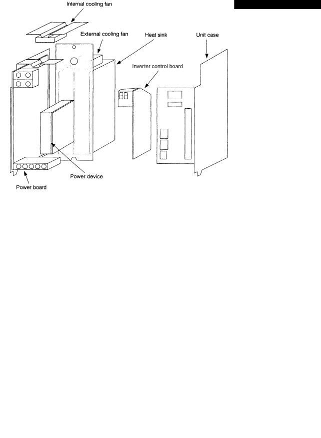
(3) Construction of MIV01A-1 to MIV05A-1, MIV0101A-1 to 0505A-1, MIV04-3
External cooling fan
Unit case
Radiation fin
Inverter control board
Power devices
Power board
SE34006R0700300090003
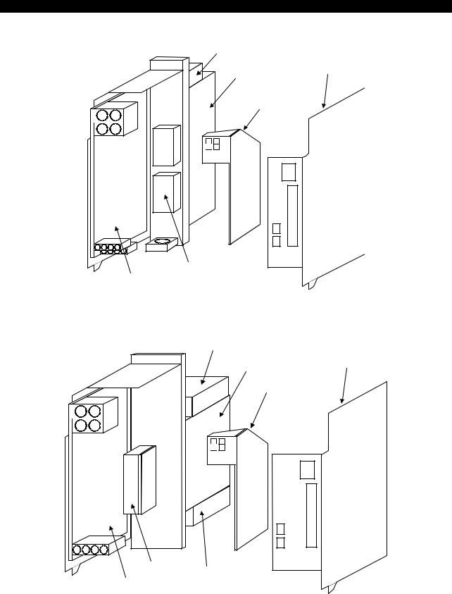
(4) Construction of MIV06A-1 to MIV08A-1
External cooling fan
Unit case
Radiation fin
Inverter control board
Power device External cooling fan
Power board |
(MIV08A-1 only) |
|
SE34006R0700300090005
4184-E P-10
SECTION 1 INVERTER UNIT (MIV UNIT)
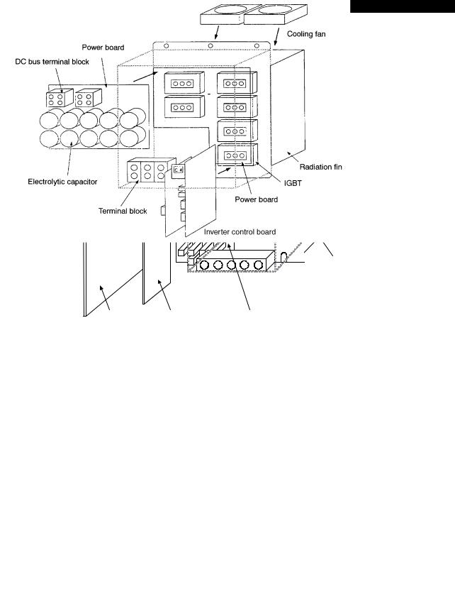
(5) Construction of MIV15A-1, MIV22A-1, MIV15-3, MIV22-3, MIV30A-3
DC bus terminal base (MIV30A-3 only)
Internal cooling fan |
External cooling fan |
|
|
|
Radiation fin |
Power module
External cooling fan (MIV30A-3 only)
Power |
Inverter control board |
Power board |
board |
|
|
SE34006R0700300090006
(6) Construction of MIV30-3 and MIV45-3
SE34006R0700300090007

4184-E P-11
SECTION 1 INVERTER UNIT (MIV UNIT)
2-4. List of Applicable Motors
2-4-1. List of applicable BL motors
For BL motor drive, 1-axis and 2-axis types are available.
The table below shows the standard combinations oft BL motor and MIV unit models. (These combinations may be changed depending on the machine specifications.)
(1) Max. torque/Rated torque = 300%
|
Motor rated |
|
MIV unit |
||
Motor model |
output |
|
|
||
1-axis type |
2-axis type *2 |
||||
|
kW (hp) |
||||
|
|
|
|||
|
|
|
|
||
BL-MC24J-30 |
0.75 (1) |
|
MIV0101-1 (L/M) |
||
|
|
|
MIV0102-1 (L) |
||
BL-MC25J-30 |
0.75 (1) |
|
|||
|
|
|
|
MIV0103-1 (L) |
|
BL-MC50J-20 |
1 (1.3) |
|
|||
MIV01-1 |
MIV0104-1 (L) |
||||
|
|
|
|||
BL-MC100J-12 |
1.2 |
(1.6) |
|||
MIV01A-1 |
MIV0101A-1 (L/M) |
||||
BL-MC50J-30 |
1.5 (2) |
|
MIV0102A-1 (L) |
||
|
|
|
MIV0104A-1 (L) |
||
BL-MC75J-20 |
1.5 (2) |
|
|||
|
|
|
|
MIV0105A-1 (L) |
|
BL-MC150J-12 |
1.8 |
(2.4) |
|
||
|
|
||||
|
|
|
|
||
BL-MC95J-20 |
2 (2.7) |
|
MIV0102-1 (M) |
||
|
|
|
MIV0202-1 (L/M) |
||
BL-MC100J-20 |
2 (2.7) |
|
|||
|
|
|
|
MIV0203-1 (L) |
|
BL-MC75J-30 |
2.2 (3) |
|
|||
MIV02-1 |
MIV0204-1 (L) |
||||
|
|
|
|||
BL-MC200J-12 |
2.4 |
(3.2) |
|||
MIV02A-1 |
MIV0102A-1 (M) |
||||
BL-MC140J-20 |
2.8 |
(3.7) |
|
MIV0202A-1 (L/M) |
|
|
|
|
|
MIV0204A-1 (L) |
|
|
|
|
|
MIV0205A-1 (L) |
|
|
|
|
|
|
|
BL-MC95J-30 |
3 |
(4) |
|
MIV0103-1 (M) |
|
|
|
|
|
MIV0203-1 (M) |
|
BL-MC100J-30 |
3 |
(4) |
|
||
|
|
|
|
MIV0303-1 (L/M) |
|
BL-MC150J-20 |
3 |
(4) |
|
||
MIV03-1 |
MIV0404-1 (L) |
||||
|
|
|
|||
|
|
|
MIV04A-1 |
MIV0104A-1 (M) |
|
|
|
|
|
MIV0204A-1 (M) |
|
|
|
|
|
MIV0404A-1 (L/M) |
|
|
|
|
|
MIV0405A-1 (L) |
|
|
|
|
|
|
|
BL-MC300J-12 |
3.6 |
(4.8) |
|
MIV0104-1 (M) |
|
|
|
|
MIV0204-1 (M) |
||
BL-MC190J-20 |
4 (5.3) |
|
|||
|
|
|
|
MIV0404-1 (L/M) |
|
BL-MC200J-20 |
4 (5.3) |
MIV04-1 |
|||
MIV0104A-1 (M) |
|||||
|
|
|
MIV04A-1 |
||
|
|
|
MIV0204A-1 (M) |
||
|
|
|
|
||
|
|
|
|
MIV0404A-1 (L/M) |
|
|
|
|
|
MIV0405A-1 (L) |
|
|
|
|
|
|
|
BL-MC140J-30 |
4.2 |
(5.6) |
|
MIV0105A-1 (M) |
|
|
|
|
MIV05-1 |
MIV0205A-1 (M) |
|
BL-MC400J-12 |
4.8 |
(6.4) |
|||
|
|
|
MIV05A-1 |
MIV0405A-1 (M) |
|
|
|
|
|
MIV0505A-1 (L/M) |
|
|
|
|
|
|
|
BL-MC300J-20 |
6 |
(8) |
MIV06DB-1 |
MIV0105A-1 (M) *1 |
|
|
|
|
MIV0205A-1 (M) *1 |
||
BL-MC400J-15 |
6 |
(8) |
|||
MIV06A-1 |
|||||
|
|
|
MIV05A-1 *1 |
MIV0405A-1 (M) *1 |
|
|
|
|
MIV0505A-1 (L/M) *1 |
||
|
|
|
|
||
|
|
|
|
|
|
|
|
|
|
4184-E P-12 |
|
|
|
SECTION 1 INVERTER UNIT (MIV UNIT) |
|
|
|
|
|
|
|
|
Motor rated |
|
MIV unit |
|
Motor model |
output |
|
|
|
1-axis type |
2-axis type *2 |
||
|
|
kW (hp) |
||
|
|
|
|
|
|
|
|
|
|
|
BL-MP400J-20 |
6.7 (9) |
MIV08DB-1 |
|
|
|
|
|
|
|
BL-MH700J-10 |
7 (9.3) |
|
|
|
MIV08A-1 |
|
||
|
|
|
|
|
|
BL-MC500J-15 |
7.5 (10) |
|
|
|
|
|
||
|
|
|
|
|
|
BL-MP300J-30 |
5.1 (6.8) |
MIV15-1 |
|
|
|
|
|
|
|
BL-MP400J-25 |
6.2 (8.3) |
|
|
|
MIV15A-1 |
|
||
|
|
|
|
|
|
BL-MP500J-20 |
7.1 (9.5) |
|
|
|
|
|
||
|
|
|
|
|
*1 Available when the carrier frequency is 5 kHz.
*2 2-axis type
The available axis names are shown in parentheses. MIV**** (L) : The L-axis of the unit is available. MIV**** (M) : The M-axis of the unit is available. MIV**** (L/M): Both the L- and M-axes are available.
|
|
|
|
|
4184-E P-13 |
|
|
|
|
SECTION 1 INVERTER UNIT (MIV UNIT) |
|
|
(2) Max. torque/Rated torque = 500% |
|
|
||
|
|
|
|
|
|
|
|
Motor rated |
|
MIV unit |
|
|
Motor model |
output |
|
|
|
|
1-axis type |
2-axis type |
|||
|
|
kW (hp) |
|||
|
|
|
|
||
|
|
|
|
|
|
|
BL-MC24J-30 |
0.75 (1) |
|
MIV0101-1 (L/M) |
|
|
|
|
|
MIV0102-1 (L) |
|
|
BL-MC25J-30 |
0.75 (1) |
|
||
|
|
|
|
|
MIV0103-1 (L) |
|
BL-MC50J-20 |
1 (1.3) |
|
||
|
MIV01-1 |
MIV0104-1 (L) |
|||
|
|
|
|
||
|
|
|
|
MIV01A-1 |
MIV0101A-1 (L/M) |
|
|
|
|
|
MIV0102A-1 (L) |
|
|
|
|
|
MIV0104A-1 (L) |
|
|
|
|
|
MIV0105A-1 (L) |
|
|
|
|
|
|
|
BL-MC100J-12 |
1.2 |
(1.6) |
|
MIV0102-1 (M) |
|
|
|
|
MIV0202-1 (L/M) |
|
|
BL-MC50J-30 |
1.5 (2) |
|
||
|
|
|
|
|
MIV0203-1 (L) |
|
BL-MC75J-20 |
1.5 (2) |
|
||
|
MIV02-1 |
MIV0204-1 (L) |
|||
|
|
|
|
||
|
|
|
|
MIV02A-1 |
MIV0102A-1 (M) |
|
|
|
|
|
MIV0202A-1 (L/M) |
|
|
|
|
|
MIV0204A-1 (L) |
|
|
|
|
|
MIV0205A-1 (L) |
|
|
|
|
|
|
|
BL-MC150J-12 |
1.8 |
(2.4) |
|
MIV0103-1 (M) |
|
|
|
|
MIV0203-1 (M) |
|
|
BL-MC95J-20 |
2 (2.7) |
|
||
|
|
|
|
|
MIV0303-1 (L/M) |
|
BL-MC100J-20 |
2 (2.7) |
|
||
|
MIV03-1 |
MIV0404-1 (L) |
|||
|
|
|
|
||
|
BL-MC75J-30 |
2.2 (3) |
|||
|
MIV04A-1 |
MIV0104A-1 (M) |
|||
|
BL-MC200J-12 |
2.4 |
(3.2) |
|
MIV0204A-1 (M) |
|
|
|
|
|
MIV0404A-1 (L/M) |
|
|
|
|
|
MIV0405A-1 (L) |
|
|
|
|
|
|
|
BL-MC140J-20 |
2.8 |
(3.7) |
|
MIV0105A-1 (M) |
|
|
|
|
|
MIV0205A-1 (M) |
|
BL-MC95J-30 |
3 |
(4) |
|
|
|
|
|
|
|
MIV0405A-1 (M) |
|
BL-MC100J-30 |
3 |
(4) |
|
|
|
MIV05-1 |
MIV0505A-1 (L/M) |
|||
|
|
|
|
||
|
BL-MC150J-20 |
3 |
(4) |
||
|
MIV05A-1 |
|
|||
|
|
|
|
|
|
|
BL-MC300J-12 |
3.6 |
(4.8) |
|
|
|
|
|
|||
|
|
|
|
|
|
|
BL-MC190J-20 |
4 (5.3) |
|
|
|
|
|
|
|
|
|
|
BL-MC200J-20 |
4 (5.3) |
|
|
|
|
|
|
|
|
|
|
BL-MC140J-30 |
4.2 |
(5.6) |
MIV08DB-1 |
|
|
BL-MC400J-12 |
4.8 |
(6.4) |
MIV08A-1 |
|
|
|
|
|
|
|
|
BL-MP400J-20 |
6.7 (9) |
MIV22-1 |
|
|
|
|
|
|
MIV22A-1 |
|
|
|
|
|
|
|
|
BL-MP300J-30 |
5.1 |
(6.8) |
*MIV22-1 |
|
|
|
|
|
|
|
|
BL-MP400J-25 |
6.2 |
(8.3) |
|
|
|
*MIV22A-1 |
|
|||
|
|
|
|
|
|
|
BL-MP500J-20 |
7.1 |
(9.5) |
|
|
|
|
|
|||
|
|
|
|
|
|
* The max torque or rated torque is 430% for these combinations only.

4184-E P-14
SECTION 1 INVERTER UNIT (MIV UNIT)
2-4-2. List of applicable VAC motors
The table below shows the standard combinations of BL motor and the MIV unit models. (These combinations may be changed depending on the machine specifications.)
Motor rated output |
MIV unit |
|
kW (hp) |
||
|
||
|
|
|
VAC 2.2 /1.1 (3/1.5) |
MIV04-3 |
|
|
|
|
VAC 3.7/2.2 (5/3) |
|
|
|
MIV06-3 |
|
VAC 5.5 /3.7 (7.5/5) |
||
|
|
|
VAC 7.5 /5.5 (10/7.5) |
|
|
|
|
|
VAC 11 /7.5 (15/10) |
MIV08-3 |
|
|
|
|
VAC 15 /11 (20/15) |
MIV15-3 |
|
|
||
VAC 18.5 /15 (24.7/20) |
||
|
||
|
|
|
VAC 22 /18.5 (30/24.7) |
MIV22-3 |
|
|
||
VAC 30 /22 (40/30) |
||
|
||
|
|
|
VAC 37 /30 (50/40) |
MIV30-3 |
|
|
MIV30A-3 |
|
|
|
|
VAC 45 /37 (60/50) |
MIV45-3 |
|
|
||
VAC 55 /45 (75/60) |
||
|
||
|
|

4184-E P-15
SECTION 1 INVERTER UNIT (MIV UNIT)
3.Cautions on Changing Units
3-1. General Precautions
The items that require special attention when changing MIV unit are indicated below.

 WARNING
MIV unit has a large-capacitance capacitor in the unit. When changing MIV unit, shut off the power and wait until the charge indicating lamp goes off. (Wait for at least 2 minutes after shutting off the power.)
(1)It is necessary to set a controller ID number after changing MIV unit. Set the controller ID number referring to 5 “Controller ID Number” in this manual or the circuit diagram after changing the MIV unit.

4184-E P-16
SECTION 1 INVERTER UNIT (MIV UNIT)
(2)Unit type of MIV units differs according to the unit capacity, the control board and the software (ROM). When changing a unit, make sure to use the unit of the same type.
SE34006R0700300120001

 WARNING
High voltage is applied to the upper and lower terminal blocks in the unit.
Do not remove the plastic terminal block cover while the power is on.
(3)The procedure for removing the plastic cover at the upper and lower terminal blocks is indicated below.
•Plastic cover at the upper terminal block
After pushing in the lock lightly, tilt the cover 10 deg. to the front and the cover can be taken out upward.
•Plastic cover at the lower terminal block
After pushing in the lock lightly, turn the cover 90 deg. then pull the cover to the front and the cover can be removed.

4184-E P-17
SECTION 1 INVERTER UNIT (MIV UNIT)
3-2. Specific Examples of Unit Replacement
Replacement of some unit models may also involve changing wiring. Specific examples of replacing such units are shown below.
3-2-1. Example of replacing an MIV unit with another MIV unit
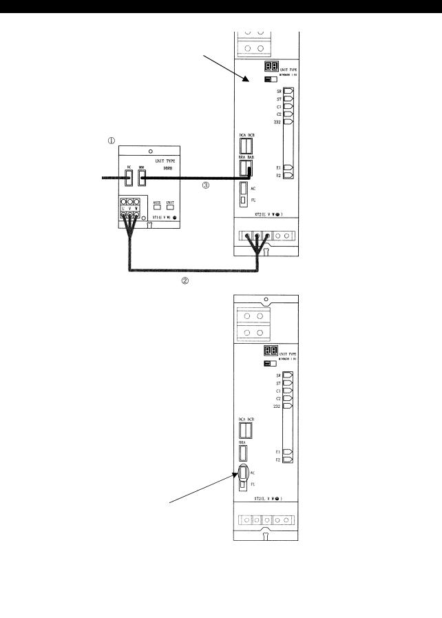
(1)Replacing the MIV06-1, MIV08-1 or DBR8
If any of the 1006-2218 (MIV06-1), 1006-2219 (MIV08-1) or 1006-2246 (DBR8) is faulty, replace the unit according to the instructions shown in the table below.
Old unit name |
|
New unit name |
Replacement procedure |
MIV06-1+DBR8 |
→ |
MIV06DB-1 |
Remove the DBR8 (see Fig. 1). |
|
|
|
|
MIV08-1+DBR8 |
→ |
MIV08DB-1 |
Remove the DBR8 (see Fig. 1). |
|
|
|
|
MIV06-1 *1 |
→ |
MIV06DB-1 |
Follow the regular unit replacement procedure. |
|
|
|
|
MIV08-1 *1 |
→ |
MIV08DB-1 |
Follow the regular unit replacement procedure. |
|
|
|
|
*1: The MIV06-1 and the MIV08-1 for PREX motors are not equipped with a DBR8.
CAUTION
Do not replace the MIV06DB-1 and the MIV08DB-1 with the units shown below.
Malfunction will result.
MIV06DB-1 → MIV06-1, MIV08DB-1 → MIV08-1
(2)Replacing the MIV14-3
Replace the MIV14-3 with the MIV15-3. This replacement work does not need the installation of software, such as servo data.
Old unit name |
|
New unit name |
MIV14-3 |
→ |
MIV15-3 |
|
|
|
(3)Replacing the MIV30-3
Replace the MIV30-3 with an MIV30-3 or MIV45-3. Replacement with an MIV45-3 does not need the installation of software, such as servo data.
Old unit name |
|
New unit name |
MIV30-3 |
→ |
MIV30-3 |
|
|
or |
|
|
MIV45-3 |
|
|
|
4184-E P-18
SECTION 1 INVERTER UNIT (MIV UNIT)
Before replacement
MIV06-1 + DBR8
Faulty!
To 24 V power supply inside the panel
After replacement
MIV06DB-1 only
What must be removed and colleted in addition to the faulty MID-06-1:
(1)DBR8 unit
(2)Cable between the DBR8 terminal block and the MIV06-1 terminal block
(3)Cable between the DBR8 connector [DBR] and the MIV06-1 connector [BRB]
(4)Cable between the DBR8 connector [DC] and the terminal block of the control box
Note) Do not fail to connect the appropriate cable to this connector.
Fig. 1 Replacing the MIV06-1 +DBR8 with an MIV06DB-1
SE34006R0700300140001

4184-E P-19
SECTION 1 INVERTER UNIT (MIV UNIT)
3-2-2. Replacing an MIV unit with an MIV-A unit
(1)Changing unit setscrew
The plate thickness may differ between MIV unit and MIV-A unit at the sect6ion fixed to the control panel. In this case, other setscrews are necessary. Refer to the Table 3-1 and prepare necessary setscrews.
Table 3-1 Control Panel Fixing Screw for MIV/MIV-A Unit
|
MIV Unit |
|
MIV-A Unit |
|
Unit Name |
Recommended Screw |
Unit Name |
Recommended Screw |
|
MIV01-1 |
|
MIV01A-1 |
M4 × 20L: E8062-330-420 |
|
|
|
|
or |
|
MIV02-1 |
|
MIV02A-1 |
||
|
|
|
M5 × 20L: E8062-330-520 |
|
MIV03-1 |
|
MIV04A-1 |
||
|
|
|||
|
|
|
||
MIV04-1 |
|
Note: |
||
|
|
|||
MIV05-1 |
|
MIV05A-1 |
M4/M5 depends on the control |
|
|
|
panel. |
||
|
|
|
||
|
|
|
|
|
MIV06DB-1 |
|
MIV06A-1 |
|
|
|
|
|
|
|
MIV08DB-1 |
|
MIV08A-1 |
Same as MIV unit |
|
|
M4 × 8L: E8062-330-408 |
|
||
MIV15-1 |
MIV15A-1 |
|||
|
||||
|
or |
|
|
|
MIV22-1 |
MIV22A-1 |
|
||
M5 × 8L: E8062-330-508 |
|
|||
|
|
|
||
MIV0101-1 |
MIV0101A-1 |
|
||
|
|
|||
|
|
|
|
|
MIV0102-1 |
Note: |
MIV0102A-1 |
|
|
MIV0202-1 |
M4/M5 depends on the control |
MIV0202A-1 |
|
|
|
panel. |
|
M4 × 20L: E8062-330-420 |
|
MIV0103-1 |
MIV0104A-1 |
|||
|
|
|
or |
|
MIV0203-1 |
|
MIV0204A-1 |
||
|
M5 × 20L: E8062-330-520 |
|||
|
|
|
||
MIV0303-1 |
|
MIV0404A-1 |
||
|
|
|||
|
|
|
Note: |
|
MIV0104-1 |
|
MIV0104A-1 |
||
|
|
with AT |
M4/M5 depends on the control |
|
|
|
|
panel. |
|
MIV0204-1 |
|
MIV0204A-1 |
||
|
|
with AT |
|
|
|
|
|
|
|
MIV0404-1 |
|
MIV0404A-1 |
|
|
|
|
with AT |
|
|
|
|
|
|
(2)Replacing the unit with the one having an attachment plate
When MIV unit was switched to MIV-A unit, the unit width was cut short for some units. To provide compatibility, attachment steel plate is added. For the units listed in the table below, the width was changed. When these units are replaced, refer to Fig. 3-1.
Table 3-2 Units with Attachment Plate for Width Adjustment
Old unit name |
New unit name |
MIV0104-1 |
MIV0104A-1 AT |
|
|
MIV0204-1 |
MIV0204A-1 AT |
|
|
MIV0404-1 |
MIV0404A-1 AT |
|
|

4184-E P-20
SECTION 1 INVERTER UNIT (MIV UNIT)
SE34006R0700300150001
4184-E P-21
SECTION 1 INVERTER UNIT (MIV UNIT)
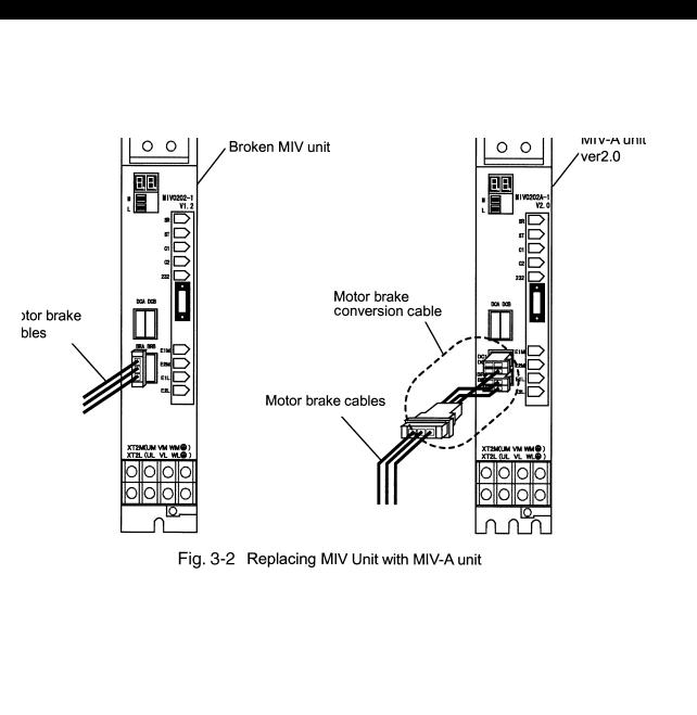
3-2-3. Replacing Motor Brake Cables
The specifications of motor brake cables have been changed in response to the replacement of an MIV unit with an MIV-A unit. Follow Fig. 3-2 to replace an MIV unit equipped with motor brake cables with an MIV-A unit.
SE34006R0700300160001

4184-E P-22
SECTION 1 INVERTER UNIT (MIV UNIT)
4.Indication of Operating Status
MIV unit shows the operating status at the 7-segment LED provided at the front of the unit. Two display modes (normal operation status display mode and alarm status display mode) are provided and at the occurrence of an alarm, the 7-segment LED displays an error number so that the cause of the alarm can be assumed.
4-1. Arrangement of Status Indicating LED
SE34006R0700300180001
Loading...