


CNC SYSTEM
OSP-P200M/P200MA/P20M
OSP-P200M-R/P200MA-R/P20M-R
PROGRAMMING MANUAL
(10th Edition)
Pub No. 5228-E-R9 (ME33-018-R10) Oct. 2010

5228-E P-(i)
SAFETY PRECAUTIONS
SAFETY PRECAUTIONS
The machine is equipped with safety devices which serve to protect personnel and the machine itself from
hazards arising from unforeseen accidents. However, operators must not rely exclusively on these safety
devices: they must also become fully familiar with the safety guidelines presented below to ensure accidentfree operation.
This instruction manual and the warning signs attached to the machine cover only those hazards which
Okuma can predict. Be aware that they do not cover all possible hazards.
1. Precautions Relating to Installation
(1) Please be noted about a primary power supply as follows.
• Do not draw the primary power supply from a distribution panel that also supplies a major
noise source (for example, an electric welder or electric discharge machine) since this
could cause malfunction of the CNC unit.
• If possible, connect the machine to a ground not used by any other equipment. If there is
no choice but to use a common ground, the other equipment must not generate a large
amount of noise (such as an electric welder or electric discharge machine).
(2) Installation Environment
Observe the following points when installing the control enclosure.
• Make sure that the CNC unit will not be subject to direct sunlight.
• Make sure that the control enclosure will not be splashed with chips, water, or oil.
• Make sure that the control enclosure and operation panel are not subject to excessive
vibrations or shock.
• The permissible ambient temperature range for the control enclosure is 5 to 40°C.
• The permissible ambient humidity range for the control enclosure is relative humidity 50%
or less at 40°C (no condensation).
• The maximum altitude at which the control enclosure can be used is 1000 m (3281ft.).
2. Points to Check before Turning on the Power
(1) Close all the doors of the control enclosure and operation panel to prevent the entry of water,
chips, and dust.
(2) Make absolutely sure that there is nobody near the moving parts of the machine, and that there
are no obstacles around the machine, before starting machine operation.
(3) When turning on the power, turn on the main power disconnect switch first, then the CONTROL
ON switch on the operation panel.

3. Precautions Relating to Operation
(1) After turning on the power, carry out inspection and adjustment in accordance with the daily
inspection procedure described in this instruction manual.
(2) Use tools whose dimensions and type are appropriate for the work undertaken and the machine
specifications. Do not use badly worn tools since they can cause accidents.
(3) Do not, for any reason, touch the spindle or tool while spindle indexing is in progress since the
spindle could rotate: this is dangerous.
(4) Check that the workpiece and tool are properly secured.
(5) Never touch a workpiece or tool while it is rotating: this is extremely dangerous.
(6) Do not remove chips by hand while machining is in progress since this is dangerous. Always
stop the machine first, then remove the chips with a brush or broom.
(7) Do not operate the machine with any of the safety devices removed. Do not operate the
machine with any of the covers removed unless it is necessary to do so.
(8) Always stop the machine before mounting or removing a tool.
5228-E P-(ii)
SAFETY PRECAUTIONS
(9) Do not approach or touch any moving part of the machine while it is operating.
(10) Do not touch any switch or button with wet hands. This is extremely dangerous.
(11) Before using any switch or button on the operation panel, check that it is the one intended.
4. Precautions Relating to the ATC
(1) The tool clamps of the magazine, spindle, etc., are designed for reliability, but it is possible that
a tool could be released and fall in the event of an unforeseen accident, exposing you to
danger: do not touch or approach the ATC mechanism during ATC operation.
(2) Always inspect and change tools in the magazine in the manual magazine interrupt mode.
(3) Remove chips adhering to the magazine at appropriate intervals since they can cause
misoperation. Do not use compressed air to remove these chips since it will only push the chips
further in.
(4) If the ATC stops during operation for some reason and it has to be inspected without turning the
power off, do not touch the ATC since it may start moving suddenly.
5. On Finishing Work
(1) On finishing work, clean the vicinity of the machine.
(2) Return the ATC, APC and other equipment to the predetermined retraction position.
(3) Always turn off the power to the machine before leaving it.
(4) To turn off the power, turn off the CONTROL ON switch on the operation panel first, then the
main power disconnect switch.

5228-E P-(iii)
SAFETY PRECAUTIONS
6. Precautions during Maintenance Inspection and When Trouble Occurs
In order to prevent unforeseen accidents, damage to the machine, etc., it is essential to observe the
following points when performing maintenance inspections or during checking when trouble has
occurred.
(1) When trouble occurs, press the emergency stop button on the operation panel to stop the
machine.
(2) Consult the person responsible for maintenance to determine what corrective measures need
to be taken.
(3) If two or more persons must work together, establish signals so that they can communicate to
confirm safety before proceeding to each new step.
(4) Use only the specified replacement parts and fuses.
(5) Always turn the power off before starting inspection or changing parts.
(6) When parts are removed during inspection or repair work, always replace them as they were
and secure them properly with their screws, etc.
(7) When carrying out inspections in which measuring instruments are used - for example voltage
checks - make sure the instrument is properly calibrated.
(8) Do not keep combustible materials or metals inside the control enclosure or terminal box.
(9) Check that cables and wires are free of damage: damaged cables and wires will cause current
leakage and electric shocks.
(10) Maintenance inside the Control Enclosure
a. Switch the main power disconnect switch OFF before opening the control enclosure door.
b. Even when the main power disconnect switch is OFF, there may some residual charge in
the MCS drive unit (servo/spindle), and for this reason only service personnel are permitted
to perform any work on this unit. Even then, they must observe the following precautions.
• MCS drive unit (servo/spindle)
The residual voltage discharges two minutes after the main switch is turned OFF.

c. The control enclosure contains the NC unit, and the NC unit has a printed circuit board
whose memory stores the machining programs, parameters, etc. In order to ensure that the
contents of this memory will be retained even when the power is switched off, the memory
is supplied with power by a battery. Depending on how the printed circuit boards are
handled, the contents of the memory may be destroyed and for this reason only service
personnel should handle these boards.
(11) Periodic Inspection of the Control Enclosure
a. Cleaning the cooling unit
The cooling unit in the door of the control enclosure serves to prevent excessive
temperature rise inside the control enclosure and increase the reliability of the NC unit.
Inspect the following points every three months.
• Is the fan motor inside the cooling unit working?
The motor is normal if there is a strong draft from the unit.
• Is the external air inlet blocked?
If it is blocked, clean it with compressed air.
7. General Precautions
5228-E P-(iv)
SAFETY PRECAUTIONS
(1) Keep the vicinity of the machine clean and tidy.
(2) Wear appropriate clothing while working, and follow the instructions of someone with sufficient
training.
(3) Make sure that your clothes and hair cannot become entangled in the machine. Machine
operators must wear safety equipment such as safety shoes and goggles.
(4) Machine operators must read the instruction manual carefully and make sure of the correct
procedure before operating the machine.
(5) Memorize the position of the emergency stop button so that you can press it immediately at any
time and from any position.
(6) Do not access the inside of the control panel, transformer, motor, etc., since they contain high-
voltage terminals and other components which are extremely dangerous.
(7) If two or more persons must work together, establish signals so that they can communicate to
confirm safety before proceeding to each new step.

8. Symbols Used in This Manual
The following warning indications are used in this manual to draw attention to information of
particular importance. Read the instructions marked with these symbols carefully and follow them.
DANGER
indicates an imminently hazardous situation which, if not avoided, will result in death or serious
injury.
WARNING
indicates a potentially hazardous situation which, if not avoided, could result in death or serious
injury.
CAUTION
indicates a potentially hazardous situation which, if not avoided, may result in minor or moderate
injury.
CAUTION
5228-E P-(v)
SAFETY PRECAUTIONS
indicates a potentially hazardous situation which, if not avoided, may result in damage to your
property.
SAFETY INSTRUCTIONS
indicates general instructions for safe operation.

5228-E P-(i)
INTRODUCTION
INTRODUCTION
Thank you very much for choosing our NC system. This NC system is an expandable CNC with various
features. Major features of the NC system are described below.
(1) Compact and highly reliable
The CNC system has become compact and highly reliable because of advanced hardware technology,
including the computer boards equipped with high-speed microprocessors, I/O link, and servo link. The
"variable software" as a technical philosophy of the OSPs supported by a flash memory. Functions may
be added to the CNC system as required after delivery.
(2) NC operation panels
The following types of NC operation panels are offered to improve the user-friendliness.
• Thin color operation panels (horizontal)
• Thin color operation panels (vertical)
One or more of the above types may not be used for some models.
(3) Machining management functions
These functions contribute to the efficient operation of the CNC system and improve the profitability from
small quantity production of multiple items and variable quantity production of variations. Major control
functions are described below.
a. Reduction of setup time
With increase in small-volume production, machining data setting is more frequently needed. The
simplified file operation facilitates such troublesome operation. The documents necessary for setup,
such as work instructions, are displayed on the CNC system to eliminate the necessity of controlling
drawings and further reduce the setup time.
b. Production Status Monitor
The progress and operation status can be checked on a real-time basis on the screen of the CNC
system.
c. Reduction of troubleshooting time
Correct information is quickly available for troubleshooting.
(4) Help functions
When an alarm is raised, press the help key to view the content of the alarm.
This helps take quick action against the alarm.
To operate the CNC system to its maximum performance, thoroughly read and understand this instruction
manual before use.
Keep this instruction manual at hand so that it will be available when you need a help.
Screens
Different screens are used for different models. Therefore, the
screens used on your CNC system may differ from those shown
in this manual.

5228-E P-(i)
TABLE OF CONTENTS
TABLE OF CONTENTS
SECTION 1 PROGRAM CONFIGURATIONS .............................................................1
1. Program Types and Extensions............................................................................................... 1
2. Program Name ........................................................................................................................ 2
3. Sequence Name...................................................................................................................... 3
4. Program Format....................................................................................................................... 4
4-1. Word Configuration........................................................................................................... 4
4-2. Block Configuration .......................................................................................................... 4
4-3. Program............................................................................................................................ 5
4-4. Programmable Range of Address Characters.................................................................. 5
5. Mathematical Operation Functions.......................................................................................... 6
6. Optional Block Skip.................................................................................................................. 8
7. Program Branch Function (Optional) ....................................................................................... 9
8. Comment Function (Control OUT/IN) ...................................................................................... 9
9. Message Function (Optional)................................................................................................. 10
10.Operation Methods and Program Storage Memory Capacity ................................................ 10
SECTION 2 COORDINATE SYSTEMS AND COORDINATE COMMANDS .............13
1. Coordinate System ................................................................................................................ 13
1-1. Coordinate Systems and Values .................................................................................... 13
1-2. Machine Zero and Machine Coordinate System ............................................................ 13
1-3. Work Coordinate System................................................................................................ 14
1-4. Local Coordinate System ............................................................................................... 14
2. Coordinate Commands.......................................................................................................... 15
2-1. Numerically Controlled Axes .......................................................................................... 15
2-2. Unit Systems .................................................................................................................. 16
2-3. Travel Limit Commands (G22, G23) (Optional) .............................................................. 21
2-4. Home Position Command (G30) .................................................................................... 23
2-5. Absolute and Incremental Commands (G90, G91) ........................................................ 24
2-6. Coordinate Recalculation Command (G97).................................................................... 25
SECTION 3 FEED FUNCTIONS................................................................................26
1. Rapid Feed ............................................................................................................................ 26
2. Cutting Feed .......................................................................................................................... 26
2-1. Feed per Minute (G94) ................................................................................................... 26
2-2. Feed per Revolution (G95) ............................................................................................. 26
2-3. F1-digit Feed Function (Optional)................................................................................... 27
2-4. F0 Command During Cutting Feed................................................................................. 28
3. Exact Stop Check Function (G09, G61, G64)........................................................................ 29
4. Automatic Acceleration and Deceleration.............................................................................. 30

5228-E P-(ii)
TABLE OF CONTENTS
5. Following Error Check ........................................................................................................... 31
6. Positioning (G00)................................................................................................................... 32
7. Uni-directional Positioning (G60)........................................................................................... 33
8. Linear Interpolation (G01)...................................................................................................... 34
9. Plane Selection (G17, G18, G19) .......................................................................................... 35
10.Circular Interpolation (G02, G03)........................................................................................... 37
11.Helical Cutting (G02, G03) (Optional).................................................................................... 40
SECTION 4 PREPARATORY FUNCTIONS...............................................................41
1. Dwell Command (G04) .......................................................................................................... 41
2. Programmable Mirror Image (G62) (Optional)....................................................................... 42
3. Work Coordinate System Selection (G15, G16) .................................................................... 44
4. Work Coordinate System Change (G92) ............................................................................... 45
5. Unit System Check (G20, G21) (Optional) ............................................................................ 45
6. Coordinate System Conversion Functions ............................................................................ 46
6-1. Parallel Shift and Rotation of Coordinate Systems (G11, G10)...................................... 46
6-2. Copy Function (COPY, COPYE) .................................................................................... 48
7. Workpiece Geometry Enlargement / Reduction Function (G51, G50) (Optional).................. 50
SECTION 5 S, T, AND M FUNCTIONS .....................................................................52
1. S Code Function.................................................................................................................... 52
2. T Code Function .................................................................................................................... 52
3. M Code Function ................................................................................................................... 53
3-1. Examples of M Codes .................................................................................................... 53
SECTION 6 OFFSET FUNCTIONS...........................................................................56
1. Tool Length Offset Function (G53 - G59) .............................................................................. 56
2. Cutter Radius Compensation (G40, G41, G42)..................................................................... 57
2-1. Cutter Radius Compensation Function........................................................................... 57
2-2. Tool Movement in Start-up ............................................................................................. 59
2-3. Tool Movement in Cutter Radius Compensation Mode .................................................. 62
2-4. Tool Movement when Cutter Radius Compensation is Canceled .................................. 67
2-5. Changing Compensation Direction in Cutter Radius Compensation Mode .................... 71
2-6. Cutter Radius Compensation Type A ............................................................................. 74
2-7. Notes on Cutter Radius Compensation .......................................................................... 81
3. Cutter Radius Compensation Mode Override Function ......................................................... 90
3-1. Automatic Override at Corners ....................................................................................... 90
3-2. Circular Arc Inside Cutting Override ............................................................................... 92
4. Tool Radius Compensation G39 Command.......................................................................... 93
4-1. Parameter....................................................................................................................... 93
4-2. Corner Circular Interpolation .......................................................................................... 94
4-3. Corner Circular Interpolation Command Automatic Insertion ......................................... 96

5228-E P-(iii)
TABLE OF CONTENTS
5. Three-dimensional Tool Offset (G43, G44) (Optional)........................................................... 98
5-1. Three-dimensional Tool Offset Start-up ......................................................................... 98
5-2. Three-dimensional Tool Offset Vector............................................................................ 99
5-3. Canceling Three-dimensional Tool Offset .................................................................... 101
5-4. Actual Position Data Display And Feedrate.................................................................. 101
5-5. Relationship with Other G Functions ............................................................................ 102
5-6. Relationship to Other Tool Offset Functions................................................................. 102
SECTION 7 FIXED CYCLES ...................................................................................103
1. Table of Fixed Cycle Functions ........................................................................................... 104
2. Fixed Cycle Operations ....................................................................................................... 105
2-1. Determining the Positioning Plane and the Cycle Axis................................................. 106
2-2. Controlling the Return Level ......................................................................................... 107
2-3. Fixed Cycle Mode......................................................................................................... 107
2-4. Cycle Operation Conditions.......................................................................................... 108
3. General Rules for Programming Fixed Cycles .................................................................... 109
3-1. Programming Format (General Command Format) ..................................................... 109
3-2. Command Items Necessary for Fixed Cycle Function Commands .............................. 111
3-3. Absolute Programming Mode and Incremental Programming Mode............................ 112
3-4. Positional Relationship among Return Point Level, Point R Level and Point Z
Level ............................................................................................................................. 113
3-5. Axis Shift....................................................................................................................... 113
3-6. Z-axis G01 Mode Return Function ............................................................................... 114
3-7. Relationships between Fixed Cycle Functions and Other Functions ........................... 115
3-8. Notes for Programming a Fixed Cycle.......................................................................... 116
4. Specification of Return-point Level (G71)............................................................................ 117
5. High Speed Deep Hole Drilling Cycle (G73)........................................................................ 118
6. Reverse Tapping Cycle (G74) ............................................................................................. 119
7. Fine Boring (G76) ................................................................................................................ 120
8. Fixed Cycle Cancel (G80).................................................................................................... 121
9. Drilling Cycle (G81, G82).....................................................................................................122
10.Deep Hole Drilling Cycle (G83)............................................................................................ 123
11.Tapping Cycle (G84)............................................................................................................ 125
12.Boring Cycle (G85, G89) ..................................................................................................... 126
13.Boring Cycle (G86) .............................................................................................................. 127
14.Back Boring Cycle (G87) ..................................................................................................... 128
SECTION 8 COORDINATE CALCULATION FUNCTION (PATTERN FUNC-
TION) ...................................................................................................129
1. Table of Functions ............................................................................................................... 129
2. General Rules of Coordinate Calculation ............................................................................ 130
2-1. Programming Format for Coordinate Calculation ......................................................... 130
2-2. Plane on Which Coordinate Calculation is Performed, and Motion Axes..................... 132

5228-E P-(iv)
TABLE OF CONTENTS
2-3. Positioning at Calculated Pattern Points ...................................................................... 132
2-4. Others........................................................................................................................... 132
3. Omit (OMIT)......................................................................................................................... 133
4. Restart (RSTRT).................................................................................................................. 134
5. Line at Angle (LAA).............................................................................................................. 135
6. Grid (GRDX, GRDY)............................................................................................................ 136
7. Double Grid (DGRDX, DGRDY) .......................................................................................... 137
8. Square (SQRX, SQRY) ....................................................................................................... 139
9. Bolt Hole Circle (BHC)......................................................................................................... 141
10.Arc (ARC) ............................................................................................................................ 142
SECTION 9 AREA MACHINING FUNCTIONS........................................................143
1. List of Area Machining Functions......................................................................................... 143
2. Area Machining Operations ................................................................................................. 143
2-1. Basic Operations .......................................................................................................... 143
2-2. Tool Movements ........................................................................................................... 144
3. Area Machining Plane and Cycle Axis................................................................................. 146
4. General Rules...................................................................................................................... 147
4-1. Programming Format (General Command Format) ..................................................... 147
4-2. Area Machining Functions and Commands to be Used ............................................... 148
4-3. Data Entry in Incremental/Absolute Mode .................................................................... 149
4-4. Relationship among Present Point, Point R Level, and Finish Surface Level .............. 149
4-5. Definition of Machining Area (I, J) ................................................................................ 150
4-6. Notes on Area Machining ............................................................................................. 150
5. Face Milling Functions (FMILR, FMILF) .............................................................................. 151
6. Pocket Milling (PMIL, PMILR).............................................................................................. 156
6-1. Zigzag Pattern Pocket Milling Function (PMIL) ............................................................ 156
6-2. Spiral Pattern Pocket Milling Function (PMILR) ........................................................... 160
7. Round Milling Functions (RMILO, RMILI)............................................................................ 164
SECTION 10SUBPROGRAM FUNCTIONS.............................................................170
1. Overview.............................................................................................................................. 170
1-1. Calling a Subprogram................................................................................................... 170
2. Simple Call (CALL) .............................................................................................................. 173
3. Subprogram Call after Axis Movement (MODIN, MODOUT)............................................... 175
4. G and M Code Macro Functions.......................................................................................... 180
5. Program Call Function Using Variables............................................................................... 183
5-1. Outline .......................................................................................................................... 183
5-2. Program Call function by Variables .............................................................................. 183
5-3. Program Registration Function..................................................................................... 185
SECTION 11USER TASK.........................................................................................186

5228-E P-(v)
TABLE OF CONTENTS
1. User Task 1 ......................................................................................................................... 186
1-1. Branch Function ........................................................................................................... 186
1-2. Variable Function.......................................................................................................... 189
1-3. Math Functions ............................................................................................................. 195
1-4. System Variables.......................................................................................................... 196
2. User Task 2 ......................................................................................................................... 234
2-1. I/O Variables................................................................................................................. 234
2-2. Math Functions ............................................................................................................. 240
SECTION 12SCHEDULE PROGRAMS...................................................................243
1. Overview.............................................................................................................................. 243
2. PSELECT Block................................................................................................................... 244
3. Branch Block........................................................................................................................ 247
4. Variables Setting Block........................................................................................................ 248
5. Schedule Program End Block.............................................................................................. 248
SECTION 13OTHER FUNCTIONS..........................................................................249
1. Table Index Specification.....................................................................................................249
1-1. 5-Degree Index Commands ......................................................................................... 249
1-2. 1-Degree Index Commands ......................................................................................... 250
1-3. 0.001 Degree Commands (Optional)............................................................................ 252
2. Angular Commands............................................................................................................. 254
3. Manual Shift Amount Cancel Command.............................................................................. 255
4. Print Format Function .......................................................................................................... 258
SECTION 14FILE MANAGEMENT ..........................................................................259
1. Files ..................................................................................................................................... 259
2. Various Files........................................................................................................................ 260
SECTION 15APPENDIX ..........................................................................................261
1. G Code Table (Including Optional Functions)...................................................................... 261
2. Table of Mnemonic Codes (Including Optional Functions) .................................................. 265
3. M Code Table ...................................................................................................................... 268
4. Table of Reserved Local Variable Words ............................................................................ 277
5. Table of System Variables................................................................................................... 278

SECTION 1 PROGRAM CONFIGURATIONS
SECTION 1 PROGRAM CONFIGURATIONS
1. Program Types and Extensions
For OSP-E100M/E10M, four kinds of programs are used: schedule programs, main programs,
subprograms, and library programs. The following briefly explains these four kinds of programs.
Schedule Program
When more than one type of workpiece is machined using a pallet changer or other loading and
unloading equipment, multiple main programs are used. A schedule program is used to specify the
order in which the main programs are executed and the number of times the individual main
program is executed. Using a schedule program makes it possible to carry out untended operation
easily.
It is not necessary to assign a program name. The END code must be specified at the end of a
schedule program. For details, refer to SECTION 12, “SCHEDULE PROGRAMS”.
Main Program
A main program contains a series of commands to machine one type of workpiece. Subprograms
can be called from a main program to simplify programming.
A main program begins with a program name which begins with address character “O” and ends
with M02 or M30.
5228-E P-1
Subprogram
A subprogram can be called from a main program or another subprogram. There are two types of
subprograms: those written and supplied by Okuma (maker subprogram), and those written by the
customer (user subprogram).
The program name, which must start with “O”, is required at the beginning of the subprogram. The
RTS command must be specified at the end of the subprogram. For details, refer to SECTION 10,
“SUBPROGRAM FUNCTIONS”.
Library Program
Subprograms and G code macros which are used frequently may be stored as library programs.
Since library programs are automatically stored in the operation buffer area when the power is
turned on, they can be accessed at any time.
When a library program is stored in the operation buffer area, both a file name and an extension are
stored. The file name format is shown below.
• Program file format
Main file name: Begins with alphabetic characters (max. 16 characters)
••• .
ExtensionMain file name
ME33018R1000300010001
• Extensions
SDF: Schedule program file
MIN: Main program file
MSB: Maker subprogram file
SSB: System subprogram file
SUB: User subprogram file
LIB: Library program file

2. Program Name
All programs are assigned a program name or a program number, and a desired program can be
called and executed by simply specifying the program name or number.
A program name that contains only alphabetic characters is called a program label and the one that
contains only numbers is called a program number. In this manual, both of them are referred to as a
program name.
Program Name Designation
Enter letters of the alphabet (A to Z) or numbers (0 to 9) following address character “O”. Note
•
that no space is allowed between “O” and a letter of the alphabet or a number. Similarly, no
space is allowed between letters of the alphabet and numbers.
• Up to four characters can be used.
• An alphabetic character can only be used in a program name if it begins with an alphabetic
character. Although a program beginning with an alphabetic character can contain a number in
it, one that begins with a number cannot contain an alphabetic character.
• Although all of the four characters may be numeric, program names of the type “OO***” (***:
alphanumeric) cannot be used since this kind of program name is used for system operation,
automating functions, etc.
5228-E P-2
SECTION 1 PROGRAM CONFIGURATIONS
• A block which contains a program name must not contain other commands.
• A program name may not be used for a schedule program.
• The program name assigned to a main program / subprogram must begin with address
character “O”.
• Since program names are handled in units of characters, the following names are judged to be
different program names.
• O0123 and O123
• O00 and O0
• All program names must be unique.
If program name “O1” is used for more than one program, the operation to call program “O1”
may call a program differing from the desired one.

3. Sequence Name
All blocks in a program are assigned a sequence name that begins with address character “N”
followed by an alphanumeric sequence.
Functions such as a sequence search function, a sequence stop function and a branching function
can be used for blocks assigned a sequence name.
A sequence name that contains only alphabetic characters is called a sequence label and the one
that contains only numbers is called a sequence number. In this manual, both of them are referred
to as a sequence name.
Sequence Name Designation
Enter letters of the alphabet (A to Z) or numbers (0 to 9) following address character “N”.
•
• Up to five characters can be entered in succession to the address.
• Both alphabetic characters and numbers may be used in a sequence name. If an alphabetic
character is used in a sequence name, however, the sequence name must begin with an
alphabetic character.
• Although a sequence name must be specified at the beginning of a block, an optional block skip
code may be placed before a sequence name.
5228-E P-3
SECTION 1 PROGRAM CONFIGURATIONS
• Sequence numbers may be specified in any order.
• Since sequence names are handled in units of characters, the following names are judged to be
different sequence names.
• N0123 and N123
• N00 and N0
• When a sequence label is used, place a space or a tab after the sequence label.
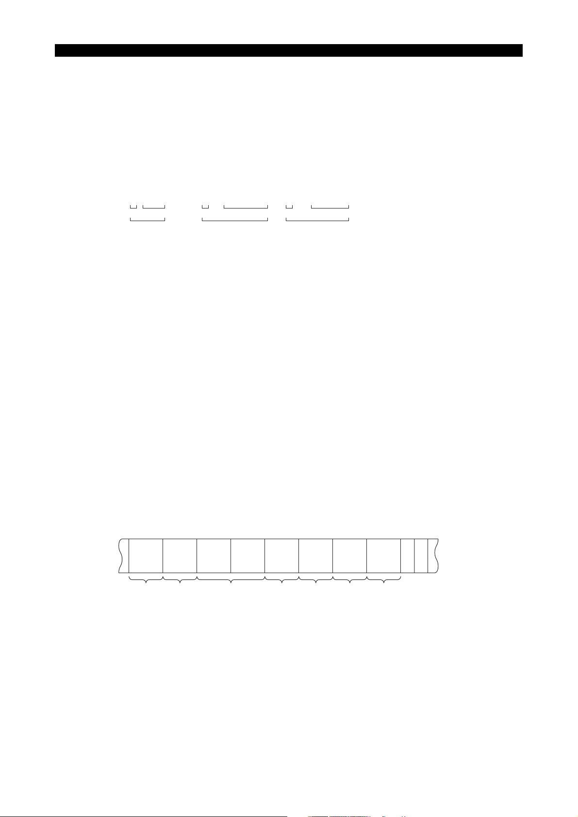
4. Program Format
4-1. Word Configuration
A word is defined as an address character followed by a group of numeric values, an expression, or
a variable name. If a word consists of an expression or a variable, the address character must be
followed by an equal sign “=”.
Examples:
5228-E P-4
SECTION 1 PROGRAM CONFIGURATIONS
X - 100
Address Numeric value
Word
Y = 100∗SIN[50]
Address
• An address character is one of the alphabetic characters A through Z and defines the meaning
of the entry specified following it. In addition, an extended address character, consisting of two
alphabetic characters, may also be used.
• Refer to SECTION 11, “Variable Function” for more information on variables.
• Hexadecimals may be used for numeric values.
Example: X#1000H (same as X4096)
4-2. Block Configuration
A group consisting of several words is called a block, and a block expresses a command. Blocks
are delimited by an end of block code.
• The end of block code differs depending on the selected code system, lSO or EIA:
ISO: LF
ElA: CR
• A block comprises several words.
Expression
Word
Z = VC1+VC2
Address
Variable
Word
ME33018R1000300040001
• A block may contain up to 158 characters.
A block consists of the following commands, for example.
N__ G__ X__ Y__ F__ S__ T__ M__
Feedrate
Sequence No.
Preparatory function
Coordinate values
Spindle speed
LC
FR
Tool No.
Miscellaneous function
ME33018R1000300050001

SECTION 1 PROGRAM CONFIGURATIONS
4-3. Program
A program consists of several blocks.
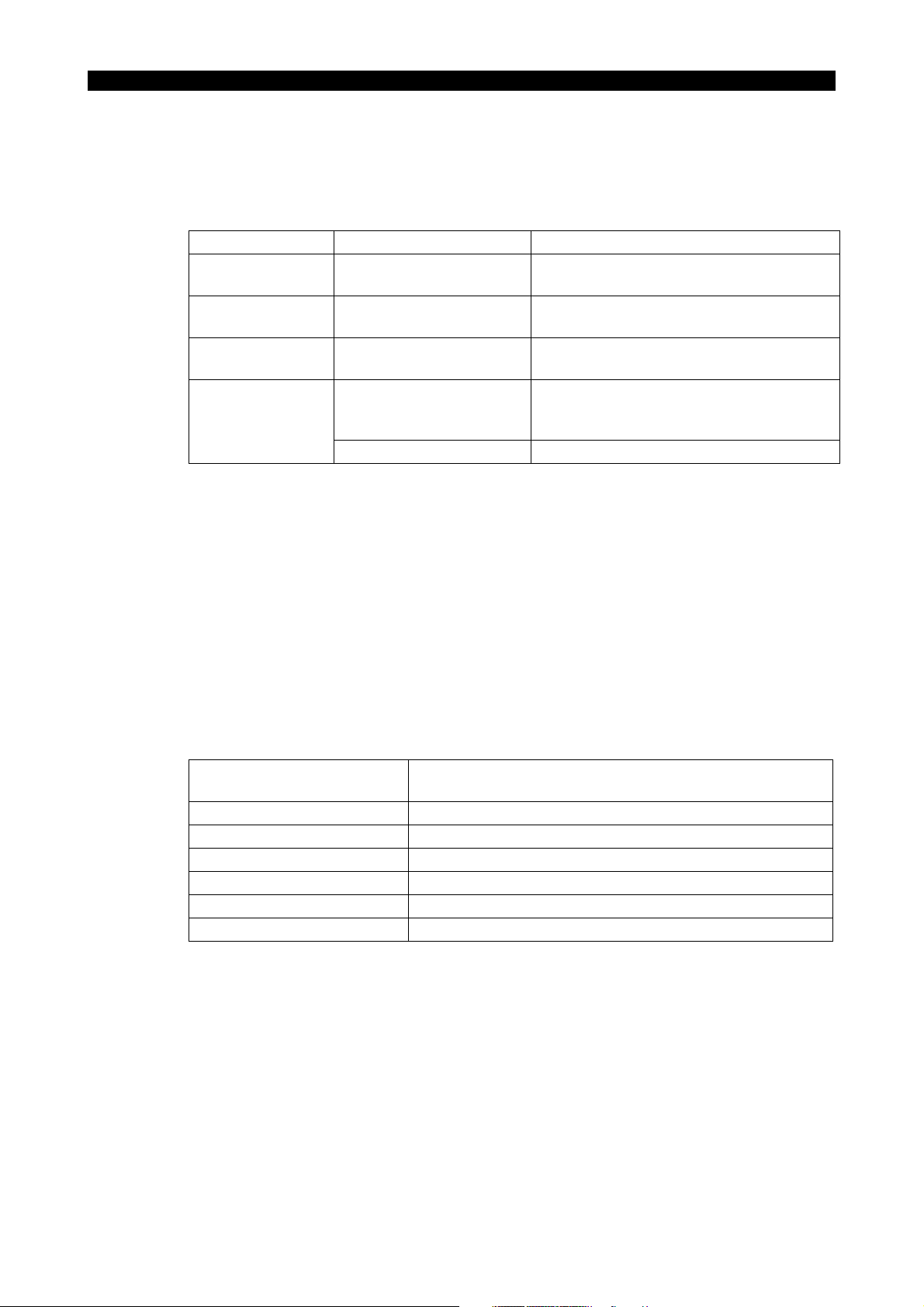
4-4. Programmable Range of Address Characters
The programmable ranges of numerical values of individual address characters are shown in the
following table.
5228-E P-5
Address Function
O Program name 0000 - 9999 Same as metric
N Sequence name 00000 - 99999 Same as metric
G Preparatory function 0 - 399 Same as metric Mnemonics available
X, Y, Z, U, V, W
I, J, K
R Radius of arc ±99999.999mm ±9999.9999inch
A, B, C
F
S Spindle speed 0 - 65535 Same as metric
T Tool number 1 - 9999 Same as metric
M
H
D
P
Q
R
Coordinate values
(linear axis)
Coordinate values of
center of arc
Coordinate values of
rotary axis
Feed per minute
Feed per revolution
Dwell time period 0.001 - 99999.999 sec Same as metric
Miscellaneous
function
Tool length offset
number
Cutter radius
compensation
number
Dwell time period
(during fixed cycle)
Second dwell time
period (during fixed
cycle)
Depth of cut (during
fixed cycle)
Repetition time
(schedule program)
Cut starting level
(during fixed cycle)
±99999.999mm ±9999.9999inch
±99999.999mm ±9999.9999inch
±360.0000deg Same as metric
0.001 - 500.000
1 to maximum tool data
1 to maximum tool data
0.001 - 99999.999 sec Same as metric
0.001 - 99999.999 sec Same as metric
±99999.999mm ±9999.9999inch
Programmable Range
Metric Inch
0.1 - 24000.0
mm/min
mm/rev
0 - 511 Same as metric
number
number
0 - 99999.999
mm
1 - 9999 Same as metric
0.01 - 2400.00
inch/min
0.0001 - 50.0000
inch/rev
Same as metric
Same as metric
0 - 9999.9999inch
Alphabetic characters
Alphabetic characters
specification
±9999.9999deg
Remarks
available
available
Multi-turn
*: An alarm occurs when any of the following addresses is specified more than once within a block:
X, Y, Z, U, V, W, A, B, C, F.

SECTION 1 PROGRAM CONFIGURATIONS
5. Mathematical Operation Functions
Mathematical operation functions are used to convey logical operations, arithmetic operations, and
trigonometric functions. A table of the operation symbols is shown below. Operation functions can
be used together with variables to control peripherals or to pass on the results of an operation.
Category Operation Operator Remarks
Exclusive OR EOR 0110 = 1010 EOR 1100 (See *3.)
Logical operation
Arithmetic
operation
Trigonometric
functions, etc.
Logical OR OR 1110 = 1010 OR 1100 (See *3.)
Logical AND AND 1000 = 1010 AND 1100 (See *3.)
Negation NOT 1010 = NOT 0101
Addition + 8 = 5 + 3
Subtraction - 2 = 5 - 3
Multiplication * 15 = 5 * 3
Division / (slash) 3 = 15/5
Sine SIN 0.5 = SIN [30] (See *4.)
Cosine COS 0.5 = COS [60] (See *4.)
Tangent TAN 1 = TAN [45] (See *4.)
Arctangent (1) ATAN 45 = ATAN [1] (value range: -90° to 90°)
Arctangent (2) ATAN2 30 = ATAN 2 [1,(Square root 3)] (See *1.)
Square root SQRT 4 = SQRT [16]
Absolute value ABS 3 = ABS [-3]
Decimal to
hexadecimal
conversion
Hexadecimal to
decimal
conversion
Integer
implementation
(rounding)
Integer
implementation
(truncation)
Integer
implementation
(raising)
Unit integer
implementation
(rounding)
Unit integer
implementation
(truncation)
Unit integer
implementation
(raising)
Remainder MOD 2 = MOD [17, 5]
BIN 25 = BIN [$25]
($ represents a hexadecimal number.)
BCD $25 = BCD [25]
ROUND 128 = ROUND [1.2763 x 102]
FIX 127 = FIX [1.2763 x 10²]
FUP 128 = FUP [1.2763 x 10²]
DROUND 13.265 = DROUND [13.26462] (See *2.)
DFlX 13.264 = DFlX [13.26462] (See *2.)
DFUP 13.265 = DFUP [13.26462] (See *2.)
5228-E P-6
SECTION 1 PROGRAM CONFIGURATIONS
Category Operation Operator Remarks
Brackets
*1. The value of ATAN2 [b, a] is an argument (range: -180° to 180°) of the point that is expressed
*2. In this example, the setting unit is mm.
*3. Blanks must be placed before and after the logical operation symbols (EOR, OR, AND, NOT).
*4. Numbers after function operation symbols (SIN, COS, TAN, etc.) must be enclosed in
Opening bracket [ Determines the order of calculation.
Closing bracket ]
by coordinate values (a, b).
brackets “[ ]”. ( “a”, “b”, and “c” are used to indicate the contents of the corresponding bits.)
(Expression in inner brackets is calculated first.)
Logical Operations
Exclusive OR (EOR) c = a EOR b
•
If the two corresponding values agree, EOR outputs 0.
If the two values do not agree, EOR outputs 1.
abc
000
011
101
110
5228-E P-7
• Logical OR (OR) c = a OR b
If both corresponding values are 0, OR outputs 0.
If not, OR outputs 1.
abc
000
011
101
111
• Logical AND (AND) c = a AND b
If both corresponding values are 1, AND outputs 1.
If not, AND outputs 0.
abc
000
010
100
111
• Negation (NOT) b = NOT a
NOT inverts the value (from 0 to 1, and 1 to 0).
ab
01
10

• Arc tangent (1) (ATAN)
θ = ATAN [b/a]
Arc tangent (2) (ATAN2)
θ = ATAN2 [b/a]
• Integer implementation (ROUND, FIX, FUP)
Converts a specified value into an integer (in units of microns) by rounding off, truncating, or
raising the number at the first place to the right of the decimal point.
6. Optional Block Skip
5228-E P-8
SECTION 1 PROGRAM CONFIGURATIONS
ME33018R1000300080001
[Function]
Blocks preceded by “/n” are ignored in automatic operation mode if the BLOCK SKIP switch on the
machine panel is set ON. If the switch is OFF, these blocks are executed normally. The optional
block skip function allows an operator to determine if a specific block should be executed or ignored
in automatic mode operation.
When the block skip function is called, the entire block will be ignored.
[Details]
• In the standard specification, one optional block skip can be specified; as an option, up to nine
are possible. These are distinguished in code as follows: “/1”, “/2”, “/3”. Note that “/” has the
same meaning as “/1” when this option is selected.
• A slash code “/” must be placed at the start of a block. If it is placed in the middle of a block, an
alarm is activated. A sequence name may precede a slash code “/”.
• A slash code “/” may not be contained in the program name block.
• Blocks which contain a slash code “/” are also subjected to the sequence search function,
regardless of the BLOCK SKIP switch position.
• Sequence stop is not executed at a block which contains a slash code “/” in single block mode
operation if the BLOCK SKIP switch is ON. The succeeding block is executed, and then the
operation stops.
• This function is also available in the schedule program.

SECTION 1 PROGRAM CONFIGURATIONS
7. Program Branch Function (Optional)
[Function]
The program branch function executes or ignores the program branch command specified in a part
program according to the ON/OFF setting of the PROGRAM BRANCH switch on the machine panel.
The function corresponds to maximum two program branch switches, PROGRAM BRANCH 1 and
PROGRAM BRANCH 2 (extended to maximum nine switches by additional option). If the switch is
ON, the program branches when the following command is read.
• IF VPBR1 N*** The program branches to N*** block if the PROGRAM BRANCH 1 switch is
ON.
• IF VPBR2 N*** The program branches to N*** block if the PROGRAM BRANCH 2 switch is
ON.
Example:
5228-E P-9
IF VPBR1 N100
G00 X100 Z100
G00 Y100N100
IF VPBR1 N200
G00 X200 Z200
G00 Y200
N200
M02
Branching to N100 if PROGRAM BRANCH 1 switch is ON.
Branching to N200 if PROGRAM BRANCH 2 switch is ON.
[Details]
• In operation method B (large-volume program operation mode), use a sequence label name to
specify the branch destination.
• The program branch function has the same restrictions as the branch function of User Task 1.
• A program branch command (IF VPBR1 N*** or IF VPBR2 N***) must be specified in a block
without other commands.
8. Comment Function (Control OUT/IN)
A program may be made easier to understand by using comments in parentheses.
ME33018R1000300100001
• A comment must be parenthesized to distinguish it from general operation information. All
information placed in parentheses is regarded by the machine as comments.
• Comments are displayed in the normal character size.
Example:
N100 G00 X200 (FIRST STEP)
Comment
ME33018R1000300110001
9. Message Function (Optional)
[Function]
For conditional branching it may be necessary to display a message, depending on the processing
at the destination of the branching. The message function is used in such cases, and the message
is displayed in enlarged characters.
[Format]
MSG (message statement)
[Details]
• The display of a message statement on the screen is twice the size of normal characters.
• If the MSG code is not followed by a message statement, the comment statement given last up
to the present block will be displayed.
• Up to 128 characters may be used in a message statement.
• The message function is possible only during machine operation mode.
• The following code can be used in the program to return the screen to he previous status after
the message has been displayed: NMSG
5228-E P-10
SECTION 1 PROGRAM CONFIGURATIONS
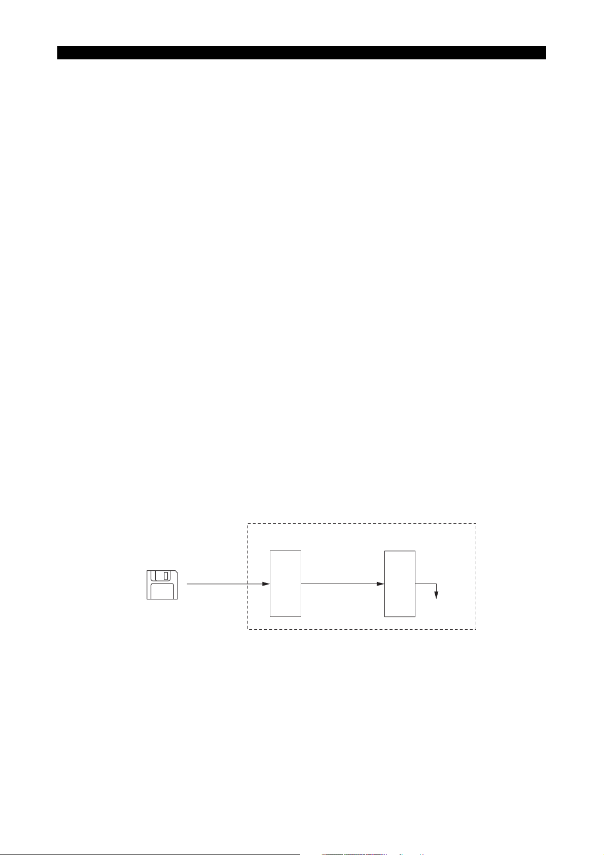
10. Operation Methods and Program Storage Memory Capacity
(1) Operation Capacity
The NC has a memory to store machining programs. The memory capacity is selected
depending on the size of the user program. On execution of a program, the program is
transferred from the memory to the operation buffer (RAM).
If the program size is larger than the operation buffer capacity, (for example, if the program size
is larger than 320 m (1050 ft.) although the operation buffer capacity is 320 m (1050 ft.)), the
program cannot be transferred from the memory to the operation buffer in batch (at one time).
Depending on the size of a program in comparison to the operation buffer capacity, two types of
operation methods are available (operation method A and operation method B), and restrictions
apply in programming according to the operation method used.
Machining program Memory
Program selection
Operation buffer
(RAM)
Operation
ME33018R1000300130001
5228-E P-11
SECTION 1 PROGRAM CONFIGURATIONS
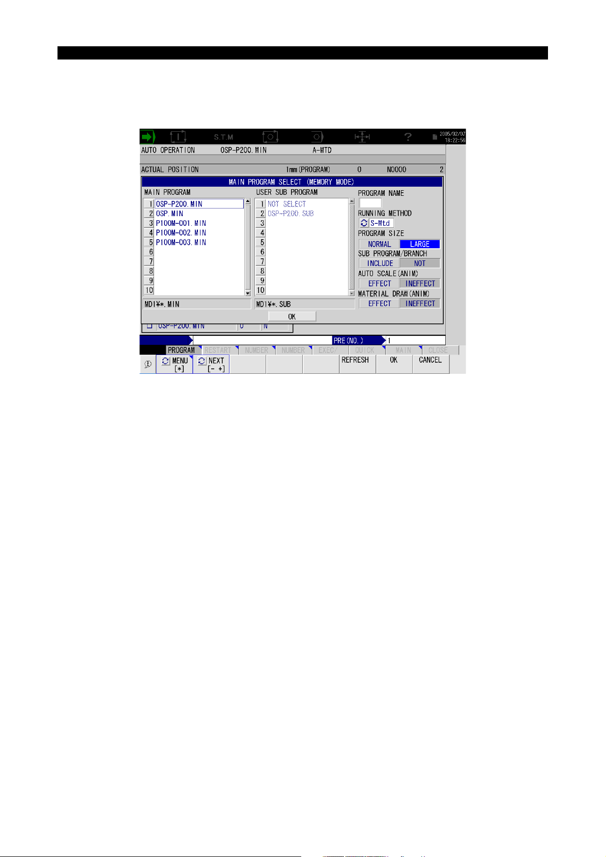
(2) Operation Methods
Select the operation method using the pop-up window MAIN PROGRAM SELECT (MEMORY
MODE) that appears when calling a program to be run. The operation method can be also
selected by the setting at the NC optional parameter (word) No. 11.
ME33018R1000300130002
• When A-Mtd is selected
Program running method A becomes effective.
The program to be executed is transferred to the operation buffer in batch.
This method is used when the program is smaller than the operation buffer capacity.
• When B-Mtd is selected
Program running method B becomes effective.
The program to be executed is called to the operation buffer in several segments.
This method is used when the program is larger than the operation buffer capacity.
Since schedule programs, subprograms, and library programs are generally called to the
operation buffer in batch, these programs must be created with restriction placed on their
capacities.
• When S-Mtd is selected
Program running method S becomes effective.
This method is used to execute a large program which does not use branch or subprogram
call functions.

5228-E P-12
SECTION 1 PROGRAM CONFIGURATIONS
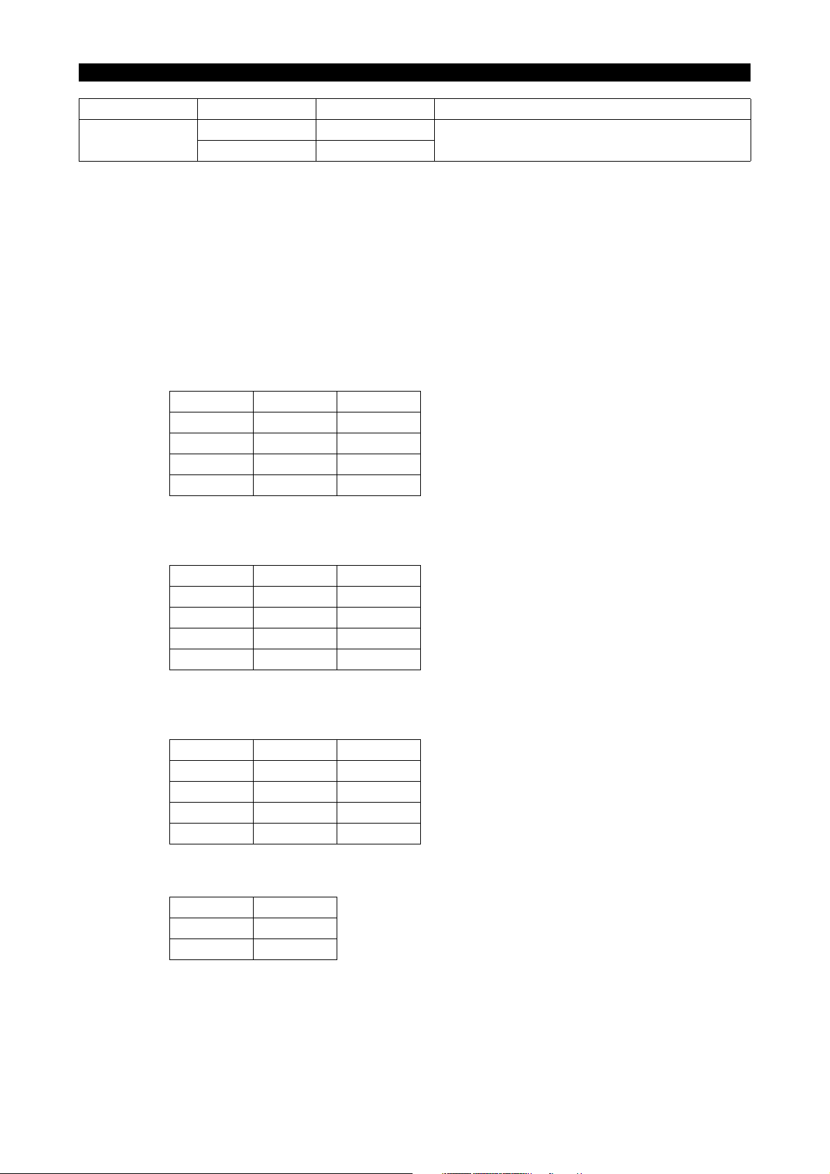
• When selecting an operation method, also select the program size and whether the
program has a sub program branch or not (only in the case of operation A and B). The
table below shows the relation between the operation method and the program size.
Item
Program running method Method A Method B Method S
Main program
Sub program
Program size
limit
Sub program function Usable Usable Unusable (alarm)
Branch function Usable Usable Unusable (alarm)
Destination of
a jump
specified in
branch
command
Main program sequence label
limit
Program selection time *1 *1 Completed immediately
Library
program
Schedule
program
Main program
Sub program
Library
program
Schedule
program
Program of normal
size
Total program size is
2MB.
Sequence label or
sequence number
Unlimited Unlimited Unlimited
Large program
2GB
Total program size is
about 1.8 MB.
Sequence label or
sequence number
-
Total program size is
about 1.8 MB.
-
*1. Time varies with the selected program size.
(3) Programming Restrictions for the Operation Method
For details of restrictions that must be taken into consideration when writing a program, refer to
SECTION 12, “PSELECT BLOCK”.
(4) Others
• The maximum capacity for running the main program is about 2 GB when the operation
method B is selected.
• The library program capacity is equivalent to the designated library program buffer size.
This means that the library program buffer size is always contained in the operation
capacity even if a library program is not registered.
• The number of subprograms and library programs stored in memory is independent of the
operation buffer size. They are always 126 and 65, respectively.

5228-E P-13
SECTION 2 COORDINATE SYSTEMS AND COORDINATE COMMANDS
SECTION 2 COORDINATE SYSTEMS AND COORDI-
NATE COMMANDS
1. Coordinate System
1-1. Coordinate Systems and Values
In order to move a cutting tool to a target position, a coordinate system must be established to
specify the target position using coordinate values in the coordinate system.
The OSP-P200M uses three types of coordinate system (machine coordinate system, work
coordinate system, and local coordinate system). These coordinate systems are briefly explained
below.
• Machine coordinate system
The machine coordinate system is set by the machine tool manufactures. Although the setting
may be changed by the user, machine dependent setting values such as pitch error
compensation data and travel limit values must be changed accordingly.
• Work coordinate system
A work coordinate system is set by the user.
• Local coordinate system
A local coordinate system set temporarily by the commands in a program.
The user can select the coordinate system to be used as needed from the coordinate systems
indicated above.
The coordinate value is represented by components of the axes which make up the coordinate
system. Usually, a maximum of six axis components is used (the number differs depending on
the NC unit specifications.)
Example:
X__Y__Z__W__A__C__
The number of programmable axes, that is, the number of axis components used to define a
coordinate value varies depending on the machine specifications. This manual, therefore, uses
the following designation to indicate a coordinate value.
IP__
1-2. Machine Zero and Machine Coordinate System
The reference point specific to the individual machine is referred to as the machine zero and the
coordinate system having the machine zero as the origin is referred to as the machine coordinate
system.
The machine zero is set for each individual machine using system parameters.
Since the travel end limits and the home positions are set in the machine coordinate system, the
user should not change the location of the machine zero at his/her own discretion.
A cutting tool may not always be moved to the machine zero.
ME33018R1000400010001
SECTION 2 COORDINATE SYSTEMS AND COORDINATE COMMANDS
1-3. Work Coordinate System
The coordinate system used to machine workpieces is referred to as the work coordinate system.
• Work coordinate systems are established and stored with work coordinate system numbers in
the memory before starting operation. The desired work coordinate system may be called at
the start of machining.
• Work coordinate systems are set by specifying the distance from the machine zero to the origin
of a work coordinate system as an offset value (work zero offset).
• For details, see SECTION 4, “Selection of Work Coordinate System” and SECTION 4, “Change
of Work Coordinate System”.
1-4. Local Coordinate System
Programming the entire operation of a workpiece using only a work coordinate system may
sometimes be difficult on some portions of the workpiece. In such cases, programming is facilitated
by setting a new coordinate system appropriate for a specific workpiece portion.
The new coordinate system is referred to as a local coordinate system.
5228-E P-14
• The desired local coordinate system can be established by specifying the origin in reference to
the origin of the presently selected work coordinate system and the angle of rotation on the
specified plane about the origin of the local coordinate system to be set with G11. Once a local
coordinate system has been established, all coordinate values are executed in the newly set
local coordinate system.
To change the local coordinate system to another one, the position of the origin of the new local
coordinate system and the angle of rotation about the origin should be specified with G11.
As explained above, a local coordinate system can be established only by specifying the
coordinate values of the origin and the angle of rotation in a program.
• To designate coordinate values in the work coordinate system, cancel the local coordinate
system by specifying G10.
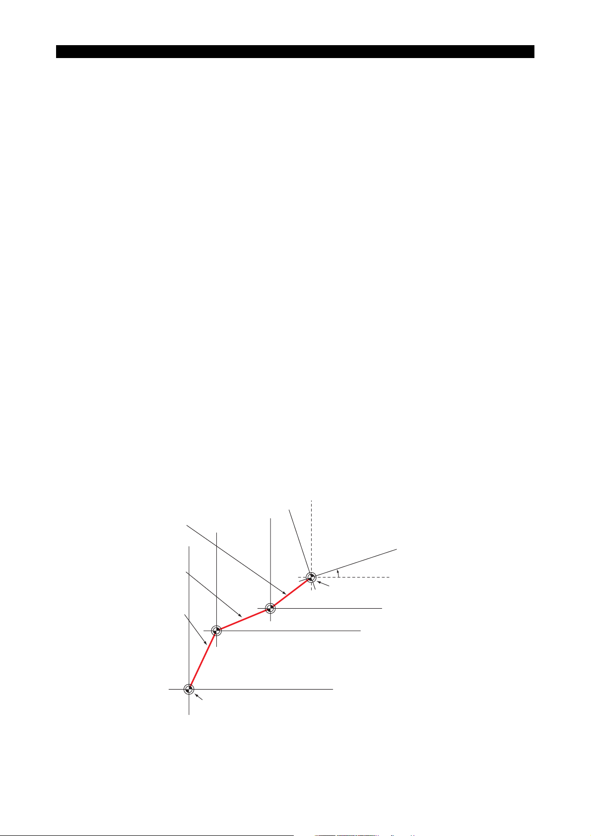
• For details, refer to SECTION 4, “Parallel Shift and Rotation of Coordinates System”.
Coordinate system parallel shift amount
(Specified in a program)
Work zero offset amount
(Set by zero point data)
Machine zero offset amount
(Set by system parameter)
Rotating angle of local coordinate system
Local coordinate system zero point
Work coordinate system zero point
Machine zero
Zero point for position encoder
ME33018R1000400040001
SECTION 2 COORDINATE SYSTEMS AND COORDINATE COMMANDS
2. Coordinate Commands
2-1. Numerically Controlled Axes
• The following table lists the addresses to be specified to control the axes.
Address Contents
Basic axis X, Y, Z
Parallel axis U, V, W
Rotary axis A, B, C
Circular
interpolation
parameters
• An axis movement command consists of an axis address, a sign indicating the direction of the
axis movement, and a numeric value which describes the axis movement. Refer to “Absolute
and Incremental Commands” for the designation of numeric values.
l, J, K
R Addresses specifying the radius of an arc
5228-E P-15
Addresses corresponding to the three axes
orthogonal to one another
Addresses of three orthogonal axes parallel
to the basic axes
Addresses of rotary axis in a plane right
angle to the basic axis
Addresses specifying distances, parallel to
an individual axis, from a start point to the
center of an arc
• In this manual, to simplify the explanation for axis designation, “Xp”, “Yp”, and “Zp” are used
instead of the actual axis addresses. They represent the axis as follows:
Xp X-axis and the axis parallel to X-axis (U-axis)
Yp Y-axis and the axis parallel to Y-axis (V-axis)
Zp Z-axis and the axis parallel to Z-axis (W-axis)
• The maximum number of controllable axes is six. This capability varies depending on the NC
model.
• The following table shows the number of simultaneously controllable axes in each of the axis
movement modes.
Number of Simultaneously Controllable Axes
(“n” represents the number of controllable axes.)
Positioning n
Linear interpolation n
Circular interpolation 2
Helical cutting 3
Manual operation 1
Pulse handle operation 1
In pulse handle operation, the optional 3-axis control function is available.
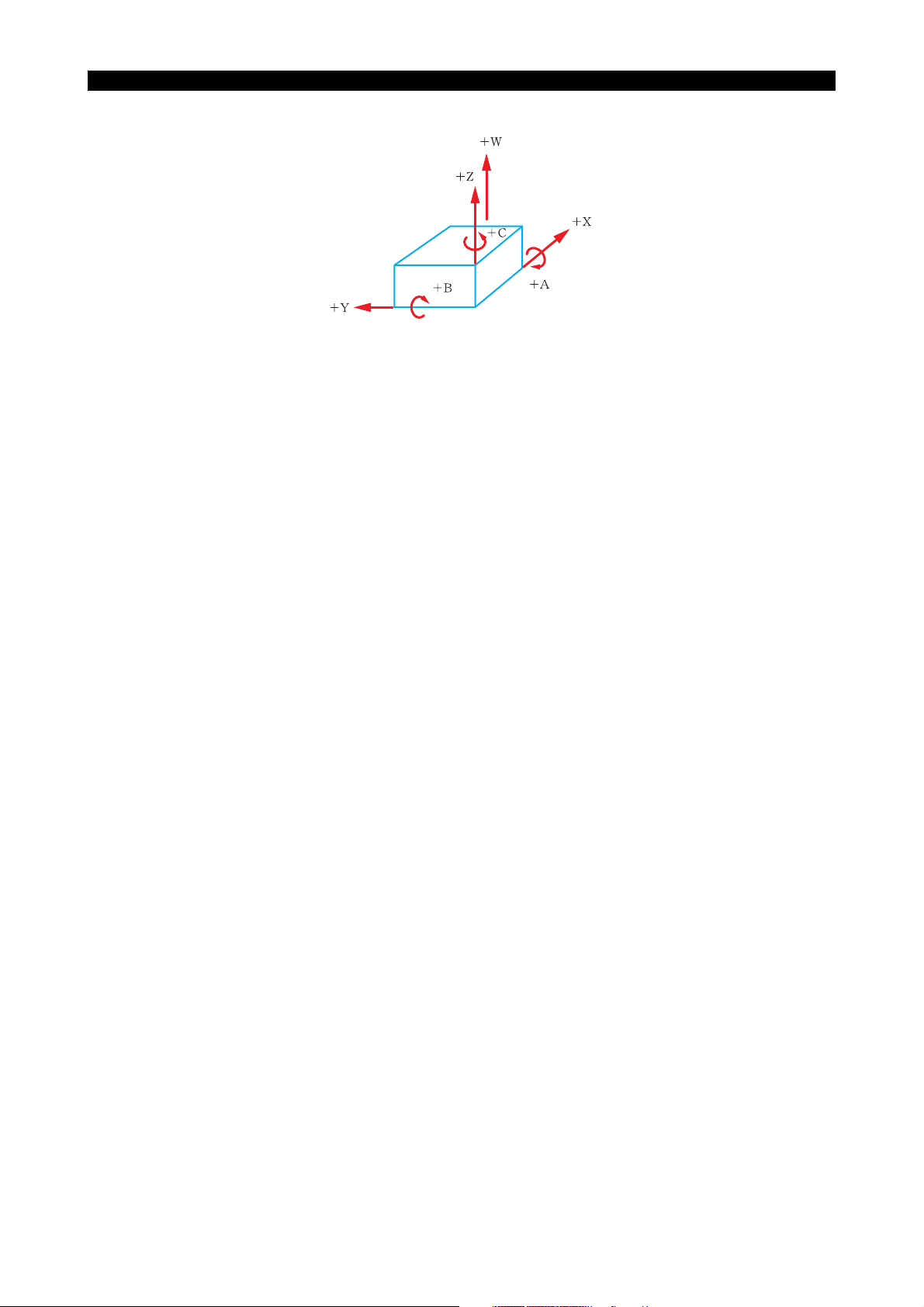
• The positive directions of the linear and rotary axes are defined as follows:
The definition of the coordinate axes and directions conforms to ISO R841.
ISO: International Organization of Standardization
2-2. Unit Systems
The unit systems that can be used in a program are described below. Note that the unit system
selected for programming and the unit system used for setting data such as zero point, tool data,
and parameters are independent of each other. The unit systems to be used for inputting the data
are set at NC optional parameter (INPUT UNIT SYSTEM).
5228-E P-16
SECTION 2 COORDINATE SYSTEMS AND COORDINATE COMMANDS
ME33018R1000400050001
2-2-1. Minimum Input Unit
The minimum input unit is the smallest unit of a value that may be entered in a program. For a linear
axis, the minimum input unit is 0.001 mm or 0.0001 inch.
For the NC with metric / inch switchable specification, the unit system can be selected by the setting
at LENGTH UNIT SYSTEM of NC optional parameter (INPUT UNIT SYSTEM).
For a rotary axis, the minimum input unit is 0.001 degree or 0.0001 degree. Either 0.001 degree or
0.0001 degree can be selected by the setting at ANGLE of NC optional parameter (INPUT UNIT
SYSTEM).
2-2-2. Basic Input Unit
The input unit may be changed to the “basic” unit by the setting at LENGTH of NC optional
parameter (INPUT UNIT SYSTEM). The fundamental units are then 1 mm, 1 inch, 1 degree, and 1
second.
SECTION 2 COORDINATE SYSTEMS AND COORDINATE COMMANDS
2-2-3. Numeric Values (inch / metric switchable as optional function)
As the unit for specifying program values, “mm”, “deg.”, “sec”, etc. are used. For these units, a
decimal point may be used.
• Cautions on using a decimal point value
a. A decimal point value must not be used for addresses O, N, G, and M.
b. If a decimal point is not entered in a numeric value, the decimal point is assumed to exist at
the end of the specified numeric value.
c. If a value is set below the specified minimum input unit, the data is processed in the
following manner.
• For addresses S, T, H, D, Q, etc. that require integer type data, the value below the
minimum input unit is truncated.
• For addresses that use real data, the value below the minimum input unit is rounded.
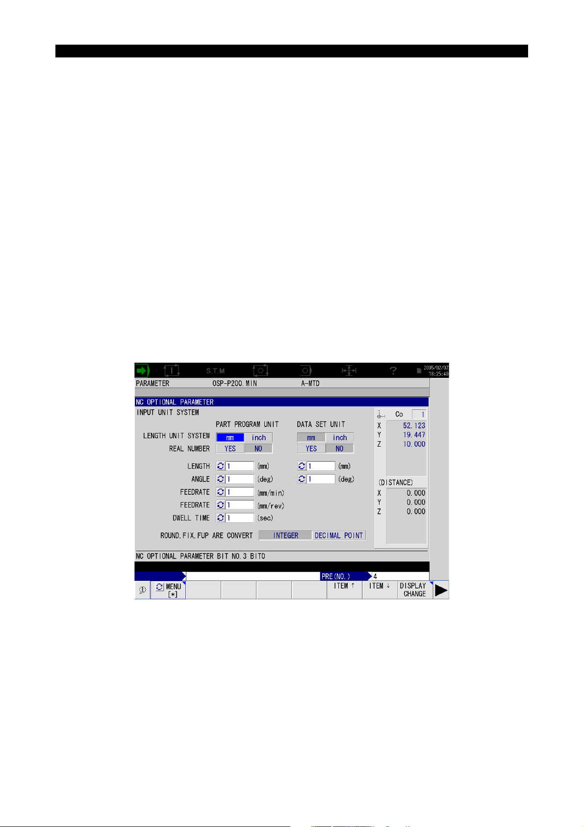
• The input unit of dimension commands is determined by the setting at NC optional parameter
(INPUT UNIT SYSTEM) or NC optional parameter (bit) No. 3, bit 0 to bit 7 and No. 4, bit 0. How
these bits set the input unit is shown below.
5228-E P-17
• NC optional parameter (INPUT UNIT SYSTEM) screen
ME33018R1000400090001
SECTION 2 COORDINATE SYSTEMS AND COORDINATE COMMANDS
• NC optional parameter (bit) No. 3, bit 0 to bit 7 and No. 4, bit 0
5228-E P-18
Parameter
No.
3
40
Bit
No.
Sets the unit system of length, “inch” or “mm”.
0
(*2)
1 Sets the unit of 1 mm, 1 inch, 1 deg., and 1 sec.
2 Sets unit of length, “0.01 mm” or “0.001 mm”. 0.01 mm 0.001 mm
Sets the unit of feedrate, 0.1 mm/min, 0.01
3
inch/min, or 1 mm/min, 0.1 inch/min
Sets the unit of feedrate, 0.001 mm/rev, 0.0001
4
inch/rev, or 0.01 mm/rev, 0.001 inch/rev
5 Sets the unit of time, “0.01 sec” or “0.1 sec”. 0.01 sec 0.1 sec
Sets the unit place at “1 mm”, “1 inch”, “1 deg”,
6
and “1 sec” when decimal point input is
selected.
7 Sets the unit time, “0.001 sec” or “0.1 sec”.(*1) 0.001 sec 0.1 sec
Sets the unit of angle, “0.001 deg” or “0.0001
deg”.
Contents
With
Check Mark
inch mm
Unit of 1 mm,
1 inch, 1 deg.,
and 1 sec is
selected.
0.1 mm/min
0.01 inch/min
0.001 mm/rev
0.0001 inch/rev
Unit place is set
at “1 mm”,
“1 inch”,
“1 deg”, and
“1 sec”.
0.0001 deg 0.001 deg
Without
Check Mark
Conforms to the
setting for bit 2
to bit 5 and bit 7
of No. 3 and bit
0 of No. 4.
1 mm/min
0.1 inch/min
0.01 mm/rev
0.001 inch/rev
Conforms to the
setting for bit 1
to bit 5, and bit
7.
*1: The unit of time is always “0.01 sec” if “1” is set for bit 5.
*2: The setting for bit 0 is valid only when the inch/mm switchable specification is selected.

SECTION 2 COORDINATE SYSTEMS AND COORDINATE COMMANDS
• Examples of parameter setting are given below.
(●: With check mark, O: Without check mark)
• mm system
• inch system
5228-E P-19
ME33018R1000400090002
ME33018R1000400090003
An asterisk (*) in the table indicates setting of “0” or “1” is allowed.
• µm / mm unit system
The unit system that handles the data in units of mm (inch) for real data and in units of microns
(1/10000 inch) is called the “µm / mm unit system”. For this unit system, the unit is determined
depending on whether or not a decimal point is used in the data when YES is selected at REAL
NUMBER of NC optional parameter (INPUT UNIT SYSTEM). If a decimal point is used, the unit
of “mm (inch)” is set and if a decimal point is not used, the unit of “microns (1/10000 inch)” is
set.
Example 1:
X100.
X100
If an expression or a variable is used for the command of this unit system, the values are
always treated as real data.
Example 2: Local variables
PX 100=
100mm
100µm
PX=X
100mm
PX 100.=
ME33018R1000400090004
PX=X
100mm
ME33018R1000400090005
(The value is not “100 µm”.)

5228-E P-20
SECTION 2 COORDINATE SYSTEMS AND COORDINATE COMMANDS
The following is a comparison how a numeric value is interpreted according to whether or not a
decimal point is used when “µm / mm unit system” is selected.
Command Element Value
X 100 100 µm–
X= 100 100 µm–
X 100. 100 mm Decimal point
X= 100. 100 mm Decimal point
X 100+100 200 mm Expression
X= 100.+100 200 mm Expression
X= 100+100. 200 mm Expression
X 100+100*2 300 mm Expression
X= 100+100*2 300 mm Expression
X= 100+100*2.5 350 mm Expression
PK= 100
X= 100+PK
PK= 100.
X= 200-PK
X= 200-100 100 mm Expression
X -100 -100 µm–
X -100. -100 mm Decimal point
X +100 100 µm–
X +100. 100 mm Decimal point
X= ROUND[100] 100 mm (*1) Expression
X= FIX[100.] 100 mm (*1) Expression
X= FUP[-100] -100 mm (*1) Expression
X= ROUND[100.] 100 µm (*2) –
X= FIX[100.] 100 µm (*2) –
X= FUP[-100.] -100 µm (*2) –
200 mm Variable
100 mm Variable
“mm unit system”
element
LA1=4 F=FIX[LA1] 4 mm/min
Variable
(*1) Decimal point is selected for designation of ROUND/FIX/FUP real number command.
(*2) Integer is selected for designation of ROUND/FIX/FUP real number command.
SECTION 2 COORDINATE SYSTEMS AND COORDINATE COMMANDS
2-3. Travel Limit Commands (G22, G23) (Optional)
Since the NC is equipped with absolute position encoders, it is possible to set the travel limit with the
software. That is, if the travel limit is set as an absolute value by the software, the limit switch
usually used to detect the travel limit may not be used. If the travel limit is set in this manner, it is
possible to change the travel limit position by changing the travel limit value in a program.
Note that two types of travel limit, one set by the manufacture (factory-set travel limit) and the other
set by the user (user-set travel limit), are provided.
(1) Factory-Set Travel Limit (Soft-Limit)
• The travel limit is set in accordance with the maximum travel distance from the machine
zero of each axis. The travel limits are set both in the positive (P) and negative (N)
directions using the system parameters.
• The area inside of the set values (from the N direction travel limit to the P direction travel
limit) is available for operation (operation permitted area). The outside area is called the
operation inhibited area and axis movements into this area are not allowed.
• The travel limit function always monitors the programmed tool path. If the tool path enters
the operation inhibited area, even if the end point lies in the operation permitted area, this
function disables the tool movement.
5228-E P-21
Operation inhibited area
End point
Start point
ME33018R1000400100001
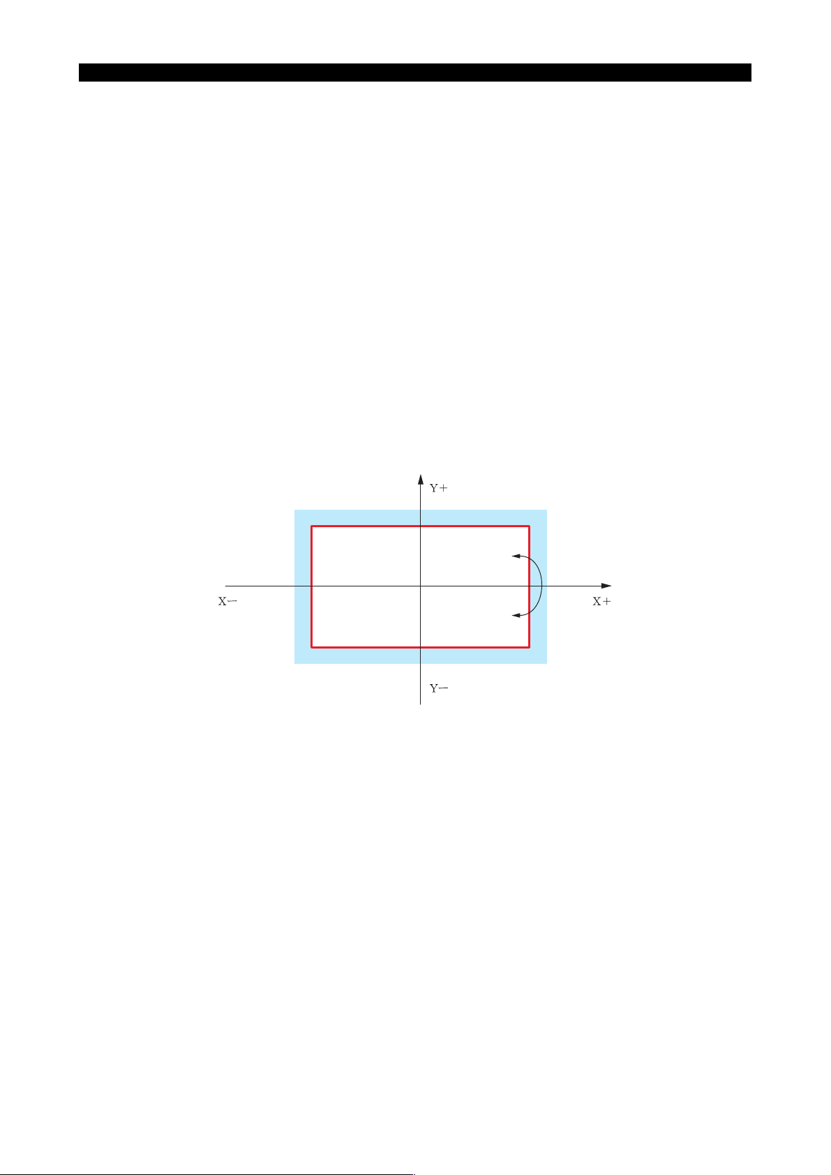
(2) User-Set Travel Limit (Programmable Limit) (Optional)
The travel limit may be set by the user either with user parameters or by programs using the
programmable travel limit function. Since both settings (user parameter and programmed
command) establish an identical area and since the data is stored in the same area, the data
entered last becomes the valid data, updating the previously set data. For example, when the
travel limits are set using a program after setting them with the user parameters, the travel limit
setting data is replaced with the data set for the user parameters. When setting the travel limits,
both positive (P) and negative (N) direction limit data must be set.
The area between the P and N travel limits is defined as the operation permitted area and that
outside the travel limits is defined as the operation inhibited area.

5228-E P-22
SECTION 2 COORDINATE SYSTEMS AND COORDINATE COMMANDS
• Setting the travel limits by a program
[Programming format]
G22 X__Y__Z__α__β__γ__I__J__K__P__Q__R__
X
...........
Y
...........
Z
...........
α
...........
β
...........
γ
...........
I
...........
J
...........
K
...........
P
...........
Q
...........
R
...........
The numeric values entered are processed as coordinate values in the work coordinate
system.
“α”, “β”, and “γ” above do not represent an address. In actual programming, use axis
addresses of the 4th to 6th axis (A, B, C, U, V, and W).
X Programmable limit in the P direction of X-axis
Y Programmable limit in the P direction of Y-axis
Z Programmable limit in the P direction of Z-axis
α Programmable limit in the P direction of 4th-axis
β Programmable limit in the P direction of 5th-axis
γ Programmable limit in the P direction of 6th-axis
I Programmable limit in the N direction of X-axis
J Programmable limit in the N direction of Y-axis
K Programmable limit in the N direction of Z-axis
P Programmable limit in the N direction of 4th-axis
Q Programmable limit in the N direction of 5th-axis
R Programmable limit in the N direction of 6th-axis
ME33018R1000400100002
[Details]
• An alarm occurs if the command indicated above is executed for the machine equipped with a
multi-turn type rotary axis.
• The data set using G22 is backed up and is therefore valid even after the power is turned off.
• If the setting data is outside the factory-set soft limits, an alarm will occur.
• Which of the travel limits - the limits set with the system parameters (soft-limit) or the limits set
with user parameters or by a program (programmable limits) - becomes valid as the operation
permitted area can be set by specifying an appropriate G code.
G22: Selects the travel limits set with user parameters or those newly set by G22 are as the
travel limits and checks the program according to the selected operation permitted area.
G23: Cancels the G22 mode and selects the travel limits set with the system parameters. The
program is checked according to the selected operation permitted area.
If G22 is specified independently, the programmable limit values set with user parameters
become valid.
• For setting the travel limits with user parameters, refer to User Parameter, SECTION 4
PARAMETER in III DATA OPERATION of OPERATION MANUAL.
• The programmed tool path is checked for entry into the operation inhibited area even if the end
point lies inside the operation permitted area.

SECTION 2 COORDINATE SYSTEMS AND COORDINATE COMMANDS
2-4. Home Position Command (G30)
[Function]
The term “home position” refers to a particular position that can be set for individual machines. The
home position command is used to move the axes to the preset home position.
The home position is used as the tool change position or the pallet change position.
[Programming format]
G30 P__
P: Home position number. Up to 32 home positions may be set.
Home positions are set with coordinate values in the machine coordinate system using system
parameters.
[Supplement]
The operating sequence of the axes to move to the home position and the position of the home
position are determined by the machine tool builder and differ according to machine. Before
operating the machine, you must thoroughly understand the axis operating sequence and the
position of the home position for each home position number.
For details on home positions, refer to SECTION 4 PARAMETER in III DATA OPERATION of
OPERATION MANUAL.
5228-E P-23
How the individual axes move to the home position is determined according to the setting for NC
optional parameter (bit) No. 46, bit 2, whether the path is generated along a straight line (linear
interpolation mode) or not.
[Supplement]
After the execution of a home position command, it is necessary to execute positioning for all axes
in the G90 mode (absolute command) before starting the next operation.

SECTION 2 COORDINATE SYSTEMS AND COORDINATE COMMANDS
2-5. Absolute and Incremental Commands (G90, G91)
For the designation of axis movement distance, two types of commands (absolute commands,
incremental commands) are available.
(1) Absolute Commands
G90 specifies the absolute dimensioning mode.
In this mode, the coordinate values in the selected work coordinate system are used to specify
the movement of axes.
(2) Incremental Commands
G91 specifies the incremental dimensioning mode.
In this mode, the axis movement distance from the current position to the target position is used
to specify the movement of axes.
[Details]
• It is not permissible to specify G90 and G91 in the same block.
• Either G90 or G91 is always valid.
• Which of G90 and G91 is made valid when the power is turned ON or when the NC is reset
is determined by the setting for a parameter (NC optional parameter (bit) No. 18, bit 4).
5228-E P-24
• When an incremental command needs to be designated right after the completion of a
fixed cycle, specify the movement of the cycle axis of the fixed cycle in the absolute mode
before specifying incremental commands.
G81 X_Y_Z_R_F_
X_Y_
•
•
•
•
X_Y_
G80
G00 Z_
G91 X_Y_Z_
•
•
•
•
ME33018R1000400120001
• After executing a command such as G15, G16, or G92 that changes a coordinate system,
it is necessary to execute positioning in the G90 mode for all axes. (After changing the
coordinate system, a coordinate system must be established using absolute commands.)

SECTION 2 COORDINATE SYSTEMS AND COORDINATE COMMANDS
2-6. Coordinate Recalculation Command (G97)
[Function]
After changing the home position (G30) or the coordinate system (G15, G16, G92, etc.), it is usually
necessary to issue G90 (absolute command) to position each axis (to define the coordinates). The
coordinate recalculation command eliminates such need.
[Programming format]
G97
[Supplement]
1) G97 is effective only in one block.
2) G97 cannot be specified with an axis movement command in the same block. If attempted, an
alarm occurs.
5228-E P-25

SECTION 3 FEED FUNCTIONS
1. Rapid Feed
In the rapid feed mode, each of the axes moves at the specified rapid feedrate independently of
other axes that are moved at the same time. Note that rapid feedrate differs depending on the
machine specification. Consequently, the individual axes arrive at the target point at different times.
Override is possible.
2. Cutting Feed
2-1. Feed per Minute (G94)
[Function]
This function sets the feedrate per minute of a cutting tool with a numeric value following address
“F”.
[Programming format]
G94
Setting unit:
Selection is possible from among 1 mm/min, 0.1 mm/min, 1 inch/min, 0.1 inch/min and 0.01 inch/min
by setting NC optional parameter (INPUT UNIT SYSTEM).
Setting range: 0.1 ~ 24000.0 mm/min, 0.01 ~ 2400.00 inch/min
[Details]
5228-E P-26
SECTION 3 FEED FUNCTIONS
• The allowable maximum feedrate that is called the “clamp feedrate” is set with NC optional
parameter (long word) No. 10. If an axis is going to move beyond this limit, its feedrate is
clamped at this clamp feedrate and the following alarm message is displayed at the alarm
display line on the screen.
4204 ALARM-D Feedrate command limit over (replacing)
• The programmed feedrate can be overridden. The clamp feedrate is applied to the actual
feedrate, or the overridden feedrate.
2-2. Feed per Revolution (G95)
[Function]
This function sets the feedrate per revolution of a cutting tool with a numeric value following address
“F”.
[Programming format]
G95
Setting unit:
Selection is possible from among l mm/rev, 0.01 mm/rev, 0.001 mm/rev, 1 inch/rev, 0.001 inch/rev or
0.0001 inch/rev by setting NC optional parameter (INPUT UNIT SYSTEM).
Setting range:0.001 ~ 500.000 mm/rev, 0.0001 ~ 50.000 inch
[Details]

• Since the clamp feedrate is set in units of “mm/min” it is converted into a value in “mm/rev” units
using the following formula:
fm = fr × N
where,
N = spindle speed (rpm)
fm = feedrate (mm/min)
fr = feedrate (mm/rev)
2-3. F1-digit Feed Function (Optional)
The F1-digit feed function has two types of control:
Switch-type control:
In a program, feedrate commands are written with F1 to F8 and the actual feedrate is set with the
corresponding setting switches (up to 8 sets) provided on the machine operation panel.
Parameter-type control:
The feedrate commands are written in a program in the same manner as with the switch-type
control. Actual feedrates are set for 9 sets of parameters F1 through F9.
For details of feedrate setting procedure for the parameter-type control, refer to the SECTION 11 F1digit Feed Command Function in Special Functions Manual.
• F1-digit feed designation is distinguished from F4-digit feed designation as follows.
5228-E P-27
SECTION 3 FEED FUNCTIONS
(1) F1-digit Feed
Switch-type control: An integer in the range of 1 to 8
Parameter-type control: An integer in the range of 1 to 9
(2) F4-digit Feed
If a real number (including a variable) is specified following address F (F1. for example), the
feedrate command is interpreted as an F4-digit command. Therefore, for the F1-digit feed
function, a variable cannot be used to specify 1 to 8 (for switch-type control) or 1 to 9 (for
parameter-type control).
Examples:
F1
F5.
LA1 = 8
F = LA1
The feedrate is determined by the setting of rotary switch F1.
Feedrate = 5 mm/min
Feedrate = 8 mm/min
ME33018R1000500040001
• The selected feedrate code (F1 to F8 in the case of switch-type control and F1 to F9 in the
case of parameter-type control) is not cleared even when the NC is reset. It is cleared if an
F4-digit command is specified or when power is turned OFF and then back ON.
• A feedrate override setting is invalid if a feedrate is specified by an F1-digit feedrate
command.
• If an F1-digit feedrate command is specified in the G95 mode (feed per revolution), an
alarm occurs.

2-4. F0 Command During Cutting Feed
F0 commands during the cutting feed are activated. When "F0", "F0.0", or "F0." is specified, the NC
operates considering the setting value of the optional parameter long word No. 62 as an F command
value. Specified F0 command is activated in the succeeding cutting blocks.
• If F0 commands are inactivated, the following alarm appears. "2244 ALARM-B Data word: 'F' 2"
Even if F0 commands are activated, an alarm appears as the current condition in the feed per
revolution mode.
• If [F0], [F0.], or [F0.0] is specified in a block of cutting feed command (including in the NURBS
mode, excluding synchronized tapping command), the value of the optional parameter long
word No.62 is adopted as the F value of the command. However, F0 commands are available
other than when specifying F commands directly.
• Not only X-, Y-, and Z-axes, commands are issued to the same block, regardless of whether W-
axis command is specified.
Since the upper-limit speed of the W axis is considerably low compared to the basic axes, if a
command is specified at the same time as the basic axes, the following alarm appears.
"ALARM-A CON speed over" (Same as usual.)
If this alarm occurs, set a lower value to the setting value of the optional parameter long word
No.62
5228-E P-28
SECTION 3 FEED FUNCTIONS
• The speed is clamped at the upper limit feedrate (in the Super NURBS control parameter). If a
desired speed cannot be achieved due to the upper limit feedrate, change the upper limit
feedrate.
• The speed is changed by the cutting feed override.
However, when the setting value of the optional parameter long word No.62 is 10 m/min, the
override is clamped at 10 m/min by the maximum feedrate value or upper limit feedrate even if
the override is set 100 % or more.
a. Optional parameter long word
No. Description Details
Feedrate value when
62
specifying F0 command
Set an F command value for the case when the F0 is specified. The setting is allowed up to
10 m/min.
If the setting value is "0", the initial value 10 m/min is automatically set on the initialization.
b. Optional parameter bit
NO. Bit Description
78 1 F0 command is not set as an
alarm.
Range 0 to 10000000
Initial value 10,000,000
Unit µm/min
Not set as alarm
Set as alarm
(Initial value)
This parameter is not effective when turning on the power.

SECTION 3 FEED FUNCTIONS
e
3. Exact Stop Check Function (G09, G61, G64)
[Function]
• During axis feed control, the calculated value always precedes the actual value when an axis is
moving to the target point. Therefore, if the calculated value is at the target point, the actual
value is behind the calculated value and is not at the target position. If the next block is
executed at the time the calculated value reaches the target point, the actual position follows
the calculated value, causing the tool path to stray from the programmed path at the join
between two blocks.
• The exact stop function successfully eliminates errors caused by the axis control indicated
above. With the exact stop function, operation for the next block does not start until the actual
value arrives at the target point even if the operation of the current block has completed, so that
the tool path exactly follows the programmed path.
The state where the current position has reached the target point is referred to as the “inposition” state. To establish the in-position state, the target point is defined with a band that is
set using a system parameter.
Calculated value
5228-E P-29
Actual valu
ME33018R1000500060001
• The exact stop check mode may be either one-shot (valid only for a programmed block) or
modal, as explained in the following.
Note that in the positioning mode (G00, G60), an exact stop check is always executed
regardless of whether or not an exact stop check G code is specified.
[Programming format]
• One-shot exact stop check command: G09 IP
Exact stop check is executed only in the specified block.
• Modal exact stop check command: G61 IP__
Exact stop check is executed for all blocks until a cutting mode (G64) is specified.
• Cutting mode (cancel G61): G64 IP__
At a join between blocks containing cutting commands, the commands in the next block are
executed immediately so that axis movements will not be decelerated at the join.
Even in the cutting mode, however, an exact stop check is executed in the positioning mode
(G00, G60) or in a block containing the one-shot exact stop command (G09).
An exact stop check is also executed at blocks where cutting feed does not continue.

SECTION 3 FEED FUNCTIONS
4. Automatic Acceleration and Deceleration
At the start and end of axis movements, axis feedrate is automatically accelerated and decelerated.
(1) Automatic Acceleration/Deceleration in Positioning Mode / Manual Feed Mode
Axis feed is accelerated and decelerated in a linear pattern as shown below.
Feedrate
5228-E P-30
Start point End point
Position
ME33018R1000500070001
(2) Automatic Acceleration/Deceleration in the Cutting Feed Mode (G01, G02, G03)
In the cutting feed mode, axis feed is automatically accelerated and decelerated in the
appropriate pattern as shown below.
Feedrate
Start point End point
Position
ME33018R1000500070002
(3) Processing Between Blocks
Type of New Block
Positioning Cutting Feed No Axis Movement
Type of Old Block
Positioning O O O
Cutting Feed O X O
No axis movement O O O
O: Program advances to the next block after executing the in-position check.
X: Program advances to the next block without executing the in-position check.
The term “in-position check” indicates the check if the actual axis position is within a
predetermined width from the specified coordinate value. The in-position width is set for a
system parameter.
(4) Exact Stop (G61, G09)
As indicated in the table above, since in-position check is not performed when cutting feed
blocks continue, the join between cutting feed blocks will be dulled or rounded. The exact stop
function prevents the join between such blocks from being dulled or rounded. For details, refer
to SECTION 3, “Exact Stop Check”.

5. Following Error Check
Following error is defined as the difference between the command value output from the NC and the
output of the position encoder. A DIFF over alarm occurs if a following error exceeds a certain value
during rapid feed or cutting feed of an axis.
Axis Move Distance
5228-E P-31
SECTION 3 FEED FUNCTIONS
Command position
Actual machine position
Calculated value with acceleration/deceleration processing
Following error (ODIFF)
ME33018R1000500080001

6. Positioning (G00)
[Function]
The axes move from the present position to the target position at rapid feedrate. During this
movement, axes are automatically accelerated and decelerated.
[Programming format]
G00 IP__
In the positioning operation executed in the G00 mode, in-position check is executed. The
commands in the next block are executed only after the in-position state is confirmed (in-position
width is set for a system parameter).
[Details]
• Whether positioning is executed in the linear pattern or a non-linear pattern is determined by the
setting for NC optional parameter (bit) No. 46, bit 0.
a. Linear interpolation pattern
The tool path is generated along a straight line from the actual position to the target
position. In this movement, the feedrates of the individual axes are determined within the
individual rapid feedrates so that positioning time can be minimized.
5228-E P-32
SECTION 3 FEED FUNCTIONS
Target position
Actual position
ME33018R1000500090001
b. Non-linear interpolation pattern
The individual axes move independently of each other at the individual rapid feedrates.
Therefore, the resultant tool path is not always a straight line.
Target position
Actual position
ME33018R1000500090002
• The rapid feedrate of the individual axes is set by the machine tool builder and cannot be
changed.
• The in-position range is set for each axis using system parameters.

7. Uni-directional Positioning (G60)
[Function]
• In the positioning called by G00, positional error is unavoidable if positioning is executed in
different directions due to backlash in the axis feed mechanism. If positioning is always
executed in the same direction, the influence of backlash is eliminated and therefore high
positioning accuracy can be obtained. The function to always execute positioning in the same
direction is called the unidirectional positioning function.
• If the positioning is going to be executed in the direction opposite to the direction set at
positioning direction of NC optional parameter (uni-directional positioning), the axis passes over
the target point once and then moves back to the target point. The amount by which the axis
passes beyond the target point (overrun amount) is set at either G60 overrun amount of NC
optional parameter (uni-directional positioning) or user parameter.
[Programming format]
G60 IP__
5228-E P-33
SECTION 3 FEED FUNCTIONS
[Details]
G00
G60
P direction
(positive)
P direction
(positive)
Target position
Target position
Overrun amount
N direction
(negative)
N direction
(negative)
ME33018R1000500100001
• When the linear interpolation mode positioning specification is provided, whether or not the
positioning is executed in the linear interpolation pattern is determined by the setting for NC
optional parameter (bit) No. 46, bit 1.
• If the direction of the specified positioning agrees with the positioning direction set at positioning
direction of NC optional parameter (uni-directional positioning), the axis does not pass over the
end point.
Start point
End point Start point
Overrun
ME33018R1000500100002

• G60 is a modal command.
• Uni-directional positioning is not valid for a cycle axis or shift movement in a fixed cycle.
• Uni-directional positioning is not valid on an axis for which no pass-over amount is set.
• Mirror image is not applied to the positioning direction.
8. Linear Interpolation (G01)
[Function]
In the G01 linear interpolation mode, axes move directly from the actual position to the specified
target point at the specified feedrate.
[Programming format]
G01 IP__F__
IP: Target point (end point)
F: Feedrate. The specified feedrate remains valid until updated by another value.
[Details]
• A feedrate value specified with address “F” is cleared to zero when the NC is reset. Note that
the F command value is saved when the NC is reset if a feedrate is specified in an F1-digit
command.
5228-E P-34
SECTION 3 FEED FUNCTIONS
• The feedrate for each axis is as indicated below. (For values X, Y, and Z, convert them into an
incremental value.)
G01 XxYyZzFf
Calculation of feedrates:
X-axis feedrate: FX =
Y-axis feedrate: FY =
Z-axis feedrate: FZ =
Where, L = x2+y2+z
For the rotary axis, the unit of feedrate is regarded as indicated below:
1 mm/min = 1 deg/min
1 inch/min = 1 deg/min
In linear interpolation including a rotary axis, the feedrates are determined according to the formulas
given above for the individual axes.
Example:
G91 G01 X10 C20 F30.0
<“mm” input>
X-axis feedrate FX =
C-axis feedrate FC =
2
102+20
102+20
x
f
L
y
f
L
z
f
L
10
x 30 13.41 mm/min
2
20
x 30 26.83 deg/min
2
ME33018R1000500110001
ME33018R1000500110002

<“inch” input>
5228-E P-35
SECTION 3 FEED FUNCTIONS
X-axis feedrate FX =
C-axis feedrate FC =
10
102+20
20
102+20
x 30 13.41 inch/min
2
x 30 26.83 deg/min
2
• When the F command (F=1) to the rotary axis in the inch system is issued, whether to interpret
"F1" as 1 deg/min or as 25.4 deg/min is set by NC optional parameter (bit) No. 15, bit 7.
9. Plane Selection (G17, G18, G19)
[Function]
Selecting a plane is necessary in order to perform the following functions:
• Circular interpolation (Helical cutting)
• Angle command (AG)
• Cutter radius compensation
• Coordinate rotation (Local coordinate system)
• Fixed cycle
ME33018R1000500110003
• Coordinate calculation
• Area machining
The planes that can be selected are indicated below:
G17 : Xp-Yp plane
G18 : Zp-Xp plane
G19 : Yp-Zp plane
[Programming format]
G17
G18
G19
Xp
Zp
Yp
Yp
Xp
Zp
Xp
Yp
Zp
...
...
...
X- or U-axis.
Y- or V-axis.
Z- or W-axis.
ME33018R1000500120001
ME33018R1000500120002

5228-E P-36
SECTION 3 FEED FUNCTIONS
[Details]
• Whether a basic axis (X, Y, Z) or a parallel axis (U, V, W) is selected is determined by the axis
addresses specified in the block containing G17, G18 or G19.
Examples:
G17
G17
G18
G18
G19
G19
X
U
Z
W
Y
Y
Y
_
Y
_
X
_
X
_
Z
_
W
_
plane
XY
_
plane
UY
_
plane
ZX
_
plane
WX
_
plane
YZ
_
plane
YW
_
ME33018R1000500120003
• In blocks where none of G17, G18, and G19 are specified, the selected plane remains
unchanged even if axis addresses are changed.
• In blocks where G17, G18, or G19 is specified, if an axis address is omitted, the basic axis (X,
Y, Z) is assumed to be omitted.
Examples:
G17
G17
G17
G18
G18
X
U
W
plane
XY
plane
XY
_
plane
UY
_
plane
ZX
plane
WX
_
ME33018R1000500120004
• If a command for an axis that does not exist in the plane selected in the G17, G18, or G19 block
is issued, the axis movement is performed regardless of selected plane.
• The plane to be selected when the power is turned ON or the NC is reset can be designated by
the setting at THE G CODE TO BE SET AUTOMATICALLY (PLANE) of the NC optional
parameter (AUTO SET AT NC RESET/POWER ON).
• An alarm occurs if both the basic axis and its parallel axis are specified in a plane selection
block.

10. Circular Interpolation (G02, G03)
[Function]
The circular interpolation function moves a tool from the actual position to the specified position
along an arc at the specified feedrate.
[Programming format]
5228-E P-37
SECTION 3 FEED FUNCTIONS
Arc on Xp-Yp plane : G17
Arc on Zp-Xp plane : G18
Arc on Yp-Zp plane : G19
G02
Xp__Yp__ F__
G03
G02
Zp__Xp__ F__
G03
G02
Yp__Zp__ F__
G03
R_
I_J_
R_
K_I_
R_
J_K_
Xp = X-axis or U-axis
Yp = Y-axis or V-axis
Zp = Z-axis or W-axis
• G codes used for the circular interpolation function are indicated below.
G17 : Plane selection : Sets the circular arc in the Xp-Yp plane.
G18 : Plane selection : Sets the circular arc in the Zp-Xp plane.
G19 : Plane selection : Sets the circular arc in the Yp-Zp plane.
G02 : Direction of rotation : Sets the clockwise direction.
G03 : Direction of rotation : Sets the counterclockwise direction.
Two axes among Xp, Yp, and Zp, G90 mode:
Sets the end point in the work coordinate system
Two axes among Xp, Yp, and Zp, G91 mode:
Sets the position in reference to the start point with signed values.
Two axes among I, J, and K:
Sets the distance from the start point to the center with signed values.
R: Sets the radius of an arc.
F: Sets the feedrate.
ME33018R1000500130001
[Details]
• Direction of rotation, clockwise or counterclockwise, is defined when viewing the plane from the
positive direction of the Zp-axis (Yp-axis, Xp-axis) on the Xp-Yp (Zp-Xp, Yp-Zp) plane, as shown
in the illustrations below.
ME33018R1000500130002

5228-E P-38
t
SECTION 3 FEED FUNCTIONS
• The end point is defined by either an absolute value or an incremental value according to G90
or G91.
The center point of an arc is determined by the I, J, and K values which correspond to Xp, Yp,
and Zp, respectively. Their coordinate values are always specified as incremental values,
regardless of G90 or G91.
End point
Center
Start point
End point
Center
Start point
End point
Center
Start poin
ME33018R1000500130003
A minus sign should be used for the I, J, and K values when necessary.
• The end point of an arc can be designated by specifying the coordinate value on one of the two
axes.
If only one axis is specified, the processing may be selected from the following two methods.
a. For axes with no command, the previous command value is used as the end point of the
arc. (For this processing, set the value for axis not programmed (circular single-axis) of NC
optional parameter (circular interpolation) as the current value.)
Vertical axis
Horizontal axis
Start point End point
X -70.711, Y -70.711
ex :
G02 X70.711 I70.711 J70.711
X -70.711, Y -70.711
G02 X10 I70.711 J70.711
When programming an arc as illustrated to the left,
the end point of the arc can be designated with
only the coordinate value of the horizontal axis,
since the coordinate value of the vertical axis is
the same at the start and end points. An alarm
occurs if the end point does not lie on an arc.
The left program defines a clockwise arc:
Radius: 100
Center: (0, 0)
Start point: (-70.711, -70.711)
End point: (70.711, -70.711)
The left program will cause an alarm, since the
end point (10, -70.711) is not on the arc.
ME33018R1000500130004
b. For the omitted axis, the coordinate value is calculated using the coordinate value of the
specified axis. For this processing, choose point on arc at command value for the axis not
programmed (single-axis) of NC optional parameter (circular interpolation).
When programming an arc as illustrated in the left,
the end point can be designated with only the
horizontal axis coordinate value. The vertical axis
coordinate value is calculated from the horizontal
axis coordinate value.
ME33018R1000500130005
G02
Start point
End point
G03

5228-E P-39
SECTION 3 FEED FUNCTIONS
• If more than one end point is possible, the one which is reached first in the designated arc
direction is selected.
Example:
X-70.711 Y-70.711 F200
G02 X10 I70.711 J70.711
The program to the left defines a clockwise arc:
Radius: 100
Center: (0, 0)
Start point: (-70.711, -70.711)
End point: (10,99.499)
ME33018R1000500130006
The operations explained above also apply when designation of a vertical axis is omitted.
• The center of an arc can be defined by specifying the radius (R) of the arc instead of specifying
I, J, and K. If an arc is specified by the radius, four arcs that pass the same start and end points
are defined. To define a specific arc from among these four arcs, an R value is used in the
manner indicated below.
• Clockwise arc (G02)
An arc whose central angle is smaller than or equal to 180 degrees: Radius R > 0
An arc whose central angle is greater than 180 degrees: Radius R < 0
• Counterclockwise arc (G03)
An arc whose central angle is smaller than or equal to 180 degrees: Radius R > 0
An arc whose central angle is greater than 180 degrees: Radius R < 0
End point
Start point
End point
Start point
ii) Counterclockwise arc i) Clockwise arc
ME33018R1000500130007
• The feedrate in circular interpolation is the feedrate component tangential to the arc.
[Supplement]
• If I, J, or K is omitted, it is regarded that “0” is specified.
• An arc with radius 0 (R = 0) cannot be specified.
• If the values for Xp, Yp, and Zp are omitted, an arc having the start and end points on the same
point is defined in the following manner:
a) If the center is specified by I, J, and/or K, a 360-degree arc
b) If the radius is specified by R, a 0-degree arc
• It is not possible to specify R, and I, J, and K at the same time.
• It is not possible to specify any axis parallel to the axes which make up the selected plane. For
example, designation of the W-axis is not allowed when the Z-X plane is selected.
• An alarm will occur if the difference in radius between the start point and the end point of an arc
is greater than or equal to the value set at arc check data (difference in radius between start
and end) of the NC optional parameter (circular interpolation).

11. Helical Cutting (G02, G03) (Optional)
[Function]
Helical cutting or helical interpolation may be executed by synchronizing circular interpolation with
linear interpolation of the axis which intersects at right angles the plane in which the arc is defined.
[Programming format]
5228-E P-40
SECTION 3 FEED FUNCTIONS
XpYp plane : G17
α : An axis not parallel to the axes comprising the arc plane
G02
Xp__Yp__ α__F__
G03
R_
I_J_
ME33018R1000500140001
[Details]
• Helical cutting may also be programmed on the Zp-Xp (G18) and Yp-Zp (G19) planes, using a
format similar to that above.
• To program helical cutting, simply add the command of the axis which intersects the arc plane
to the circular interpolation.
• Helical cutting is possible for an arc having a center angle of smaller than 360 degrees.
• The feedrate specified by an F command is valid for circular interpolation. Therefore, the
feedrate in the direction of the linear axis is calculated by the following formula:
Feedrate in the linear axis direction =
Motion distance of the linear axis
Arc length
x F
ME33018R1000500140002
• Tool length offset is valid for the axis at right angles to the arc plane.
• Cutter radius compensation is valid only for circular interpolation commands.

5228-E P-41
SECTION 4 PREPARATORY FUNCTIONS
SECTION 4 PREPARATORY FUNCTIONS
G codes consisting of address character G and a three-digit number (00 to 399) set the mode that specifies
how the commands are executed.
Instead of using address character G, some G codes are expressed by mnemonics. A mnemonic code
consists of up to eight alphabetic characters (A to Z).
• Valid range of G codes
One-shot G codes:
Valid only in the specified block. Such G codes are automatically canceled when a program advances to
the next block.
Modal G codes:
Once specified, such G codes remain valid until another G code in the same group is specified.
• Special G codes
Mnemonic codes used for subprogram call and those used as branch instructions are called special G
codes.
Special G codes must be specified at the beginning of a block and entry of such codes at a middle of a
block is not allowed. Note, however, that a slash “/” code (optional block skip code) or a sequence name
may be placed before a special G code.
• For the tables of G codes and mnemonic codes, refer to “G Code Table” and “Table of Mnemonic Codes”
in APPENDIX.
1. Dwell Command (G04)
[Function]
At the end of the specified block, the dwell function suspends the execution of a program for the
specified length of time before proceeding to the next block.
[Programming format]
The following two programming formats may be used to specify the dwell function.
• G04 F__
F: Sets the length of dwell time
The unit of dwell time can be selected from 1, 0.1, 0.01 and 0.001 seconds by the NC optional
parameter (INPUT UNIT SYSTEM).
The maximum programmable dwell time is 99999.999 seconds.
• G04 P__
P: Sets the length of dwell time
The unit of dwell time is selected in the same manner as when specified by F.

SECTION 4 PREPARATORY FUNCTIONS
2. Programmable Mirror Image (G62) (Optional)
[Function]
The mirror image function creates a geometry which is symmetric around a specific axis. In addition
to the mirror image switch on the machine panel, the programmable image function creates mirror
images using programmed commands.
The axis which is in the mirror image mode is identified on the screen display; a dash “-” is added
before the axis name on the ACTUAL POSITION screen.
[Programming format]
5228-E P-42
G62 IP
0
1
0 : Normal (Mirror image OFF)
1 : Mirror image
ME33018R1000600030001
[Details]
• The actual state of the mirror image function based on the specification of G62 and the
MIRROR IMAGE switch setting is displayed in the table below.
G62 Switch Setting Actual State
Normal Normal Normal
Normal Mirror image Mirror image
Mirror image Normal Mirror image
Mirror image Mirror image Normal
ME33018R1000600030002
• A block in which G62 is specified must not contain any other commands.
• The mirror image function is modal.
• The axes not specified in the G62 block are assumed to be in the normal mode.
• All axes are in the normal mode when the power supply is turned on.
• Whether all axes will be set in the normal mode or not when the NC is reset can be set at AT AN
NC RESET, CLEARS THE G62 MIRROR IMAGE FOR ALL AXES of NC optional parameter
(MIRROR IMAGE).
• The coordinate system (local or work) in which the mirror image function will be active can be
selected at local/work coordinate system select of NC optional parameter (MIRROR IMAGE).
Example:
G11 X40 Y10 P45
G01 X5
G62 X1
X30
Y5
Y5
Y30
Y5
S__F__
ME33018R1000600030003

5228-E P-43
SECTION 4 PREPARATORY FUNCTIONS
(1) If work is selected at local/work coordinate system select of NC optional parameter (MIRROR
IMAGE)
X - Y
: Work coordinate system
X' - Y'
: Local coordinate system
ME33018R1000600030004
(2) If local is selected at local/work coordinate system of NC optional parameter (MIRROR IMAGE)
ME33018R1000600030005

SECTION 4 PREPARATORY FUNCTIONS
3. Work Coordinate System Selection (G15, G16)
[Function]
20 sets of work coordinate systems are supplied as a standard feature and this can be expanded to
50, 100 or 200 sets optionally.
[Programming format]
Modal G code: G15 Hn (0 ≤ n ≤ 200)
Once a new work coordinate system “n” is set using the modal G code, the coordinate values
specified in the same and later blocks are interpreted as coordinate values in the selected work
coordinate system “n”.
One-shot G code: G16 Hn (0 ≤ n ≤ 200)
If a new work coordinate system “n” is set using the one-shot G code, only the coordinate values
specified in the same block are interpreted as coordinate values in the selected work coordinate
system “n”.
[Details]
• For G15 and G16, the work coordinate system number between 1 and 200 is specified by “n” (1
to 200). If “0” is specified for “n”, the machine coordinate system is selected.
• When the power supply is turned ON, and after the NC is reset, the work coordinate system
previously selected by G15 is automatically selected.
5228-E P-44
• G15 and G16 may not be specified in the following modes:
• Cutter radius compensation mode
• Three-dimensional offset mode
• Geometry enlargement/reduction mode
• Coordinate system parallel shift/rotation mode
[Supplement]
Axis feed commands specified immediately after G15 must be specified in the absolute mode.

SECTION 4 PREPARATORY FUNCTIONS
4. Work Coordinate System Change (G92)
[Function]
The work coordinate system change function changes the work coordinate system.
[Programming format]
G92 IP__
[Details]
• G92 automatically changes the work zero offset value of the presently selected work coordinate
system so that the coordinate value of the present tool position will be the coordinate value
specified as IP__.
• G92 changes only the work coordinate system that is selected at the time it is executed; it does
not affect any other work coordinate systems.
• The coordinate value P specified in this block is always treated as an absolute value regardless
of the specification of G90 (absolute mode) and G91 (incremental mode).
• For the axis not specified with the coordinate value P, the work zero offset value remains
unchanged.
• G92 may not be specified in the following modes:
5228-E P-45
• Cutter radius compensation mode
• Three-dimensional offset mode
• Geometry enlargement/reduction mode
• Coordinate system parallel shift/rotation mode
• Machine coordinate system selected mode
5. Unit System Check (G20, G21) (Optional)
[Function]
The unit system check function checks the unit system selected by the setting at LENGTH UNIT
SYSTEM of NC optional parameter (INPUT UNIT SYSTEM). If the selected system does not agree
with the unit system specified by G20 / G21, an alarm occurs.
[Programming format]
G20:Checking for the selection of the inch system
An alarm occurs if the metric system is selected by the setting for the parameter.
G21:Checking for the selection of the metric system
An alarm occurs if the inch system is selected by the setting for the parameter.

5228-E P-46
SECTION 4 PREPARATORY FUNCTIONS
6. Coordinate System Conversion Functions
6-1. Parallel Shift and Rotation of Coordinate Systems (G11, G10)
[Function]
The parallel shift / rotation function shifts or rotates a work coordinate system. The new coordinate
system defined by shifting or rotating a work coordinate system is called a local coordinate system.
It is possible to cancel a local coordinate system.
[Programming format]
Parallel shift / rotation of coordinate system: G11 IP__ P__
IP: Parallel shift amount to establish a local coordinate system
Specify the shift amount as an absolute value in reference to the origin of the work coordinate
system, regardless of the selected dimensioning mode, absolute mode (G90), incremental
mode (G91), or mirror image (G62).
P: Rotation amount to establish a local coordinate system
Specify the angle of rotation in units of 1 degree, 0.001 degree, or 0.0001 degree in
accordance with the selected unit system (LENGTH UNIT SYSTEM and ANGLE of NC
optional parameter (INPUT UNIT SYSTEM)).
If “P0” is specified or a P command is not specified, only work coordinate system shift takes
place, without rotation.
Rotation of a work coordinate system is executed in the plane (G17, G18, G19) that is active
when G11 is specified, and it does not affect the axes not included in this plane. The direction
of rotation is counterclockwise viewed from the positive direction of the axis not included in
the rotation plane.
Specify the angle of rotation as an absolute value, regardless of the selected dimensioning
mode (G90, G91).
• Cancellation of local coordinate system: G10
When G10 is specified, the parallel shift amount and angle of rotation are canceled.
[Details]
• Once G11 is executed, the NC enters the state in which a local coordinate system is defined. If
G11 is executed again in this state, it will change the previously defined local coordinate
system. At the second designation of G11, if the designation of an axis address is omitted, the
value designated in the first G11 is assumed to apply. The set values are cleared when the
power supply is turned OFF / ON, the NC is reset, or G10 (local coordinate system cancel) is
executed.
• A block which contains G10 or G11 must not contain any other G codes.
• G10 and G11 are modal. G10 is set when the power is turned ON or when the NC is reset.
• G11 must not be specified in the following modes:
• Geometry enlargement/reduction mode
• When the machine coordinate system (H00) is selected
• Copy function mode

5228-E P-47
SECTION 4 PREPARATORY FUNCTIONS
[Example program]
If a local coordinate system is used, the example workpiece shown below would be programmed as
indicated in the example program.
Machine coordinate system
Zero point of local coordinate system
Zero point of work coordinate system
Y0
G00
N1
N2
N3
N4
N5
N6
N7
N8
N9
N10
N11
N12
∗ : The zero offset values of work coordinate system 1 are : x= 25, y = 15
G90
G15
F100
X60
G01
Y40
X0
Y0
X20X0Y10
G11
G17
Y0
X0
X30
Y10
X0
Y0
...................................
G10
..........
P40
....................
....................
H01
Selecting work coordinate system 1
Setting a local coordinate system
Canceling a local coordinate system
ME33018R1000600070001

6-2. Copy Function (COPY, COPYE)
[Function]
The copy function is used to facilitate part machining by repeating the same pattern with parallel
shift and rotation.
First, specify parallel shift and rotation of a local coordinate system using COPY instead of G11,
then program the pattern to be repeated. Finally, specify the incremental value of parallel shift /
rotation.
[Programming format]
Parallel shift/rotation of local coordinate system: COPY IP__ P__ Q__
IP: Initial value of parallel shift component to establish a local coordinate system
Specify this as an absolute value in reference to the origin of the presently selected work
coordinate system.
P: Initial value of rotation component to establish a local coordinate system
Specify this value in units of 1 degree, 0.001 degree, or 0.0001 degree in accordance with
the selected unit system (“LENGTH UNIT SYSTEM” and “ANGLE” of NC optional parameter
(INPUT UNIT SYSTEM)).
If a P command is not specified in the G11 mode, the previous setting is valid.
Q: The number of times the pattern should be repeated.
Setting range: 1 to 9999
Default value: 1
5228-E P-48
SECTION 4 PREPARATORY FUNCTIONS
Repeated pattern program: COPYE IP__ P__
IP: Incremental value for parallel shift of a local coordinate system.
Default value: 0
P: Incremental value for rotation of a local coordinate system.
Default value: 0
[Details]
• Both G11 and COPY may be specified while a local coordinate system is established by the
execution of G11. Once COPY is specified, however, an alarm occurs if G11 or COPY is
specified again.
• If COPY is specified in the main program selected for operation method B (large-volume tape
operation), designation of IF and GOTO is not permissible in the program that defines the
pattern to be repeated.
The size of the program beginning with COPY and ending with COPYE must be within 10 m (33
ft) in tape length.

[Example program]
Zero point of local
coordinate system
G11
G01
COPY
G01
G03
G01
COPYE
X15
X30
Q4
X30
X0
X0
P - 30
Y25
M03
F100
...........................................
Y0
Y30I - 20J10
.........................................
Y30
P90
5228-E P-49
SECTION 4 PREPARATORY FUNCTIONS
Zero point of work coordinate system
Start point of arc
End point of arc
∗ : Circular interpolation commands must not be specified in the block immediately
after the COPY block and the one immediately before the COPYE block.
ME33018R1000600080001

5228-E P-50
g
SECTION 4 PREPARATORY FUNCTIONS
7. Workpiece Geometry Enlargement / Reduction Function (G51, G50) (Optional)
[Function]
The workpiece geometry enlargement / reduction function enlarges or reduces the geometry
defined by a program in reference to the point specified in a local coordinate system. If a local
coordinate system is not specified, a work coordinate system is used to specify the reference point
for enlargement / reduction.
[Programming format]
Enlargement / reduction of geometry: G51 IP __ P__
IP: The center of the enlargement / reduction of geometry.
Specify this point in a local coordinate system.
For axes not specified in this block, the coordinate value (in the local coordinate system) of
the point at which G51 is specified is assumed to apply.
P: Multiplication factor for enlargement or reduction.
Programmable range: 0.000001 to 99.999999
Default value: 1
Cancellation of enlar
P0
P1 - P4
P'1 - P'4
ement / reduction : G50
: Center of enlargement / reduction
: Programmed geometry
: Reduced geometry
ME33018R1000600090001
[Details]
• The enlargement/reduction function is made valid or invalid on individual axes according to the
setting for NC optional parameter (geometry enlargement/reduction). However, an alarm will
occur in the radius check if the parameter setting differs among the axes in the plane specified
for circular interpolation.
• The enlargement/reduction function does not affect the following:
a. Local coordinate system setting values (G11)
b. Cutter radius compensation values and three-dimensional offset values (G41, G42, G43)
c. Tool length offset values (G54 to G59)
d. Work coordinate system setting values (G92)

SECTION 4 PREPARATORY FUNCTIONS
e. The following Z-axis movements in a fixed cycle:
• In-feed and retraction amounts in deep hole drilling cycle (G73, G83)
• X, Y shift amounts in fine boring or back boring (G76, G87)
Example:
Cutter radius compensation and enlargement and reduction of workpiece geometry
5228-E P-51
ME33018R1000600090002
[Example program]
An example program for setting a local coordinate system and enlarging/reducing workpiece
geometry is shown below.
N1
G17
G11
X50
N2
G90
G51
X20
N3
G01
X40
N4
N5
N6
Y20
X0
Y0
Geometry after setting a local coordinate
system and reducing geometry
Y30
Y10
P45
Setting of local coordinate system
P0.5
Reduction of geometry
Positioning at P'1
Positioning at P'2
Positioning at P'3
Positioning at P'4
Local coordinate
system
Geometry after setting a local coordinate system
Reduction only
Geometry defined by a program
Work coordinate system
ME33018R1000600090003

5228-E P-52
SECTION 5 S, T, AND M FUNCTIONS
SECTION 5 S, T, AND M FUNCTIONS
This section describes the S, T, and M codes which specify necessary machine operations other than axis
movement commands.
S: Spindle speed
T: Tool number for tool change cycle
M: Turning solenoids and other similar devices on and off
Only one of each of these types of code may be specified in one block.
If two or more commands of the same code type are issued to one block, the rightmost command of each
code type will be executed.
<Example> M6 T1 T2------M6 T2 will be executed.
1. S Code Function
[Function]
The spindle function specifies a spindle speed with a numeric value (up to five digits) entered
following address S.
[Details]
• The desired spindle speed (min
S.
Programmable range: 0 to 65535
• If an S command is specified with axis movement commands in the same block, the S
command becomes valid at the same time axis movement commands are executed.
• Although an S command is not canceled when the NC is reset, it is cleared when the power
supply is turned off.
• To execute a spindle rotation command (M03, M04), an S command must be specified in the
same or a previous block.
2. T Code Function
[Function]
The tool function selects a tool in the machine with a numeric value (up to four digits) entered
following address T.
[Details]
• The programmable range of a T command is indicated below.
Programmable range: 0 to 9999
• When a T code is executed, the next tool is prepared (indexing the next tool in the magazine, or
taking the next tool out of the magazine and setting it in the ready station position).
-1
) is directly specified by a numeric value following the address
• The actual tool change cycle is executed by M06.
• If a T command is specified with axis movement commands in the same block, the execution
timing of the T code can be selected from the following two timings:
Executed simultaneously with axis movement commands
Executed after the completion of axis movement commands

3. M Code Function
[Function]
The M code function outputs an M code number, consisting of a three-digit number and address M,
and the strobe to the PLC. The programmable range of M codes is from 0 to 511.
3-1. Examples of M Codes
The followings are examples of M codes.
(1) M02, M30 (End of Program)
These M codes indicate the end of a program.
When M02 or M30 is executed, the main program ends and reset processing is executed. The
program is rewound to its start. (In the case of a schedule program, execution of M02 or M30 in
the main program does not reset the NC.)
(2) M03, M04, M05 (Spindle CW/CCW and Stop)
These M codes control spindle rotation and stop; spindle CW (M03), spindle CCW (M04), and
spindle stop (M05).
(3) M19 (Spindle Orientation)
The M19 command is used with machines equipped with the spindle orientation mechanism.
The spindle orientation function stops the spindle at a specified angular position.
5228-E P-53
SECTION 5 S, T, AND M FUNCTIONS
• Multi-point spindle indexing
By specifying “RS=angle” following M19, it is possible to index the spindle at the specified
angular position.
Although the following explanation uses M19 as an example, the same applies to M118
and M119.
M19 RS = θ
• θ represents the desired index angle and it is specified in units of 1°. If a value smaller
than 1° is specified, it is truncated.
• Programmable range of θ: 0 to 360°
• θ specifies the desired index angle of the spindle, measured in the CW rotation angle
in reference to the spindle orientation position.
[Supplement]
• If M19 (M118, M119) is specified without argument RS, ordinary spindle orientation is
performed. That is, the called operation is the same as that called by “M19 RS=0”.
• RS must always be specified in the same block as M19 (M118, M119).
(4) M52 (Fixed Cycle - Return to the Retract End)
In various fixed cycles, this command sets the return position of the cycle axis 0.1 mm away
from the travel limit of the Z-axis in the positive direction.
For details, refer to SECTION 7, “Fixed Cycle Operations”.
(5) M53 (Fixed Cycle - Return to the Specified Point)
In various fixed cycles, this command sets the return position of the cycle axis at the position
specified by G71.
For details, refer to SECTION 7, “Fixed Cycle Operations”.

5228-E P-54
SECTION 5 S, T, AND M FUNCTIONS
(6) M54 (Fixed Cycle - Return to Point R Level)
In various fixed cycles, this command sets the return position of the cycle axis at the position
specified by R command.
For details, refer to SECTION 7, “Fixed Cycle Operations”.
(7) M132, M133 (Single Block Valid/Invalid)
These M codes set whether the single block function is made invalid (M132) or valid (M133)
independently of the setting of the single block switch on the machine operation panel.
(8) M201 to M210 (M Code Macro)
By setting the program names which correspond to M201 to M210 in the parameters, the sub
programs can be executed by specifying the M codes.
For details of M code macro, refer to SECTION 10, “G and M Code Macro Functions”.
(9) M238, M239 (Soft-override Valid/Invalid)
These commands set whether or not the soft-override value (%) set for system variables
<VFSOV> is valid (M238) or invalid (M239) for the cutting feedrate (F command × override
value).
(10) M00 (Program Stop)
After the execution of M00, the program stops. If the NC is started in this program stop state,
the program restarts.
(11) M01 (Optional Stop)
When M01 is executed while the optional stop switch on the machine operation panel is ON, the
program stops. If the NC is started in this optional stop state, the program restarts.
(12) M06 (Tool Change)
This M code is used with machines equipped with the tool change mechanism as the tool
change cycle start command.
(13) M15, M16 (Fourth Axis - Rotary Table CW, CCW)
These M codes are used with machines equipped with the rotary table as the fourth axis to
specify the direction of rotary table rotation; CW (M15), CCW (M16).
For details of the rotary table control, refer to “Additional Axis (Rotary Axis) Function” is
SPECIAL FUNCTIONS Manual No.2.
(14) M115, M116 (Fifth Axis - Rotary Table CW, CCW)
These M codes are used with machines equipped with the rotary table as the fifth axis to
specify the direction of rotary table rotation; CW (M115), CCW (M116)
For details of rotary table control, refer to “Additional Axis (Rotary Axis) Function” is SPECIAL
FUNCTIONS Manual No.2.
(15) M118, M119 (Spindle Index - CCW, Shorter Path)
These M codes are used with machines equipped with the spindle index mechanism as the
spindle orientation direction specifying command.
[Programming format]
• M118 Spindle index (CCW)
• M119 Spindle index (shorter path)
(16) M130, M131 (For Cutting Feed, Spindle Rotation Condition Valid / Invalid)
Usually, in the G01, G02, and G03 modes, the spindle must be rotating to execute axis feed.
These M codes are set to ignore this condition (M130) or validate it (M131).

5228-E P-55
SECTION 5 S, T, AND M FUNCTIONS
(17) M134, M135 (Spindle Speed Override Valid / Invalid)
Even in the status in which spindle speed override control from the PLC is valid, the spindle
speed override function can be made invalid (M134) or valid (M135) with these commands.
(18) M136, M137 (Axis Feed Override Valid / Invalid)
These M codes set whether the axis feed override function is made invalid (M136) or valid
(M137) independently of the ON status of the axis feed override signal from the PLC.
(19) M138, M139 (Dry Run Valid / Invalid)
These M codes set whether the dry run function is made invalid (M138) or valid (M139)
independently of the setting of the dry run switch on the machine operation panel.
(20) M140, M141 (Slide Hold Valid / Invalid)
These M codes set whether the slide hold function is made invalid (M140) or valid (M141)
independently of the setting of the slide hold switch on the machine operation panel.
(21) M234 to M237 (Gear Selection Range for Synchronized Tapping)
These M codes set the gear selection range for synchronized tapping.
For details, refer to “Torque Monitoring Function” in Synchronized Tapping of SPECIAL
FUNCTIONS Manual.
(22) M326, M327 (Torque Monitor ON / OFF for Synchronized Tapping)
These M codes turn ON (M326) and OFF (M327) the torque monitor mode for synchronized
tapping.
(23) M331, M332 (Sixth Axis - Rotary Table CW / CCW)
These M codes are used with machines equipped with the rotary table as the sixth axis to
specify the direction of rotary table rotation; CW (M331), CCW (M332)
For details of rotary table control, refer to “Additional Axis (Rotary Axis) Function” is SPECIAL
FUNCTIONS Manual No.2.
(24) M396 to M399 (Gear Position Selection for Synchronized Tapping)
These are gear position commands, specially for synchronized tapping, introduced by the gear
selection range specifying M codes (M234 to M237) and the S command. They are
automatically generated by the NC.
• M396: 1st gear command for synchronized tapping
• M397: 2nd gear command for synchronized tapping
• M398: 3rd gear command for synchronized tapping
• M399: 4th gear command for synchronized tapping

SECTION 6 OFFSET FUNCTIONS
SECTION 6 OFFSET FUNCTIONS
1. Tool Length Offset Function (G53 - G59)
[Function]
The tool length offset function compensates for the position of a cutting tool so that the tip of the
cutting tool is located at the programmed position.
Available G Codes
G Code Function
G53 Cancel tool length offset
G54 Tool length offset, X-axis
G55 Tool length offset, Y-axis
G56 Tool length offset, Z-axis
G57 Tool length offset, 4th-axis
G58 Tool length offset, 5th-axis
G59 Tool length offset, 6th-axis
[Programming format]
{G54 - G59} IP__ H__
IP: Current position of tool tip after compensation
H: Tool offset number
The standard tool offset numbers are H00 to H100, and this can be expanded to H200 or H300.
The offset amount of H00 is always zero.
Offset data is set in the tool data setting mode.
Setting range: 0 to ±999.999 mm (0 to ±39.3700 inches)
5228-E P-56
[Details]
• The displayed actual tool position value always includes the tool length offset amount.
• The tool length offset cannot be applied to two or more axes at the same time or to the rotary
axis.
• The tool length offset may be changed directly without having to cancel the previous command
with G53.
• When the NC is reset, H00 is automatically set.

SECTION 6 OFFSET FUNCTIONS
2. Cutter Radius Compensation (G40, G41, G42)
2-1. Cutter Radius Compensation Function
[Function]
The cutter radius compensation function automatically compensates for the cutter radius.
Programming the geometry of a workpiece as it is will not result in a correct final product because
the size (diameter) of the tool is not taken into consideration. It would, however, be extremely
complicated and difficult to develop a program which takes the tool diameter into account. This
problem may be solved by a function called cutter radius compensation which automatically
compensates for the tool diameter. If the cutter radius compensation function is used for
programming, the correctly offset tool center path is automatically generated by programming the
tool path along the geometry of workpiece to be machined.
[Programming format]
G17 G41 (G42) Xp__ Yp__ D__
G18 G41 (G42) Zp__Xp__ D__
G19 G41 (G42) Yp__Zp__ D__
G40: Cancel cutter radius compensation (The mode automatically selected when the power is
turned ON.)
For details, refer to “Tool Movement when Cutter Radius Compensation is Canceled”.
G41: Cutting at left (Offset - the left side as seen from the tool moving direction; downward cutting)
For details, refer to “Changing Compensation Direction in Cutter Radius Compensation
Mode”.
G42: Cutting at right (Offset to the right side as seen from the direction of tool motion; upward
cutting)
The cutter radius compensation mode is set when either G41 or G42 is specified and this
mode is canceled by G40. For details, refer to “Changing Compensation Direction in Cutter
Radius Compensation Mode”.
G17: Xp-Yp plane selection Select the plane in the same manner as in the G02 or G03 mode.
G18: Zp-Xp plane selection Select the plane in the same manner as in the G02 or G03 mode.
G19: Yp-Zp plane selection Select the plane in the same manner as in the G02 or G03 mode.
D**: Cutter radius compensation number. (For details, refer to “Notes on Cutter Radius
Compensation”.)
5228-E P-57
[Supplement]
• The explanation below assumes G17 (Xp-Yp plane), which is automatically set when power is
turned ON. For the Zp-Yp plane and the Yp-Zp plane, the same explanation applies.
• Entry to the cutter radius compensation mode is allowed only in the G00 or G01 mode. An
alarm occurs if the cutter radius compensation mode is called in other modes.
• The mode is changed to the cutter radius compensation mode in the first block that contains a
command that actually causes axis movement after the designation of the cutter radius
compensation command.

5228-E P-58
SECTION 6 OFFSET FUNCTIONS
• The terms “inside” and “outside” are defined as follows:
The angle made between consecutive tool paths is measured at the workpiece side and “inside”
and “outside” are defined by the magnitude of this angle. If the angle is larger than 180°, it is
defined as “inside” and if the angle is in the range between 0 and 180°, it is defined as “outside”.
ME33018R1000800020001
• The symbols used in the illustrations in “Tool Movement in Start-up” to “Notes on Cutter Radius
Compensation” have the following meaning:
Single block stop point
:
S
Linear motion
:
L
Circular motion
:
C
Tangent to an arc
:
T
Cutter radius compensation amount
:
D
Angle at the workpiece side
:
θ
Cross point, made when a programmed path (or the tangent to an arc) is shifted
:
CP
by a compensation amount
Programmed tool path
:
Tool center path
:
Auxiliary line
:
ME33018R1000800020002

2-2. Tool Movement in Start-up
2-2-1. Inside Corner Cutting (θ ≥ 180°)
(1) Straight line - Straight line
(2) Straight line - Arc
5228-E P-59
SECTION 6 OFFSET FUNCTIONS
ME33018R1000800030001
2-2-2. Obtusely Angled Corner - Outside Cutting (90° ≤ θ ≤ 180°)
(1) Straight line - Straight line
(2) Straight line - Arc
ME33018R1000800030002
ME33018R1000800040001
ME33018R1000800040002

2-2-3. Acutely Angled Corner - Outside Cutting (θ < 90°)
(1) Straight line - Straight line
(2) Straight line - Arc
5228-E P-60
SECTION 6 OFFSET FUNCTIONS
ME33018R1000800050001
(3) Exception
Outside cutting at an acute angle of 1° or less is considered to be “inside” as shown below.
≤
ME33018R1000800050002
ME33018R1000800050003

2-2-4. Start-up with Imaginary Approach Direction
If the block which starts up the cutter radius compensation includes any I__, J__, or K__ belonging
to the offset plane (I__, J__ in the case of G17 plane), the axes move to the target point specified in
this block from the direction defined by I__ and/or J__. In this case, note that the cross point is
always calculated regardless of whether the cutting is “inside” or “outside.”
Imaginary approach
direction
5228-E P-61
SECTION 6 OFFSET FUNCTIONS
N1 G41
X5000 Y5000 I-1J1D1
Imaginary approach
direction
N2
N1 G41
N2
X100000
X5000 Y5000 I1J-1D1
X100000
ME33018R1000800060001
If no cross point exists, positioning is executed to the point obtained by a vertical shift by the
compensation amount from the target point specified in the G41 block.
N1 G41
N2
Imaginary approach direction
X5000 Y5000 I-1J0
X100000
ME33018R1000800060002

SECTION 6 OFFSET FUNCTIONS
0
2-3. Tool Movement in Cutter Radius Compensation Mode
[Supplement]
This section describes operations from the operation that begins after entering in the tool offset
mode until just before canceling the cutter radius compensation mode.
Example: Consecutive 4 blocks (zero movements of the axes in the selected plane)
5228-E P-62
Over-cutting •
Stops 5 times
in single block
•
N4 X5000 Y500
N5 Z5000
N6 F1000
N7 M01
N8 G04 F50
N9 X100000
•
•
Example: One block (zero movement of the axes in the selected plane)
Over-cutting •
Stops 2 times
in single block
•
N4 G91 X5000 Y5000
N5 X0
N6 X5000
•
•
ME33018R1000800070001
ME33018R1000800070002

2-3-1. Inside Cutting (θ ≥ 180°)
(1) Straight line - Straight line
(2) Straight line - Arc
5228-E P-63
SECTION 6 OFFSET FUNCTIONS
ME33018R1000800080001
(3) Arc - Straight line
ME33018R1000800080002
ME33018R1000800080003

5228-E P-64
SECTION 6 OFFSET FUNCTIONS
(4) Arc - arc
ME33018R1000800080004
(5) Exception
There is an exception in processing where inside cutting at 1 degree or less for the straight line
- straight line configuration is replaced by outside cutting (this is explained later) because the
ordinary method of finding the cross point will deviate significantly from the command value.
Straight line - straight line θ ≤ 1°
ME33018R1000800080005
(6) The processing shown above is limited to the straight line - straight line configuration. In other
cases, such as the straight line - arc shown below, the ordinary method is used.
θ = 0°
ME33018R1000800080006

SECTION 6 OFFSET FUNCTIONS
2-3-2. Obtusely Angled Corner - Outside Cutting (90° ≤ θ ≤ 180°)
(1) Straight line - Straight line
(2) Straight line - Arc
5228-E P-65
ME33018R1000800090001
(3) Arc - Straight line
(4) Arc - arc
ME33018R1000800090002
ME33018R1000800090003
ME33018R1000800090004

2-3-3. Acutely Angled Corner - Outside Cutting (θ < 90°)
(1) Straight line - Straight line
(2) Straight line - Arc
5228-E P-66
SECTION 6 OFFSET FUNCTIONS
ME33018R1000800100001
(3) Arc - Straight line
ME33018R1000800100002
ME33018R1000800100003

(4) Arc - arc
2-3-4. Inside Cutting, with Failure to Find Cross Point
As shown in the illustration below, there may be situations in which a cross point exists with a small
compensation amount (D1), but not with a large compensation amount (D2). In this case, an alarm
occurs and operation stops.
In the single block mode, the alarm occurs in the block which precedes the one which will cause the
alarm state. In other modes, the alarm occurs several blocks before the block causing the “no cross
point” condition.
5228-E P-67
SECTION 6 OFFSET FUNCTIONS
ME33018R1000800100004
Alarm stop (in the single block mode)
ME33018R1000800110001
2-4. Tool Movement when Cutter Radius Compensation is Canceled
[Function]
When the following commands are executed in the cutter radius compensation mode, the cutter
radius compensation cancel mode is set.
[Programming format]
G40 G00 (G01) Xp__ Yp__
The axis movement mode for canceling the cutter radius compensation mode must be either G00 or
G01.

2-4-1. Inside Cutting (θ ≥ 180°)
(1) Straight line - Straight line
(2) Arc - Straight line
5228-E P-68
SECTION 6 OFFSET FUNCTIONS
ME33018R1000800130001
2-4-2. Obtusely Angled Corner - Outside Cutting (90° ≤ θ ≤ 180°)
(1) Straight line - Straight line
(2) Arc - Straight line
ME33018R1000800130002
ME33018R1000800140001
ME33018R1000800140002

2-4-3. Acutely Angled Corner - Outside Cutting (θ < 90°)
(1) Straight line - Straight line
(2) Arc - Straight line
5228-E P-69
SECTION 6 OFFSET FUNCTIONS
ME33018R1000800150001
ME33018R1000800150002
(3) Exception
Outside cutting at an acute angle of 1 degree or less is considered to be “inside” as shown
below.
ME33018R1000800150003

2-4-4. Independent G40 Command
G40 given independently will position the axes at a point shifted in the vertical direction by an
amount equivalent to the compensation amount (D) from the position specified in the preceding
block.
Straight line
5228-E P-70
SECTION 6 OFFSET FUNCTIONS
Stops two times
in the single block mode
2-4-5. Cancel with Imaginary Approach Direction
If the block which cancels the cutter radius compensation mode includes any I__, J__, or K__
belonging to the offset plane (I__, J__ in the case of G17 plane), the axes move to the target point
specified in this block from the direction defined by I__ and/or J__. In this case, note that the cross
point is always calculated regardless of whether the cutting is “inside” or “outside”.
Imaginary approach
direction
G41 X__Y__
•
•
•
•
•
•
G40
N6 G41 X10000
N7 G40 X20000 Y5000I-1J-1
ME33018R1000800160001
Imaginary approach direction
N6 G41 X10000
N7 G40 X20000 Y5000I1J-1
ME33018R1000800170001

5228-E P-71
SECTION 6 OFFSET FUNCTIONS
If no cross point exists, positioning is executed to the point obtained by a vertical shift by the
compensation amount from the target point specified in the block immediately preceding the G40
block.
N6 G41 X10000
N7 G40 X20000 Y5000I1J0
ME33018R1000800170002
2-5. Changing Compensation Direction in Cutter Radius Compensa-
tion Mode
• The direction of compensation may be changed even in the cutter radius compensation mode
by executing G41 or G42 or by reversing the sign (plus or minus) of the compensation amount.
G Code
G41
G42
Offset to left
(cutting left side)
Offset to right
(cutting right side)
Positive/Negative Sign
+-
Offset to right
(cutting right side)
Offset to left
(cutting left side)
• Execution conditions
Mode Command
G41 G41 Not valid
G42 G42
G41 G42
G42 G41
When changing the offset direction, there are no distinctions between inside and outside
cutting, but there are differences depending on whether or not a cross point exists.
The following descriptions assume that the compensation amount is positive.
Straight line -
Straight line
(When the plus or minus sign of the offset amount is not
Straight line -
Arc
Executable Alarm if no cross point exists
Arc - Straight
changed)
line
Arc - Arc

2-5-1. With Cross Point
(1) Straight line - Straight line
(2) Straight line - Arc
5228-E P-72
SECTION 6 OFFSET FUNCTIONS
ME33018R1000800190001
(3) Arc - Straight line
(4) Arc - Arc
ME33018R1000800190002
ME33018R1000800190003
ME33018R1000800190004

2-5-2. Without Cross Point
(1) Straight line - Straight line
(2) Straight line - Arc
5228-E P-73
SECTION 6 OFFSET FUNCTIONS
ME33018R1000800200001
2-5-3. Circular Arc Forming an Overlapping Circle
If an overlapping circle (exceeding a full circle) is generated as the result of offset direction change,
the tool will move along a shorter arc to reach the target point. To avoid this, the circular arc should
be divided.
ME33018R1000800200002
ME33018R1000800210001

2-6. Cutter Radius Compensation Type A
2-6-1. Overview
Programs are often created using hypothetical cutter radius first and then used by setting the cutter
radius compensation for the difference between the hypothetical and actual cutter radiuses. In the
OSP system, cutting direction is determined by the sign for the cutter radius compensation value.
However, over cutting error may result if cutting direction differs after difference between the
hypothetical and actual cutter radiuses are set. This over cutting error is rather obvious at the
beginning and the end of the compensation. Set the following parameter to prevent the cutting
errors at the beginning and the end of the compensation.
2-6-2. Parameter
Conventional tool movement at the beginning of cutter radius compensation (G41/G42) and the end
of it (G40) is referred to as "Type B". Tool movement at the beginning and end of cutter radius
compensation in this section is referred to as "Type A". No difference between these two types
occurs in the exception handling as in a case of outside cutting at an acute angle of 1° or less and
machining with an imaginary approach direction. No difference occurs in the machine movement
during cutter radius compensation mode as well.
5228-E P-74
SECTION 6 OFFSET FUNCTIONS
Following NC optional parameter is to switch Type A and B.
NC optional parameter bit
NO. Bit Contents
79 4 Selects type of tool movement at the beginning and end
of cutter radius compensation.
Type A Type B
(Conventional
specification)
Default setting is Type B.

SECTION 6 OFFSET FUNCTIONS
2-6-3. Tool Movement at the Beginning of Cutter Radius Compensation
Inside cutting θ ≥ 180°
Tool moves to the position of the vector vertical to the next command's origin irrespective of cutter
radius compensation types.
(1) Straight line - Straight line
Single block stop point
:
S
Linear motion
:
L
Circular motion
:
C
Tangent to an arc
:
T
Cutter radius compensation amount
:
D
Angle at the workpiece side
:
θ
Cross point, made when a programmed path (or the tangent to an arc) is shifted
:
CP
by a compensation amount
Programmed tool path
:
Tool center path
:
Auxiliary line
:
5228-E P-75
(2) Straight line - Arc
ME33018R1000800240001
ME33018R1000800240002

5228-E P-76
SECTION 6 OFFSET FUNCTIONS
Obtusely Angled Corner - Outside Cutting (90° ≤ θ < 180°)
In Type B, as is conventionally done, the tool detours by calculating an extension point as shown
below.
(1) Straight line - Straight line
ME33018R1000800240003
(2) Straight line - Arc
ME33018R1000800240004
In Type A, the tool moves to the position of the vector vertical to the next command's origin as
shown below.
(1) Straight line - Straight line
ME33018R1000800240005
(2) Straight line - Arc
ME33018R1000800240006

5228-E P-77
SECTION 6 OFFSET FUNCTIONS
Acutely Angled Corner - Outside Cutting (θ < 90°)
In Type B, as is conventionally done, the tool detours by calculating an extension point as shown
below.
(1) Straight line - Straight line
ME33018R1000800240007
(2) Straight line - Arc
ME33018R1000800240008
In Type A, the tool moves to the position of the vector vertical to the next command's origin as
shown below.
(1) Straight line - Straight line
ME33018R1000800240009
(2) Straight line - Arc
ME33018R1000800240010

SECTION 6 OFFSET FUNCTIONS
2-6-4. Tool Movement at the End of Cutter Radius Compensation
Inside cutting θ ≥ 180°
Tool moves to the position of the vector vertical to the previous command's end irrespective of cutter
radius compensation types.
(1) Straight line - Straight line
(2) Straight line - Arc
5228-E P-78
ME33018R1000800250001
ME33018R1000800250002

5228-E P-79
SECTION 6 OFFSET FUNCTIONS
Obtusely Angled Corner - Outside Cutting (90° ≤ θ < 180°)
In Type B, as is conventionally done, the tool detours by calculating an extension point as shown
below.
(1) Straight line - Straight line
ME33018R1000800250003
(2) Straight line - Arc
ME33018R1000800250004
In Type A, the tool moves to the position of the vector vertical to the previous command's end as
shown below.
(1) Straight line - Straight line
ME33018R1000800250005
(2) Straight line - Arc
ME33018R1000800250006

5228-E P-80
SECTION 6 OFFSET FUNCTIONS
Acutely Angled Corner - Outside Cutting (θ < 90°)
In Type B, as is conventionally done, the tool detours by calculating an extension point as shown
below.
(1) Straight line - Straight line
ME33018R1000800250007
(2) Straight line - Arc
ME33018R1000800250008
In Type A, the tool moves to the position of the vector vertical to the previous command's end as
shown below.
(1) Straight line - Straight line
ME33018R1000800250009
(2) Straight line - Arc
ME33018R1000800250010

SECTION 6 OFFSET FUNCTIONS
2-7. Notes on Cutter Radius Compensation
2-7-1. Specifying the Cutter Radius Compensation Amount
• The compensation amount is specified as a D command. A D command is usually specified
with G41 or G42 in the same block. If no D command is included in a G41 or G42 block, the
previously specified D command is used.
• The range of cutter radius compensation numbers is from D00 to D100 for the standard
specification, and this can be expanded to D200 or D300.
The compensation amount of D00 is “0”. The compensation data is set in the tool data setting
mode.
2-7-2. Changing the Compensation Amount
If the compensation amount is changed in the compensation mode, the new compensation amount
becomes valid starting at the end of the block in which the new compensation amount is specified.
5228-E P-81
N1 G41 X__Y__D1
•
•
•
•
•
•
N6 Xa1 Yb1
N7 Xa2 D2
N8 Xa3 Yb3
2-7-3. Actual Position Data Display
For the present position display, the coordinate value of the tool center is displayed.
2-7-4. Inside Cutting of an Arc Smaller than the Cutter Radius
An alarm occurs and operation stops if the inside of an arc that is smaller than the cutter radius is
going to be cut.
In the single block mode, operation stops at the end point two blocks ahead of the block which
specifies such an operation, and in other modes, operation stops several blocks ahead.
ME33018R1000800270001
ME33018R1000800290001

2-7-5. Under-cutting
Under-cutting may occur when cutting a step with a height smaller than the cutter radius.
5228-E P-82
SECTION 6 OFFSET FUNCTIONS
2-7-6. Cautions on Corner Cutting
• When cutting an outside corner, a polygonal tool path is generated. The axis move mode and
feedrate at the corners will follow the commands specified in the next block. If the interpolation
mode in the next block is either G02 or G03, the tool moves in the G01 mode along the
generated polygonal tool path.
Under-cutting
Axis movement for this inserted path is controlled
by the command (F800) specified in N5.
N4 X__Y__
N5 Z__
N6 X__Y__
Z-axis movement is executed at point S
F500
F800
ME33018R1000800300001
ME33018R1000800310001

5228-E P-83
SECTION 6 OFFSET FUNCTIONS
• If the tool path inserted to cut a corner is very small (∆Vx ≤ ∆V and ∆Vy ≤ ∆V in the illustration),
the second point defining this movement is disregarded.
The second point defining extra
movement is disregarded if ∆Vx ∆V
and ∆Vy ∆V.
≤
∆V value: Set for COMPENSATION
VECTOR CHECK of NC optional
parameter (CUTTER R COMPENSATION )
In this manner, the additional minute axis movement may be reduced.
Note that this processing is not executed when the next block forms a full circle.
≤
ME33018R1000800310002
In the illustration shown above, correct movement should be as follows:
1) P0 - P1 - P2 Straight line
2) P2 - P3
Straight line
3) From point P3 Full circle
However, if the movement from point P2 to point P3 is disregarded due to the minute movement
processing, the movement up to point P3 is as follows:
1) P0 - P1 - P2 Straight line
2) P2 - P3 Arc
Thus, the program generates a minute arc from P2 to P3 and disregards the full circle that should
be generated after P3.
ME33018R1000800310003

2-7-7. Interference
[Supplement]
Interference refers to problems in which a cutting tool over-cuts or makes too deep a cut into a
workpiece. The NC always monitors and checks the occurrence of interference.
The NC judges interference to have occurred in the following case:
When the difference between the direction of the programmed path and that of the path resulting
from cutter radius compensation is between 90° and 270°.
It is therefore possible that conditions that do not cause interference are regarded as interference
and conditions that actually cause interference are regarded as an interference-free state.
When a corner is cut along a polygonal tool path, each corner can be formed by up to four points.
To check for interference, two corners, P1, P2, P3, P4 and P5, P6, P7, P8, are evaluated.
Interference checks are made sequentially; the first interference check is made between the last
point of a corner (P4) and the first point of the next corner (P5). If an interference is found, the
point is disregarded and the next point is checked. If no interference is found halfway through the
procedure, the interference check is not executed for the later points. The movement mode during
the check is straight line movement. For the circular interpolation block, axes move along the
inserted polygonal path in the G01 linear interpolation mode.
If an interference remains after all points have been checked, an interference alarm occurs, but
the very last point is not disregarded. As a result, over-cut can occur if the program is executed in
the single block mode.
5228-E P-84
SECTION 6 OFFSET FUNCTIONS
How the interference check is executed is explained below using several examples.
(1) Interference not found
In this example, no interference is found in the first check (N4 → N5 and P4 → P5). Therefore,
no checks are made on the later points and the interference is not discovered.
Although direction P3-P6 is reversed,
this is not checked since there is no
interference in the check on P4-P5.
ME33018R1000800320001

5228-E P-85
SECTION 6 OFFSET FUNCTIONS
(2) Interference check resulting in a path change
In this example, the following directions of movement are checked and disregarded because
interference is discovered: N4 - N5, P4 - P5, P3 - P6 and P2 - P7. However, since interference
is not found in the check on P1 - P8, the tool moves along this path (P1 - P8) in the G01 mode.
ME33018R1000800320002
(3) Interference check resulting in an alarm
In this example, each corner has only one point and point P1 remains and is not disregarded.
In the single block mode, an alarm occurs and operation stops after positioning is executed at
P1. In other operation modes, an alarm occurs and operation stops several blocks ahead of the
block causing positioning at P1.
ME33018R1000800320003
(4) Non-interference considered interference
In this example, if N4-N5 is smaller than the cutter diameter, no interference will take place.
However, since the direction of P4-P5 is opposite to that of N4-N5, an interference alarm
occurs.
ME33018R1000800320004

5228-E P-86
SECTION 6 OFFSET FUNCTIONS
(5) Minute arc and quasi-full circle
A minute arc is defined as an arc in which the horizontal and vertical distances from start to end
point is smaller than the value set at ERROR DATA RESULTING FROM CUTTER R COMP.
CAL. of NC optional parameter (cutter R compensation).
A quasi-full circle is defined as an arc which is close to a full circle; the horizontal and vertical
distances of the break is smaller than the value set at ERROR DATA RESULTING FROM
CUTTER R COMP. CAL. of NC optional parameter (cutter R compensation).
Minute arc
Quasi-full circle
ME33018R1000800320005
Here,
Assume that ∆X ≤ ∆Y and ∆Y ≤ ∆V.
∆V: Set at ERROR DATA RESULTING FROM CUTTER R COMP. CAL. of NC optional
parameter (cutter R compensation).

5228-E P-87
SECTION 6 OFFSET FUNCTIONS
For these two types of arcs, special interference checks are provided. “Problem” conditions
detected in minute arcs and quasi-full circles by an interference check are not considered
interference, but are regarded as operational errors. In the case of a minute arc, the end point
is disregarded and the shape is regarded as a point; no movements along an arc are executed.
In the case of a quasi-full circle, the end point is disregarded and the shape is processed as a
full circle.
P2 is disregarded and circular interpolation
is not executed.
Minute arc
Quasi-full Circle
P2 is disregarded and a full circle
from P1 is formed.
ME33018R1000800320006

2-7-8. Manual Data Input
• If the cutter radius compensation mode is set while in the MDI mode, or if the MDI mode is set
in the cutter radius compensation mode, execution of a block of commands including an axis
movement command is not allowed immediately after their input from the keyboard. In this
case, the commands of the next axis movement must be input before executing the presently
input commands. Alternatively, instead of inputting the next axis movement commands,
inputting four successive blocks of commands not including axis movements also allows the
execution of the presently input commands.
• In automatic operation with single block function OFF, if the mode is changed to the MDI mode,
the program is executed up to the block immediately ahead of the block that has been read to
the buffer (the line identified by a “>>” symbol on the screen) and then operation stops. The
commands input in the MDI mode are read next to the block in the buffer, then the cutter radius
compensation function is executed.
5228-E P-88
SECTION 6 OFFSET FUNCTIONS
Stop
MDI input
ME33018R1000800330001
Example:
Suppose that the MDI mode is established while block N1 is being executed. If the screen displays
the program shown in Fig. 1, operation stops after block N4 is executed. After the operation is
stopped, the screen displays the program as shown in Fig. 2.
•
•
•
•
N1 X10
N2 Y30
N3 X30
N4 Y-30
N5 X50
N6 X80 Y10
N7 X100
•
•
•
•
Fig. 1 Fig. 2
•
•
•
•
N1 X10
N2 Y30
N3 X30
N4 Y-30
N5 X50
N6 X80 Y10
N7 X100
•
•
•
•
ME33018R1000800330002
When the commands of block N56 are input from the keyboard and the CYCLE START button is
pressed, block N5 is executed and then operation stops. If the operation mode is returned to an
automatic mode and the CYCLE START button is pressed, blocks are executed in the order N56,
N6", then N7.
 Loading...