


okuma OSP-P200M, OSP-P20M Instruction Manual

CNC SYSTEM
OSP-P200M
OSP-P20M
SPECIAL FUNCTION FOR MB-V/MD-V/MU-V SERIES
INSTRUCTION MANUAL
(2nd Edition)
Pub No. 5309-E-R1 (ME61-048-R2) Feb. 2007

5309-E P-(i)
SAFETY PRECAUTIONS
SAFETY PRECAUTIONS
The machine is equipped with safety devices which serve to protect personnel and the machine itself from
hazards arising from unforeseen accidents. However, operators must not rely exclusively on these safety
devices: they must also become fully familiar with the safety guidelines presented below to ensure accidentfree operation.
This instruction manual and the warning signs attached to the machine cover only those hazards which
Okuma can predict. Be aware that they do not cover all possible hazards.
1. Precautions Relating to Installation
(1) Please be noted about a primary power supply as follows.
• Do not draw the primary power supply from a distribution panel that also supplies a major
noise source (for example, an electric welder or electric discharge machine) since this
could cause malfunction of the CNC unit.
• If possible, connect the machine to a ground not used by any other equipment. If there is
no choice but to use a common ground, the other equipment must not generate a large
amount of noise (such as an electric welder or electric discharge machine).
(2) Installation Environment
Observe the following points when installing the control enclosure.
• Make sure that the CNC unit will not be subject to direct sunlight.
• Make sure that the control enclosure will not be splashed with chips, water, or oil.
• Make sure that the control enclosure and operation panel are not subject to excessive
vibrations or shock.
• The permissible ambient temperature range for the control enclosure is 5 to 40°C.
• The permissible ambient humidity range for the control enclosure is relative humidity 50%
or less at 40°C (no condensation).
• The maximum altitude at which the control enclosure can be used is 1000 m (3281ft.).
2. Points to Check before Turning on the Power
(1) Close all the doors of the control enclosure and operation panel to prevent the entry of water,
chips, and dust.
(2) Make absolutely sure that there is nobody near the moving parts of the machine, and that there
are no obstacles around the machine, before starting machine operation.
(3) When turning on the power, turn on the main power disconnect switch first, then the CONTROL
ON switch on the operation panel.

3. Precautions Relating to Operation
(1) After turning on the power, carry out inspection and adjustment in accordance with the daily
inspection procedure described in this instruction manual.
(2) Use tools whose dimensions and type are appropriate for the work undertaken and the machine
specifications. Do not use badly worn tools since they can cause accidents.
(3) Do not, for any reason, touch the spindle or tool while spindle indexing is in progress since the
spindle could rotate: this is dangerous.
(4) Check that the workpiece and tool are properly secured.
(5) Never touch a workpiece or tool while it is rotating: this is extremely dangerous.
(6) Do not remove chips by hand while machining is in progress since this is dangerous. Always
stop the machine first, then remove the chips with a brush or broom.
(7) Do not operate the machine with any of the safety devices removed. Do not operate the
machine with any of the covers removed unless it is necessary to do so.
(8) Always stop the machine before mounting or removing a tool.
5309-E P-(ii)
SAFETY PRECAUTIONS
(9) Do not approach or touch any moving part of the machine while it is operating.
(10) Do not touch any switch or button with wet hands. This is extremely dangerous.
(11) Before using any switch or button on the operation panel, check that it is the one intended.
4. Precautions Relating to the ATC
(1) The tool clamps of the magazine, spindle, etc., are designed for reliability, but it is possible that
a tool could be released and fall in the event of an unforeseen accident, exposing you to
danger: do not touch or approach the ATC mechanism during ATC operation.
(2) Always inspect and change tools in the magazine in the manual magazine interrupt mode.
(3) Remove chips adhering to the magazine at appropriate intervals since they can cause
misoperation. Do not use compressed air to remove these chips since it will only push the chips
further in.
(4) If the ATC stops during operation for some reason and it has to be inspected without turning the
power off, do not touch the ATC since it may start moving suddenly.
5. On Finishing Work
(1) On finishing work, clean the vicinity of the machine.
(2) Return the ATC, APC and other equipment to the predetermined retraction position.
(3) Always turn off the power to the machine before leaving it.
(4) To turn off the power, turn off the CONTROL ON switch on the operation panel first, then the
main power disconnect switch.

5309-E P-(iii)
SAFETY PRECAUTIONS
6. Precautions during Maintenance Inspection and When Trouble Occurs
In order to prevent unforeseen accidents, damage to the machine, etc., it is essential to observe the
following points when performing maintenance inspections or during checking when trouble has
occurred.
(1) When trouble occurs, press the emergency stop button on the operation panel to stop the
machine.
(2) Consult the person responsible for maintenance to determine what corrective measures need
to be taken.
(3) If two or more persons must work together, establish signals so that they can communicate to
confirm safety before proceeding to each new step.
(4) Use only the specified replacement parts and fuses.
(5) Always turn the power off before starting inspection or changing parts.
(6) When parts are removed during inspection or repair work, always replace them as they were
and secure them properly with their screws, etc.
(7) When carrying out inspections in which measuring instruments are used - for example voltage
checks - make sure the instrument is properly calibrated.
(8) Do not keep combustible materials or metals inside the control enclosure or terminal box.
(9) Check that cables and wires are free of damage: damaged cables and wires will cause current
leakage and electric shocks.
(10) Maintenance inside the Control Enclosure
a. Switch the main power disconnect switch OFF before opening the control enclosure door.
b. Even when the main power disconnect switch is OFF, there may some residual charge in
the MCS drive unit (servo/spindle), and for this reason only service personnel are permitted
to perform any work on this unit. Even then, they must observe the following precautions.
• MCS drive unit (servo/spindle)
The residual voltage discharges two minutes after the main switch is turned OFF.
c. The control enclosure contains the NC unit, and the NC unit has a printed circuit board
whose memory stores the machining programs, parameters, etc. In order to ensure that the
contents of this memory will be retained even when the power is switched off, the memory
is supplied with power by a battery. Depending on how the printed circuit boards are
handled, the contents of the memory may be destroyed and for this reason only service
personnel should handle these boards.

(11) Periodic Inspection of the Control Enclosure
a. Cleaning the cooling unit
The cooling unit in the door of the control enclosure serves to prevent excessive
temperature rise inside the control enclosure and increase the reliability of the NC unit.
Inspect the following points every three months.
• Is the fan motor inside the cooling unit working?
The motor is normal if there is a strong draft from the unit.
• Is the external air inlet blocked?
If it is blocked, clean it with compressed air.
7. General Precautions
(1) Keep the vicinity of the machine clean and tidy.
(2) Wear appropriate clothing while working, and follow the instructions of someone with sufficient
training.
(3) Make sure that your clothes and hair cannot become entangled in the machine. Machine
operators must wear safety equipment such as safety shoes and goggles.
5309-E P-(iv)
SAFETY PRECAUTIONS
(4) Machine operators must read the instruction manual carefully and make sure of the correct
procedure before operating the machine.
(5) Memorize the position of the emergency stop button so that you can press it immediately at any
time and from any position.
(6) Do not access the inside of the control panel, transformer, motor, etc., since they contain high-
voltage terminals and other components which are extremely dangerous.
(7) If two or more persons must work together, establish signals so that they can communicate to
confirm safety before proceeding to each new step.

8. Symbols Used in This Manual
The following warning indications are used in this manual to draw attention to information of
particular importance. Read the instructions marked with these symbols carefully and follow them.
DANGER
indicates an imminently hazardous situation which, if not avoided, will result in death or serious
injury.
WARNING
indicates a potentially hazardous situation which, if not avoided, could result in death or serious injury.
CAUTION
indicates a potentially hazardous situation which, if not avoided, may result in minor or moderate injury.
CAUTION
5309-E P-(v)
SAFETY PRECAUTIONS
indicates a potentially hazardous situation which, if not avoided, may result in damage to your
property.
SAFETY INSTRUCTIONS
indicates general instructions for safe operation.

5309-E P-(i)
INTRODUCTION
INTRODUCTION
Thank you very much for choosing our CNC system. This numerical control system is an expandable CNC
with various features. Major features of the CNC system are described below.
(1) NC operation panels
The following types of NC operation panels are offered to improve the user-friendliness.
• Color CRT operation panels
• Thin color operation panels (horizontal)
• Thin color operation panels (vertical)
One or more of the above types may not be used for some models.
(2) Machining management functions
These functions contribute to the efficient operation of the CNC system and improve the profitability from
small quantity production of multiple items and variable quantity production of variations. Major control
functions are described below.
a. Reduction of setup time
With increase in small-volume production, machining data setting is more frequently needed. The
simplified file operation facilitates such troublesome operation. The documents necessary for setup,
such as work instructions, are displayed on the CNC system to eliminate the necessity of controlling
drawings and further reduce the setup time.
b. Production Status Monitor
The progress and operation status can be checked on a real-time basis on the screen of the CNC
system.
c. Reduction of troubleshooting time
Correct information is quickly available for troubleshooting.
(3) Help functions
When an alarm is raised, press the help key to view the content of the alarm.
This helps take quick action against the alarm.
To operate the CNC system to its maximum performance, thoroughly read and understand this instruction
manual before use.
Keep this instruction manual at hand so that it will be available when you need a help.
Screens
Different screens are used for different models. Therefore, the
screens used on your CNC system may differ from those shown
in this manual.

CONTENTS
SECTION 1 ROBOT/LOADER INTERFACE TYPES
SECTION 2 Chuck (Jig) Control
SECTION 3 Work Sit Confirmation
SECTION 4 OPERATION DOOR AUTO OPEN/CLOSE SPEC
SECTION 5 STACKER CRANE INTERFACE
SECTION 6 DNC-C STACKER CRANE I/F FOR ETHERNET
5309-E P-(i)
CONTENTS
SECTION 7 SEMI-DRY COOLANT UNIT
This instruction manual consists of several specifications for peripheral devices
and systems including those not selected by some users.
For details of each specification, refer to the corresponding materials such as the
final specification.

5309-E P-(i)
TABLE OF CONTENTS
TABLE OF CONTENTS
SECTION 1 ROBOT/LOADER INTERFACE TYPES...................................................1
1. Robot/loader Interface Types ..................................................................................................1
2. Automatic Mode....................................................................................................................... 1
3. NC Operation Interlock ............................................................................................................ 1
4. List of Input and Output Signals............................................................................................... 3
4-1. Inputs from the Robot/loader to the NC ............................................................................ 3
4-2. Outputs from the NC to the Robot/loader ......................................................................... 4
5. Description of Signals.............................................................................................................. 5
5-1. Robot/loader Interface Type B.......................................................................................... 5
5-2. Robot/loader Interface Type C ....................................................................................... 12
6. Interlock ................................................................................................................................. 20
6-1. Axis Interlock .................................................................................................................. 20
6-2. APC Interlock.................................................................................................................. 20
7. Work Condition Display Function........................................................................................... 21
8. Parameters ............................................................................................................................ 22
9. Automatic Power Shutdown................................................................................................... 23
9-1. Effective Conditions........................................................................................................23
9-2. Description of the Function............................................................................................. 24
9-3. Parameters ..................................................................................................................... 25
10.Input/Output Bit ...................................................................................................................... 26
SECTION 2 CHUCK (JIG) CONTROL.......................................................................30
1. No. 1 Chuck (Jig)................................................................................................................... 30
1-1. Clamping Modes............................................................................................................. 30
1-2. Chuck clamp/unclamp commands.................................................................................. 30
1-3. Chuck clamp/unclamp sequences.................................................................................. 33
1-4. "Chuck Open/Closed" limit switches............................................................................... 34
1-5. Work clamp/unclamp timers ........................................................................................... 35
1-6. Timing chart.................................................................................................................... 36
1-7. Interlocking ..................................................................................................................... 37
1-8. Special conditions........................................................................................................... 38
1-9. Status indicators ............................................................................................................. 38
2. Chuck (jig) pressure switching............................................................................................... 39
2-1. No. 1 chuck (jig).............................................................................................................. 39
3. Chuck air blow control ........................................................................................................... 45
3-1. Chuck air blow commands ............................................................................................. 45
3-2. Special cases ................................................................................................................. 45
4. Input/output signals................................................................................................................ 46

5309-E P-(ii)
TABLE OF CONTENTS
SECTION 3 WORK SIT CONFIRMATION.................................................................47
1. Work Sit Condition Monitor....................................................................................................47
1-1. M Codes ......................................................................................................................... 47
1-2. Entering the sit condition monitoring mode .................................................................... 47
1-3. Continuous monitoring in work sit condition monitoring mode ....................................... 48
1-4. Exiting the sit condition monitoring mode ....................................................................... 49
1-5. Linking the seating air blow ............................................................................................ 50
1-6. Protection against air outlet clogging matter .................................................................. 50
1-7. Sit condition confirmation timer ...................................................................................... 51
1-8. Robot/loader interface .................................................................................................... 51
1-9. Seating Error LED .......................................................................................................... 52
1-10.Seating Alarm Reset button........................................................................................... 52
1-11.Normally Seated LED .................................................................................................... 52
2. Input/output signals................................................................................................................ 53
SECTION 4 OPERATION DOOR AUTO OPEN/CLOSE SPEC ................................54
1. Automatic Operation Door Functions..................................................................................... 54
1-1. Contents of Functions..................................................................................................... 54
1-2. Timing chart.................................................................................................................... 57
1-3. Door status monitoring ................................................................................................... 58
1-4. Notes .............................................................................................................................. 58
2. Operation door closing operation with both hands ................................................................ 59
2-1. Linking the dual-palm starting and operation door closing sequences........................... 59
2-2. Operation door closing operation with both hands ......................................................... 62
2-3. Ineffective M code commands........................................................................................ 63
3. Prevention of entanglement by automatic operation door ..................................................... 63
3-1. Content of sequence ...................................................................................................... 63
4. Input/output signals................................................................................................................ 64
SECTION 5 STACKER CRANE INTERFACE............................................................65
1. Link Mode .............................................................................................................................. 65
2. Description of Input/output Signals ........................................................................................ 65
2-1. Input/output Signals List ................................................................................................. 65
2-2. Detailed Description of Input/output Signals................................................................... 67
3. Pallet Loading/unloading Time Chart..................................................................................... 75
4. M334 (Work Ready) Command............................................................................................. 75
5. NC Operation Interlock .......................................................................................................... 76
6. M Command for Requesting Unloading of Pallet................................................................... 76
7. Specification for Work State Display...................................................................................... 77
8. Optional Input/output Bit Table .............................................................................................. 78

5309-E P-(iii)
TABLE OF CONTENTS
SECTION 6 DNC-C STACKER CRANE I/F FOR ETHERNET ..................................79
1. Link Mode .............................................................................................................................. 79
2. Description of Input/output Signals ........................................................................................ 80
2-1. Input/output Signal List ................................................................................................... 80
2-2. Input/output Signal List ................................................................................................... 81
3. NC Operation Interlock .......................................................................................................... 85
4. Optional Input/output Bit Table .............................................................................................. 85
SECTION 7 SEMI-DRY COOLANT UNIT..................................................................86
1. Semi-Dry Coolant .................................................................................................................. 86
1-1. Related Commands........................................................................................................ 86
1-2. M Code Command and RT Command in the Same Block ............................................. 86
1-3. Manual Operation ........................................................................................................... 88
1-4. Temporary Stop of All Coolants...................................................................................... 88
1-5. Linkage with Chip Conveyor ........................................................................................... 89
1-6. Semi-Dry Unit Low Level Alarm...................................................................................... 89

SECTION 1 ROBOT/LOADER INTERFACE TYPES
SECTION 1 ROBOT/LOADER INTERFACE TYPES
1. Robot/loader Interface Types
(1) Robot/loader interface type B
This is an NC-mastered system that controls the robot/loader operations according to commands from the NC.
(2) Robot/loader interface type C
This is a robot/loader-mastered system that controls the NC according to commands from the
robot/loader.
(3) Robot/loader interface type D
The robot/loader interface type D is designed to enable switching between the type B and the
type C.
MC user parameter No. 21 Robot/loader interface type
1 Selects the robot/loader interface type B.
0 .... Robot/loader interface type C
1 .... Robot/loader interface type B
5309-E P-1
2. Automatic Mode
"NC automatic mode" output is turned ON while the "system link switch" is kept ON in automatic
operation mode. The mode when "NC automatic mode" is ON is called "automatic mode.
3. NC Operation Interlock
When the robot/loader interface type C is selected, the operations listed below, which impede the
robot sequence, will be disabled when the "system link switch" is turned ON.
This function is not provided with the robot/loader interface type B.
(1) When the robot/loader interface type C is selected, the following operations will be disabled
when the "system link switch" is turned ON:
• Program selection
• Schedule program selection
• Pointer movements by moving the cursor on the program screen
• Sequence stop
• Program number search
• Schedule program number search
• Return search
• New schedule program registration

5309-E P-2
SECTION 1 ROBOT/LOADER INTERFACE TYPES
(2) NC start pushbutton invalid
When the robot/loader interface type C is selected, the start pushbutton is invalid with the "system link mode" ON except for restarting after stops by single block ON, program stop or slide
hold.
The following alarm will be displayed when the NC start pushbutton on the panel is pressed
although it is ineffective:
"4720 Alarm D NC start pushbutton ineffective 11"
SECTION 1 ROBOT/LOADER INTERFACE TYPES
4. List of Input and Output Signals
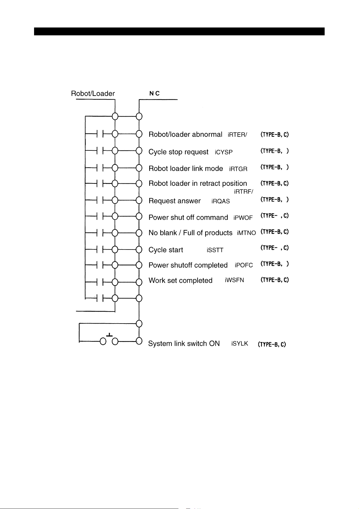
4-1. Inputs from the Robot/loader to the NC
5309-E P-3
ME61048R0200300040001
SECTION 1 ROBOT/LOADER INTERFACE TYPES
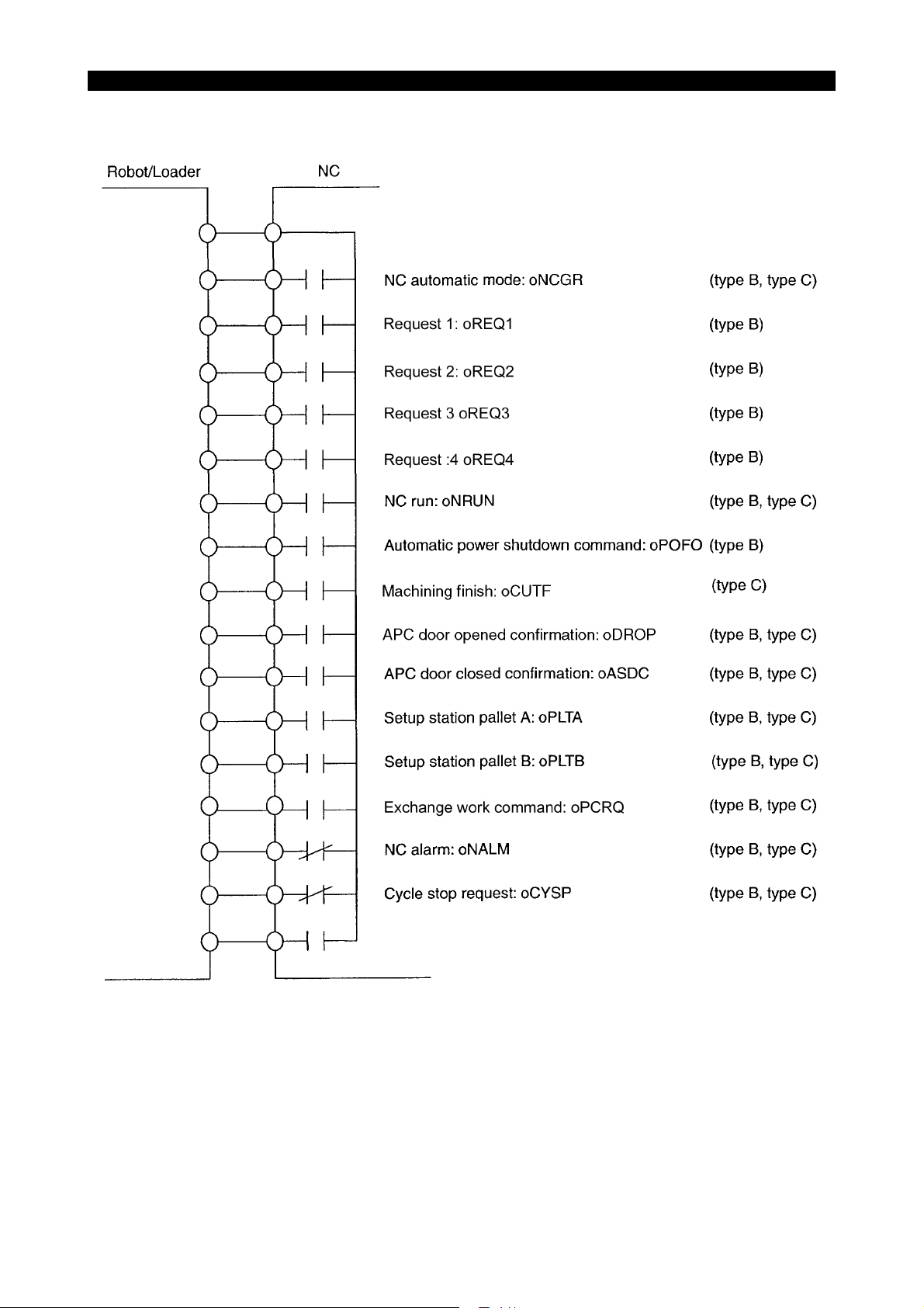
4-2. Outputs from the NC to the Robot/loader
5309-E P-4
ME61048R0200300050001
SECTION 1 ROBOT/LOADER INTERFACE TYPES
5. Description of Signals
5-1. Robot/loader Interface Type B
5-1-1. Inputs from the Robot/loader to the NC (Type B)
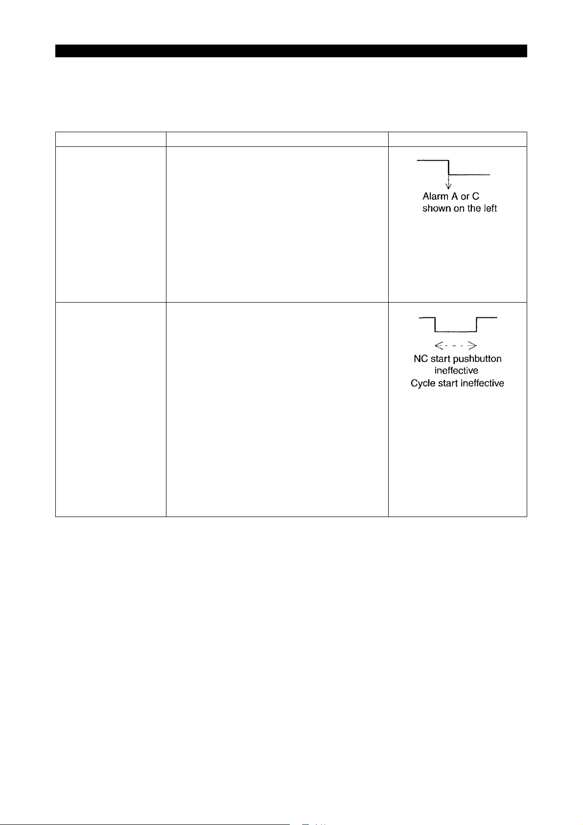
Signal name Description Signal level
Robot/loader abnormal
(iRTER/)
Robot/loader at retract
position
(iRTRF/)
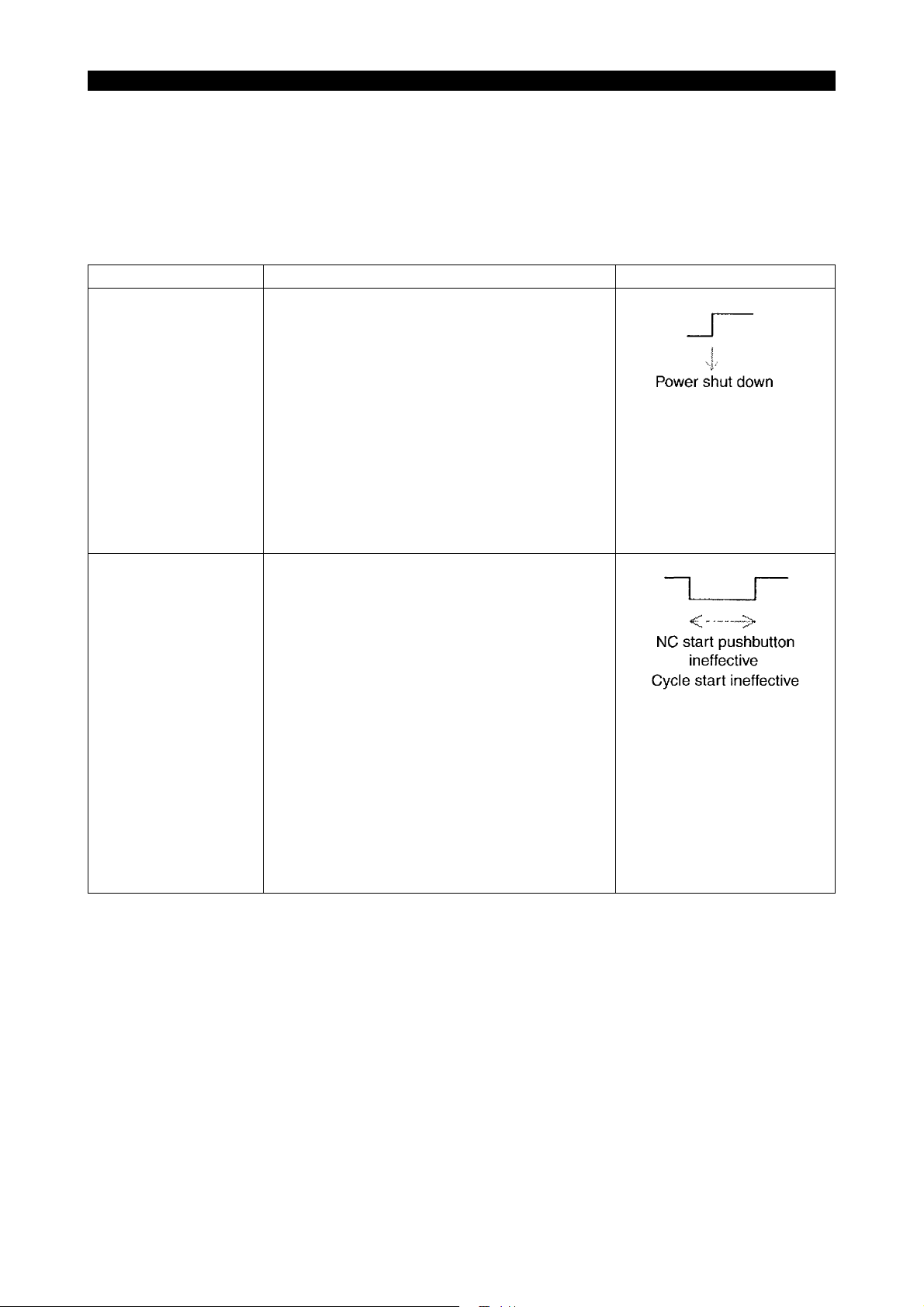
Either of the following alarms occurs when the
"system link switch" is turned ON and this signal is
turned OFF.
The alarm level is changeable with the appropriate parameter.
"8. Robot alarm is made alarm-C." of MC user
parameter ROBOT/LOADER I/F
"0": "1709 Alarm A external"
"1": "3718 Alarm C external"
However, this signal will not be monitored during
warm-up program start wait or during NC operation by warm-up program start.
The NC start pushbutton on the panel and the
"cycle start" command become ineffective when
the "system link switch" is turned ON and this signal is turned OFF.
5309-E P-5
The following alarm occurs when the NC start
pushbutton on the panel is pressed or the "cycle
start" signal is turned ON although NC start is ineffective.
The alarm remains displayed while the NC start
pushbutton on the panel is held down or the "cycle
start" signal is kept ON.
"4720 Alarm DNC start ineffective 12"
However, the above interlock becomes ineffective
when "2. Cycle start: STANDBY POS. I/L is made
ineffective" of MC user parameter ROBOT/
LOADER I/F is set to "1."
SECTION 1 ROBOT/LOADER INTERFACE TYPES
Signal name Description Signal level
No material/full-work
(iMTNO)
Preparation work completed
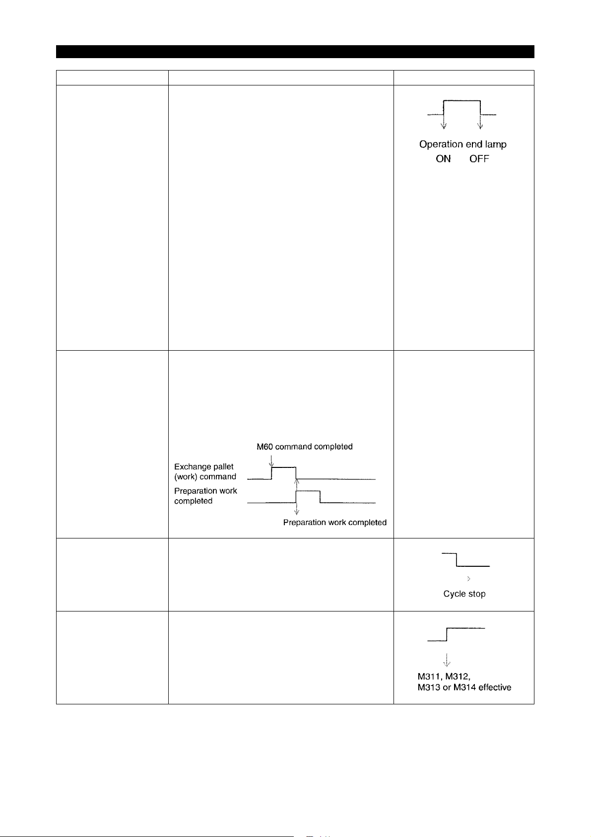
(iWSFN)
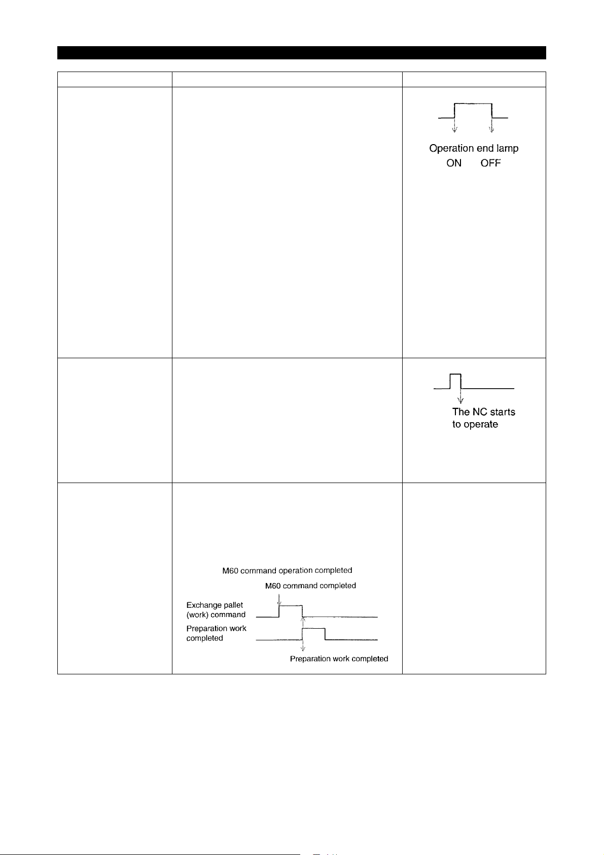
The operation end lamp lights while the "system
link switch" is kept ON, the operation end lamp is
effective (described below), and this signal is kept
ON.
MC user parameter
"0" is set at INDICATING LAMP (8. Operation end
lamp is made effect):
Operation end lamp is ineffective.
"1" is set at INDICATING LAMP (8. Operation end
lamp is made effect):
Operation end lamp is effective.
"5. Operation end lamp does not light on by M02/
M30" MC user parameter of ROBOT/LOADER I/F
"0":
The standard operation end lamp function also
becomes effective.
"1":
The standard operation end lamp function
becomes ineffective when the "system link switch"
is turned ON.
The "exchange pallet (work) command" is turned
OFF and work preparation is completed when this
signal is turned ON.
Note: The work preparation completed status will
be retained even if the NC is reset or the power is
turned ON or OFF.
[Time chart]
See the left figure.
5309-E P-6
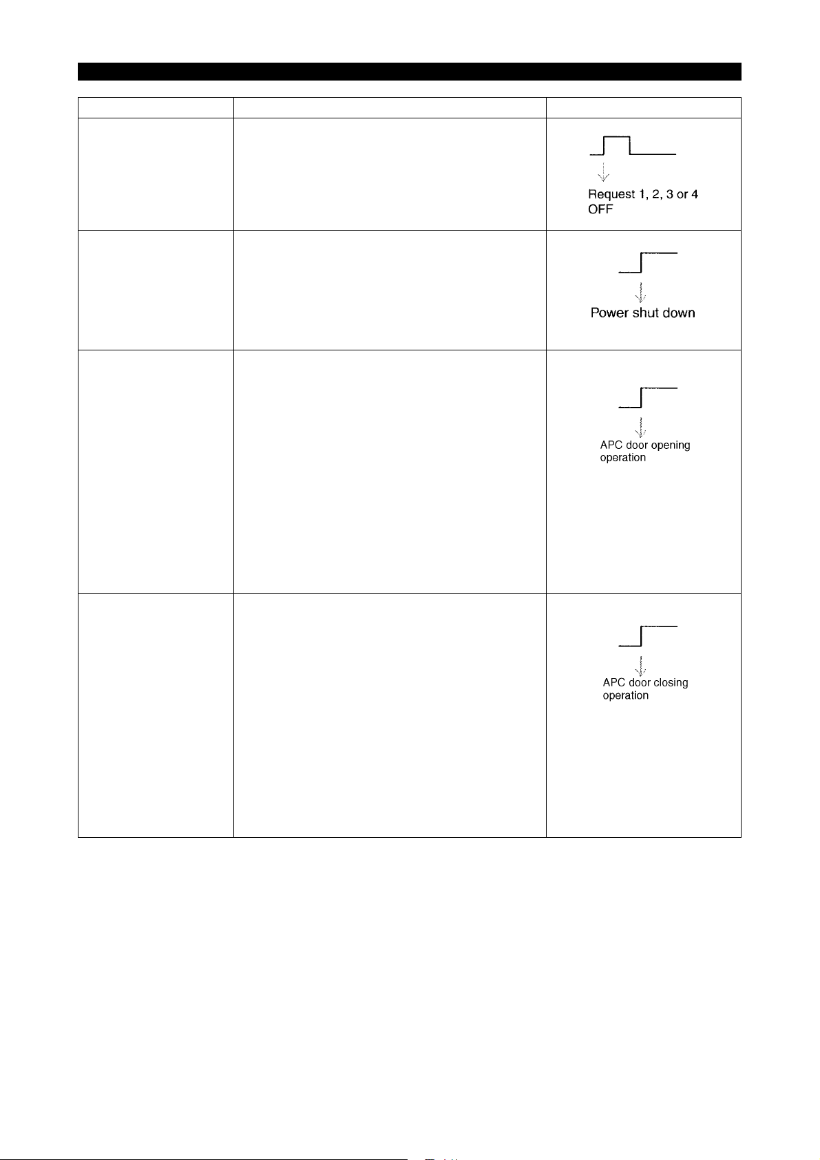
Cycle stop request
(iCYSP)
Robot automatic mode
(iRTGR)
The NC stops the ongoing cycle when this signal
is turned OFF in "automatic mode."
Request 1, 2, 3 or 4 becomes effective when this
signal is turned ON in "automatic mode."
If M311, M312, M313 or M314 is issued when this
signal is OFF, nothing will take place, and an
answer will be given back immediately.
SECTION 1 ROBOT/LOADER INTERFACE TYPES
Signal name Description Signal level
Request answer
(iRQAS)
The request output signal (request 1, 2, 3 or 4) is
turned OFF when this signal is turned ON in
"automatic mode."
Turn OFF this signal when the request output signal is turned OFF.
5309-E P-7
Automatic power shutdown completed
(iPOFC)
APC door open command
(iDROC)
APC door close command
(iDRCS)
The power will be shut down automatically when
this signal is turned ON with the "automatic power
shutdown command" output to the robot/loader in
"automatic mode."
For further information, see "Automatic Power
Shutdown Function".
On the machine without APC, the operation door
opens with this signal ON. This signal, however,
becomes ineffective under the following conditions:
• No link mode is established.
• The signal "Robot/loader retract position
iRTRF" is OFF.
(The robot/loader interface is ineffective when
"1" is set at the parameter 4. "DOOR MOVE:
STANDBY POS. I/L IS MADE INEFFECTIVE"
in the MC USER PARAMETER, ROBOTLOADER I/F).
• The machine is equipped with APC.
On the machine without APC, the operation door
closes with this signal ON. This signal, however,
becomes ineffective under the following conditions:
• No link mode is established.
• The signal "Robot/loader retract position
iRTRF" is OFF.
(The robot/loader interface is ineffective when
"1" is set at the parameter 4. "DOOR MOVE:
STANDBY POS. I/L IS MADE INEFFECTIVE"
in the MC USER PARAMETER, ROBOTLOADER I/F).
• The machine is equipped with APC.
SECTION 1 ROBOT/LOADER INTERFACE TYPES
5-1-2. Outputs from the NC to the Robot/loader (Type B)
Signal name Description Signal level
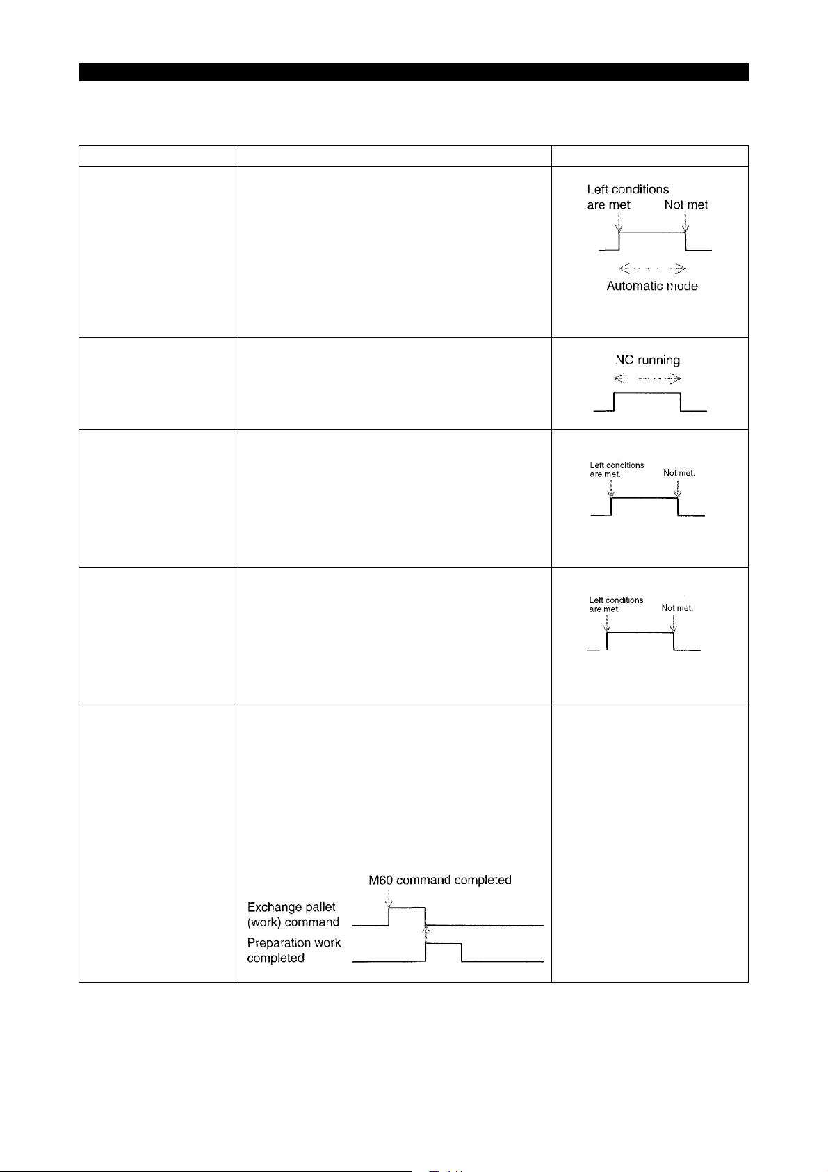
NC automatic mode
(oNCGR)
NC run
(oNRUN)
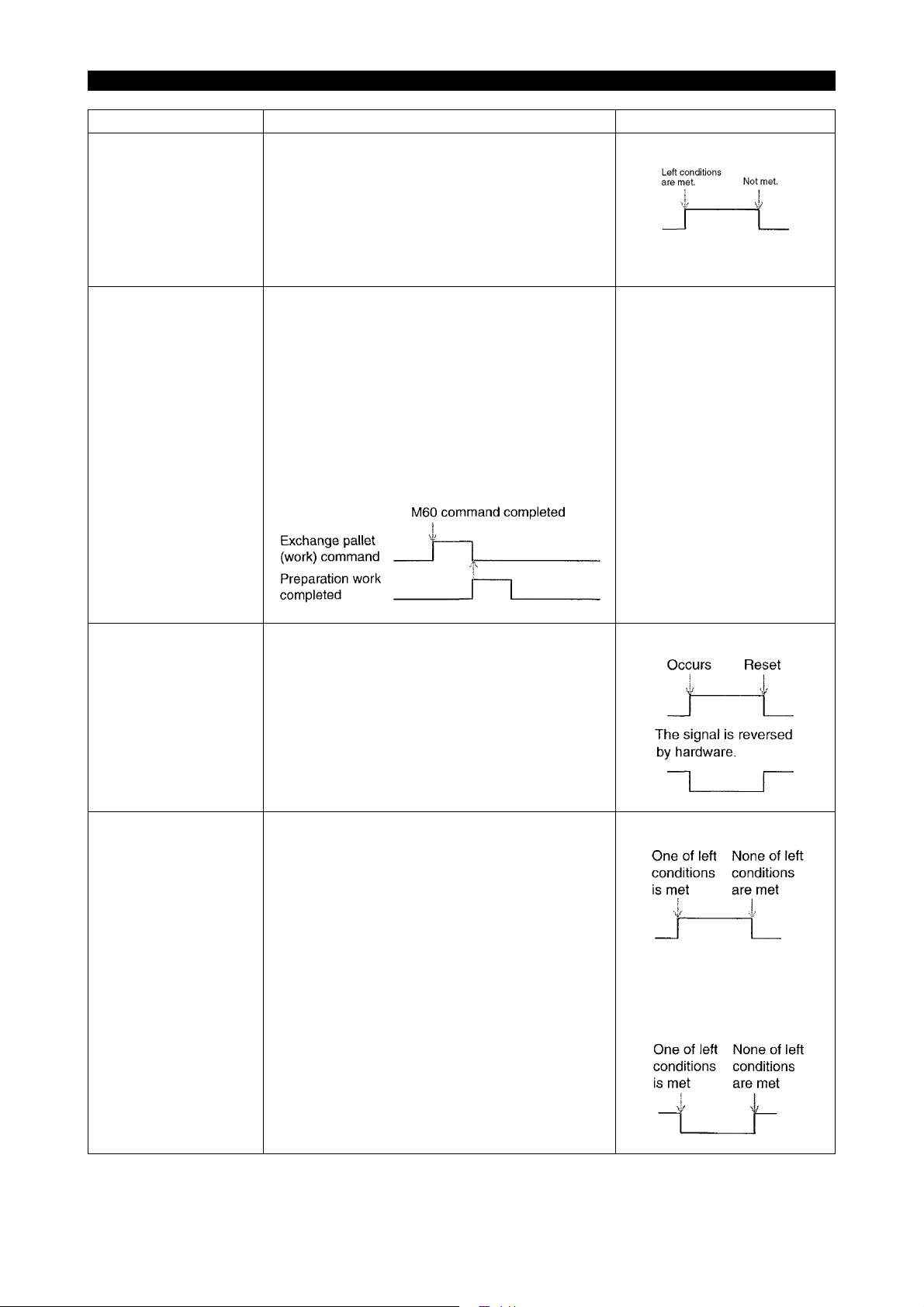
This signal is turned ON when the following conditions are met:
• Automatic operation mode
• "System link switch" ON
However, this signal will not be turned ON during
warm-up program start wait or during NC operation by warm-up program start.
This signal remains ON during NC operation.
5309-E P-8
A-pallet is outside of
M/C
(oPLTA)
B-pallet is outside of
M/C
(oPLTB)
Exchange pallet (work)
command
(oPCRQ)
This signal comes ON when all the following conditions are met:
• Pallet B mode is ON.
• Pallet A mode is ON when "1" is set at "B pal-
let in M/C side, when APC Seq. No.1" of the
machine user parameter CHUCK, SIT CONFIRMATION, TAILSOTCK.
This signal comes ON when all the following conditions are met:
• Pallet A mode is ON.
• Pallet B mode is ON when "1" is set at "B pal-
let in M/C side, when APC Seq. No.1" of the
machine user parameter CHUCK, SIT CONFIRMATION, TAILSOTCK.
This signal is turned ON upon completion of the
M60 command operation in automatic mode.
This signal is turned OFF with the "preparation
work completed" signal turned ON.
This signal will be retained even if the NC is reset
or the power is turned ON or OFF.
APC sequence No.
APC sequence No.
See the time chart shown on
the left.
[Time chart]
SECTION 1 ROBOT/LOADER INTERFACE TYPES
Signal name Description Signal level
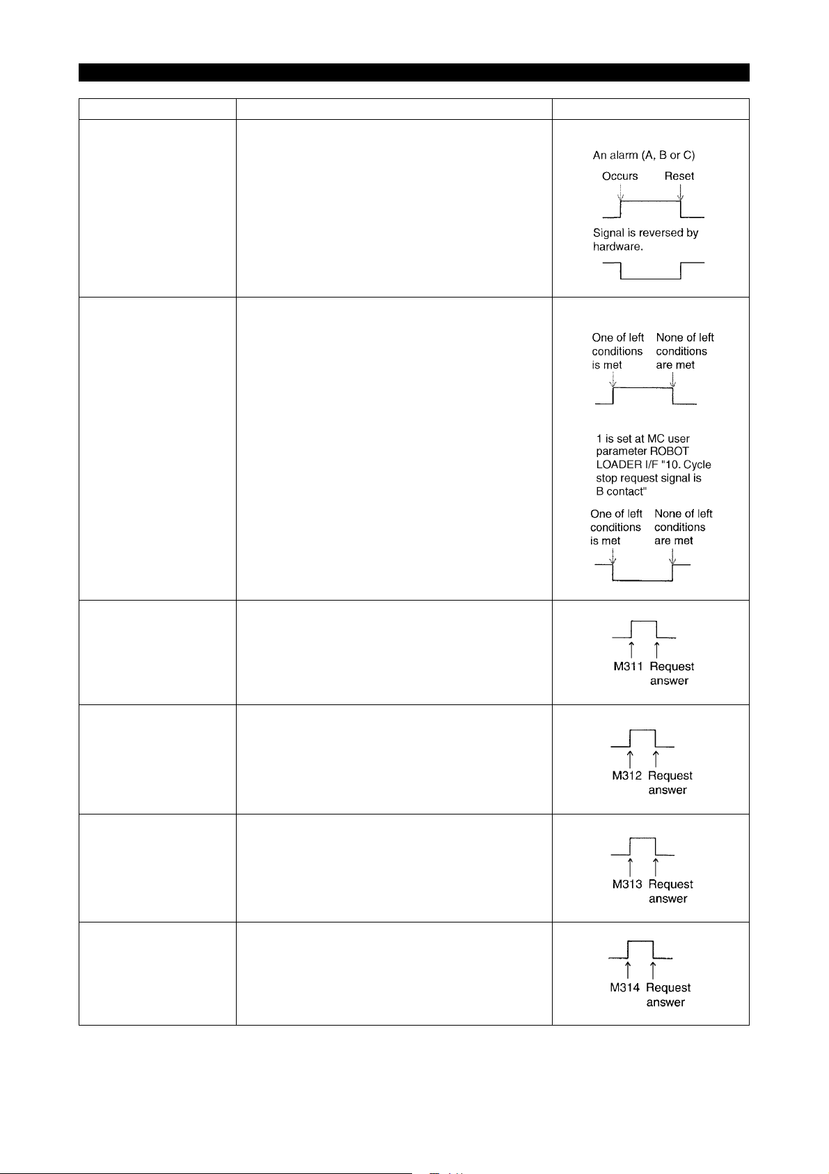
NC alarm
(oNALM)
This signal is usually OFF, but will be turned ON
when an alarm (A, B or C) occurs. NC reset will
turned OFF the signal again.
The signal will be reversed into a B contact by
hardware.
An alarm (A, B or C)
5309-E P-9
Cycle stop request
(oCYSP)
Request 1
(M311)
oREQ1
Request 2
(M312)
oREQ2
This signal is turned ON in one of the following
cases. The signal is turned OFF in other cases:
• When the count of the NC work counter is full.
• When the tool can no longer serve.
• When the "no material/full-work" signal is
turned ON with the "system link switch"
turned ON.
Whenever "1" is set at the MC user parameter
ROBOT LOADER I/F "10. Cycle stop request signal is B contact", this signal is turned ON. However, it will be turned OFF in one of the above
cases. (B contact output)
This signal is turned ON with the M311 command
when the "robot automatic mode" signal is turned
ON in "automatic mode."
An answer will be given back with the request
answer signal turned ON, and this signal will be
turned OFF.
Same as request 1, except that the M command is
M312.
Request 3
(M313)
oREQ3
Request 4
(M314)
oREQ4
Same as request 1, except that the M command is
M313.
Same as request 1, except that the M command is
M314.

SECTION 1 ROBOT/LOADER INTERFACE TYPES
Signal name Description Signal level
Automatic power shutdown command
oPOFO
This signal is turned ON after the time set by “6.
Power shutdown time” of MC user parameter
POWER SAVE/SHUTDOWN passes away if all of
the following conditions are met when the automatic power shutdown effective parameter (“3.
‘Automatic Power Shutdown’ is made effective” of
MC user parameter POWER SAVE/SHUTDOWN)
or automatic power shutdown ON/OFF switch is
turned ON in "automatic mode":
• Single block OFF in automatic operation
mode
• During existence of the machining cycle com-
pleted signal or alarm A, B or C
When "Automatic power shutdown MC alone" (“9.
Automatic power shutdown MC alone” of MC user
parameter ROBOT LOADER I/F) is "1", this signal
will not be output, and the power to the machine
will be shut down.
5309-E P-10
For further information, see "SECTION 7 WORK
SET ST AUTO DOOR SPEC."
SECTION 1 ROBOT/LOADER INTERFACE TYPES
The conditions for outputting the operation door open/close confirmation signals vary with the specifications as described below:
a. With the operation door auto open/close spec
For details regarding the operation door auto open/close spec, refer to "Section 4 Operation
Door Auto Open/Close Spec".
Signal name Description Signal level
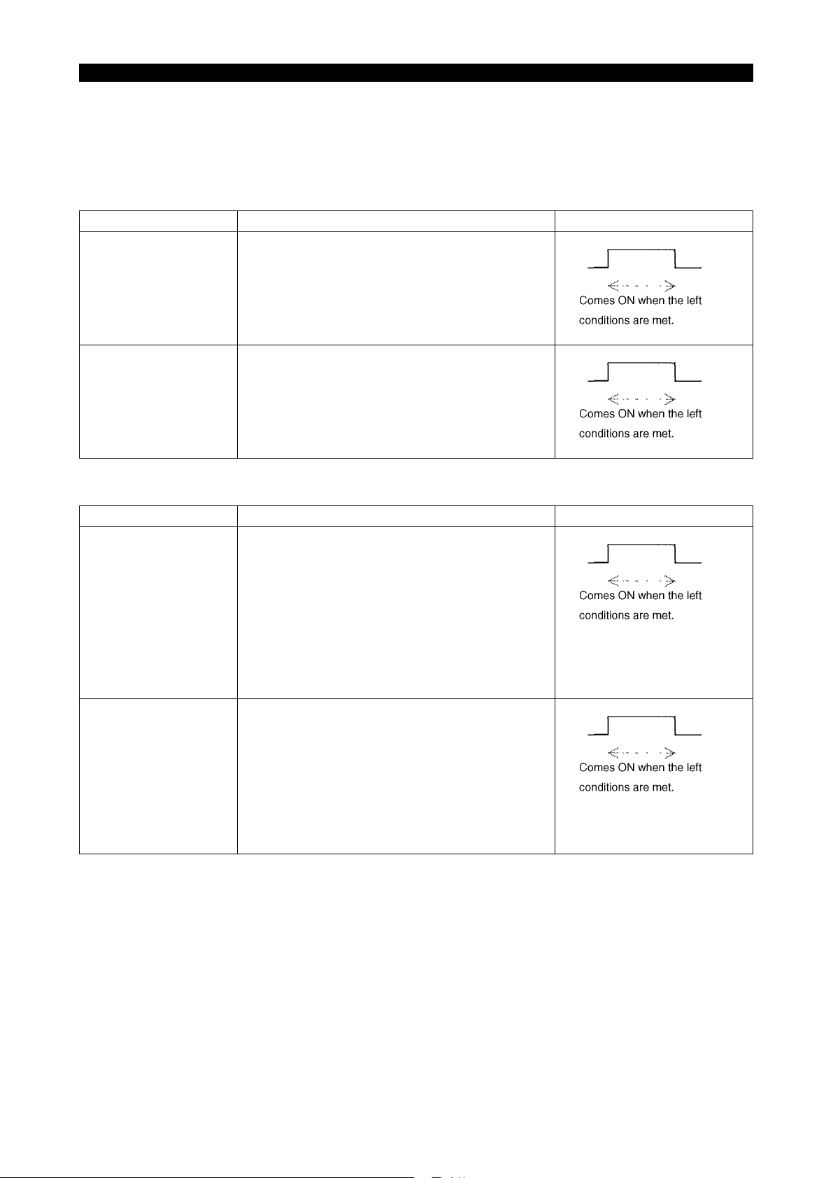
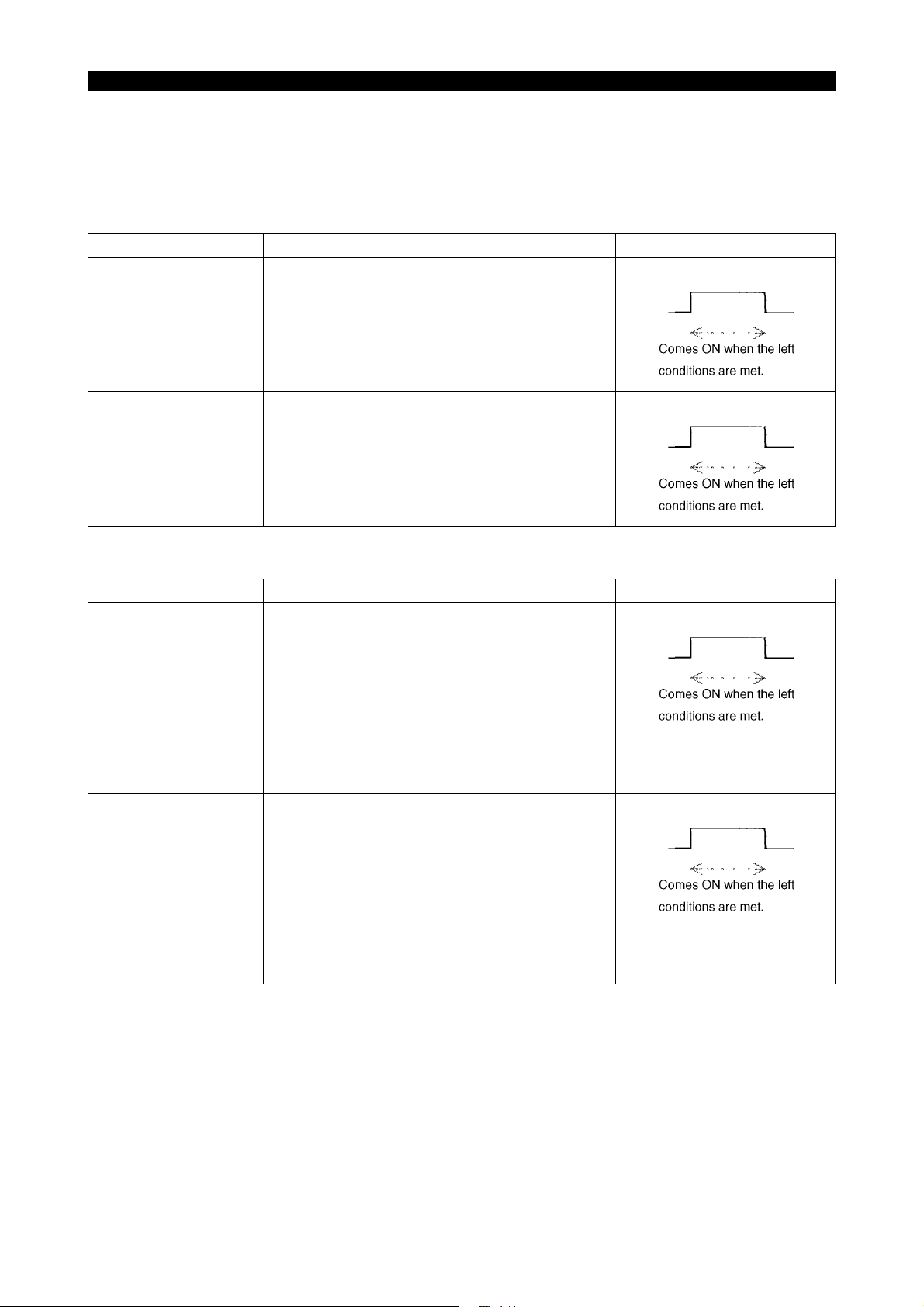
Operation door open
(oDROP)
This signal comes ON when the following conditions are met:
• Operation door open output ON
• Operation door open confirmation ON
• Operation door close confirmation OFF
Operation door close
(oDRCP)
This signal comes ON when the following conditions are met:
• Operation door close output ON
• Operation door close confirmation ON
• Operation door open confirmation OFF
5309-E P-11
b. Without the operation auto door spec
Signal name Description Signal level
Operation door open
(oDROP)
This signal comes ON when the following conditions are met:
• Operation door open confirmation ON *
• Operation door close confirmation OFF
* Without the operation door auto open/close, The
signal "Operation door open confirmation" is provided as option.
Operation door close
(oDRCP)
This signal comes ON when following conditions
are met:
• Front door open confirmation ON
• Front door close confirmation OFF*
* Without the operation door auto open/close
spec, The signal "Operation door close confirmation" is provided as option.
SECTION 1 ROBOT/LOADER INTERFACE TYPES
5-2. Robot/loader Interface Type C
5-2-1. Inputs from the Robot/loader to the NC (Type C)
Signal name Description Signal level
Robot/loader abnormal
(iRTER/)
Robot/loader at retract
position
(iRTRF/)
Either of the following alarms occurs when the
"system link switch" is turned ON and this signal is
turned OFF. The alarm level is changeable with
the appropriate parameter.
"8. Robot alarm is made alarm C." of MC user
parameter ROBOT LOADER I/F
"0": "1709 Alarm A external"
"1": "3718 Alarm C external"
However, this signal will not be monitored during
warm-up program start wait or during NC operation by warm-up program start.
The NC start pushbutton on the panel and the
"cycle start" command become ineffective when
the "system link switch" is turned ON and this signal is turned OFF.
5309-E P-12
The following alarm occurs when the NC start
pushbutton on the panel is pressed or the "cycle
start" signal is turned ON although NC start is ineffective.
The alarm remains displayed while the NC start
pushbutton on the panel is held down or the "cycle
start" signal is kept ON.
"4720 Alarm D NC start ineffective 12"
However, the above interlock becomes ineffective
when "2. Cycle start: STANDBY POS. I/L is made
ineffective" of MC user parameter ROBOT
LOADER I/F is "1".

SECTION 1 ROBOT/LOADER INTERFACE TYPES
Signal name Description Signal level
Automatic power shutdown command
(iPWOF)
The power is automatically shut down after the
time set by "6. Automatic power shutdown timer"
of MC user parameter POWER SAVE/SHUTDOWN passes away if all of the following conditions are met when this signal is turned ON in
"automatic mode":
• Single block OFF in automatic operation
mode
• During existence of the machining cycle com-
pleted signal or alarm A, B or C
This signal is not affected by the automatic power
shutdown effective switch ("3. 'Automatic Power
Shutdown' is made effective" of MC user parameter POWER SAVE/SHUTDOWN) or automatic
power shutdown ON/OFF switch.
When "6. Automatic Power shutdown switch is
made effective" of MC user parameter ROBOT
LOADER I/F is "1", this function becomes effective only when the automatic power shutdown
effective switch ("3. 'Automatic Power Shutdown'
is made effective" of MC user parameter POWER
SAVE/SHUTDOWN) is set to "1" or the automatic
power shutdown ON/OFF switch is set to automatic power shutdown ON.
When "4. Alarm is added as a requirement for
Shutdown" of MC user parameter POWER SAVE/
SHUTDOWN is "0", the occurrence of an alarm A
or B is not included in the automatic power shutdown conditions.
5309-E P-13
For further information, see "SECTION 7 WORK
SET ST AUTO DOOR SPEC."
SECTION 1 ROBOT/LOADER INTERFACE TYPES
Signal name Description Signal level
No material/full-work
(iMTNO)
Cycle start
(iSSTT)
The operation end lamp lights while the "system
link switch" is kept ON, the operation end lamp is
effective (described below), and this signal is kept
ON.
MC user parameter
"0" is set at INDICATING LAMP, "8. Operation end
lamp is made effect":
Operation end lamp is ineffective.
"1" is set at INDICATING LAMP, "8. Operation end
lamp is made effect":
Operation end lamp is effective.
MC user parameter
"5. Operation end lamp does not light on by M02/
M30" of ROBOT LOADER I/F
"0":
The standard operation end lamp function also
becomes effective.
"1":
The standard operation end lamp function
becomes ineffective when the "system link switch"
is turned ON.
The NC starts to operate on the falling edge of this
signal when all of the following conditions are met:
5309-E P-14
Preparation work completed
(iWSFN)
• "Automatic mode"
• "Robot/loader at retract position" ON
(The "robot/loader at retract position interlock
be-comes ineffective when "2. Cycle start:
STANDBY POS. I/L is made ineffective" of
MC user parameter ROBOT LOADER I/F is
"1".)
The "exchange pallet (work) command" is turned
OFF and work preparation is completed when this
signal is turned ON.
Note: The work preparation completed status will
be retained even if the NC is reset or the power is
turned ON or OFF.
See the figure shown on the
left.

SECTION 1 ROBOT/LOADER INTERFACE TYPES
Signal name Description Signal level
APC door open command
(iDROC)
The APC door opens when this signal comes ON.
However, the door does not open in any of the following cases:
• The link mode is not established.
• The APC door opening M command is being
executed.
• The APC cycle is being conducted or the
APC is not in the start position.
• An alarm A is occurring.
• The power save mode is established.
• Machine lock is ON.
• The robot/loader retract position signal
iRETRF_b is OFF.
(This interlock signal is ignored when "1" is
set at "4. Door move: STANDBY POS. I/L is
made ineffective" of the machine user parameter ROBOT LOADER I/F).
5309-E P-15
APC door close command
(iDRCS)
For details, refer to SECTION 7 "WORK SET ST
AUTO DOOR SPEC."
The APC door opens when this signal comes ON.
However, the door does not open in any of the following cases:
• The link mode is not established.
• The APC door opening M command is being
executed.
• The APC cycle is being conducted or the
APC is not in the start position.
• An alarm A is occurring.
• The power save mode is established.
• Machine lock is ON.
• The robot/loader retract position signal
iRETRF_b is OFF.
(This interlock signal is ignored when "1" is
set at "4. Door move: STANDBY POS. I/L is
made ineffective" of the machine user parameter ROBOT LOADER I/F).
For details, refer to SECTION 7 "WORK SET ST
AUTO DOOR SPEC."

SECTION 1 ROBOT/LOADER INTERFACE TYPES
5-2-2. Outputs from the NC to the Robot/loader (Type C)
Signal name Description Signal level
NC automatic mode
(oNCGR)
NC running
(oNRUN)
This signal is turned ON when the following conditions are met:
• Automatic operation mode
• "System link switch" ON
However, this signal will not be turned ON during
warm-up program start wait or during NC operation by warm-up program start.
This signal remains ON during NC operation.
5309-E P-16
Machining cycle completed
(oCFUTF)
This signal is turned ON upon completion of NC
machining (at the end of M02, M30 or schedule
program).
This signal is turned OFF on the rising edge of the
cycle star switch and NC run signal.
This signal will be retained even if the NC is reset
or the power is turned ON or OFF.
This signal does not come ON with M02 or M30
by warm-up program start. This signal does not go
OFF by warm-up program start because it is not
regarded as NC running.
[Machining time chart]
See the time chart shown on
the left.
A-pallet is outside of
M/C
(oPLTA)
This signal comes ON when all the following conditions are met:
• Pallet B mode is ON.
• Pallet A mode is ON when "1" is set at "B pal-
let in M/C side, when APC Seq. No.1" of the
machine user parameter CHUCK, SIT CONFIRMATION, TAILSOTCK.
APC sequence No.
SECTION 1 ROBOT/LOADER INTERFACE TYPES
Signal name Description Signal level
B-pallet is outside of
M/C
(oPLTB)
This signal comes ON when all the following conditions are met:
• Pallet A mode is ON.
APC sequence No.
• Pallet B mode is ON when "1" is set at "B pal-
let in M/C side, when APC Seq. No.1" of the
machine user parameter CHUCK, SIT CONFIRMATION, TAILSOTCK.
Exchange pallet (work)
command
(oPCRQ)
This signal is turned ON upon completion of the
M60 command operation in automatic mode. This
signal is turned OFF with the "preparation work
completed" signal turned ON.
This signal will be retained even if the NC is reset
or the power is turned ON or OFF.
This signal will be turned OFF in a mode other
than automatic mode.
[Time chart]
See the time chart shown on
the left.
5309-E P-17
NC alarm
(oNALM)
Cycle stop request
(oCYSP)
This signal is usually OFF, but will be turned ON
when an alarm (A, B or C) occurs. NC reset will
turn OFF the signal again.
The signal will be reversed into a B contact by
hardware. The signal is reversed by hardware.
This signal is turned ON in one of the following
cases.
The signal will be turned OFF in none of the following cases:
• When the count of the NC work counter is full.
• When the tool can no longer serve.
• When the "no material/full-work" signal is
turned ON with the "system link switch"
turned ON.
Whenever "10. Cycle stop request signal is B contact" of MC user parameter ROBOT LOADER I/F
is "1", this signal is turned ON. However, it will be
turned OFF in one of the above cases. (B contact
output)
An alarm (A, B or C)
"1" is set at MC user parameter ROBOT LOADER I/F"10.
Cycle stop request signal is B
contact".

SECTION 1 ROBOT/LOADER INTERFACE TYPES
Signal name Description Signal level
Work condition 1
oREQ1
Work condition 2
oREQ2
Work condition 3
oREQ3
Work condition 4
oREQ4
This signal comes ON when M311 is issued
(immediate answer).
This signal goes OFF at the rising edge of the
cycle start signal or NC running signal. (The OFF
conditions are the same with those of the machining end signal.)
This signal remains effective after NC reset or
power ON/OFF.
This signal comes ON when M312 is issued
(immediate answer).
This signal goes OFF at the rising edge of the
cycle start signal or NC running signal. (The OFF
conditions are the same with those of the machining end signal.)
This signal remains effective after NC reset or
power ON/OFF.
This signal comes ON when M313 is issued
(immediate answer).
This signal goes OFF at the rising edge of the
cycle start signal or NC running signal. (The OFF
conditions are the same with those of the machining end signal.)
This signal remains effective after NC reset or
power ON/OFF.
This signal comes ON when M314 is issued
(immediate answer).
This signal goes OFF at the rising edge of the
cycle start signal or NC running signal. (The OFF
conditions are the same with those of the machining end signal.)
This signal remains effective after NC reset or
power ON/OFF.
5309-E P-18
SECTION 1 ROBOT/LOADER INTERFACE TYPES
The conditions for outputting the APC door open/close confirmation signals vary with the specifications as described below:
a. With the work set ST auto door spec
For details regarding the specifications for the setup station door auto open/close, refer to "Section 7 Work Set ST Auto Door Spec"
Signal name Description Signal level
APC door open
(oDROP)
This signal comes ON when the following conditions are met:
• APC door open output ON
• APC door open confirmation ON
• APC door close confirmation OFF
5309-E P-19
APC door close
(oDRCP)
This signal comes ON when the following conditions are met:
• APC door close output ON
• APC door close confirmation ON
• APC door open confirmation OFF
b. Without the work set ST auto door spec
Signal name Description Signal level
APC door open
(oDROP)
This signal comes ON when the following conditions are met:
• APC door open confirmation ON *
• APC door close confirmation OFF
* Without work set ST auto spec, the APC door
open confirmation is provided as an optional
specification.
APC door close
(oDRCP)
This signal comes ON when following conditions
are met:
• APC door open confirmation ON *
• This signal comes ON when APC door close
confirmation is ON.
* Without work set ST auto spec, the APC door
open confirmation is provided as an optional
specification.
 Loading...