


Program construction
Program:
The most controller are using as a job control
language the symbols from the DIN66025.
After this the partprogram are contains a
sequence of lines.
A line contains several words.
A word contains a letter and a number.
Part program:
N10 G50 S2500
N20 G0 X500 Z500
N30 G0 X50 Z2 T0101 G97 S2500 M3 M8
24
OKUMA

Line:
N20 G0 X500 Z500
Word:
X 500
Address Number
The separate line contains:
• Program technical information.
• Geometrical information.
• Technical information.
24
OKUMA

Program technical information:
For the execution of the program are necessary.
For example : + Plus
— Minus
. decimal point
Geometrical information.
Means motion of some axis in the machine, the
word for the motion is from that address G
( Engl. Word for Go ) and some numbers behind.
The most important G commands are:
G00 positioning
G01 linear interpolation
24
OKUMA

Technical information.
F = Feedrate
T = Tool
S = Spindlespeed
M = additional function
For example:
F – command = F0.25 ( mm/rpm )
T – command = T0101 ( Tool no. 1 )
S – command = S1000 ( 1000 rpm )
M – command = M03 ( spindle direction CW )
25
OKUMA

Main Address Characters
Main Address Characters
•N Block Number
• G Preparatory Function (See List)
• X Diameter Value
• Z Length Value
• F Feedrate (mm/min or mm/rev)
• (or Dwell time in seconds)
• S Spindle Speed (m/min or rev/min)
• T Turret Station/Offset Number
• M Miscellaneous Function (See List)
M––
M
M – function are help function, just to
switch on some additional function, e.g.
coolant on or off, C –axis on or off.
Function
Function
25
OKUMA
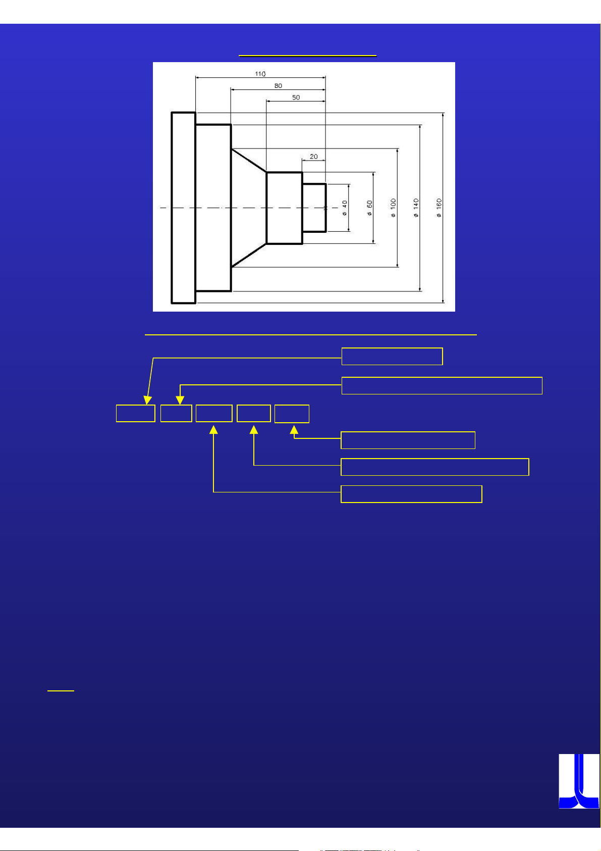
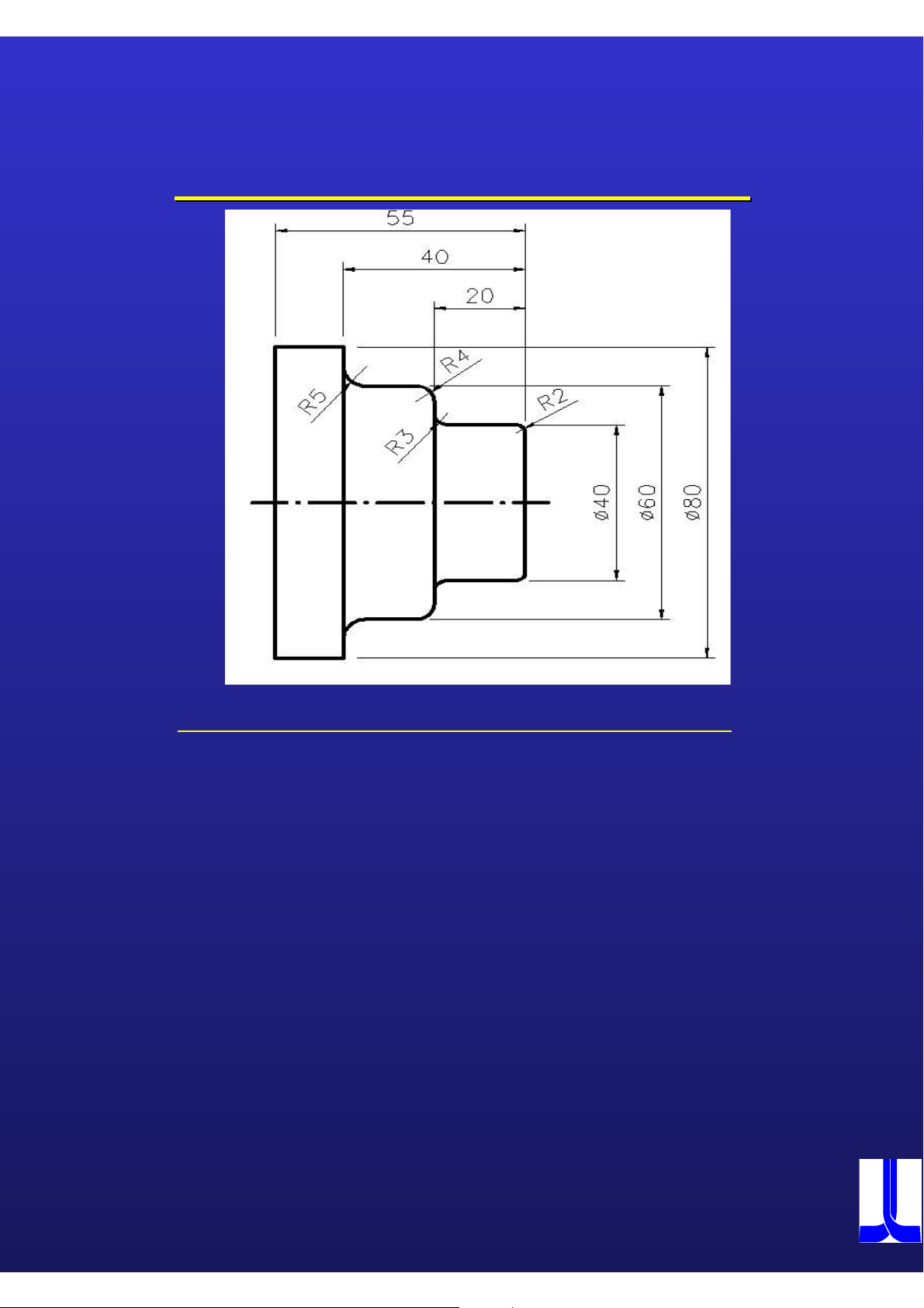
Lesson with G01
Lesson with G01
Program construction for 2 axis lathe machine
G50 S4500
G00 X500 Z500
G00 X0 Z2 T0101 G96 S250 M03 M08
G01 Z0 F0.15
G01 X40
G01 Z-20
G01 X60
G01 Z-50
G01 X100 Z-80
G01 X140
G01 Z-110
G01 X160
G01 Z-130
G00 X500 Z500 M09
M02
Tool command
G Code for constant cutting speed
M- code coolant on
M-code for spindle direction
Cutting speed in m/min
Note
The G00 command means that the machine will move with rapid feedrate , the rapid feedrate
is dependent on the machine. The unit for rapid feedrate is m/min.
The G01 command means that the machine will move with feedrate, therefore it is necessary
to program in the first line with G01 a feedrate command.
The address for feedrate is ”F ” for example F0.25 = 0.25mm by one rotation of the spindle
OKUMA
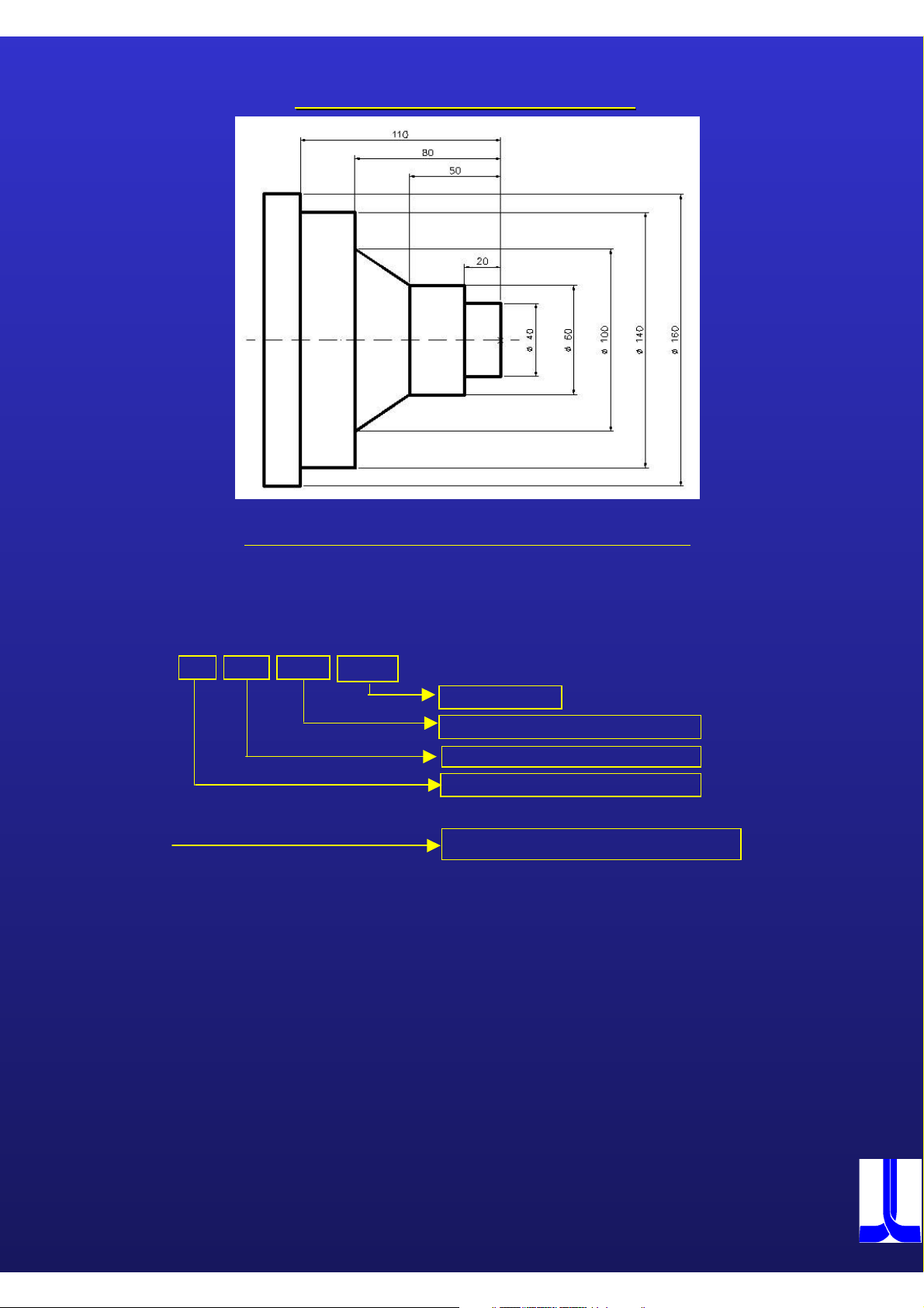
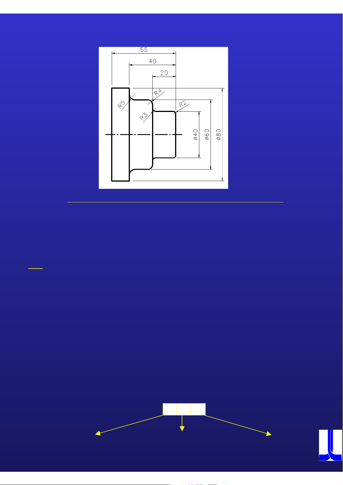
Lesson with G85 Lap cycle
Lesson with G85 Lap cycle
Program construction for G85 Lap cycle
G50 S4500
G00 X500 Z500
G00 X160 Z2 T0101 G96 S250 M03 M08
G85 NAP1 D5 U0.5 W0.1 F0.35
F = Feedrate
W = Stock removal in Z
U = Stock removal in X
D = Cuttingdepth in diameter
NAP1 G81 G81 = Cutting direction in Z - axis
G01 X0 Z0
X40
Z-20
X60
Z-50
X100 Z-80
X140
Z-110
X160
G80
G00 X500 Z500 M09
M02
27
OKUMA

Exercise G85 /G81
Exercise G85 /G81
28 ( 29 )
OKUMA
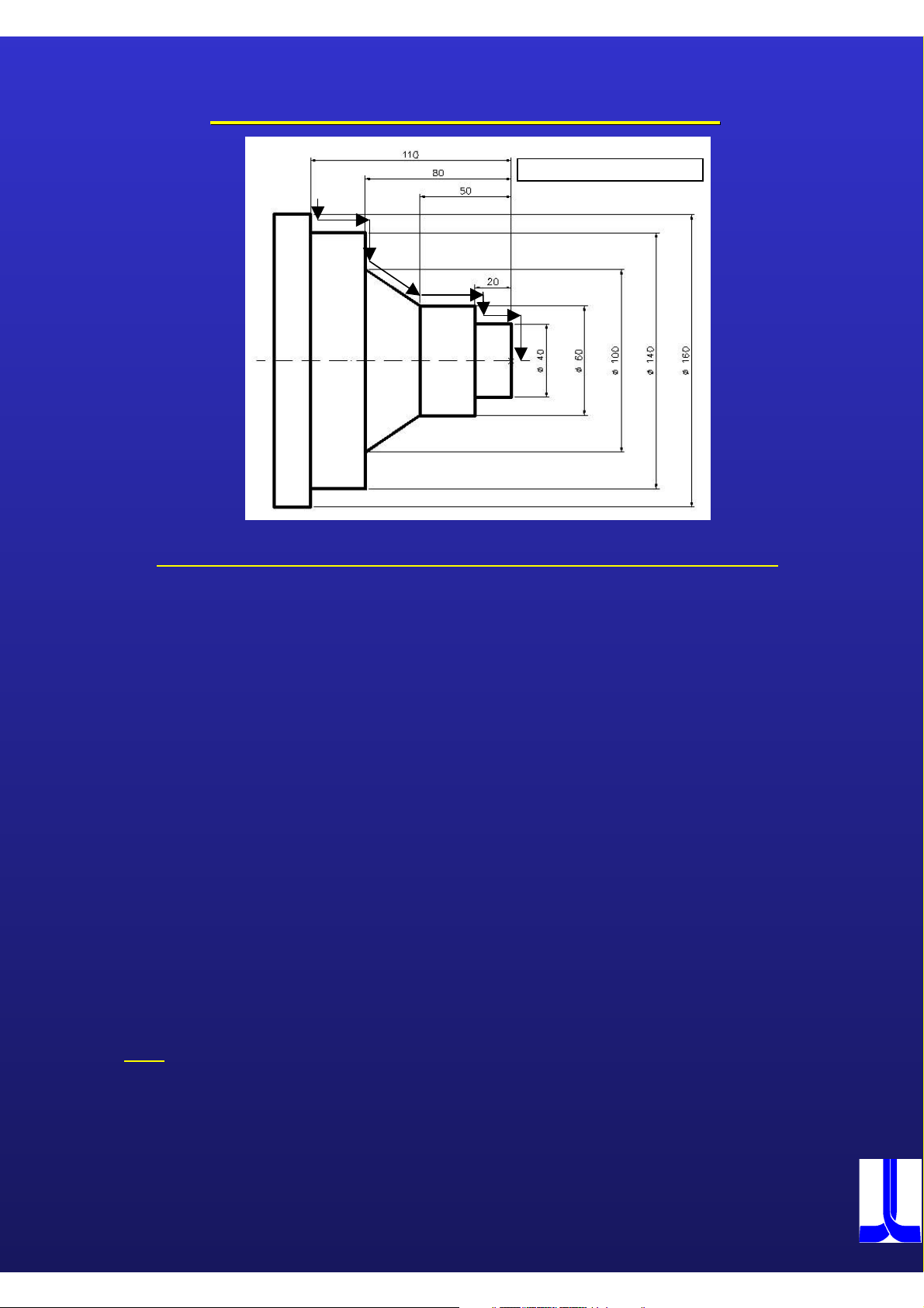
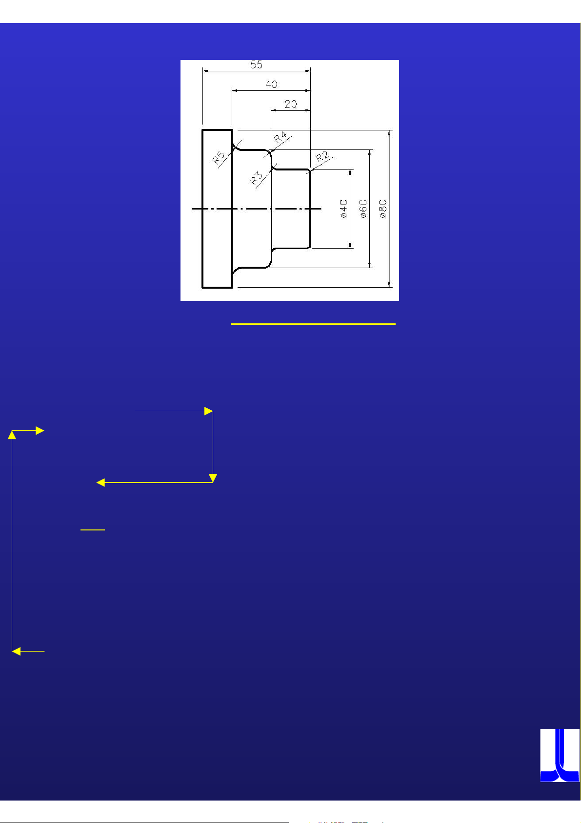
Lesson G85 Lap Cycle in X --
Lesson G85 Lap Cycle in X
Blank material D= 162
Direction
Direction
Program construction for G85 Lap cycle in X -Direction
G50 S4500
G00 X500 Z500
G00 X162 Z2 T0101 G96 S250 M03 M08
G85 NAP1 D4 U0.5 W0.1 F0.35
NAP1 G82
G0 Z-110
G1 X140
G1 Z-80
G1 X100
G1 X60 Z-50
G1 Z-20
G1 X40
G1 Z0
G80
G00 X500 Z500
M02
Note
Please consider, the G82 contour description start from the spindle and will go in
direction of the tailstock.
30
OKUMA

Exercise G85 / G82
Exercise G85 / G82
31 ( 32 )
OKUMA

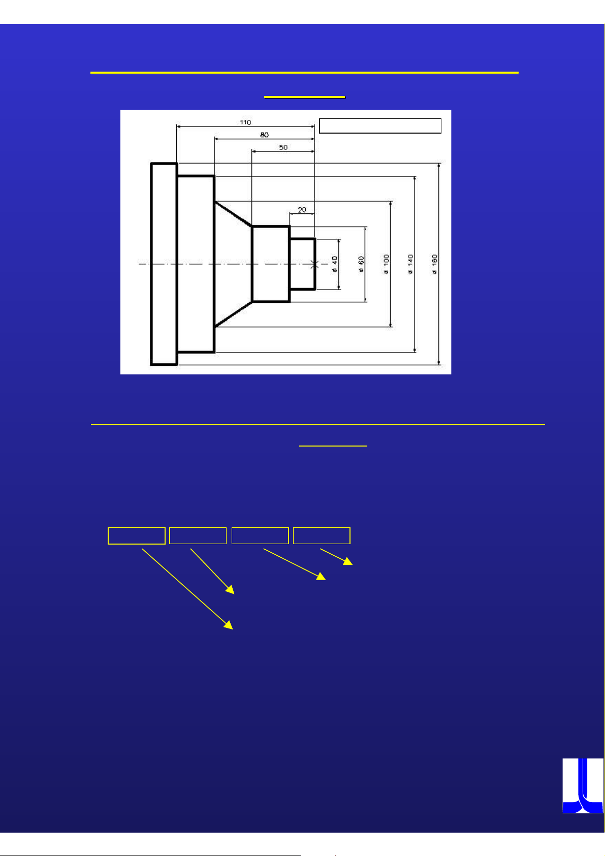
Lesson G85 Lap Cycle in Z ––
Lesson G85 Lap Cycle in Z
contour definition
contour definition
Blank material D= 162
direction with blank
direction with blank
G50 S4500
G00 X500 Z500
G00 X165 Z2 T0101 G96 S250 M03 M08
G85 NAP1 D4 U0.5 W0.1 F0.35
NAP1 G83 G – Code for blank material
G0 X0 Z5
G1 X45
G1 Z-15
G1 X65 Z-45
G1 X105 Z-75 Blank material definition
G1 X145
G1 Z-105
G1 X170
G81 G – Code for longitudinal shape designation
G0 X0 Z2
G1 Z0
G1 X40
G1 Z-20
G1 X60 Z-50 Finish shape
G1 X100 Z-80
G1 X140
G1 Z-110
G1 X160
G1 Z-130
G1 X162
G80
G00 X500 Z500
M02 33
OKUMA

Exercise G85 / G83
)
Exercise G85 / G83
34 ( 35
OKUMA
Lesson G85 Lap Cycle with G84 changing cutting
Lesson G85 Lap Cycle with G84 changing cutting
condition
condition
Blank material D= 162
Program construction for G85 Lap cycle with changing cutting
condition
G50 S4500
G00 X500 Z500
G00 X165 Z2 T0101 G96 S250 M03 M08
G85 NAP1 D4 U0.5 W0.1 F0.35
$ G84
NAP1 G81
G00 X0 Z2
G01 Z0 F0.1
G01 X40
G01 Z-20
G01 X60
G01 Z-50
G01 X100 Z-80
G01 X140
XA=100 ZA=2 DA=1 FA=0.1
Feedrate
Cutting depth
Start point in Z for reduction of
the cutting condition
Start point in X for reduction of
the cutting condition
G01 Z-110
G01 X160
G80
G00 X500 Z500
M02
OKUMA

Lesson G87 Lap Cycle finish cutting cycle
Lesson G87 Lap Cycle finish cutting cycle
Blank material D= 162
Program construction for G87 finish cutting cycle
Program construction for G87 finish cutting cycle
G50 S4500
G00 X500 Z500
( OD Rough )
G00 X162 Z2 T0101 G96 S250 M03 M08
G85 NAP1 D4 U0.5 W0.1 F0.35 G84 XA=100 ZA=2 DA=1 FA=0.1
NAP1 G81
G00 X0 Z2
G01 Z0 F0.1
G01 X40
G01 Z-20
G01 X60 Z-50
G01 X100 Z-80
G01 X140
G01 Z-110
G01 X160
G01 Z-130
G80
G00 X500 Z500
( OD Finish )
G00 X165 Z2 T0202 G96 S250 M03 M08
G87 NAP1
G00 X500 Z500
M02
37
OKUMA
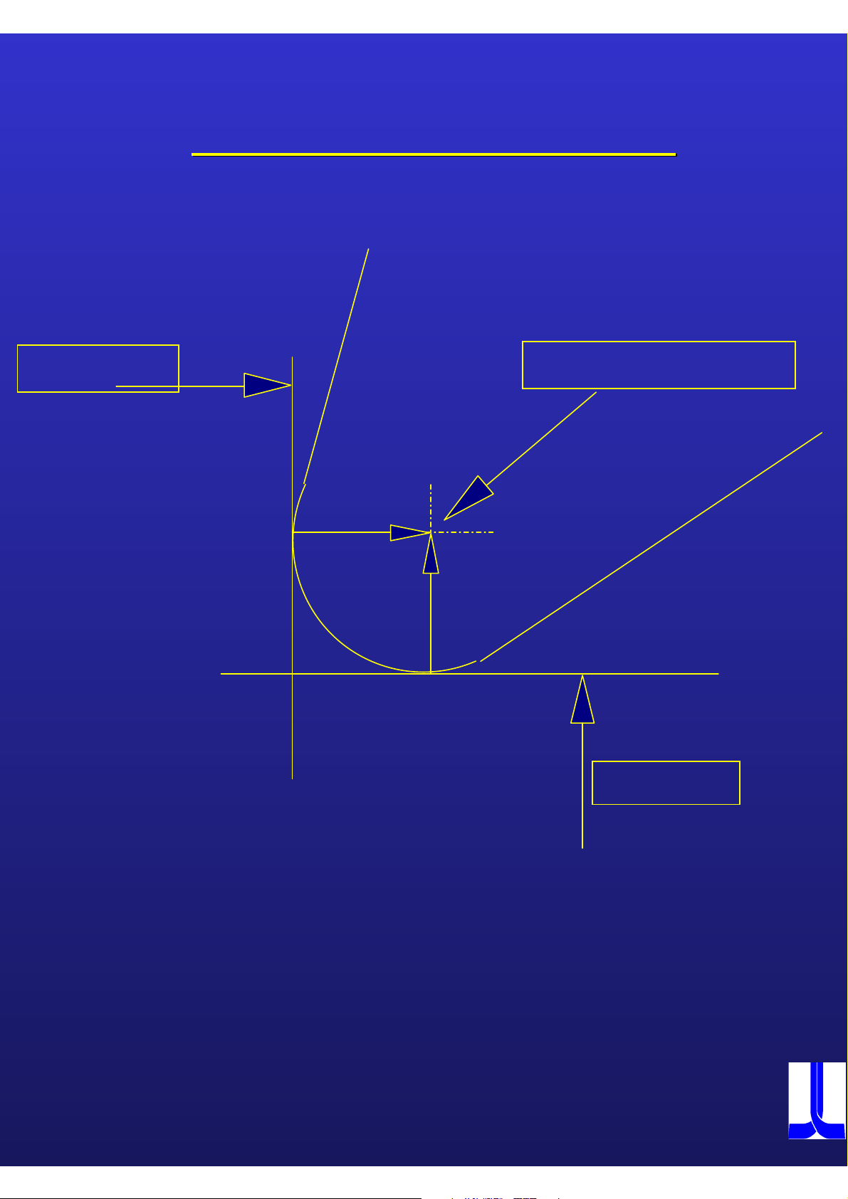
Lesson G76 automatic rounding
Lesson G76 automatic rounding
Program construction for G76 automatic rounding
G50 S4500
G00 X500 Z500
G00 X165 Z2 T0101 G96 S250 M03 M08
G00 X0
G01 Z0 F0.1
G01 G76 X40 L2
G01 G76 Z-20 L3
G01 G76 X60 L4
G01 G76 Z-40 L5
G01 X85
G00 X500 Z500 M09
M02
38
OKUMA

Lesson G75 automatic chamfering
Lesson G75 automatic chamfering
Program construction for G75 automatic chamfering
G50 S4500
G00 X500 Z500
G00 X165 Z2 T0101 G96 S250 M03 M08
G00 X0
G01 Z0 F0.1
G01 G75 X40 L2
G01 G75 Z-20 L3
G01 G75 X60 L4
G01 G75 Z-40 L5
G01 X85
G00 X500 Z500 M09
M02
39
OKUMA

Lesson Taper cutting by angle designation and G76
Lesson Taper cutting by angle designation and G76
function
function
Program construction for Taper cutting by angle designation and
G76 function
G50 S4500
G00 X500 Z500
G00 X165 Z2 T0101 G96 S250 M03 M08
G00 X0
G01 Z0 F0.1
G01 X40
G01 G76 Z-17.5 A170 L30
G01 G76 Z-37.5 A150 L5
G01 X85
G01 X105 A120
G01 Z-55
G01 X110
G00 X500 Z500 M09
M02
40
OKUMA

A VALUE
DIRECT ANGLE COMMAND
135°
-225°
180°
-180°
90°
-270°
START POINT
OF ANGLE
0°
41
270°
-90°
OKUMA

Lesson Taper cutting
Lesson Taper cutting
by
angle designation and G76
by
angle designation and G76
function
function
Program construction for Taper cutting by angle designation
and G76 function
G50 S4500
G00 X500 Z500
G00 X165 Z2 T0101 G96 S250 M03 M08
G00 X0
G01 Z0 F0.1
G01 X40
G01 G76 Z-17.5 A170 L30
G01 G76 Z-37.5 A150 L5
G01 X85
G01 X105 A120
G01 Z-55
G01 X110
G00 X500 Z500 M09
M02
42
OKUMA

43 ( 44 )
OKUMA

Lesson G71 thread cutting
Lesson G71 thread cutting
Program construction for G71 thread cutting cycle
G71 X 47.4 Z-40 H2.6 D0.25 U0.04 B60 F2 M73 M33
G50 S2500
G00 X500 Z500
G0 X54 Z4 T0101 G97 S510 M3 M8
Thread cutting mode
Infeed pattern
Pitch
Infeed angle
Stock removal
First cutting depth
Thread height
Z - coordinate for end point
Final diameter of thread
G71 X47.4 Z-40 H2.6 D0.25 U0.04 B60 M73 M33
G00 X500 Z500
M2
Note:
In case of G71 cycle it is not possible to use G96 command.
45
OKUMA

Lesson G71 thread cutting cycle
Lesson G71 thread cutting cycle
B60 M32
Straight Infeed along thread
Face ( left Face )
Cuttingdepth calculation:
B60 M33
Zig zag Infeed
B60 M34
Straight Infeed along thread
Face ( right Face
)
M73 Infeed is made by D ( in diameter ) in each thread cutting cycle up
to the point D mm away from ” H –U (W) position. After that point is
reached, Infeed amount change to D/2 D/4 D/8, leaving stock
removal U (W) if specified. And in the finishing cycle, Infeed is made as
much as the specified amount U (W). ( until 800 Kg / mm² )
M74 Infeed is made by D ( in diameter ) until the point is away from ” H –U
(W) position . ( Aluminium, Brass, plastic )
M75 Infeed is made always by the same chip section . ( from 800 Kg / mm² )
46
OKUMA

Lesson G73 Grooving cycle
Lesson G73 Grooving cycle
Program construction for G73 grooving cycle
G73 X20 Z-70 K4 D2 L10 E0.2
Dwell time
Total Infeed amount to the cutting start point
Depth of cut per peck feed
Shift amount to the startpoint
Endpoint in Z
Final diameter in X
G50 S2500
G00 X500 Z500
G00 X62 Z-24 T0404 G96 S150 M3 M42 M08
G73 X20 Z-70 K4 D2 L10 E0.2 F0.15
G00 X500 Z500
M02
47
OKUMA

Lesson G74 Drill cycle
Lesson G74 Drill cycle
Program construction for G74 drill cycle
G74 X0 Z-70 D20 L40 E0.2
Dwell time
Total Infeed amount to the cutting start point
Depth of cut per peck feed
Final point in Z
End point in X
G50 S2500
G00 X500 Z500
G00 X0 Z4 T0404 G97 S1500 M3 M42 M08
G74 X0 Z-70 D20 L40 E0.2 F0.15
G00 X500 Z500
M02
48
OKUMA

Lesson
Lesson
Recognition aid for different cutting direction during
works with automatic cutting radius compensation.
Cutterradius
Cutterradius
compensation
compensation
One sees in the direction of feedrate (arrows) and the tool is to
the right of the outline, than it is necessary to program G42.
If is to the left there of the cutting direction then, the command
must be G41.
49
OKUMA
Lesson
Lesson
Cutterradius
Cutterradius
compensation
compensation
Z OFFSET
RADIUS CENTRE
50
X OFFSET
OKUMA
Lesson G41/G42 Cutter radius compensation
Lesson G41/G42 Cutter radius compensation
Program construction for cutter radius compensation
G50 S4500
G00 X500 Z500
G00 X165 Z2 T010101 G96 S250 M03 M08
G00 X0
G01 G42
G01 G76 X40 L2
G01 G76 Z-20 L3
G01 G76 X60 L4
G01 G76 Z-40 L5
G01 X85
G40
G00 X500 Z500 M09
M02
Note:
Z0 F0.1
If it is necessary to use G41 / G42 than the tool command must change to T010101.
01 01 01
T 01 01 01
Radius-offset Position on Turretdisk Tool-offset
51
OKUMA
Lesson Sub program calling
Lesson Sub program calling
Program construction
G50 S4500
G00 X500 Z500
G00 X165 Z2 T010101 G96 S250 M03 M08
CALL OSUB
G00 X500 Z500 M09
M02
OSUB
G00 X0
G01 G42
G01 G76 X40 L2
G01 G76 Z-20 L3
G01 G76 X60 L4
G01 G76 Z-40 L5
G01 X85
G40
Z0 F0.1
RTS
Note:
To call an Subprogram in a main program it is necessary the use the command ” CALL ”
The subprogram name must begin with an " O " and may have not more than 4 signs.
The subprogram must end with command ” RTS ” .
52
OKUMA

Macro’s
Macro’s
What is a Macro?
A group of instructions, which are
possible to store and called as an
unit, this make it possible the reduce
the time of programming for
repeatable jobs or family parts.
53
OKUMA
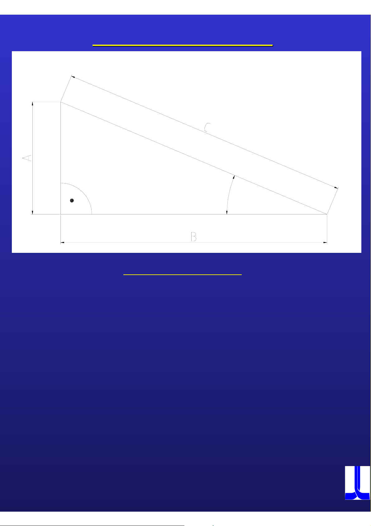
Variables Function:
In OSP controller it is possible to use 5 kind of Variable.
1.)Common variables
2.)Local variables
Common Variables
The term ”common” in ”common variables” can be literally understood as common; they can be used in
common for main and subprograms. When the same variable is used in two or more programs, the
variable number used in those programs must be identical. Therefore, a common variable, the result of
calculation in one program, can be referred to in other programs.
[Format]
V numerals = numerical data or expression
Common variable designations consist of up to three digits following ”V”. The usable common variables
are V1 through 200.
Examples:
N101 V5 = 10
N101 V5 = V5 + 1
[Details]
- Common variables are effective both in main programs and subprograms.
- Common variables are not affected by resetting the control or turning power off. That is, the
data are retained unless they are re-set or a control software is installed.
- Besides setting or changing them in a program, common variables can be set or changed by
setting a parameter. For detailed information on parameter setting, refer to SECTION
PARAMETER SETTING, DATA OPERATION in OPERATION MANUAL.
Local Variables
As is apparent from the term ”local”, local variables are the variables that a user can set as desired with
meaningful names assigned to them. Up to 127 local variables each can be used for the A and B saddles.
[Format]
Letter Letter two alphanumeric = Numerical data or expression
O, N and V cannot be used.
Example: ‘DlA1’ ‘ITH5’
54
OKUMA

[Details]
A local variable cannot be assigned the same name as already used for a
function name, comparison operator, Boolean operator, or extended address
character.
Extended address characters are provided to realise LAP, pattern processing,
and user-specific fixed cycles. They are necessary because there are not
enough letters in the alphabet to cover the required number of extension
names. The following extended address characters are currently used.
<AA> <AB> <DA> <DB> <FA> <FB> <IA> <IB> <KA> <KB>
<LA> <LB> <RA> <RB> <SA> <SB> <TA> <TB> <UA> <UB>
<WA> <WB> <XA> <XB> <ZA> <ZB> <BC> <BR>
Characteristics of Local Variables
- Local variables are cleared when the control is reset.
- When a new local variable is set in a main program, that is, when data is
assigned to a new local variable name, that local variable name and
corresponding data are registered in the memory.
NOTICE
If a local variable name is used without
- When new data is assigned to a local variable already registered with other
data, that old data is updated.
N0010 DIA1 = 160
In N0010, numerical data "160" is assigned to local variable
:
name "DIA1", and this data remains effective up to sequence
:
:
N0049. In N0050, the new numerical data "200" is assigned
to the same local variable name "DlA1". This clears the old
setting any data for it, an alarm results.
N0049
data "160" and replaces it with the new data "200"
N0050 DIA1 = 20
:
:
:
- Up to 127 local variables can be used.
55
OKUMA

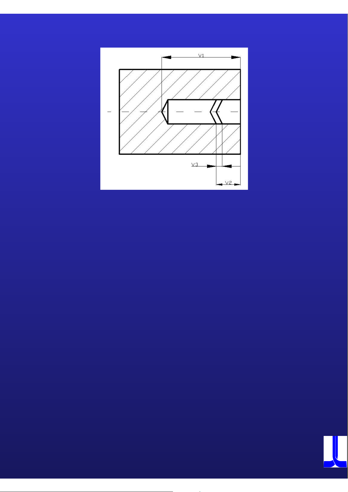
Lesson with common variable
Lesson with common variable
Program construction with common variable
V1=40
V2=20
V3=60
V4=50
V5=100
V6=80
V7=140
V8=110
V9=160
G50 S4500
G00 X500 Z500
G00 X=V9 Z2 T0101 G96 S250 M03 M08
G01 X0 Z0
X=V1
Z=-V2
X=V3
Z=-V4
X=V5 Z=-V6
X=V7
Z=-V8
X=V9
G00 X500 Z500 M09
M02
56
OKUMA

DIA1=40
LEN2=20
DIA3=60
Lesson with local variable
Lesson with local variable
Program construction with local variable
LEN4=50
DIA5=100
LEN6=80
DIA7=140
LEN8=110
DIA9=160
G50 S4500
G00 X500 Z500
G00 X=DIA9 Z2 T0101 G96 S250 M03 M08
G01 X0 Z0
X=DIA1
Z=-LEN2
X=DIA3
Z=-LEN4
X=DIA5 Z=-LEN6
X=DIA7
Z=-LEN8
X=DIA9
G00 X500 Z500 M09
M02
67
OKUMA

Arithmetic Operation Function
This function allows arithmetic operation using variables. The programming can be
done in the same way as for general arithmetic expressions.
Address character, Extended address character, Variable = Expression
The expression on the right-hand side, requesting an arithmetic operation, is made
up of constants, variables, comparison expressions, and operators.
The arithmetic and comparison expressions are described below.
1. )Arithmetic Expression
2.) Comparison Expression
58
OKUMA

3. ) Function
V1= V1 * SIN [V3]
V1= V1 * COS [V3]
V1= V1 * TAN [V3]
V1 = ATAN [V2]
V1 = ATAN2 [2]
V1 = SQRT [V2]
V1 = ABS [V2]
V1 = BIN [V2]
V1 = BCD [V2]
V1 = ROUND [V2]
V1 = FIX [V2]
V1 = FUP [V2]
V1 = DROUND [V2]
V1 = DFIX [V2]
V1 = DFUP [V2]
V1 = MOD [V2/V3]
59
OKUMA

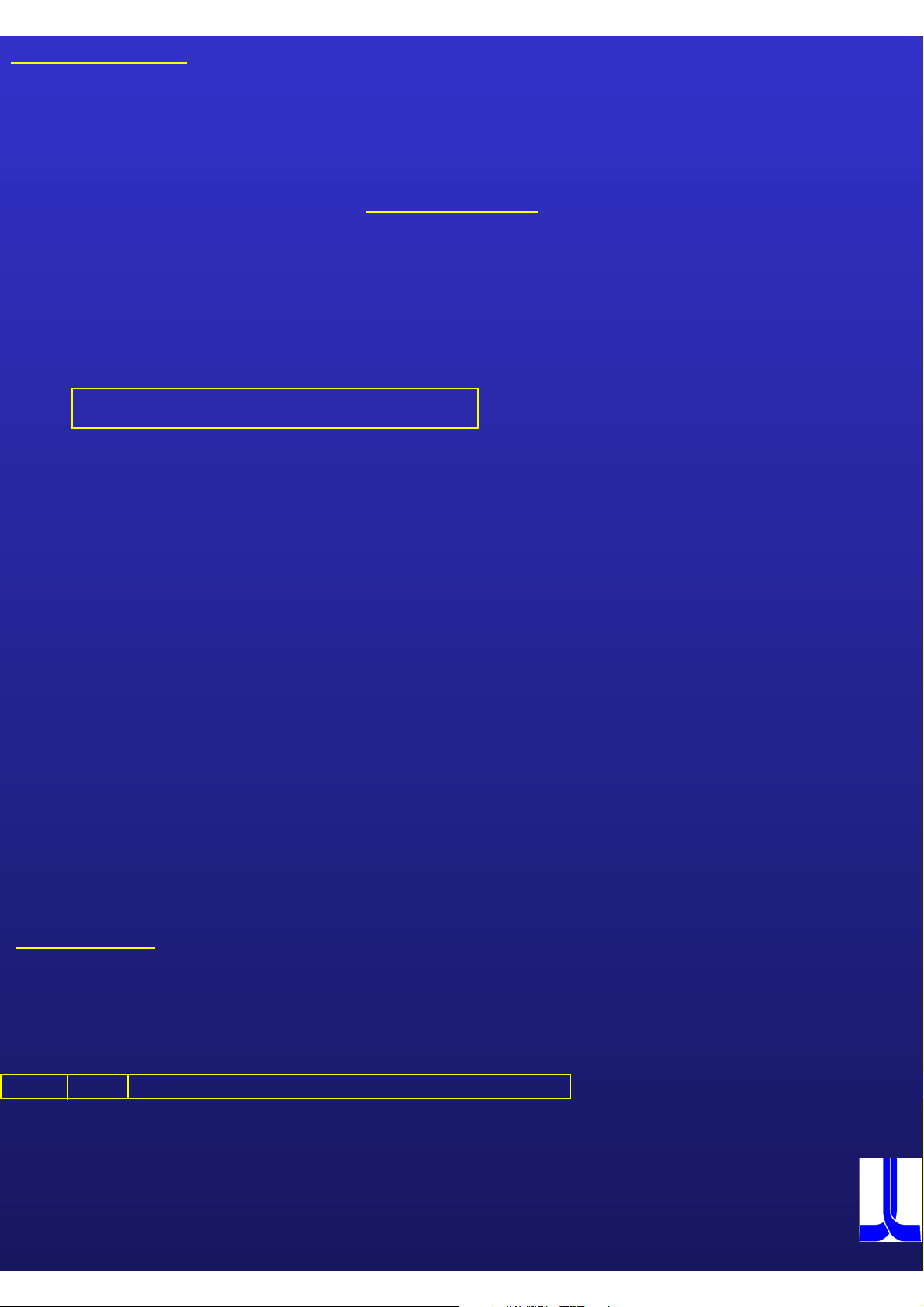
Lesson for triangle calculation
Lesson for triangle calculation
Formula for calculate the sides of a triangle: A² + B²=C² ( Pythagorean )
A = 25
B = 55
C = ?
One possibility for calculation.
V1=25
V2=55
V10=V1*V1 (625)
V11=V2*V2 (3025)
V12=V10+V11 (3650)
V13=SQRT[V12] (60.415)
M2
Another possibility for calculation
V1=25
V2=55
V3=SQRT[[V1*V1]+[ V2*V2]]
M2
A maximum of seven pairs of [ ] can used.
60
OKUMA
Lesson for triangle calculation
Lesson for triangle calculation
D
Tan D = ----- Sin D = ----- Cos D = -----
A = 25
B = 55
C = 60.415
D = ?
V1=25
V2=55
V3=60.415
Formula for angle calculation:
AAB
BCC
V10=V1/V2 ( 0.454545)
V11=ATAN[V10] (24.444°)
M2
61
OKUMA

Exercise for triangle calculation
Exercise for triangle calculation
E
D
Exercise:
Please calculate
Side A and B and angle E
We have:
C = 75.716
D = 32.335
Solution:
62
OKUMA

Practical Exercise
Practical Exercise
Please make a macro for the workpiece shape above.
63
OKUMA

Example for make an counter program with alarm
Example for make an counter program with alarm
message
message
V1=0
V2=20
N10
N20
.
.
.
.
.
.
N90
N100
V1=V1+1
IF[V1 GE V2] NALM
GOTO N10
NALM VUACM[1]='COUNTER OVER'
VDOUT[992]=4711
M2
Alarm message programming
VUACM[1] = 'COUNTER OVER'
System Variable Alarm message max. 16 characters
VDOUT [ 992 ] =
System Variable
4711
Alarm A,B or C
Alarm number designing by operator
64
OKUMA

Test
Test
Please make a macro for the deep hole drilling, after every step, drill should retract
at the Z - position where the macro starts.
V1=50 ( Z – endpoint of hole )
V2=5 ( Depth of cut per peck feed )
V3=0.5 ( Approaching distance )
OKUMA
 Loading...