


CNC SYSTEM
OSP-P200L/P20L OSP-P200L-R/P20L-R
PROGRAMMING MANUAL
(3rd Edition)
Pub No. 5238-E-R2 (LE33-013-R3) Aug. 2007

5238-E P-(i)
SAFETY PRECAUTIONS
SAFETY PRECAUTIONS
The machine is equipped with safety devices which serve to protect personnel and the machine itself from hazards arising from unforeseen accidents. However, operators must not rely exclusively on these safety devices: they must also become fully familiar with the safety guidelines presented below to ensure accidentfree operation.
This instruction manual and the warning signs attached to the machine cover only those hazards which Okuma can predict. Be aware that they do not cover all possible hazards.
1.Precautions Relating to Installation
(1)Please be noted about a primary power supply as follows.
•Do not draw the primary power supply from a distribution panel that also supplies a major noise source (for example, an electric welder or electric discharge machine) since this could cause malfunction of the CNC unit.
•If possible, connect the machine to a ground not used by any other equipment. If there is no choice but to use a common ground, the other equipment must not generate a large amount of noise (such as an electric welder or electric discharge machine).
(2)Installation Environment
Observe the following points when installing the control enclosure.
•Make sure that the CNC unit will not be subject to direct sunlight.
•Make sure that the control enclosure will not be splashed with chips, water, or oil.
•Make sure that the control enclosure and operation panel are not subject to excessive vibrations or shock.
•The permissible ambient temperature range for the control enclosure is 5 to 40°C.
•The permissible ambient humidity range for the control enclosure is relative humidity 50% or less at 40°C (no condensation).
•The maximum altitude at which the control enclosure can be used is 1000 m (3281ft.).
2.Points to Check before Turning on the Power
(1)Close all the doors of the control enclosure and operation panel to prevent the entry of water, chips, and dust.
(2)Make absolutely sure that there is nobody near the moving parts of the machine, and that there are no obstacles around the machine, before starting machine operation.
(3)When turning on the power, turn on the main power disconnect switch first, then the CONTROL ON switch on the operation panel.

5238-E P-(ii)
SAFETY PRECAUTIONS
3.Precautions Relating to Manual/Continuous Operation
(1)Follow the instruction manual during operation.
(2)Do not operate the machine with the front cover, chuck cover, or another protective cover removed.
(3)Close the front cover before starting the machine.
(4)When machining the initial workpiece, check for machine operations, run the machine under no load to check for interference among components, cut the workpiece in the single block mode, and then start continuous operation.
(5)Ensure your safety before rotating the spindle or moving a machine part.
(6)Do not touch chips or workpiece while the spindle is rotating.
(7)Do not stop a rotating part with hand or another means.
(8)Check that the condition of hydraulic chuck jaws as mounted, operating pressure, and maximum permissible revolving speed.
(9)Check the condition and location of the cutting tool as mounted.
(10)Check the tool offset value.
(11)Check the zero offset value.
(12)Check that the SPINDLE OVERRIDE and FEEDRATE OVERRIDE dials on the NC operation panel are set to 100%.
(13)When moving the turret, check the software limits for X- and Z-axes or the locations of limit switch dogs to prevent interference with the chuck and tailstock.
(14)Check the location of the turret.
(15)Check the location of the tailstock.
(16)Cut workpieces with a transmitted power and torque within the permissible range.
(17)Chuck each workpiece firmly.
(18)Check that the coolant nozzle is properly located.
4.On Finishing Work
(1)On finishing work, clean the vicinity of the machine.
(2)Return the ATC, APC and other equipment to the predetermined retraction position.
(3)Always turn off the power to the machine before leaving it.
(4)To turn off the power, turn off the CONTROL ON switch on the operation panel first, then the main power disconnect switch.

5238-E P-(iii)
SAFETY PRECAUTIONS
5.Precautions during Maintenance Inspection and When Trouble Occurs
In order to prevent unforeseen accidents, damage to the machine, etc., it is essential to observe the following points when performing maitenance inspections or during checking when trouble has occurred.
(1)When trouble occurs, press the emergency stop button on the operation panel to stop the machine.
(2)Consult the person responsible for maintenance to determine what corrective measures need to be taken.
(3)If two or more persons must work together, establish signals so that they can communicate to confirm safety before proceeding to each new step.
(4)Use only the specified replacement parts and fuses.
(5)Always turn the power off before starting inspection or changing parts.
(6)When parts are removed during inspection or repair work, always replace them as they were and secure them properly with their screws, etc.
(7)When carrying out inspections in which measuring instruments are used - for example voltage checks - make sure the instrument is properly calibrated.
(8)Do not keep combustible materials or metals inside the control enclosure or terminal box.
(9)Check that cables and wires are free of damage: damaged cables and wires will cause current leakage and electric shocks.
(10)Maintenance inside the Control Enclosure
a.Switch the main power disconnect switch OFF before opening the control enclosure door.
b.Even when the main power disconnect switch is OFF, there may some residual charge in the MCS drive unit (servo/spindle), and for this reason only service personnel are permitted to perform any work on this unit. Even then, they must observe the following precautions.
•MCS drive unit (servo/spindle)
The residual voltage discharges two minutes after the main switch is turned OFF.
c.The control enclosure contains the NC unit, and the NC unit has a printed circuit board whose memory stores the machining programs, parameters, etc. In order to ensure that the contents of this memory will be retained even when the power is switched off, the memory is supplied with power by a battery. Depending on how the printed circuit boards are handled, the contents of the memory may be destroyed and for this reason only service personnel should handle these boards.

5238-E P-(iv)
SAFETY PRECAUTIONS
(11)Periodic Inspection of the Control Enclosure
a.Cleaning the cooling unit
The cooling unit in the door of the control enclosure serves to prevent excessive temperature rise inside the control enclosure and increase the reliability of the NC unit. Inspect the following points every three months.
•Is the fan motor inside the cooling unit working?
The motor is normal if there is a strong draft from the unit.
•Is the external air inlet blocked?
If it is blocked, clean it with compressed air.
6.General Precautions
(1)Keep the vicinity of the machine clean and tidy.
(2)Wear appropriate clothing while working, and follow the instructions of someone with sufficient training.
(3)Make sure that your clothes and hair cannot become entangled in the machine. Machine operators must wear safety equipment such as safety shoes and goggles.
(4)Machine operators must read the instruction manual carefully and make sure of the correct procedure before operating the machine.
(5)Memorize the position of the emergency stop button so that you can press it immediately at any time and from any position.
(6)Do not access the inside of the control panel, transformer, motor, etc., since they contain highvoltage terminals and other components which are extremely dangerous.
(7)If two or more persons must work together, establish signals so that they can communicate to confirm safety before proceeding to each new step.

5238-E P-(v)
SAFETY PRECAUTIONS
7.Symbols Used in This Manual
The following warning indications are used in this manual to draw attention to information of particular importance. Read the instructions marked with these symbols carefully and follow them.

 DANGER
indicates an imminently hazardous situation which, if not avoided, will result in death or serious injury.

 WARNING
indicates a potentially hazardous situation which, if not avoided, could result in death or serious injury.

 CAUTION
indicates a potentially hazardous situation which, if not avoided, may result in minor or moderate injury.

 CAUTION
indicates a potentially hazardous situation which, if not avoided, may result in damage to your property.
SAFETYINSTRUCTIONS
indicates general instructions for safe operation.

5238-E P-(i)
INTRODUCTION
INTRODUCTION
Thank you very much for purchasing our numerical control unit.
Before using this NC unit (hereafter simply called NC), thoroughly read this programming manual (hereafter called this manual) in order to ensure correct use.
This manual explains how to use and maintain the NC so that it will deliver its full performance and maintain accuracy over a long term.
You must pay particular attention to the cautions given in this manual, read them carefully, and make sure you fully understand them before operating the NC.
Display Screens
The NC display screens vary with the selected NC specifications.
The screens shown in this manual, therefore, may not exactly the same with those displayed on your NC.

|
|
5238-E P-(i) |
|
|
TABLE OF CONTENTS |
|
TABLE OF CONTENTS |
|
SECTION 1 PROGRAM CONFIGURATIONS ............................................................. |
1 |
|
1. |
Program Types ........................................................................................................................ |
1 |
2. |
Program Name ........................................................................................................................ |
2 |
3. |
Sequence Name ...................................................................................................................... |
3 |
4. |
Program Format....................................................................................................................... |
4 |
|
4-1. Word Configuration........................................................................................................... |
4 |
|
4-2. Block Configuration .......................................................................................................... |
4 |
|
4-3. Program............................................................................................................................ |
4 |
|
4-4. Programmable Range of Address Characters.................................................................. |
5 |
5. |
Mathematical Operation Functions .......................................................................................... |
6 |
6. |
Block Delete............................................................................................................................. |
8 |
7. |
Comment Function (CONTROL OUT/IN) ................................................................................ |
8 |
8. |
Program Storage Memory Capacity ........................................................................................ |
9 |
9. |
Variable Limits ......................................................................................................................... |
9 |
10.Determining Feedrate for Cutting along C-Axis ..................................................................... |
10 |
|
|
10-1.Cutting by Controlling the C-axis Only........................................................................... |
10 |
|
10-2.Cutting by Controlling Both C-axis and Z-axis Simultaneously ..................................... |
11 |
|
10-3.Cutting by Controlling Both C-axis and X-axis Simultaneously ..................................... |
12 |
|
10-4.Cutting by Simultaneous 3-axis Control of X-, Z-, and C-axis ....................................... |
14 |
SECTION 2 COORDINATE SYSTEMS AND COMMANDS ...................................... |
16 |
|
1. |
Coordinate Systems .............................................................................................................. |
16 |
|
1-1. Coordinate Systems and Values .................................................................................... |
16 |
|
1-2. Encoder Coordinate System........................................................................................... |
16 |
|
1-3. Machine Coordinate System .......................................................................................... |
16 |
|
1-4. Program Coordinate System .......................................................................................... |
16 |
2. |
Coordinate Commands.......................................................................................................... |
18 |
|
2-1. Controlled Axis ............................................................................................................... |
18 |
|
2-2. Commands in Inch System............................................................................................. |
20 |
|
2-3. Position of Decimal Point................................................................................................ |
20 |
|
2-4. Absolute and Incremental Commands (G90, G91) ........................................................ |
22 |
|
2-5. Diametric and Radial Commands................................................................................... |
23 |
SECTION 3 MATH FUNCTIONS ............................................................................... |
24 |
|
1. |
Positioning (G00) ................................................................................................................... |
24 |
2. |
Linear Interpolation (G01)...................................................................................................... |
24 |
3. |
Circular Interpolation (G02, G03)........................................................................................... |
26 |
4. |
Automatic Chamfering ........................................................................................................... |
30 |
|
4-1. C-chamfering (G75)........................................................................................................ |
30 |
|
4-2. Rounding (G76) .............................................................................................................. |
32 |

|
|
5238-E P-(ii) |
|
TABLE OF CONTENTS |
|
|
4-3. Automatic Any-Angle Chamfering .................................................................................. |
34 |
5. |
Torque Limit and Torque Skip Function................................................................................. |
36 |
|
5-1. Torque Limit Command (G29)........................................................................................ |
36 |
|
5-2. Torque Limit Cancel Command (G28)............................................................................ |
36 |
|
5-3. Torque Skip Command (G22) ........................................................................................ |
37 |
|
5-4. Parameter Setting........................................................................................................... |
38 |
|
5-5. Program Example........................................................................................................... |
39 |
SECTION 4 PREPARATORY FUNCTIONS............................................................... |
40 |
|
1. |
Dwell (G04)............................................................................................................................ |
40 |
2. |
Zero Shift/Max. Spindle Speed Set (G50) ............................................................................. |
41 |
|
2-1. Zero Shift ........................................................................................................................ |
41 |
|
2-2. Max. Spindle Speed Set ................................................................................................. |
42 |
3. |
Droop Control (G64, G65) ..................................................................................................... |
42 |
4. |
Feed Per Revolution (G95).................................................................................................... |
43 |
5. |
Feed Per Minute (G94) .......................................................................................................... |
43 |
6. |
Constant Speed Control (G96/G97) ...................................................................................... |
44 |
SECTION 5 S, T, AND M FUNCTIONS ..................................................................... |
45 |
|
1. |
S Functions (Spindle Functions)............................................................................................ |
45 |
2. |
SB Code Function.................................................................................................................. |
45 |
3. |
T Functions (Tool Functions) ................................................................................................. |
46 |
4. |
M Functions (Auxiliary Functions).......................................................................................... |
47 |
5. |
M-tool Spindle Commands .................................................................................................... |
51 |
|
5-1. Programming Format...................................................................................................... |
51 |
|
5-2. M Codes Used for C-axis Operation............................................................................... |
52 |
6. |
STM Time Over Check Function ........................................................................................... |
54 |
|
6-1. Check ON Conditions ..................................................................................................... |
54 |
|
6-2. S, T, M Cycle Time Setting............................................................................................. |
54 |
|
6-3. Timing Chart Example .................................................................................................... |
55 |
SECTION 6 OFFSET FUNCTION ............................................................................. |
56 |
|
1. |
Tool Nose Radius Compensation Function (G40, G41, G42) ............................................... |
56 |
|
1-1. General Description........................................................................................................ |
56 |
|
1-2. Tool Nose Radius Compensation for Turning Operations.............................................. |
56 |
|
1-3. Compensation Operation................................................................................................ |
57 |
|
1-4. Nose Radius Compensation Commands (G, T Codes).................................................. |
59 |
|
1-5. Data Display ................................................................................................................... |
60 |
|
1-6. Buffer Operation ............................................................................................................. |
61 |
|
1-7. Path of Tool Nose "R" Center in Tool Nose Radius Compensation Mode ..................... |
61 |
|
1-8. Tool Nose Radius Compensation Programming ............................................................ |
62 |
2. |
Cutter Radius Compensation Function.................................................................................. |
90 |

|
|
5238-E P-(iii) |
|
TABLE OF CONTENTS |
|
|
2-1. Overview......................................................................................................................... |
90 |
|
2-2. Programming .................................................................................................................. |
90 |
|
2-3. Operations ...................................................................................................................... |
92 |
SECTION 7 FIXED CYCLES ..................................................................................... |
96 |
|
1. |
Fixed Cycle Functions ........................................................................................................... |
96 |
2. |
Fixed Thread Cutting Cycles ................................................................................................. |
97 |
|
2-1. Fixed Thread Cutting Cycle: Longitudinal (G31, G33).................................................... |
97 |
|
2-2. Fixed Thread Cutting Cycle: End Face (G32) ................................................................ |
99 |
3. |
Non-Fixed Thread Cutting Cycle (G34, G35) ...................................................................... |
102 |
4. |
Precautions when Programming Thread Cutting Cycles ..................................................... |
103 |
5. |
Thread Cutting Compound Cycle (G71/G72) ...................................................................... |
109 |
|
5-1. Longitudinal Thread Cutting Cycle (G71) ..................................................................... |
109 |
|
5-2. Program Example for Longitudinal Thread Cutting Compound Fixed Cycle |
|
|
(G71) ............................................................................................................................ |
110 |
|
5-3. Transverse Thread Cutting Compound Fixed Cycle (G72) .......................................... |
111 |
|
5-4. M Code Specifying Thread Cutting Mode and Infeed Pattern ...................................... |
112 |
|
5-5. Multi-thread Thread Cutting Function in Compound Fixed Thread Cutting Cy- |
|
|
cle ................................................................................................................................. |
125 |
6. |
Grooving/Drilling Compound Fixed Cycle............................................................................ |
126 |
|
6-1. Longitudinal Grooving Fixed Cycle (G73)..................................................................... |
126 |
|
6-2. Example Program for Longitudinal Grooving Compound Fixed Cycle (G73) ............... |
127 |
|
6-3. Transverse Grooving/Drilling Fixed Cycle (G74) .......................................................... |
128 |
|
6-4. Example Program for Transverse Grooving/Drilling Fixed Cycle (G74) ....................... |
129 |
|
6-5. Axis Movements in Grooving/Drilling Compound Fixed Cycle...................................... |
129 |
7. Tapping Compound Fixed Cycle ......................................................................................... |
130 |
|
|
7-1. Right-hand Tapping Cycle (G77).................................................................................. |
130 |
|
7-2. Left-hand Tapping Cycle (G78) .................................................................................... |
131 |
8. Compound Fixed Cycles...................................................................................................... |
132 |
|
|
8-1. List of Compound Fixed Cycle Commands .................................................................. |
132 |
|
8-2. Basic Axis Motions ....................................................................................................... |
133 |
|
8-3. Address Characters...................................................................................................... |
139 |
|
8-4. M Codes ....................................................................................................................... |
139 |
|
8-5. Drilling Cycle (G181) .................................................................................................... |
140 |
|
8-6. Boring Cycle (G182) ..................................................................................................... |
141 |
|
8-7. Deep Hole Drilling Cycle (G183) .................................................................................. |
142 |
|
8-8. Tapping Cycle (G184) .................................................................................................. |
144 |
|
8-9. Longitudinal Thread Cutting Cycle (G185) ................................................................... |
145 |
|
8-10.Transverse Thread Cutting Cycle (G186).................................................................... |
146 |
|
8-11.Longitudinal Straight Thread Cutting (G187)............................................................... |
147 |
|
8-12.Transverse Straight Thread Cutting (G188) ................................................................ |
148 |
|
8-13.Reaming/Boring Cycle (G189)..................................................................................... |
149 |
|
8-14.Key Way Cutting (G190).............................................................................................. |
150 |
|
8-15.Synchronized Tapping Cycle....................................................................................... |
153 |
|
|
5238-E P-(iv) |
|
TABLE OF CONTENTS |
|
|
8-16.Repeat Function .......................................................................................................... |
156 |
|
8-17.Tool Relieving Command in Deep-hole Drilling Cycle for Chip Discharge. ................. |
156 |
|
8-18.Drilling Depth Setting (Only for drilling cycles) ............................................................ |
157 |
|
8-19.Selection of Return Point............................................................................................. |
160 |
|
8-20.M-tool spindle Interlock Release Function (optional)................................................... |
161 |
|
8-21.Other Remarks ............................................................................................................ |
161 |
|
8-22.Program Examples ...................................................................................................... |
162 |
SECTION 8 LATHE AUTO-PROGRAMMING FUNCTION (LAP)............................ |
167 |
|
1. |
Overview.............................................................................................................................. |
167 |
2. |
G Codes Used to Designate Cutting Mode (G80, G81, G82, G83) ..................................... |
168 |
3. |
List of Cutting Modes ........................................................................................................... |
169 |
4. |
Code and Parameter Lists ................................................................................................... |
174 |
5. |
Bar Turning Cycle (G85)...................................................................................................... |
176 |
6. |
Change of Cutting Conditions in Bar Turning Cycle (G84) .................................................. |
177 |
7. |
Copy Turning Cycle (G86) ................................................................................................... |
178 |
8. |
Finish Turning Cycle (G87).................................................................................................. |
179 |
9. |
Continuous Thread Cutting Cycle (G88).............................................................................. |
180 |
10.AP Modes ............................................................................................................................ |
181 |
|
|
10-1.AP Mode I (Bar Turning).............................................................................................. |
181 |
|
10-2.AP Mode II (Copy Turning).......................................................................................... |
190 |
|
10-3.AP Mode III (Continuous Thread Cutting Cycle) ......................................................... |
196 |
|
10-4.AP Mode IV (High-speed Bar Turning Cycle).............................................................. |
197 |
|
10-5.AP Mode V (Bar Copying Cycle) ................................................................................. |
214 |
11.Application of LAP Function................................................................................................. |
232 |
|
SECTION 9 CONTOUR GENERATION .................................................................. |
235 |
|
1. |
Contour Generation Programming Function (Face) ............................................................ |
235 |
|
1-1. Function Overview........................................................................................................ |
235 |
|
1-2. Programming Format.................................................................................................... |
235 |
|
1-3. Programming Examples ............................................................................................... |
236 |
|
1-4. Supplementary Information .......................................................................................... |
244 |
2. |
Contour Generation Programming Function (Side) ............................................................. |
247 |
|
2-1. Overview....................................................................................................................... |
247 |
|
2-2. Programming Format.................................................................................................... |
248 |
|
2-3. Cautions ....................................................................................................................... |
248 |
SECTION 10COORDINATE SYSTEM CONVERSION............................................ |
251 |
|
1. |
Function Overview ............................................................................................................... |
251 |
2. |
Conversion Format .............................................................................................................. |
252 |
3. |
Program Examples .............................................................................................................. |
252 |
4. |
Supplementary Information.................................................................................................. |
254 |

|
|
5238-E P-(v) |
|
TABLE OF CONTENTS |
|
SECTION 11PROGRAMMING FOR SIMULTANEOUS 4-AXIS CUTS (2S |
|
|
|
Model) .................................................................................................. |
255 |
1. |
Programming ....................................................................................................................... |
255 |
|
1-1. Turret Selection ............................................................................................................ |
255 |
|
1-2. Synchronization Command (P Code) ........................................................................... |
256 |
|
1-3. Waiting Synchronization M Code (M100) for Simultaneous Cuts................................. |
257 |
2. |
Programming Format........................................................................................................... |
258 |
3. |
Precautions on Programming Simultaneous 4-axis Cuts .................................................... |
260 |
4. |
Programming Example ........................................................................................................ |
262 |
|
4-1. Program Process Sheet ............................................................................................... |
264 |
SECTION 12USER TASK ........................................................................................ |
265 |
|
1. |
Overview.............................................................................................................................. |
265 |
2. |
Types of User Task Function............................................................................................... |
266 |
|
2-1. Relationship Between Types of Program Files and User Task Functions.................... |
266 |
|
2-2. Comparison of User Task 1 and User Task 2 .............................................................. |
266 |
|
2-3. Fundamental Functions of User Task........................................................................... |
268 |
3. |
User Task 1 ......................................................................................................................... |
269 |
|
3-1. Control Statement Function 1....................................................................................... |
269 |
|
3-2. Variables....................................................................................................................... |
272 |
|
3-3. Arithmetic Operation Function 1 ................................................................................... |
286 |
4. |
User Task 2 ......................................................................................................................... |
287 |
|
4-1. Control Functions 2 ...................................................................................................... |
287 |
|
4-2. I/O Variables................................................................................................................. |
297 |
|
4-3. Arithmetic Operation Function 2 ................................................................................... |
298 |
5. |
Supplemental Information on User Task Programs............................................................. |
301 |
|
5-1. Sequence Return in Program Using User Task ........................................................... |
301 |
|
5-2. Data Types, Constants ................................................................................................. |
301 |
|
5-3. Types/Operation Rules of Variables and Evaluation of Their Values........................... |
302 |
6. |
Examples of User Task Programs ....................................................................................... |
305 |
SECTION 13SCHEDULE PROGRAMS ................................................................... |
315 |
|
1. |
Overview.............................................................................................................................. |
315 |
2. |
PSELECT Block................................................................................................................... |
316 |
3. |
Branch Block........................................................................................................................ |
318 |
4. |
Variables Setting Block........................................................................................................ |
318 |
5. |
Schedule Program End Block.............................................................................................. |
319 |
6. |
Program Example ................................................................................................................ |
319 |
SECTION 14OTHER FUNCTIONS .......................................................................... |
321 |
|
1. |
Direct Taper Angle Command ............................................................................................. |
321 |
2. |
Barrier Check Function ........................................................................................................ |
323 |
|
|
|
5238-E P-(vi) |
|
|
|
TABLE OF CONTENTS |
|
2-1. General Description...................................................................................................... |
323 |
|
|
2-2. |
Chuck Barrier and Tailstock Barrier.............................................................................. |
323 |
3. |
Operation Time Reduction Function .................................................................................... |
326 |
|
4. |
Turret Unclamp Command (for NC Turret Specification)..................................................... |
326 |
|
5. |
SPINDLE SPEED VARIATION CONTROL FUNCTION...................................................... |
327 |
|
|
5-1. |
Outline .......................................................................................................................... |
327 |
|
5-2. |
Method of Spindle Speed Variation Control ................................................................. |
327 |
|
5-3. |
Control Specifications................................................................................................... |
327 |
|
5-4. Programming Example ................................................................................................. |
330 |
|
SECTION 15APPENDIX .......................................................................................... |
331 |
|
1. |
G Code Table ...................................................................................................................... |
331 |
2. |
Table of Mnemonic Codes................................................................................................... |
337 |
3. |
Table of System Variables................................................................................................... |
345 |

5238-E P-1
SECTION 1 PROGRAM CONFIGURATIONS
SECTION 1 PROGRAM CONFIGURATIONS
1.Program Types
For OSP-P200L, three kinds of programs are used: schedule programs, main programs, and subprograms. The following briefly explains these three kinds of programs.
Schedule Program
When more than one type of workpiece is machined in continuous operation using a bar feeder or other equipment, multiple main programs are used. A schedule program is used to specify the order in which the main programs are executed and the number of times the individual main program is executed. Using a schedule program makes it possible to carry out untended operation easily.
It is not necessary to assign a program name. The END code must be specified at the end of a schedule program. For details, refer to SECTION 14, "SCHEDULE PROGRAMS".
Main Program
A main program contains a series of commands to machine one type of workpiece. Subprograms can be called from a main program to simplify programming.
A main program begins with a program name which begins with address character "O" and ends with M02 or M30.
Subprogram
A subprogram can be called from a main program or another subprogram. There are two types of subprograms: those written and supplied by Okuma (maker subprogram), and those written by the customer (user subprogram).
The program name, which must start with "O", is required at the beginning of the subprogram. The RTS command must be specified at the end of the subprogram. For details, refer to SECTION 13, USER TASK.
•Program file format
Main file name: Max. 16 alphanumeric characters starting with an alphabet Extension: Max. 3 alphabetic characters
•••.
Main file name Extension
LE33013R0300300010001
• Extensions
SDF : Schedule program file MIN : Main program file
SSB : System subprogram file SUB : User subprogram file

5238-E P-2
SECTION 1 PROGRAM CONFIGURATIONS
2.Program Name
With the OSP-P200L, programs are called and executed by designating the program name or program number assigned to the beginning of individual programs. This simplifies programs.
A program name that contains only numbers is called a program number.
Program Name Designation
•Enter letters of the alphabet (A to Z) or numbers (0 to 9) following address character "O". Note that no space is allowed between "O" and a letter of the alphabet or a number. Similarly, no space is allowed between letters of the alphabet and numbers.
•Up to four characters can be used.
•An alphabetic character can only be used in a program name if it begins with an alphabetic character. Although a program beginning with an alphabetic character can contain a number in it, one that begins with a number cannot contain an alphabetic character.
•A block which contains a program name must not contain other commands.
•A program name may not be used for a schedule program.
•The program name assigned to a subprogram must begin with address character "O", but this is not mandatory for main programs.
•Since program names are handled in units of characters, the following names are judged to be different program names.
•O0123 and O123
•O00 and O0
•Do not assign the same name to more than one program, otherwise it will not be possible to select the intended program.

5238-E P-3
SECTION 1 PROGRAM CONFIGURATIONS
3.Sequence Name
All blocks in a program are assigned a sequence name that begins with address character "N" followed by an alphanumeric sequence.
Functions such as a sequence search function, a sequence stop function and a branching function can be used for blocks assigned a sequence name.
A sequence name that contains only numbers is called a sequence number.
Sequence Name Designation
•Enter letters of the alphabet (A to Z) or numbers (0 to 9) following address character "N".
•Up to four characters can be used.
•Both alphabetic characters and numbers may be used in a sequence name. If an alphabetic character is used in a sequence name, however, the sequence name must begin with an alphabetic character.
•A sequence name must be placed at the top of block. However, a block delete command may be placed preceding a sequence name.
•Sequence numbers may be specified in any order. They can be used however desired, provided there is no duplication of numbers.
•Since sequence names are handled in units of characters, the following names are judged to be different sequence names.
•N0123 and N123
•N00 and N0
•When a sequence name is used, place a space or a tab after the sequence name.

5238-E P-4
SECTION 1 PROGRAM CONFIGURATIONS
4.Program Format
4-1. Word Configuration
A word is defined as an address character followed by a group of numeric values, an expression, or a variable name. If a word consists of an expression or a variable, the address character must be followed by an equal sign "=".
Examples:
|
X-100 |
|
Z=100 SIN[50] |
|
Z=V1+V2 |
||||||
|
|
|
|
|
|
|
|
|
|
|
|
Address Numerical |
Address Formula |
Address Variable |
|||||||||
|
value |
|
|
|
|
|
|
|
|
|
|
|
|
|
|
|
|
|
|
|
|
|
|
|
Word |
|
|
|
Word |
|
|
Word |
|||
LE33013R0300300040001
•An address character is one of the alphabetic characters A through Z and defines the meaning of the entry specified following it. In addition, an extended address character, consisting of two alphabetic characters, may also be used.
•Refer to SECTION 13, 3-2. "Variables" for more information on variables.
4-2. Block Configuration
A group consisting of several words is called a block, and a block expresses a command. Blocks are delimited by an end of block code.
•The end of block code differs depending on the selected code system, lSO or EIA: ISO: "LF"
ElA: "CR"
•A block may contain up to 158 characters.
4-3. Program
A program consists of several blocks.

5238-E P-5
SECTION 1 PROGRAM CONFIGURATIONS
4-4. Programmable Range of Address Characters
Address |
Function |
Programmable Range |
Remarks |
||
Metric |
Inch |
||||
|
|
|
|||
O |
Program name |
0000 to 9999 |
same as left |
Alphabetic |
|
N |
Sequence name |
0000 to 9999 |
same as left |
characters available |
|
|
|
|
|
|
|
G |
Preparatory function |
0 to 999 |
same as left |
|
|
|
|
|
|
|
|
X, Z |
Coordinate values |
±99999.999 mm |
±9999.9999 inch |
|
|
(linear axis) |
|
||||
|
|
|
|
||
|
|
|
|
|
|
C |
Coordinate values |
±359.999 deg. |
±359.999 deg. |
|
|
(rotary axis) |
|
||||
|
|
|
|
||
|
|
|
|
|
|
|
Coordinate values of |
|
|
|
|
|
center of arc |
|
|
|
|
|
Taper amount and |
±99999.999 mm |
±9999.9999 inch |
|
|
I, K |
depth of cut in fixed |
|
|||
|
thread cutting cycle |
|
|
|
|
|
Shift amount in |
|
|
|
|
|
grooving cycle |
|
|
|
|
|
|
|
|
|
|
D, U, W, H, L |
Automatic |
0 to 99999.999 mm |
0 to 9999.9999 inch |
|
|
E |
programming |
±99999.999 mm/rev |
±9999.9999 inch/rev |
|
|
|
commands |
|
|
|
|
A, B |
0 to 99999.999 deg. |
0 to 9999.9999 deg. |
|
||
|
|
|
|
|
|
|
Feedrate per |
0.001 to 99999.999 |
0.0001 to 999.9999 |
|
|
|
revolution |
mm/rev |
inch/rev |
|
|
F |
|
|
|
|
|
Feedrate per minute |
0.001 to 99999.999 |
0.0001 to 9999.9999 |
|
||
|
mm/min |
inch/min |
|
||
|
|
|
|
|
|
|
Dwell time period |
0.01 to 9999.99 sec |
same as left |
|
|
|
|
|
|
|
|
|
|
|
|
6 digits (with nose R |
|
T |
Tool number |
6 digits |
same as left |
compensation) |
|
4 digits |
4 digits (without nose |
||||
|
|
|
|||
|
|
|
|
R compensation) |
|
|
|
|
|
|
|
S |
Spindle speed |
0 to 9999 |
same as left |
|
|
SB |
M-tool speed |
0 to 9999 |
|
||
|
|
||||
|
|
|
|
|
|
M |
Miscellaneous |
0 to 511 |
same as left |
|
|
function |
|
||||
|
|
|
|
||
|
|
|
|
|
|
QA |
C-axis revolution |
1 to 1999 (rev.) |
same as left |
|
|
|
|
|
|
|
|
SA |
C-axis speed |
0.001 to 20.000 min-1 |
same as left |
|
|

5238-E P-6
SECTION 1 PROGRAM CONFIGURATIONS
5.Mathematical Operation Functions
Mathematical operation functions are used to convey logical operations, arithmetic operations, and trigonometric functions. A table of the operation symbols is shown below. Operation functions can be used together with variables to control peripherals or to pass on the results of an operation.
Category |
Operation |
Operator |
Remarks |
|
|||
|
Exclusive OR |
EOR |
0110 = 1010 |
EOR |
1100 (See *3.) |
||
Logical |
Logical OR |
OR |
1110 = 1010 |
OR |
1100 |
|
|
operation |
Logical AND |
AND |
1000 = 1010 |
AND |
1100 |
||
|
Negation |
NOT |
1010 = NOT |
0101 |
|
|
|
|
|
|
|
|
|
|
|
|
Addition |
+ |
8 = 5 + 3 |
|
|
|
|
Arithmetic |
Subtraction |
- |
2 = 5 - 3 |
|
|
|
|
operation |
Multiplication |
* |
15 = 5 * 3 |
|
|
|
|
|
Division |
/ (slash) |
3 = 15/5 |
|
|
|
|
|
|
|
|
|
|
||
|
Sine |
SIN |
0.5 = SIN [30] |
(See *4.) |
|
||
|
Cosine |
COS |
0.5 = COS [60] |
|
|
|
|
|
Tangent |
TAN |
1 = TAN [45] |
|
|
|
|
|
Arctangent (1) |
ATAN |
45 = ATAN [1] (value range: -90 to 90) |
||||
|
Arctangent (2) |
ATAN2 |
30 = ATAN 2 [1,(Square root 3)] (See |
||||
|
*1.) |
|
|
|
|||
|
|
|
|
|
|
||
|
Square root |
SQRT |
4 = SQRT [16] |
|
|
|
|
|
Absolute value |
ABS |
3 = ABS [-3] |
|
|
|
|
|
Decimal to binary conversion |
BIN |
25 = BIN [$25] |
|
|
|
|
Trigonometric |
($ represents a hexadecimal number.) |
||||||
|
|
||||||
functions, etc. |
Binary to decimal conversion |
BCD |
$25 = BCD [25] |
|
|
|
|
|
Integer implementation (rounding) |
ROUND |
128 = ROUND [1.2763 x 10²] |
||||
|
Integer implementation (truncation) |
FIX |
127 = FIX [1.2763 x 10²] |
|
|||
|
Integer implementation (raising) |
FUP |
128 = FUP [1.2763 x 10²] |
|
|||
|
Unit integer implementation |
DROUND |
13.265 = DROUND [13.26462] (See |
||||
|
(rounding) |
*2.) |
|
|
|
||
|
|
|
|
|
|||
|
Unit integer implementation |
DFlX |
13.264 = DFlX [13.26462] |
(See *2.) |
|||
|
(truncation) |
||||||
|
|
|
|
|
|
||
|
Unit integer implementation (raising) |
DFUP |
13.265 = DFUP [13.26462] |
(See *2.) |
|||
|
Remainder |
MOD |
2 = MOD [17, 5] |
|
|
||
|
|
|
|
||||
|
Opening bracket |
[ |
Determines the priority of an operation. |
||||
Brackets |
Closing bracket |
] |
(Operations inside the bracket are |
||||
|
performed first.) |
|
|
||||
|
|
|
|
|
|||
|
|
|
|
|
|
|
|
*1. The value of ATAN2 [b, a] is an argument (range: -180 to 180) of the point that is expressed by coordinate values (a, b).
*2. In this example, the setting unit is mm.
*3. Blanks must be placed before and after the logical operation symbols (EOR, OR, AND, NOT).
*4. Numbers after function operation symbols (SIN, COS, TAN, etc.) must be enclosed in brackets "[ ]". ( "a", "b", and "c" are used to indicate the contents of the corresponding bits.)

5238-E P-7
SECTION 1 PROGRAM CONFIGURATIONS
Logical Operations
"a", "b", and "c" represent corresponding bits.
• Exclusive OR (EOR) c = a  EOR
EOR  b
b
LE33013R0300300080001
If the two corresponding values agree, EOR outputs 0.
If the two values do not agree, EOR outputs 1.
a |
b |
c |
0 |
0 |
0 |
0 |
1 |
1 |
1 |
0 |
1 |
1 |
1 |
0 |
• Logical OR (OR) c = a  OR
OR  b
b
LE33013R0300300080002
If both corresponding values are 0, OR outputs 0.
If not, OR outputs 1.
|
a |
b |
|
|
|
|
c |
|
0 |
0 |
|
|
0 |
||
|
|
|
|
|
|
|
|
|
0 |
1 |
|
|
1 |
||
|
|
|
|
|
|
|
|
|
1 |
0 |
|
|
1 |
||
|
|
|
|
|
|
|
|
|
1 |
1 |
|
|
1 |
||
|
|
|
|
|
|
|
|
• Logical AND (AND) c = a |
|
AND |
|
b |
|||
|
|
||||||
LE33013R0300300080003
If both corresponding values are 1, AND outputs 1.
If not, AND outputs 0.
a |
b |
c |
0 |
0 |
0 |
|
|
|
0 |
1 |
0 |
|
|
|
1 |
0 |
0 |
|
|
|
1 |
1 |
1 |
|
|
|
• Negation (NOT) b = NOT  a
a
LE33013R0300300080004
NOT inverts the value (from 0 to 1, and 1 to 0).
a b
01
10
5238-E P-8
SECTION 1 PROGRAM CONFIGURATIONS
• Arc tangent (1) (ATAN)
LE33013R0300300080005
θ = ATAN [b/a]
Arc tangent (2) (ATAN2)
θ = ATAN2 [b/a]
•Integer implementation (ROUND, FIX, FUP)
Converts a specified value into an integer by rounding off, truncating, or raising the number at the first place to the right of the decimal point.
(in units of microns)
6.Block Delete
[Function]
This function allows the operator to specify whether specific blocks are executed or ignored in automatic mode operation.
Blocks preceded by "/" are ignored during automatic mode operation if the BLOCK DELETE switch on the machine operation panel is set on. If the switch is off, the blocks are executed normally. When the block skip function is activated, the entire block is ignored.
[Supplement]
•The slash "/" code must be placed at either the start of a block or immediately after a sequence name (number). If it is placed in another position in a block, it will cause an alarm.
•The slash "/" may not be contained in the program name block.
•Blocks which contain a "/" code are also subject to the sequence search function, regardless of the BLOCK DELETE switch position.
•The block delete function is not possible during SINGLE BLOCK mode. The succeeding block is executed, and then the operation stops.
7.Comment Function (CONTROL OUT/IN)
A program may be made easier to understand by using comments in parentheses.
•Comments must be parenthesized to distinguish them from general operation information.
•Comments are also subject to TV and TH checks.
Example:
N100 G00 X200 (FIRST STEP)
Comment
LE33013R0300300100001

5238-E P-9
SECTION 1 PROGRAM CONFIGURATIONS
8.Program Storage Memory Capacity
The NC uses memory to store machining programs. The memory capacity is selectable depending on the size of the machining program. For execution, a program is transferred from the memory to the operation buffer (RAM). The capacity of the operation buffer is indicated by one program capacity.
If the size of the program to be executed is large, it is necessary to expand the one program capacity. The one program capacity can be selected from 320 m (1049.92 ft), 640 m (2099.84 ft.), 1280 m (4199.68 ft.), to expand program storage capacity.
9.Variable Limits
On execution of a command that specifies axis movement to a target point beyond the variable limit in the positive direction, the specified target point is replaced with the variable limit in the positive direction.
For commands specifying axis movement to a target point beyond the variable limit in the negative direction, axis movement is not executed and an alarm occurs.
5238-E P-10
SECTION 1 PROGRAM CONFIGURATIONS
10.Determining Feedrate for Cutting along C-Axis
10-1. Cutting by Controlling the C-axis Only
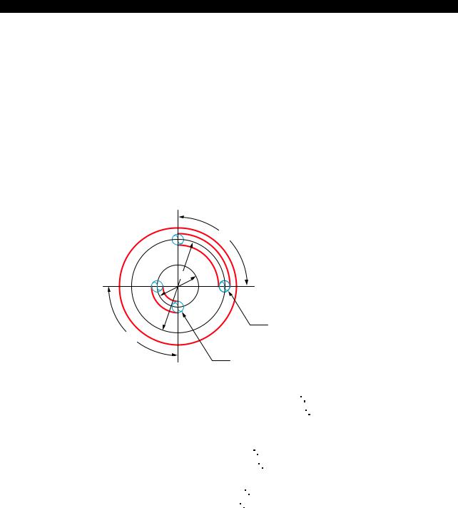
Although it is possible to machine a workpiece by controlling the C-axis, tool movement distance in unit time (one minute) differs according to the diameter of the position to be machined because the feedrate is specified in units of deg/min. This must be taken into consideration when making a program.
[Memo]
To match the unit of the C-axis feed command with the X- and/or Z-axis command, the feedrate command (F) should be calculated by converting 360 into 500 mm. This conversion should also be carried out when only a C-axis command is given.
Example:
90°
200φ
50φ
B
90°
A
Axis movement distance along slot A: π 50/4 = 39 mm
Axis movement distance along slot B: π 200/4 = 156 mm
Therefore, if cutting is carried out at a feedrate of 100 mm per minute, the feedrate (deg/min) of the C-axis is calculated as follows:
Along slot A(deg/min) 100/39 90 = 230
Along slot B(deg/min) 100/156 90 = 58
Convert the unit of feed from "deg/min" into "mm/min".
Slot A: (mm/min) 230/360 500 = 320 (F320)
Slot B: (mm/min) 58/360 500 = 80 (F80)
LE33013R0300300130001

5238-E P-11
SECTION 1 PROGRAM CONFIGURATIONS
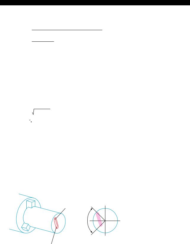
10-2. Cutting by Controlling Both C-axis and Z-axis Simultaneously
Example:
A
90° |
Point A coordinate value |
X = 80 |
|
|
Z = 100 |
|
|
C = 120 |
B |
Point B coordinate value |
X = 80 |
|
|
Z = 50 |
C = 210
LE33013R0300300140001
When cutting the spiral from A to B with a two-flute end mill under the following cutting conditions, calculate the feedrate of C-axis as explained below:
Cutting |
Feed per |
0.05 mm |
conditions: |
tooth |
|
|
M-tool speed |
400 min-1 |
Procedure :
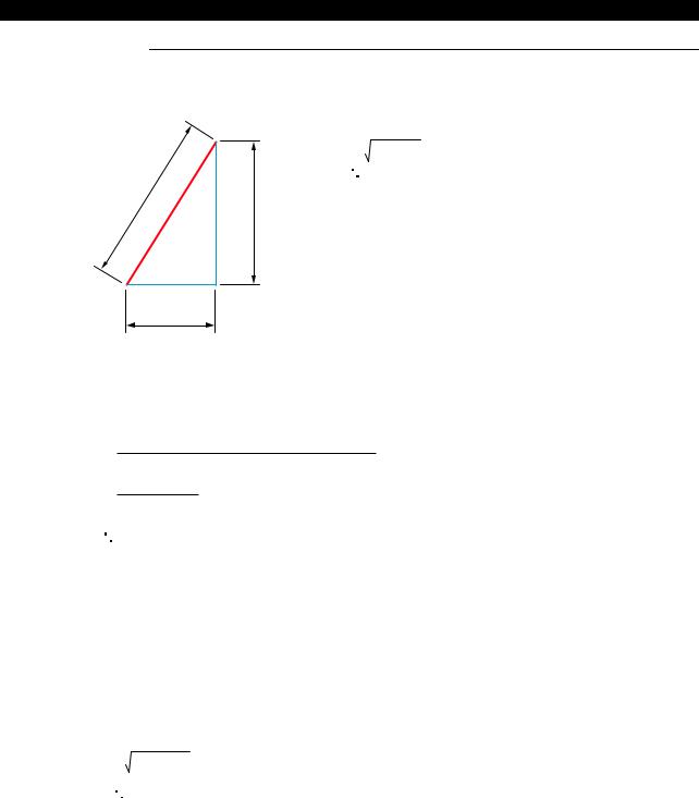
1 Calculate the distance between A and B.
A development of the diagram above is indicated below.
L2
90˚
The distance, L1, along the circumference is:
90
L L1 = 80 × π × 360 = 63 (mm)
1
The distance, L2, between A and B is:
L2 = 632+ 502 = 80 (mm)
C
50 mm
LE33013R0300300140002
5238-E P-12
SECTION 1 PROGRAM CONFIGURATIONS
2 Calculate the cutting time, T, on the basis of the cutting conditions indicated above to feed the axes along the slot.
L2
T=
(Feed per tooth) x (Number of teeth) x (min-1)
80
=
0.05 × 2 × 400
=2 (min)
LE33013R0300300140003
3 Inside the computer, the distance L3 between A and B is calculated in the following manner.
X-axis travel = 50 mm |
|
C-axis travel = 90° × 500 mm |
= 125 mm |
360° |
|
(conversion based on 360° = 500 mm)
Therefore, the distance between A and B is calculated as below:
L3 = 502+ 1252
= 135 (mm)
LE33013R0300300140004
4 The feedrate to be specified in the program is approximately calculated as below:
F = |
L3 |
= |
135 |
= 67.5 |
|
T |
2 |
||||
|
|
|
LE33013R0300300140005
Specify F67.5 in the program.
10-3. Cutting by Controlling Both C-axis and X-axis Simultaneously
Example:
A
90°
B
Point A coordinate value |
X = 80 |
|
Z = 100 |
|
C = 120 |
Point B coordinate value |
X = 40 |
|
Z = 100 |
C = 210
LE33013R0300300150001
•The cutting conditions are the same as used in "Cutting by Controlling Both C-axis and Z-axis Simultaneously".
5238-E P-13
SECTION 1 PROGRAM CONFIGURATIONS
Procedure :
1 Calculate the distance between A and B.
A
L2= 402+202
= 44.7 mm
L2
40
B
20
LE33013R0300300150002
2 Calculate the cutting time, T, on the basis of the cutting conditions indicated above to feed the axes along the slot.
L2
T =
(Feed per tooth) × (Number of teeth) × (min-1)
44.7
=
0.05× 2 × 400
=1.12 min
LE33013R0300300150003
3 Inside the computer, the distance L3 between A and B is calculated in the following manner.
X-axis travel = 40 mm
C-axis travel = 90° × 500 mm =125 mm 360°
(conversion based on 360° = 500 mm)
Therefore, the distance between A and B is calculated as below:
L3 = 402+ 1252
= 131.2 mm
LE33013R0300300150004
4 The feedrate to be specified in the program is approximately calculated as below:
F = L3 = 131.2 = 117
T 1.12
LE33013R0300300150005
Specify F117 in the program.

5238-E P-14
SECTION 1 PROGRAM CONFIGURATIONS
10-4. Cutting by Simultaneous 3-axis Control of X-, Z-, and C-axis
Example:
A
90°
B
Point A coordinate value X = 80 Z = 50 C = 120
Point B coordinate value X = 40 Z = 100 C = 210
LE33013R0300300160001
•When cutting a slot on a cone as indicated above, simultaneous 3-axis control of the X-, Z-, and C-axis becomes necessary. The feedrate to be programmed should be calculated in the following manner. Note that the example below assumes the same cutting conditions as in 11- 2. "Cutting by Controlling Both C-axis and X-axis Simultaneously".
Procedure :
1 First, consider the development of the slot on the C-axis and X-axis. In this case, calculation of the feedrate is possible in the same manner as in "Cutting by Controlling Both C-axis and X- axis Simultaneously" .
The C and X-axis travel component, L2, is:
L3 = 402+ 202
= 44.7 mm
LE33013R0300300160002
5238-E P-15
SECTION 1 PROGRAM CONFIGURATIONS
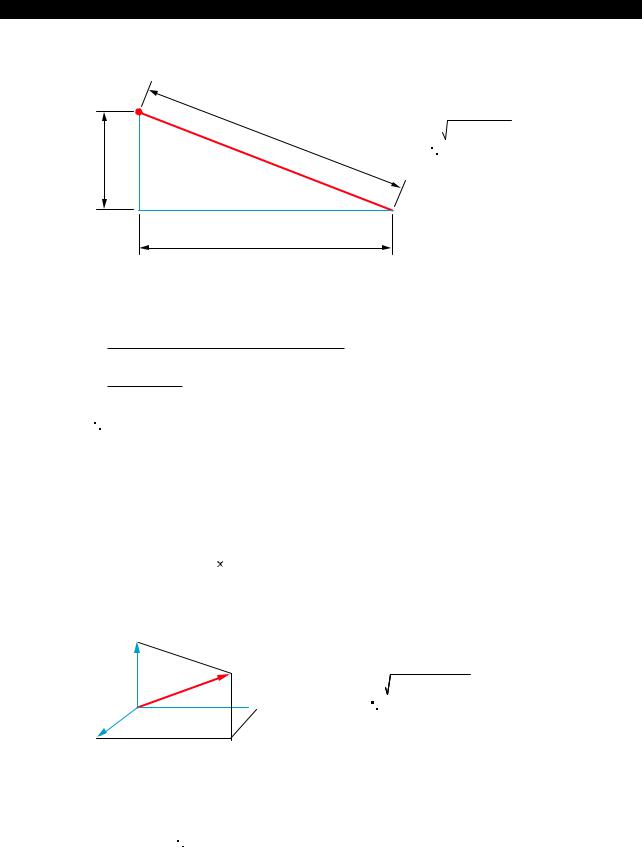
2 Calculate the actual distance between A and B from L2 calculated in (1).
A
L4 |
L4 = 44.72 + 502 |
= 67.1
L2
 B
B
Z-axis travel
LE33013R0300300160003
3 Calculate the cutting time T for distance L4:
L4
T=
(Feed per tooth) x (Number of teeth) x (min-1)
67.1
=
0.05× 2 × 400
=1.68 min
LE33013R0300300160004
4 Inside the computer, distance L5 between A and B is calculated in the following manner.
X-axis travel = 40 mm
Z-axis travel = 50 mm
500 mm = 125 mm
365
(conversion based on 360 = 500 mm)
C
L5
 Z
Z
L5 = 402+502+1252
= 140.4 mm
X
LE33013R0300300160005
5 The feedrate to be specified in the program is approximately calculated as below:
F = L5 = 140.4 = 83.6
T 1.68
LE33013R0300300160006
Specify F83.6 in the program.

5238-E P-16
SECTION 2 COORDINATE SYSTEMS AND COMMANDS
SECTION 2 COORDINATE SYSTEMS AND COMMANDS
1.Coordinate Systems
1-1. Coordinate Systems and Values
To move the tool to a target position, the reference coordinate system must be set first to define the target position, and the target position is defined by coordinate values in the set coordinate system. There are the three types of coordinate system indicated below. A program coordinate system is used for programming.
•Encoder coordinate system
•Machine coordinate system
•Program coordinate system
1-2. Encoder Coordinate System
An encoder is used to detect the position of a numerically controlled axis. The encoder coordinate system is established based on the position data output by the encoder.
The position data directly output from the encoder is not displayed on the screen, and this coordinate system may be disregarded in daily operation.
1-3. Machine Coordinate System
The reference point in the machine is referred to as the machine zero and the coordinate system which has its origin at the machine zero is called the machine coordinate system. The machine zero is set for each individual machine using system parameters and it is not necessary to change the setting after the installation of the machine.
If "0" is set for the encoder zero point offset (system parameter), the machine coordinate system agrees with the encoder coordinate system.
1-4. Program Coordinate System
The coordinate system used as the reference for program commands is called the program coordinate system.
The position of the origin of the program coordinate system varies according to the kind of workpieces to be machined and the origin is set at the required position by setting the zero offset data. The program coordinate system used for machining a specific kind of workpiece is thus defined based on the set origin.
5238-E P-17
SECTION 2 COORDINATE SYSTEMS AND COMMANDS
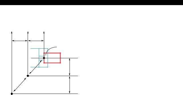
Although the origin of a program coordinate system (program zero) can be set at any position, it is usually set on the centerline of a workpiece for the X-axis and at the left end face of workpiece for the Z-axis.
Zd |
Zm |
Zp |
|
Z1 |
|
Z2 |
|
|
|
|
Program zero |
|
|
|
Program coordinate |
|
|
|
system |
|
|
|
Xp |
|
|
|
X2 |
|
|
Machine coordinate |
|
|
|
system |
Xm |
|
|
|
|
|
Machine zero |
X1 |
|
|
|
|
|
|
|
|
Xd |
Zero point of encoder
Xd, Zd : Output value of position encoder (0: Zero point of position encoder)
Xm, Zm : Coordinate values in the machine coordinate system (0: Machine zero)
Xp, Zp |
: Coordinate values in the program coordinate system |
|
(0: Program zero) |
X1, Z1 |
: Offset amount of position encoder |
X1, Z1 |
: Offset amount of position encoder |
LE33013R0300400040001
 Loading...