


CNC SYSTEM
OSP-P200L
MACTURN/MULTUS Series
OPERATION MANUAL
(4th Edition)
Pub No. 5262-E-R3 (LE32-114-R4) Feb. 2007

5262-E P-(i)
SAFETY PRECAUTIONS
SAFETY PRECAUTIONS
The machine is equipped with safety devices which serve to protect personnel and the machine itself from
hazards arising from unforeseen accidents. However, operators must not rely exclusively on these safety
devices: they must also become fully familiar with the safety guidelines presented below to ensure accidentfree operation.
This instruction manual and the warning signs attached to the machine cover only those hazards which
Okuma can predict. Be aware that they do not cover all possible hazards.
1. Precautions Relating to Installation
(1) Please be noted about a primary power supply as follows.
• Do not draw the primary power supply from a distribution panel that also supplies a major
noise source (for example, an electric welder or electric discharge machine) since this
could cause malfunction of the CNC unit.
• If possible, connect the machine to a ground not used by any other equipment. If there is
no choice but to use a common ground, the other equipment must not generate a large
amount of noise (such as an electric welder or electric discharge machine).
(2) Installation Environment
Observe the following points when installing the control enclosure.
• Make sure that the CNC unit will not be subject to direct sunlight.
• Make sure that the control enclosure will not be splashed with chips, water, or oil.
• Make sure that the control enclosure and operation panel are not subject to excessive
vibrations or shock.
• The permissible ambient temperature range for the control enclosure is 5 to 40°C.
• The permissible ambient humidity range for the control enclosure is relative humidity 50%
or less at 40°C (no condensation).
• The maximum altitude at which the control enclosure can be used is 1000 m (3281ft.).
2. Points to Check before Turning on the Power
(1) Close all the doors of the control enclosure and operation panel to prevent the entry of water,
chips, and dust.
(2) Make absolutely sure that there is nobody near the moving parts of the machine, and that there
are no obstacles around the machine, before starting machine operation.
(3) When turning on the power, turn on the main power disconnect switch first, then the CONTROL
ON switch on the operation panel.

5262-E P-(ii)
SAFETY PRECAUTIONS
3. Precautions Relating to Manual/Continuous Operation
(1) Follow the instruction manual during operation.
(2) Do not operate the machine with the front cover, chuck cover, or another protective cover
removed.
(3) Close the front cover before starting the machine.
(4) When machining the initial workpiece, check for machine operations, run the machine under no
load to check for interference among components, cut the workpiece in the single block mode,
and then start continuous operation.
(5) Ensure your safety before rotating the spindle or moving a machine part.
(6) Do not touch chips or workpiece while the spindle is rotating.
(7) Do not stop a rotating part with hand or another means.
(8) Check that the condition of hydraulic chuck jaws as mounted, operating pressure, and maxi-
mum permissible revolving speed.
(9) Check the condition and location of the cutting tool as mounted.
(10) Check the tool offset value.
(11) Check the zero offset value.
(12) Check that the SPINDLE OVERRIDE and FEEDRATE OVERRIDE dials on the NC operation
panel are set to 100%.
(13) When moving the turret, check the software limits for X- and Z-axes or the locations of limit
switch dogs to prevent interference with the chuck and tailstock.
(14) Check the location of the turret.
(15) Check the location of the tailstock.
(16) Cut workpieces with a transmitted power and torque within the permissible range.
(17) Chuck each workpiece firmly.
(18) Check that the coolant nozzle is properly located.
4. Precautions Relating to the ATC
(1) The tool clamps of the magazine, spindle, etc., are designed for reliability, but it is possible that
a tool could be released and fall in the event of an unforeseen accident, exposing you to
danger: do not touch or approach the ATC mechanism during ATC operation.
(2) Always inspect and change tools in the magazine in the manual magazine interrupt mode.
(3) Remove chips adhering to the magazine at appropriate intervals since they can cause
misoperation. Do not use compressed air to remove these chips since it will only push the chips
further in.
(4) If the ATC stops during operation for some reason and it has to be inspected without turning the
power off, do not touch the ATC since it may start moving suddenly.

5262-E P-(iii)
SAFETY PRECAUTIONS
5. On Finishing Work
(1) On finishing work, clean the vicinity of the machine.
(2) Return the ATC, APC and other equipment to the predetermined retraction position.
(3) Always turn off the power to the machine before leaving it.
(4) To turn off the power, turn off the CONTROL ON switch on the operation panel first, then the
main power disconnect switch.
6. Precautions during Maintenance Inspection and When Trouble Occurs
In order to prevent unforeseen accidents, damage to the machine, etc., it is essential to observe the
following points when performing maintenance inspections or during checking when trouble has
occurred.
(1) When trouble occurs, press the emergency stop button on the operation panel to stop the
machine.
(2) Consult the person responsible for maintenance to determine what corrective measures need
to be taken.
(3) If two or more persons must work together, establish signals so that they can communicate to
confirm safety before proceeding to each new step.
(4) Use only the specified replacement parts and fuses.
(5) Always turn the power off before starting inspection or changing parts.
(6) When parts are removed during inspection or repair work, always replace them as they were
and secure them properly with their screws, etc.
(7) When carrying out inspections in which measuring instruments are used - for example voltage
checks - make sure the instrument is properly calibrated.
(8) Do not keep combustible materials or metals inside the control enclosure or terminal box.
(9) Check that cables and wires are free of damage: damaged cables and wires will cause current
leakage and electric shocks.
(10) Maintenance inside the Control Enclosure
a. Switch the main power disconnect switch OFF before opening the control enclosure door.
b. Even when the main power disconnect switch is OFF, there may some residual charge in
the MCS drive unit (servo/spindle), and for this reason only service personnel are permitted
to perform any work on this unit. Even then, they must observe the following precautions.
• MCS drive unit (servo/spindle)
The residual voltage discharges two minutes after the main switch is turned OFF.

c. The control enclosure contains the NC unit, and the NC unit has a printed circuit board
whose memory stores the machining programs, parameters, etc. In order to ensure that the
contents of this memory will be retained even when the power is switched off, the memory
is supplied with power by a battery. Depending on how the printed circuit boards are handled, the contents of the memory may be destroyed and for this reason only service personnel should handle these boards.
(11) Periodic Inspection of the Control Enclosure
a. Cleaning the cooling unit
The cooling unit in the door of the control enclosure serves to prevent excessive temperature rise inside the control enclosure and increase the reliability of the NC unit. Inspect the
following points every three months.
• Is the fan motor inside the cooling unit working?
The motor is normal if there is a strong draft from the unit.
• Is the external air inlet blocked?
If it is blocked, clean it with compressed air.
7. General Precautions
5262-E P-(iv)
SAFETY PRECAUTIONS
(1) Keep the vicinity of the machine clean and tidy.
(2) Wear appropriate clothing while working, and follow the instructions of someone with sufficient
training.
(3) Make sure that your clothes and hair cannot become entangled in the machine. Machine opera-
tors must wear safety equipment such as safety shoes and goggles.
(4) Machine operators must read the instruction manual carefully and make sure of the correct pro-
cedure before operating the machine.
(5) Memorize the position of the emergency stop button so that you can press it immediately at any
time and from any position.
(6) Do not access the inside of the control panel, transformer, motor, etc., since they contain high-
voltage terminals and other components which are extremely dangerous.
(7) If two or more persons must work together, establish signals so that they can communicate to
confirm safety before proceeding to each new step.

8. Symbols Used in Manual
The following warning indications are used in this manual to draw attention to information of particular importance. Read the instructions marked with these symbols carefully and follow them.
DANGER
indicates an imminently hazardous situation which, if not avoided, will result in death or serious
injury.
WARNING
indicates a potentially hazardous situation which, if not avoided, could result in death or serious
injury.
CAUTION
indicates a potentially hazardous situation which, if not avoided, may result in minor or moderate injury.
CAUTION
5262-E P-(v)
SAFETY PRECAUTIONS
indicates a potentially hazardous situation which, if not avoided, may result in damage to your
property.
SAFETY INSTRUCTIONS
indicates general instructions for safe operation.

5262-E P-(i)
INTRODUCTION
INTRODUCTION
Thank you very much for choosing our CNC system. This numerical control system is a expandable CNC
with various features . Major features of the CNC system are described below.
(1) Compact and highly reliable
The CNC system has become compact and highly reliable because of advanced hardware technology,
including computer boards equipped with high-speed micro processors, I/O link, and servo link. The
‘variable software’ as a technical philosophy of the OSPs supported by a hard disk. Functions may be
added to the CNC system as required after delivery.
(2) NC operation panels
The following types of NC operation panels are offered to improve the user-friendliness.
• Thin color operation panels (horizontal)
• Thin color operation panels (vertical)
One or more of the above types may not be used for some models.
(3) Machining management functions
These functions contribute to the efficient operation of the CNC system and improve the profitability from
small quantity production of multiple items and variable quantity production of variations. Major control
functions are described below.
a. Reduction of setup time
With increase in small-volume production, machining data setting is more frequently needed. The
simplified file operation facilitates such troublesome operation. The documents necessary for setup,
such as work instructions, are displayed on the CNC system to eliminate the necessity of controlling
drawings and further reduce the setup time.
b. Production Status Monitor
The progress and operation status can be checked on a real-time basis on the screen of the CNC
system.
c. Reduction of troubleshooting time
Correct information is quickly available for troubleshooting.
(4) Help functions
When an alarm is raised, press the help key to view the content of the alarm.
This helps take quick action against the alarm.
To operate the CNC system to its maximum performance, thoroughly read and understand this instruction
manual before use.
Keep this instruction manual at hand so that it will be available when you need a help.
Screens
Different screens are used for different models. Therefore, the
screens used on your CNC system may differ from those shown
in this manual.

5262-E P-(i)
TABLE OF CONTENTS
TABLE OF CONTENTS
SECTION 1 TURRET OPERATION.............................................................................1
1. Overview.................................................................................................................................. 1
2. Turret Indexing Control............................................................................................................ 2
2-1. Turret Index Position ........................................................................................................ 2
2-2. Turret Number Assignment .............................................................................................. 3
2-3. Turret Indexing Turret Control .......................................................................................... 4
3. Turret B-axis Positioning Control.............................................................................................5
3-1. B-axis Positioning ............................................................................................................. 5
3-2. Movable Range of the B-axis ........................................................................................... 5
3-3. Precautions for B-axis positioning control ........................................................................ 6
4. Turret Indexing Commands ..................................................................................................... 7
4-1. Command Systems .......................................................................................................... 7
4-2. Base cutting Position Indexing by Tool Numbers ............................................................. 7
4-3. Vertical Cutting Position Indexing by Tool Numbers ........................................................ 7
4-4. Base cutting Position Indexing by Tool Group Numbers .................................................. 8
4-5. Vertical Cutting Position Indexing by Tool Group Numbers ............................................. 8
4-6. Base cutting Position Indexing by Turret Numbers .......................................................... 8
4-7. Vertical Cutting Position Indexing by Turret Numbers...................................................... 9
4-8. ATC Position Indexing by Turret Numbers ....................................................................... 9
4-9. Independent Direction of the Tool Compensation Number, the Nose R Com-
pensation Number, and the Tool Diameter Compensation Number................................. 9
5. Turret B-axis Positioning Commands .................................................................................... 10
5-1. Command Systems ........................................................................................................ 10
5-2. B-axis Positioning Command in the Same Block as the TL Command.......................... 11
5-3. B-axis Positioning Command in the Same Block as the TG Command ......................... 11
5-4. B-axis Positioning Command in the Same Block as the T Command............................ 12
5-5. Independent Command for Positioning B-axis ............................................................... 12
5-6. Turret Rotary Position Offset Command in B-axis Positioning (G52)............................. 13
5-7. Terms Relevant to Turret Rotary Position Compensation .............................................. 14
6. Manual Turret Indexing Operation ......................................................................................... 15
6-1. Turret Indexing Position.................................................................................................. 15
6-2. H1 Turret ........................................................................................................................ 15
7. Manual B-axis Positioning Operation..................................................................................... 16
7-1. Positioning the B-axis ..................................................................................................... 16
7-2. Canceling B-axis positioning .......................................................................................... 16
7-3. BA Angle Data Display ................................................................................................... 17
8. Manual Slant Feed Function.................................................................................................. 18
8-1. Designating a Slant Feed Direction ................................................................................ 18
8-2. Selecting Slant Feed, Feed Operation ........................................................................... 19
8-3. Caution on Recovering from Manual Intervention .......................................................... 20
8-4. Relationship with the Slant Compound Fixed Cycle Function ........................................ 20

5262-E P-(ii)
TABLE OF CONTENTS
8-5. Others............................................................................................................................. 20
9. Tool Index Function ............................................................................................................... 21
9-1. Relation between Turret Indexing and Tool Indexing ..................................................... 21
9-2. Relation between Tool Indexing and Graphic Display .................................................... 21
9-3. Relation between Tool Index Command and Tool Compensation ................................. 22
9-4. Tool Index Commands ................................................................................................... 22
9-5. Relation between Rotary Tool and Tool Index Commands ............................................ 22
10.Parameter Settings ................................................................................................................ 23
10-1.B-axis User Parameters ................................................................................................ 23
10-2.B-axis System Parameters ............................................................................................ 23
10-3.Turret Position Error Compensation .............................................................................. 23
10-4.B-axis Indexing Angles .................................................................................................. 23
10-5.M-axis Orientation .........................................................................................................24
10-6.System Parameters ....................................................................................................... 24
10-7.Optional Parameters...................................................................................................... 25
10-8.Machine System Parameters ........................................................................................ 25
11.Tool Data Setting ................................................................................................................... 26
11-1.Tool Shape Data............................................................................................................26
11-2.Tool Compensation ....................................................................................................... 27
11-3.Tool Life Management (Special Function)..................................................................... 28
12.Tool Compensation Multi-System Function ........................................................................... 29
12-1.Combinations of Compensation Systems...................................................................... 29
12-2.Tool Compensation Data Structure ............................................................................... 30
12-3.Selecting the TOOL COMPENSATION Screen with the Tool Compensation
Multi-system Function..................................................................................................... 32
12-4.Tool Life Management Tool Information Screen for the Tool Compensation
Multi-system Function..................................................................................................... 32
12-5.System Variables...........................................................................................................33
13.Other Functions ..................................................................................................................... 34
13-1.Tool Compensation Automatic Calculation Function..................................................... 34
13-2.Turret Coolant Interlock ................................................................................................. 34
13-3.Data Input/Output Function ........................................................................................... 35
13-4.Interlock ......................................................................................................................... 37
SECTION 2 ATC OPERATION ..................................................................................38
1. Overview................................................................................................................................ 38
2. Machine Specifications.......................................................................................................... 38
2-1. Outline of the Machine.................................................................................................... 38
2-2. Machine Operation ......................................................................................................... 41
2-3. ATC Operation................................................................................................................ 42
3. ATC Logic Tables .................................................................................................................. 44
3-1. Input Logic Tables ..........................................................................................................44
3-2. Output Logic Tables ....................................................................................................... 45
3-3. Manual Interlock Tables ................................................................................................. 45

5262-E P-(iii)
TABLE OF CONTENTS
4. Manual Operation .................................................................................................................. 46
4-1. Manual Magazine Operation .......................................................................................... 46
4-2. Manual ATC Operation................................................................................................... 55
5. ATC Program Commands ..................................................................................................... 59
5-1. ATC Commands ............................................................................................................. 59
5-2. ATC Macro Commands .................................................................................................. 61
5-3. Others............................................................................................................................. 62
5-4. Example Programs ......................................................................................................... 63
6. Automatic Operation .............................................................................................................. 67
6-1. Sequence Return Procedure .......................................................................................... 67
6-2. Cautions on Using the Program Check/Graphic Scale Automatic Setting Func-
tion while in Machine Lock Status .................................................................................. 69
7. Data Setting ........................................................................................................................... 71
7-1. Magazine Information ..................................................................................................... 71
7-2. Tool Information.............................................................................................................. 74
8. ATC Status Display................................................................................................................ 75
8-1. ATC Status Display Screen ............................................................................................ 75
8-2. Tool Data Display Screen............................................................................................... 77
8-3. Machine Diagnosis Screen............................................................................................. 78
8-4. ATC Input/Output Display Screen .................................................................................. 81
9. Parameter Setting.................................................................................................................. 82
9-1. ATC Tool Change Position and Movable Range............................................................ 82
9-2. Magazine Axis Parameter .............................................................................................. 83
9-3. EC–axis (Tool Change Arm Rotation Axis) Parameter................................................... 84
9-4. EZ–axis (Tool Change Advance/Retraction Rotation Axis) Parameter (MUL-
TUS-B300/B400) ............................................................................................................ 84
9-5. Positioning Point EC (MULTUS-B300/B400).................................................................. 85
9-6. Positioning Point EZ (MULTUS-B300/B400) .................................................................. 85
9-7. Turret Index Angle ..........................................................................................................85
9-8. Magazine Panel Communication Parameter .................................................................. 86
9-9. Setting the Tool Change Arm Rotation Positions Immediately after Installing
the Control Software (MULTUS-B300/B400).................................................................. 87
9-10.Cam Shaft Timing Parameter (Machine System Parameter No.18-1) .......................... 88
9-11.Step Division Parameter................................................................................................ 89
9-12.ATC Tool Change Arm (Machine System Parameter No.18-2)..................................... 90
9-13.Tool Change Arm Torque Limit Parameter (Machine System Parameter
No.18-3).......................................................................................................................... 90
9-14.Tool Change Arm Override 1 (Machine System Parameter No.18-4) ........................... 90
9-15.Tool Change Arm Override 2, 3 (Machine System Parameter No.18-5, 6) ................... 91
10.System Check........................................................................................................................ 92
10-1.System Check Mode Parameters.................................................................................. 92
10-2.ATC Parameters............................................................................................................ 94
10-3.Manual ATC Operation.................................................................................................. 97
11.Others .................................................................................................................................. 100
11-1.G and M Code Macro Functions.................................................................................. 100

5262-E P-(iv)
TABLE OF CONTENTS
11-2.ATC Macro Command Subprograms .......................................................................... 102
11-3.Optical In–process Workpiece Gauging Specification (Optional Specification).............. 108
11-4.At the Occurrence of ATC Failure ............................................................................... 109
SECTION 3 Y-AXIS CONTROL ...............................................................................112
1. OUTLINE Y-AXIS CONTROL.............................................................................................. 112
1-1. OVERVIEW .................................................................................................................. 112
2. OPERATION........................................................................................................................ 113
2-1. MACHINE OPERATION............................................................................................... 113
2-2. MANUAL OPERATION ................................................................................................ 116
2-3. MDI OPERATION......................................................................................................... 118
2-4. AUTOMATIC OPERATION .......................................................................................... 118
2-5. NC OPERATION PANEL DISPLAY ............................................................................. 119
2-6. ADDITIONAL FUNCTIONS .......................................................................................... 121
3. PROGRAMMING................................................................................................................. 130
3-1. OVERVIEW .................................................................................................................. 130
3-2. Y-AXIS CONTROL COMMANDS................................................................................. 130
3-3. Y-AXIS COMPOUND FIXED CYCLES ........................................................................ 134
4. Slant Machining Mode Function .......................................................................................... 145
4-1. Overview....................................................................................................................... 145
4-2. Coordinate System for Slant Machining ....................................................................... 146
4-3. Slant Machining Mode Commands............................................................................... 148
4-4. Functions Usable in Slant Machining Mode ................................................................. 149
4-5. Zero Point Shift Macro Command ................................................................................ 152
4-6. Actual Position Display ................................................................................................. 153
5. DATA OPERATION ............................................................................................................. 154
5-1. DATA OPERATION...................................................................................................... 154
6. PARAMETER ...................................................................................................................... 161
6-1. PARAMETER ............................................................................................................... 161
7. APPENDIX........................................................................................................................... 165
7-1. Y-AXIS MACHINING EXAMPLES (FOR A-TURRET SIDE ONLY).............................. 165
SECTION 4 SUB-SPINDLE OPERATION ...............................................................169
1. Overview.............................................................................................................................. 169
1-1. Overview....................................................................................................................... 169
1-2. Machine Configuration.................................................................................................. 169
1-3. Coordinate System ....................................................................................................... 170
2. Operation Panels................................................................................................................. 171
2-1. Basic Configuration of Operation Panels...................................................................... 171
2-2. Option Panel for Sub-spindle Machines ....................................................................... 172
2-3. Brief Explanation of the Panels .................................................................................... 173
3. Manual Operation ................................................................................................................ 175
3-1. Operations Related to the Spindle 1 (Main Spindle) .................................................... 175

5262-E P-(v)
TABLE OF CONTENTS
3-2. Operations Related to the Spindle 2 (Sub Spindle) ...................................................... 177
3-3. Axis Feed Operation (X–, Z–, C–, and W–axis) ........................................................... 179
3-4. M-TOOL SPINDLE OPERATION ................................................................................. 182
3-5. Other Manual Operations ............................................................................................. 184
4. MDI/Automatic Operation .................................................................................................... 185
4-1. Coordinate System Selection ....................................................................................... 185
4-2. MDI Operation .............................................................................................................. 186
4-3. Automatic Operation..................................................................................................... 186
5. Additional Functions ............................................................................................................ 187
5-1. Workpiece Transfer Function from the Main Spindle to the Sub Spindle ..................... 187
5-2. Z–axis Mirror Image...................................................................................................... 188
5-3. Interlock (for two-saddle models only) .......................................................................... 192
5-4. W-axis Cutting Function (Optional)............................................................................... 193
6. Programming ....................................................................................................................... 195
6-1. Coordinate System ....................................................................................................... 195
6-2. Program Commands .................................................................................................... 197
7. Data Operation .................................................................................................................... 199
7-1. Zero Setting .................................................................................................................. 199
8. Description of Parameters ................................................................................................... 203
8-1. System Parameters ...................................................................................................... 203
8-2. User Parameters .......................................................................................................... 204
8-3. Chuck Parameters........................................................................................................ 205
8-4. Machine System Parameter (Airblow/Coolant)............................................................. 207
8-5. Machine User Parameter (Airblow/Coolant) ................................................................. 210
8-6. Machine User Parameter (Chuck) ................................................................................ 211
8-7. Machine User Parameter (Spindle) .............................................................................. 212
8-8. Machine System Parameter (Spindle).......................................................................... 213
8-9. Machine System Parameter (Door Interlock) ............................................................... 214
8-10.Machine System Parameter (Milling Spindle).............................................................. 215
SECTION 5 MULTI-EDGE TOOL FUNCTION FOR 8-/12-ANGLE INDEX-
ING.......................................................................................................216
1. Overview.............................................................................................................................. 216
2. Function............................................................................................................................... 217
2-1. Tool Management......................................................................................................... 217
2-2. Turret Rotation.............................................................................................................. 218
2-3. Edge Index Command.................................................................................................. 219
2-4. Interlock ........................................................................................................................ 219
3. Tool Data Setting Screen..................................................................................................... 220
3-1. TOOL SHAPE Screen .................................................................................................. 220
3-2. TOOL LIFE MANAGEMENT Screen (for the Machine with Tool Life Manage-
ment FUnction) ............................................................................................................. 221
3-3. GROUP TABLE Screen (for the Machine with Tool Life Management Func-
tion)............................................................................................................................... 223

5262-E P-(vi)
TABLE OF CONTENTS
4. System Variable................................................................................................................... 224
4-1. Internal Tool Number.................................................................................................... 224
4-2. System Variable for Internal Tool Number ................................................................... 225
4-3. System Variable for Tool Group ................................................................................... 226
4-4. System Variable for Turret Number.............................................................................. 226
4-5. System Variables with No Subscript............................................................................. 226
SECTION 6 NC TAILSTOCK (MULTUS-B300/B400) ..............................................227
1. Operation............................................................................................................................. 228
1-1. Setup Operation ........................................................................................................... 228
1-2. Ordinary Operation ....................................................................................................... 228
2. Tailstock Movement............................................................................................................. 229
2-1. Manual Tailstock Movement......................................................................................... 229
2-2. Automatic Tailstock Movement..................................................................................... 229
3. Switching between High/Low Pressure ............................................................................... 230
3-1. Switching between High/Low Pressure Command....................................................... 230
3-2. Operation...................................................................................................................... 230
4. Multiple Sizing Position Command ...................................................................................... 231
4-1. Multiple Sizing Position Command ............................................................................... 231
4-2. Operation...................................................................................................................... 231
4-3. Sequence Restoration (operation starting from the halfway of the program) ............... 231
5. Preparatory Operation .........................................................................................................232
5-1. Setting the Sizing Position............................................................................................ 232
5-2. No-load Torque Measurement...................................................................................... 233
6. Parameters .......................................................................................................................... 234
6-1. NC Tailstock User Parameter....................................................................................... 234
6-2. NC Tailstock System Parameter .................................................................................. 238
7. Interlock ............................................................................................................................... 240
SECTION 7 OTHER FUNCTIONS...........................................................................243
1. Description of Other Functions ............................................................................................ 243
1-1. Override for Internal Arc Cutting................................................................................... 243
1-2. Helical Cutting Function (Optional)............................................................................... 245
SECTION 8 APPENDIX...........................................................................................246
1. Logic Tables ........................................................................................................................ 246
2. ATC Input/Output Bit Tables................................................................................................ 269
3. List of Data Formats ............................................................................................................ 283
3-1. Tool data setting (T) ..................................................................................................... 283
3-2. Zero point data setting (0) ............................................................................................ 284
3-3. Parameter setting (P) ................................................................................................... 285

5262-E P-(i)
CONTENTS
CONTENTS
SECTION 1 TURRET OPERATION
SECTION 2 ATC OPERATION
SECTION 3 Y-AXIS CONTROL
SECTION 4 SUB-SPINDLE OPERATION
SECTION 5 MULTI-EDGE TOOL FUNCTION FOR 8-/12-ANGLE INDEX-
ING
SECTION 6 NC TAILSTOCK (MULTUS-B300/B400)
SECTION 7 OTHER FUNCTIONS
SECTION 8 APPENDIX

SECTION 1 TURRET OPERATION
1. Overview
This section describes the functions and operations of the turrets installed in MACTURN and MULTUS series.
MACTURN and MULTUS series can move its saddle in three directions X-axis, Y-axis, and Z-axis.
The turret rotates around the Y-axis.
The turret indexing function is available in two modes: “B-axis 1° indexing” by 1°, and “B-axis 1/
1000° indexing” by 0.001°. However, only “B-axis 1/1000° indexing” is available in MULTUS series.
B-axis indexing type
1° indexing 1/1000° indexing
MACTURN 250/350/550 Available Available
MULTUS B300/B400 Not available Available
5262-E P-1
SECTION 1 TURRET OPERATION

2. Turret Indexing Control
Since the turret of MACTURN and MULTUS series rotates around the Y-axis, a single tool can be
used on the front or on a side according to the direction the turret is indexed.
2-1. Turret Index Position
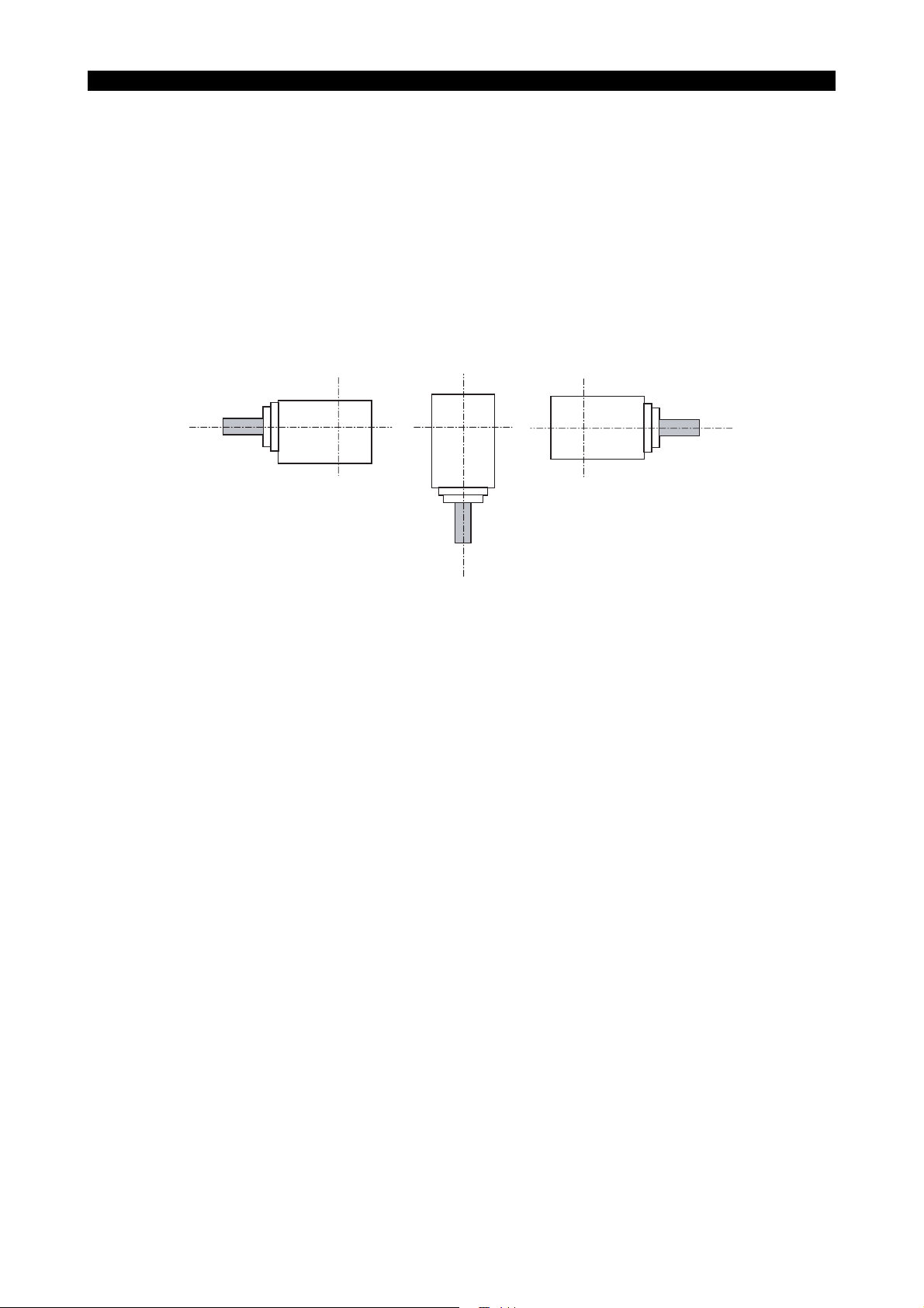
(1) Base cutting position
One of the basic indexing operations of the turret for MACTURN and MULTUS series machines
is “base cutting position” indexing. The base cutting position means the state the tool attached
faces the Z-axis direction. When a second spindle is equipped, the turret indexing position is
180 degrees shifted from the base cutting position.
(2) Vertical cutting position
The “vertical cutting position” is the state the B-axis is shifted 90 degrees from the base cutting
position in the positive direction. In this position, the tool attached faces the X-axis direction.
(3) ATC position
MACTURN and MULTUS series are generally equipped with an ATC. To mount a tool to the turret using an ATC, the saddle must be moved to the position where the tool can be replaced, and
the turret must be indexed to the ATC position in advance. On MACTURN and MULTUS series
machines, the ATC position and the turret indexing angle to the base cutting position are the
same.
Although physical turret indexing is the same, the control mode may be different.
5262-E P-2
SECTION 1 TURRET OPERATION
• H1 turret
First spindle
base cutting
position
Second spindle
base cutting
position
Vertical cutting position
LE32114R0400300030001
2-2. Turret Number Assignment
A general turret, for example an octagonal turret, is indexed with index numbers 1 to 8. The turret for
MACTURN and MULTUS series machines, on the other hand, can use a single tool in two different
indexing positions, which means both the H1 turrets are internally controlled as square turrets in the
NC.
With a regular turret indexing command (such as T0100 and T0300), the turret number NC has
internally assigned will be indexed to the base cutting position.
H1 turret numbers
Although only one tool can be attached to the H1 turret, turret numbers 1 to 3 are assigned to it. The
turret can, therefore, be indexed as shown below with a T command, but to which direction the tool
will be faced will generally be directed.
5262-E P-3
SECTION 1 TURRET OPERATION
T1
T3
T2
LE32114R0400300040001
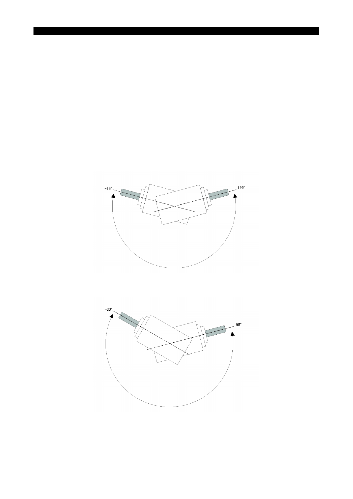
2-3. Turret Indexing Turret Control
The H1 turret cannot make a full turn because of the structure of the turret, and moves like a turret
within a specific range as shown below.
In a machine with a turret indexing single-direction positioning function (*) for turret control, an error
will occur if an overshoot in a single direction is in the turret indexing prohibition range.
* Such a machine positions the B-axis from the B-axis negative direction to the positive direction,
irrespective of the position of the target point. With a command of positioning to a smaller angle
than the current one, the B-axis will move to -10 degrees and then in the positive direction to
the target point.
H1 turret
The MACTURN series can rotate the H1 turret between -15° and +195° and MULTUS series
machine can rotate between -30° and +195° with the base cutting position set at 0°.
It will be indexed in the order of T1 → T2 → T3 → T2 → T1 → T2... with the manual turret swing button.
5262-E P-4
SECTION 1 TURRET OPERATION
LE32114R0400300050001
LE32114R0400300050002

3. Turret B-axis Positioning Control
When “B-axis one-degree indexing mode” or “B-axis 1/1000-degree pitch indexing mode” is
selected, the B-axis can be positioned to any set angle. This B-axis positioning control function is
available for machining inclined faces.
3-1. B-axis Positioning
The B-axis can be positioned with only an MDI command or program command. To perform manual
operation with the B-axis positioned, the B-axis must be positioned in advance by MDI operation.
For specific B-axis positioning commands, see 5. “Turret B-axis Positioning Commands”.
3-2. Movable Range of the B-axis
In B-axis positioning, the angular reference for the B-axis angle command is different depending on
the turret Indexed state. Basically, the increment in the B-axis angle from the turret indexing position
as the reference is directed.
Depending on the turret indexing position, an error will occur if he B-axis positioning angle is out of
the movable range.
Set the movable range with the mechanical system parameters “turret boundary angle” and “turret
angle range.”
5262-E P-5
SECTION 1 TURRET OPERATION
H1 turret
Assuming that the indexed angle of the B-axis with T1 as the base cutting position is 0.000°, the Baxis positioning command range for MACTURN series is between -30° and +195° and MULTUS
series is -30° and +195°.
LE32114R0400300080001
LE32114R0400300080002

3-3. Precautions for B-axis positioning control
(1) The B-axis positioning data just after software installation is 0 degrees.
(2) Issue a B-axis angle data command in the “BA=” format.
(3) A B-axis positioning command must be set in the same block as a turret indexing command.
(4) “BA = 0” will be considered directed when only a turret indexing command is issued.
(5) After the operation mode is switched from automatic or MFI operation to manual operation, the
angle data for the B-axis positioning command remains valid. The B-axis angle data is backed
up in real time and will be retained even after the power is turned OFF.
(6) The B-axis positioning angle data is displayed as current position data. However, if there is a
difference of more than 0.5 degrees between the directed B-axis position and the angle of the
B-axis actually positioned, the current position will be displayed as “.” In this case, the
current position will be displayed in the normal manner by swinging the turret again.
(7) The direction of the B-axis coordinates generally depends on the direction of the Y-axis coordi-
nates. MACTURN and MULTUS series machines, however, always treat the counterclockwise
direction as the B-axis positive direction. This direction will not be affected by Y-axis mirror
images that will be described later. On machines equipped with a sub-spindle, the clockwise
direction viewed from the turret is the B-axis positive direction when the coordinate system for
the second spindle mode is selected.
5262-E P-6
SECTION 1 TURRET OPERATION

4. Turret Indexing Commands
A wide variety of directing methods are available for turret indexing according to the purpose.
First understand the outline of the command systems, and see details of the directing methods.
4-1. Command Systems
Command
TL
TG
T
TC
Directing turret indexing with the tool
number as an argument.
Directing turret indexing with the tool
group number as an argument.
Directing turret indexing with the turret number as an argument.
Indexing the turret to the ATC position with the turret number as an
argument.
Purpose
5262-E P-7
SECTION 1 TURRET OPERATION
Base cutting
position indexing
Vertical cutting
position indexing
TL=rr t t oo BT=0
TL=rr t t oo BT=1
TG=gg BT=0
TG=gg BT=1
Trr t t oo TP=0 The TP command must exist
Trr t t oo TP=1
TC=nn
The BT command must exist
in the same block as the TL
or TG command.
in the same block as the T
command.
Remarks
rr: Nose R compensation number
tt: Tool number
oo: Tool compensation number
nn: Turret number
4-2. Base cutting Position Indexing by Tool Numbers
TL = r r t t oo BT = 0
TL = t t tooo BT = 0Number of tool life control sets: 200
This command indexes the tool of the number specified in [tt] to the base cutting position.
• Commands for BT = 0 can be omitted.
• With regard to 200 tool life control sets, specify a tool number in [ttt] and a tool compensation
number in [ooo]. The same number as the tool compensation number will be selected as the
nose R compensation number.
4-3. Vertical Cutting Position Indexing by Tool Numbers
TL = r r t t oo BT = 1
TL = t t tooo BT = 1Number of tool life control sets: 200
This command indexes the tool of the number specified in [ttt] to the vertical cutting position.
• With regard to 200 tool life control sets, specify a tool number in [ttt] and a tool compensation
number in [ooo]. The same number as the tool compensation number will be selected as the
nose R compensation number.

SECTION 1 TURRET OPERATION
4-4. Base cutting Position Indexing by Tool Group Numbers
TG = gg BT = 0
TG = ggg BT = 0 Number of tool life control sets: 200
This command indexes the tool of the tool group number specified in [gg] to the base cutting position.
• Commands for BT = 0 can be omitted.
• With regard to 200 tool life control sets, specify a tool group number in [ggg].
• Specify an offset group with OG = [1/2/3].
• The same number as the tool compensation number will be selected as the nose R compensa-
tion number.
4-5. Vertical Cutting Position Indexing by Tool Group Numbers
TG = gg BT = 1
TG = ggg BT = 1 Number of tool life control sets: 200
5262-E P-8
This command indexes the tool of the tool group number specified in [gg] to the vertical cutting position.
• With regard to 200 tool life control sets, specify a tool group number in [ggg].
• Specify an offset group with OG = [1/2/3].
• The same number as the tool compensation number will be selected as the nose R compensa-
tion number.
4-6. Base cutting Position Indexing by Turret Numbers
T r r n n oo TP = 0
T n n ooo TP = 0 Number of tool life control sets: 200
This command indexes the turret of the number specified in [tt] to the base cutting position and
begins cutting with the tool attached in the base cutting position.
• With regard to 200 tool life control sets, specify a tool compensation number in [ooo]. The same
number as the tool compensation number will be selected as the nose R compensation number.
[Supplement]
Although TP = 0 can be omitted, a simple turret indexing command will be set in this case. T2 can
be directed.

5262-E P-9
SECTION 1 TURRET OPERATION
4-7. Vertical Cutting Position Indexing by Turret Numbers
T r r n n oo TP =1
T n n ooo TP = 1
This command indexes the turret of the number specified in [tt] to the base cutting position and
begins cutting with the tool attached in the vertical cutting position.
• With regard to 200 tool life control sets, specify a tool compensation number in [ooo]. The same
number as the tool compensation number will be selected as the nose R compensation number.
4-8. ATC Position Indexing by Turret Numbers
TC = 1 H1 turret
This command indexes the turret of the number specified to the ATC position.
4-9. Independent Direction of the Tool Compensation Number, the
Nose R Compensation Number, and the Tool Diameter Compensation Number
In general, the tool compensation number, nose R compensation number or tool diameter compensation number is specified by setting the compensation number together with a turret indexing command. However, by using this function, these compensation numbers can independently be set
without using a turret indexing command.
[Command format]
OF = oo
OF = ooo Number of tool life control sets: 200
This command can change the currently valid tool compensation number or nose R compensation
number.
• An error will occur if the OF command is set in the same block as the T, TL, and OG commands.
• The compensation number with the OF command will be valid for all of the tool offset number,
the nose R compensation number, and the tool diameter compensation number.

5. Turret B-axis Positioning Commands
A wide variety of directing methods are available for turret positioning according to the purpose
when the B-axis one-degree indexing function or B-axis 1/1000-degree indexing function is
selected.
First understand the outline of the command systems, and see details of the directing methods.
5-1. Command Systems
Positioning from
Command Purpose
Performing posi-
TL
TG
T
Indepen-
dent
tioning simultaneously with the
TL command.
Performing positioning simultaneously with the
TG command.
Performing positioning simultaneously with the
T command.
Independently
performing positioning.
TL=rr t t oo BT=0 BA=[angle] G52
TL=rr t t oo BT=1 BA=[angle] G52
TG=gg BT=0 BA=[angle] G52
TG=gg BT=1 BA=[angle] G52
Trr t t oo TP=0 BA=[angle] G52
Trr t t oo TP=1 BA=[angle] G52
BA=[angle] G52
base cutting position
Positioning from
vertical cutting position
5262-E P-10
SECTION 1 TURRET OPERATION
Remarks
Available for only the H1
turret.
Angle from the base cutting
position.
rr: Nose R compensation number
tt: Tool number
oo: Tool compensation number
angle: B-axis positioning angle directed value
G52: Edge offset calculated value at B-axis positioning

5262-E P-11
SECTION 1 TURRET OPERATION
5-2. B-axis Positioning Command in the Same Block as the TL Com-
mand
TL = r r t t oo BT = [0/1] BA = [angle] G52
TL = t t t ooo BT = [0/1] BA = [angle] G52 Number of tool life control sets: 200
This command indexes the tool of the number specified in [tt] to the cutting position specified with
BT and relatively positions it to the position equal to the angle data specified with BA from the indexing position.
• Commands for BT = 0 can be omitted.
• With regard to 200 tool life control sets, specify a tool number in [ttt] and a tool compensation
number in [ooo].
The same number as the tool compensation number will be selected as the nose R compensation number.
• The minimum setting unit of BA depends on the indexing function.
Minimum command unit = 1 degree B-axis one-degree pitch indexing function
Minimum command unit = 0.001 degree B-axis 1/1000-degree pitch indexing function
5-3. B-axis Positioning Command in the Same Block as the TG Com-
mand
TG = gg BT = [1/0] BA = [angle] G52
TL = ggg BT = [1/0] BA = [angle] G52 Number of tool life control sets: 200
This command indexes the tool of the tool group number specified in [tt] to the cutting position specified with BT and relatively positions it to the position equal to the angle data specified with BA from
the indexing position.
• Commands for BT = 0 can be omitted.
• With regard to 200 tool life control sets, specify a tool number in [ggg].
• Specify an offset group with OG = [1/2/3].
• The same number as the tool compensation number will be selected as the nose R compensa-
tion number.
• The minimum setting unit of BA depends on the indexing function.
Minimum command unit = 1 degree B-axis one-degree pitch indexing function
Minimum command unit = 0.001 degree B-axis 1/1000-degree pitch indexing function

5262-E P-12
SECTION 1 TURRET OPERATION
5-4. B-axis Positioning Command in the Same Block as the T Com-
mand
T r r n n oo TP = [1/0] BA = [angle] G52
T n n ooo TP = [1/0] BA = [angle] G52 Number of tool life control sets: 200
This command indexes the turret of the number specified in [tt] to the base cutting position and relatively positions it to the position equal to the angle data specified with BA from the indexing position.
• With regard to 200 tool life control sets, specify a tool compensation number in [ooo]. The same
number as the tool compensation number will be selected as the nose R compensation number.
[Supplement]
Although TP = 0 can be omitted, a simple turret indexing command will be set in this case, and
positioning with the BA command will be performed from the base cutting position.
5-5. Independent Command for Positioning B-axis
The BA command can independently be directed.
In this case, however, the same positioning as that with the following command will internally take
place. The tool offset, nose radius compensation, and tool diameter compensation numbers will be
all cleared, and they must be reset when they need to be reset.
LE32114R0400300250001

5262-E P-13
SECTION 1 TURRET OPERATION
5-6. Turret Rotary Position Offset Command in B-axis Positioning
(G52)
When performing machining by issuing the BA command after locating the turret in a specified position, regular tool offset is no more effective. The tool edge position must be offset by dividing the
edge position into the X direction component and the Z direction component using the turret rotation
axis as the center.
The T, TL, and OG commands are used to index the turret, but they do not perform tool offset when
the B-axis is located in cutting position. To calculate the edge position when the BA command is
executed, execute the G52 command. By doing this, the edge position will be internally calculated
using various parameters such as turret center offset, edge position offset, turret number, and tool
offset, allowing you to set correct offset positions.
LE32114R0400300260001

SECTION 1 TURRET OPERATION
5-7. Terms Relevant to Turret Rotary Position Compensation
Positions indicated by the terms relevant to turret rotary position compensation
5262-E P-14
LE32114R0400300270001
LE32114R0400300270002
(1) Okuma reference point
The offset reference point is factory-set at the point where the motor rotary axis intersects with
the motor end face when the B-axis angle is set to 0°.
(2) Turret center offset
The positional relation between the Okuma reference point and the turret rotation center can be
set. Normally, this offset is already set before a machine is shipped. This value affects the calculation of the turret rotary position offset command.
(3) Edge position offset
The offset from the Okuma reference point to the user reference point set by a user can be set.

6. Manual Turret Indexing Operation
Although the turret for MACTURN and MULTUS series machines is the H1 turret in appearance, it is
internally controlled so that 90-degree indexing is possible. For turrets that are not designed to continuously swing due to the structure of the turret, turret control is performed instead.
6-1. Turret Indexing Position
There are three turret indexing positions: the base cutting position, the vertical cutting position, and
the ATC position.
On MACTURN and MULTUS series machines, the base cutting position and the ATC position are
identical, but because the purpose of operation is different between them, for which purpose indexing will be performed must be selected with “turret indexing” on the ATC operation panel.
6-2. H1 Turret
The H1 turret cannot continuously swing. For this reason, the order of indexing to the cutting position is as shown below. Additionally, since only one tool can be attached to the turret, the turret does
not operate even if the turret swing button is pressed after the tool has been indexed to the ATC
position as long as “ATC position” indexing is selected.
5262-E P-15
SECTION 1 TURRET OPERATION
6-2-1. Indexing the turret to the cutting position
The turret is indexed in the order shown below. However, when the B-axis positioning command (BA
command) is set, the axis will be positioned to the position offset by the angle.
6-2-2. Indexing the turret to the ATC position
T1 is indexed directly to the ATC position, irrespective of the indexed state of the turret. However, by
clicking the turret button in the state of T3, the turret suspends swinging in the state of T2. Holding
down the button indexes the turret directly to the ATC position.
6-2-3. Turret swing conditions
LE32114R0400300310001
• Either the X-axis or Z-axis is positioned on the positive variable limit.
• On a machine equipped with a sub-spindle, the X-axis is positioned on the positive variable
limit.
• The saddle is positioned in the ATC tool replacement position.
The turret can swing when any one of the above conditions is met.

7. Manual B-axis Positioning Operation
When the “B-axis one-degree pitch indexing” function or “B-axis 1/1000-degree pitch indexing” function is selected, the turret swing can be not only positioned but also positioned as the B-axis. This
section describes B-axis positioning.
Since only the difference between one-degree pitch indexing function and 1/1000-degree pitch
indexing is the minimum command unit, note that only the command values must be replaced with
the appropriate ones when reading the text.
7-1. Positioning the B-axis
The B-axis cannot be positioned in manual operation. To position it in a specific position, executed
the BA command in advance in MDI operation mode or automatic operation mode. Once the BA
command has been executed, it remains valid until the next command is executed. It will be kept
stored even if the machine is reset or the power is turned OFF.
The issued BA command pairs up with a turret number. To index the turret for which the BA command has been executed when the turret swing button is pressed in manual operation mode, the
turret will be positioned to the position the BA command is reflected.
B-axis positioning described above cannot be performed until “cutting position” is selected for turret
indexing on the ATC operation panel.
5262-E P-16
SECTION 1 TURRET OPERATION
7-2. Canceling B-axis positioning
To cancel B-axis positioning in manual turret indexing, index the turret to the base cutting position or
vertical cutting position in MDI operation mode or automatic operation mode. When no BA command is attached, [BA = 0] is considered in the NC directed and the B-axis angle data is deemed
cleared.

7-3. BA Angle Data Display
The BA data after B-axis positioning will be displayed as [BA] of the current position. When the Baxis one-degree pitch indexing function is used, decimals are not displayed. If there is a difference
between the BA command and the actual B-axis positioning angle, **** (asterisks) will be displayed.
5262-E P-17
SECTION 1 TURRET OPERATION
LE32114R0400300370001

8. Manual Slant Feed Function
It is possible to feed the saddle in slanted directions (X-axis - Z-axis contouring) by manual pulse
handle feed or JOG feed.
8-1. Designating a Slant Feed Direction
Set in “SLANT FEED ANGLE” on the PARAMETER/B-AXIS USER PARAMETER screen the angle
at which manual slant feed will be performed
Procedure :
1 Select parameter setting mode.
2 Using [DISPLAY CHANGE], [ITEM], etc., have the “B-AXIS USER PARAMETER” screen dis-
played.
3 Move the cursor to “SLANT FEED ANGLE,” and set specific angle data.
5262-E P-18
SECTION 1 TURRET OPERATION
LE32114R0400300390001

5262-E P-19
Z
SECTION 1 TURRET OPERATION
For control, set to what degrees the coordinate system formed by Z-X will be rotated around the Yaxis.
The axis selection key (X/Z) for manual operation mode can select the axis to the coordinate system
after rotation.
X
Z'
Slant feed
rotation angle
LE32114R0400300390002
8-2. Selecting Slant Feed, Feed Operation
To perform slant feed by manual operation, the “SLANT FEED” key on the auxiliary operation panel
to select slant feed mode. During slant feed selection, the LED on the panel remains lit.
During slant feed selection, the X-axis feed key and the Z-axis feed key are available, or pulse hand
X-axis/Y-axis selection becomes valid for the X’-axis and the Z’-axis. Other operations relating to the
Y-axis and the C-axis are the same as the regular operations.
[Supplement]
• If two or more of the X-axis, Y-axis, Z-axis, and C-axis JOG keys on the operation panel are
pressed at the same time when the “SLANT FEED” LED is lit, none of all of the feed axes will
move.
• Slant feed can be selected only in “manual operation mode or manual intervention mode” and
“Y-axis control mode.”
(1) Manual slant feed speed, slant feed distance
Manual slant feed using the JOG keys is performed at the X-axis or Z-axis manual feed unit rate
set in the axis data file, whichever is slower. The manual feed acceleration unit rate increases or
decreases with the manual feed acceleration unit rate for the axis whose manual feed unit rate
has been adopted.
The feed distance in pulse handle feed is the travel distance in the manual slant feed direction
designated by the pulse handle.
During slant feed selection, the Y-axis command is a radius value command as Y-axis control
mode is selected.
(2) Control when the axis has reached the variable limit
The X-axis or Z-axis setting position is valid as the variable limit even during manual slant feed
selection. When either the X-axis or Z-axis, which is in manual slant feed in the X’-axis or Z’axis, has reached the variable limit, all axis feed operations will stop, and the X’-axis or Z’-axis
will not move in the direction beyond the variable limit.

5262-E P-20
SECTION 1 TURRET OPERATION
8-3. Caution on Recovering from Manual Intervention
[Supplement]
If slant feed is performed and the SEQUENCE RETURN key is pressed during manual intervention, the X-axis and the Y-axis independently travel to the sequence restart position and will not
linearly move back in the slant feed direction. Each axis returns at the manual feed speed. Before
pressing the SEQUENCE RESTART key, move the axes closer to the return position in advance
to minimize the axis travel distance to return.
8-4. Relationship with the Slant Compound Fixed Cycle Function
The slant angle command value, which is issued simultaneously with the slant machining mode ON
command (G127), is automatically set in “SLANT FEED ANGLE” on the B-AXIS USER PARAMETER screen. Before manually using the slant feed function, confirm that the feed angle set in
“SLANT FEED ANGLE” is the appropriate value.
8-5. Others
Since the turret B-axis positioning angle and the coordinate conversion angle around the Y-axis
specified in “SLANT FEED ANGLE” are independently handled, pay attention to both angle data
when drilling a slant face.

SECTION 1 TURRET OPERATION
9. Tool Index Function
The H1 turret for MACTURN and MULTUS series machines has the same attachment structure for
both cutting tools and rotary tools. The edge of even a cutting tool can be set at any desired angle by
means of an M-axis indexing function. Making effective use of this structure and turning the edge
180 degrees make it possible to use tool for other purposes. The tool index function is intended to
index a tool and select its data.
9-1. Relation between Turret Indexing and Tool Indexing
5262-E P-21
First spindle base position
Position A
First spindle base position
Position B
First spindle vertical position A
Second spindle vertical position B
First spindle vertical position B
Second spindle base position
Second spindle base position
Position B
Second spindle vertical position A
9-2. Relation between Tool Indexing and Graphic Display
The tool index function changes the graphic display based on the preset tool shape data each time
the tool direction is changed 180°.
If you set the tool shape data with its angle set at 0°, the graphic display changes when the tool is
indexed.
Position A
LE32114R0400300450001

5262-E P-22
SECTION 1 TURRET OPERATION
9-3. Relation between Tool Index Command and Tool Compensation
When a tool index command is specified, the graphic display of the tool shape changes automatically. However, the tool compensation data is not changed. It is, therefore, necessary to specify the
tool compensation data again after indexing the tool.
Description below is the mechanism of a machine equipped with a “tool compensation multi-system
function.”
A machine equipped with a tool compensation multi-system function has a tool compensation data
table for each of the base position, the vertical position and positions A/B (a machine having a subspindle has eight data tables in all). Upon execution of a tool index command, the tool offset, nose R
compensation, and nose R compensation direction numbers switch to those shown in the opposite
position table. That is, each compensation number remains unchanged, but the compensation values specified by these compensation numbers are changed as the table itself is changed.
Position A
Tool offset
Nose R
compensation
Nose R
direction
For example, when the dot-meshed compensation of No. 2 is selected in position A, the compensation switches to No. 2 in the table under Position B upon execution of tool indexing. Since the tables
are independent, the compensation values are different between them.
No.1 No.1
No.2 No.2
No.3 No.3
:
No.1 No.1
No.2 No.2
No.3 No.3
:
No.1 No.1
No.2 No.2
No.3 No.3
:
9-4. Tool Index Commands
(1) M codes
The following M codes are used to index an M-tool spindle:
M602: Command for indexing the M-tool spindle at 0° position and clamping it.
M603: Command for indexing the M-tool spindle at 180° position and clamping it.
Position B
:
:
:
LE32114R0400300470001
9-5. Relation between Rotary Tool and Tool Index Commands
The tool index command can be specified even if a rotary tool is mounted.
Since the rotary tool can be used for turning as well as milling, it is necessary to specify the tool
index command according to the purpose of use.
As described in 9-3. “Relation between Tool Index Command and Tool Compensation”, if the tool offset multi-system is provided, the tool offset table changes upon designation of a tool index command even when using a rotary tool for milling.
Set the tool offset data used only for milling in position A, and after specifying the tool index command, return the tool to position A before performing milling.

10. Parameter Settings
10-1. B-axis User Parameters
(1) Slant feed angle
This parameter sets the Z-X coordinate turning angle in manual slant feed of the saddle.
Setting unit : 1°
Setting range : -359.999° to 359.999°
Initial value : 0.000°
(2) Tool edge offset
This parameter sets the offset from the Okuma reference point to the user reference point set
by a user. When the edge offset is changed, the tool offset must be reset.
Setting unit : 1 mm
Setting range : -9999.999 to 9999.999
Initial value : 0.000
10-2. B-axis System Parameters
5262-E P-23
SECTION 1 TURRET OPERATION
(1) Turret center offset
The positional relation between the Okuma reference point and the turret rotation center can be
set. Normally, this offset is already set before a machine is shipped.
Setting unit : 1 mm
Setting range : -9999.999 to 9999.999
Initial value : 0.000
10-3. Turret Position Error Compensation
Turret position error compensation in the reference cutting position is the same as general turret
position error compensation. However, turret position error compensation in the vertical cutting position becomes valid only when the “B-axis one-degree pitch indexing function” and the “B-axis 1/
1000-degree pitch indexing function” are not provided.
The turret compensation number is selected based on only the turret number. For example, the
compensation value for “turret No. 2 in the vertical cutting position” is used for the turret position
error compensation value for machining with the tool attached to turret No. 1 in the vertical cutting
position.
Setting unit : 1 mm
Setting range : -9999.999 - 9999.999
Initial value : 0.000
10-4. B-axis Indexing Angles
This parameter is displayed only when the B-axis one-degree pitch indexing function is selected.
Set the indexing position of each B-axis corresponding to the B-axis positioning command.
Setting unit : 0.001 degrees
Setting range : 0.000 degrees - 359.000 degrees
Initial value : Set for each point according to the following rule:
Initial value = (Point number - 1) x 1.000 degree

10-5. M-axis Orientation
This parameter becomes valid only when the M-axis fixed position stop function and the B-axis control function are selected. Set M-axis orientation when the M-axis is indexed to the base cutting position, and that when it is indexed to the ATC position for each turret number.
Setting unit : 1 degree
Setting range : 0.000 - 359.999
Initial value : 0.000
10-6. System Parameters
When the machine is equipped with an H1 turret and an inductosyn detection function or pitch error
compensation function, the following “origin offset” parameter will be added to the system parameter
T-axis. Detector offset, backlash, in-position, detector, and connection compensation are the same
as the regular parameters.
(1) Origin offset
This parameter is used to compensate for the detector offset when it is not 0.000 degrees due
to Inductosyn connection or for some other reason although the offset was set so that the
mechanical coordinates would be 0.000 degrees by indexing turret No. 1 to the base cutting
position.
Setting unit : 1 degree
Setting range : -0.999 - +0.999
Initial value : 0.000
5262-E P-24
SECTION 1 TURRET OPERATION

10-7. Optional Parameters
This parameter becomes valid when the tool compensation multi-system function is selected.
(1) Vertical position command SP
This parameter enables a machine with the tool compensation multi-system function to switch
the tool compensation table to be used according to the turret indexing state (for base position
and vertical position).
On a machine equipped with a B-axis positioning function, the physical state of the turret is the
same when base cutting position indexing BA = 90 is executed and when vertical position
indexing is performed. However, the tool compensation data of the table for the base position is
used for the former, and that of the table for the vertical position for the latter. With this parameter, whether base position or vertical position tool compensation will be used when base cutting
position indexing BA = 90 is executed can be selected.
INVALID : The base position tool compensation data will be used.
EFFECT : The vertical position tool compensation data will be used.
Initial value : INVALID
(2) Tool offset automatic calculation
A machine with the tool compensation multi-system function has a tool compensation table for
each system. However, it uses the same tools in principle, and it is, therefore, possible to
roughly calculate the tool offset data on the other tools by internal operation if the tool offset
data on any one of the tools is obtained.
This automatic calculation function becomes valid at tool offset measurement with a touch sensor. Automatic calculation will not be performed in manually setting, adding or calculating the
tool offset. With this parameter, whether the data on other systems will be automatically calculated can be selected.
INVALID : Automatic calculation will not be performed.
EFFECT : Automatic calculation will be performed.
Initial value : EFFECT
5262-E P-25
SECTION 1 TURRET OPERATION
10-8. Machine System Parameters
This parameter sets the turret index prohibition area in turret index control.
The turret index prohibition area is specified with the angle position of the boundary the turret must
not enter and the angle width of the prohibition area. To disable turret index control, set “0.000” in
the field of “Turret index prohibition width.”
(1) Turret index boundary angle
Set the negative side angle of the prohibition area.
Setting unit : 1 degree
Setting range : 0.000 - 359.999
Initial value : 0.000
(2) Turret index prohibition width
Set the angle width that defines the boundary the turret must not enter.
Setting unit : 1 degree
Setting range : 0.000 - 359.999
Initial value : 0.000

11. Tool Data Setting
11-1. Tool Shape Data
The TOOL SHAPE screen displayed in tool data setting mode is used to set the graphic data on the
tools to be used for machining simulation. The B-axis control turret is indexed to the base cutting
position and the vertical cutting position and thereby ensures machining in two ways. The tool shape
data is set for the base cutting position and for the vertical cutting position, and the data is switched
according to the command.
(1) Setting the tool shape data
For how to set tool shape data, see the operation manual as the procedure is the same as the
standard setting.
To display the base cutting position tool shape screen or vertical cutting position tool shape
screen, press the function key [F4] (CUTTING POSITION). Each time the function key is
pressed, [BASE] and [VERTICAL] are switched alternately.
5262-E P-26
SECTION 1 TURRET OPERATION
LE32114R0400300580001

11-2. Tool Compensation
This section describes the basic concept of tool compensation on MACTURN and MULTUS series
machines.
As shown in the figures below, the table of tool offset, nose R compensation, and nose R direction is
common to base cutting position and vertical cutting position indexing. For this reason, the same
tool compensation number cannot be used for base cutting position indexing and vertical cutting
position indexing.
Although “base position” and “vertical position” tool shape codes are available for graphic drawing,
tool shape data is shared.
When a spindle is used
5262-E P-27
SECTION 1 TURRET OPERATION
When two spindles are used
Cutting position
Table
Tool offset
Nose R compensation
Nose R direction
Shape code
(type, shape No.,
classification)
Cutting position
Table
Tool offset
Nose R compensation
Nose R direction
Shape code
(type, shape No.,
classification)
Shape data (edge angle,
cutter angle, etc.)
First spindle
base position
Base position Vertical position
First spindle
vertical position
Second spindle
vertical position
LE32114R0400300590001
Second spindle
base position
Shape data (edge angle,
cutter angle, etc.)
LE32114R0400300590002

11-3. Tool Life Management (Special Function)
The OG command issued by the tool life management function is to specify which number of tool
compensation value in the tool compensation group set for the tool in tool data setting mode to use.
Some tools attached to the H1 turret machines perform cutting in both the base cutting position and
the vertical cutting position, but the same tool compensation number cannot be used for two cutting
positions because the edge positions are different. The tool group number and offset group number
for tool life management can, therefore, be used for the “base position” and the “vertical position”
respectively. A tool information table for tool life management is available for each cutting position,
and three sets of offset group numbers can be selected as in general tool life management.
5262-E P-28
SECTION 1 TURRET OPERATION
LE32114R0400300600001
Press the function key [F4] (CUTTING POSITION) on the second page of functions to switch the
tool life management table for the base cutting position or vertical cutting position.

SECTION 1 TURRET OPERATION
12. Tool Compensation Multi-System Function
A table containing general information about tools (compensation data, shape data) is prepared
base on the turret. So, the same offset number cannot be used when tools having two or more coordinate systems, such as sub-spindles, are used or when the same tool is used for different indexing
operations like MACTURN and MULTUS series machines.
The tool compensation multi-system function divides the purposes of use of tools in a systematic
manner and makes independent offset numbers available for each system.
12-1. Combinations of Compensation Systems
The following are the functions that are available for system combinations according to the purposes
of use of tools:
• H1 turret function
• Tool compensation multi-system function
• Tool index function
This manual describes the sub-spindle model because it covers all the machine models.
In the case of single spindle model, regard it as the machine equipped only with the first spindle.
5262-E P-29
<Combination of permissible selections>
Combination OK OK OK OK N/A OK N/A OK
H1 turret Unselect Select Unselect Select Unselect Select Unselect Select
Tool compensation
multi-system
Tool index Unselect Unselect Unselect Unselect Select Select Select Select
Compensation data
structure
Unselect Unselect Select Select Unselect Unselect Select Select
12-3-4

12-2. Tool Compensation Data Structure
In the following table, the dot-shaded fields show a table. For example, if the dot-shaded field on the
line of tool offset, nose R compensation, and nose R direction is across the columns of first spindle
base position, first spindle vertical position, second spindle vertical position, and second spindle
base position, the tool compensation table is shared by the systems. Divided dot-shaded fields on
the same line indicate that different tables are used for the systems.
Compensation data structure 1
5262-E P-30
SECTION 1 TURRET OPERATION
System
Table
Tool offset
Nose R compensation
Nose R direction
Shape code
(type, shape No.,
classification)
Shape data (edge
angle, cutter angle, et.)
Tool group No.
Offset group No.
First spindle
base position
Compensation data structure 2
System
Table
Tool offset
Nose R compensation
Nose R direction
Shape code
(type, shape No.,
classification)
First spindle
base position
First spindle
vertical position
First spindle
vertical position
Second spindle
vertical position
Second spindle
vertical position
Second spindle
base position
LE32114R0400300630001
Second spindle
base position
Shape data (edge
angle, cutter angle, et.)
Tool group No.
Offset group No.
LE32114R0400300630002

Compensation data structure 3
5262-E P-31
SECTION 1 TURRET OPERATION
System
Table
Tool offset
Nose R compensation
Nose R direction
Shape code
(type, shape No.,
classification)
Shape data (edge
angle, cutter angle, et.)
Tool group No.
Offset group No.
First spindle base position First spindle vertical position
Position A Position B Position A Position B Position A Position B Position A Position B
A/B automatic
switching
Compensation data structure 4
System
Table
Tool offset
Nose R compensation
Nose R direction
Shape code
(type, shape No.,
classification)
First spindle base position
Position A Position B Position A Position B Position A Position B Position A Position B
A/B automatic
switching
Second spindle vertical position
A/B automatic
switching
First spindle vertical position
A/B automatic
Second spindle vertical position
switching
Second spindle base position
A/B automatic
switching
LE32114R0400300630003
Second spindle base position
A/B automatic
switching
Shape data (edge
angle, cutter angle, et.)
Tool group No.
Offset group No.
“Position A” and “Position B” in the tables above are position A and position B of the tool index function.
“A/B automatic switching” in the tables means that the shape code automatically changes when
position A or position B is switched to the other by tool indexing.
* By selecting the tool compensation multi-system control function, the handling of the tool group
and offset group greatly varies between tool compensation (tool offset, nose R compensation,
nose R direction) and tool life management. An independent compensation table for tool compensation is provided for each system, whereas the information tables for tool life management
are common to the systems.
However, the tool compensation data indirectly connected by an offset group is independently
available for each system, and it does not actually cause any problem in common information
tables.
LE32114R0400300630004

5262-E P-32
SECTION 1 TURRET OPERATION
12-3. Selecting the TOOL COMPENSATION Screen with the Tool Com-
pensation Multi-system Function
The system displayed on the TOOL OFFSET/NOSE R COMPENSATION screen in tool data setting
mode can be switched by pressing the function key [F3] (CUTTING POSITION) on the second page
of functions.
• Without the tool index function
Base position Vertical position Base position
LE32114R0400300640001
• With the tool index function
Base position/position A Base position/position B Vertical position/position A
Vertical position/position B
* On a machine equipped with a sub-spindle, the first spindle or second spindle is switched to
the other by pressing the spindle selector button on the additional operation panel.
Base position/position A
LE32114R0400300640002
12-4. Tool Life Management Tool Information Screen for the Tool Com-
pensation Multi-system Function
There are three tool life management information screens: A (number of workpieces machined),
B (machining time), and C (wear amount). Each information screen is common to all systems.

12-5. System Variables
When the tool compensation multi-system function is selected, it means that there are two or more
tool compensation tables. Up to eight tool compensation tables exist, including machines equipped
with a sub-spindle and the tool index function. System variables are available for each system to
refer to or set compensation data for each system from the program.
Tool offset
System variable Subscript type Description
VTF*A [subscript type]
VTF*B [subscript type] First spindle vertical position/position A tool offset
VTF*C [subscript type] Second spindle base position/position A tool offset
VTF*D [subscript type] Second spindle vertical position/position A tool offset
VTF*E [subscript type] First spindle base position/position B tool offset
VTF*F [subscript type] First spindle base position/position B tool offset
VTF*G [subscript type] Second spindle base position/position B tool offset
VTF*H [subscript type] Second spindle base position/position B tool offset
VTOF* [subscript type] Tool offset in currently selected position
5262-E P-33
SECTION 1 TURRET OPERATION
First spindle base position/position A tool offset
1 - 32
1 - 96
1 - 200
*=X, Z, Y
Nose R compensation
System variable Subscript type Description
VNR*A [subscript type]
VNR*B [subscript type]
VNR*C [subscript type]
VNR*D [subscript type]
VNR*E [subscript type]
VNR*F [subscript type]
VNR*G [subscript type]
VNR*H [subscript type]
VNSR* [subscript type] Nose R compensation currently selected position
1 - 32
1 - 96
1 - 200
First spindle base position/position A nose R compensation
First spindle vertical position/position A nose R compensation
Second spindle base position/position A nose R compensation
Second spindle vertical position/position A nose R
compensation
First spindle base position/position B nose R compensation
First spindle base position/position B nose R compensation
Second spindle base position/position B nose R compensation
Second spindle base position/position B nose R compensation

SECTION 1 TURRET OPERATION
13. Other Functions
13-1. Tool Compensation Automatic Calculation Function
A machine with the tool compensation multi-system function has a tool compensation table for each
system. However, it uses the same tools in principle, and it is, therefore, possible to roughly calculate the tool offset data on the other tools by internal operation if the tool offset data on any one of
the tools is obtained.
This automatic calculation function is applicable to the data on the tool number in the field (tool offset or nose R compensation (including compensation direction)) in which the cursor is placed. The
tool compensation system currently selected is the basis for calculation.
Pressing the function key [AUTO CAL] activates the automatic calculation function.
13-2. Turret Coolant Interlock
The turret coolant can be output only when the turret is performing cutting position indexing.
When the turret is performing ATC position indexing or has not completed indexing, it will not be output even if the coolant operation switch on the operation panel is turned ON. Perform a coolant
operation after cutting position indexing has been completed.
Additionally, the turret coolant will not be output as long as the shutter of the ATC is open.
5262-E P-34

13-3. Data Input/Output Function
The H1 turret machine switches base position indexing or vertical position indexing to the other
according to the purpose, and has a tool compensation table for each system. The tool compensation data structure is different depending on whether the “tool compensation multi-system control
function” is selected. The following table summarizes the data structures. For the operation of the
data input/output function, see the “Operation Manual.”
The data input/output procedure for turret B of a two-saddle machine is the same as general data
input/output. See the “Operation Manual.”
(1) When the tool compensation multi-system control function is selected
Data type Identifier Description of data
Tool offset T1 X (X-axis)
Nose R compensation T2 X (X-axis)
For B-axis control
• Tool offset group
• Tool classification
• Tool shape data
T19 <First spindle base position>
5262-E P-35
SECTION 1 TURRET OPERATION
Z (Z-axis)
Y (Y-axis)
Z (Z-axis)
Q (pattern number)
A (tool offset group 1)
B (tool offset group 2)
C (tool offset group 3)
D (tool classification code)
E (tool shape code)
<First spindle vertical position>
H (tool offset group 1)
I (tool offset group 2)
J (tool offset group 3)
K (tool classification code)
L (tool shape code)
<Second spindle base position>
P (tool offset group 1)
Q (tool offset group 2)
R (tool offset group 3)
S (tool classification code)
T (tool shape code)
<Second spindle vertical position>
U (tool offset group 1)
V (tool offset group 2)
W (tool offset group 3)
(2) When the tool compensation multi-system control function is not selected
Data type Identifier Description of data
Tool offset T1 <First spindle base position/position A>
X (X-axis)
Z (Z-axis)
Y (Y-axis)
Nose R compensation T2 <First spindle base position/position A>
X (X-axis)
Z (Z-axis)
Q (pattern number)

Data type Identifier Description of data
<First spindle base
position/position B>
• Tool offset
• Nose R compensa-
tion
<First spindle vertical
position/position A>
• Tool offset
• Nose R compensa-
tion
<First spindle vertical
position/position B>
• Tool offset
• Nose R compensa-
tion
<Second spindle base
position/position A>
• Tool offset
• Nose R compensa-
tion
<Second spindle base
position/position B>
• Tool offset
• Nose R compensa-
tion
<Second spindle vertical position/position A>
• Tool offset
• Nose R compensa-
tion
<Second spindle vertical position/position B>
• Tool offset
• Nose R compensa-
tion
For B-axis control
• Tool offset group
• Tool classification
• Tool shape data
5262-E P-36
SECTION 1 TURRET OPERATION
T20 X (X-axis tool offset)
Z (Z-axis tool offset)
Y (Y-axis tool offset)
I (X-axis nose R compensation)
K (Z-axis nose R compensation)
Q (pattern number)
T21 X (X-axis tool offset)
Z (Z-axis tool offset)
Y (Y-axis tool offset)
I (X-axis nose R compensation)
K (Z-axis nose R compensation)
Q (pattern number)
T22 X (X-axis tool offset)
Z (Z-axis tool offset)
Y (Y-axis tool offset)
I (X-axis nose R compensation)
K (Z-axis nose R compensation)
Q (pattern number)
T23 X (X-axis tool offset)
Z (Z-axis tool offset)
Y (Y-axis tool offset)
I (X-axis nose R compensation)
K (Z-axis nose R compensation)
Q (pattern number)
T24 X (X-axis tool offset)
Z (Z-axis tool offset)
Y (Y-axis tool offset)
I (X-axis nose R compensation)
K (Z-axis nose R compensation)
Q (pattern number)
T25 X (X-axis tool offset)
Z (Z-axis tool offset)
Y (Y-axis tool offset)
I (X-axis nose R compensation)
K (Z-axis nose R compensation)
Q (pattern number)
T26 X (X-axis tool offset)
Z (Z-axis tool offset)
Y (Y-axis tool offset)
I (X-axis nose R compensation)
K (Z-axis nose R compensation)
Q (pattern number)
T19 A (tool offset group 1)
B (tool offset group 2)
C (tool offset group 3)
D (tool classification code)
E (tool shape code)

13-4. Interlock
(1) Turret swing conditions
The H1 turret can rotate when it is at only the “X-axis positive limit”.
(2) Tool rotation command interlock
a. M spindle interlock during M tool unclamping
During M tool unclamping, the M spindle is subjected to the restriction of 60% of the rated
torque and kept disabled from rotating, stopping at a fixed position, inching, and swinging
(including synchronous taping and flat tapping).
The M-axis does not stop at a fixed position with a turret ATC position indexing command
(however, the M-axis fixed position stop command from the ATC is valid).
5262-E P-37
SECTION 1 TURRET OPERATION

SECTION 2 ATC OPERATION
1. Overview
The ATC unit discussed here exchanges the tools in the turret with the tools stored in the magazine.
The ATC provided in MACTURN and MULTUS is NC-controlled and rotates, advances, or retracts
its tool change arm by the BL motor.
Special (Optional) Specifications
This manual describes the specifications for the lathe having the ATC unit.
Since these specifications are only for the users who selected such an option.
For the specifications for each machine, refer to the final specification.
2. Machine Specifications
2-1. Outline of the Machine
5262-E P-38
SECTION 2 ATC OPERATION
2-1-1. Turret
MACTURN 30/50 has an H2 turret while MACTURN 250/350/550 and MULTUS-B300/B400 has an
H1 turret to which an L or M tool can be mounted.
For details of indexing, refer to SECTION 1 “TURRET OPERATION”.
T 1
H2 Turret
T 3
T 1
H1Turret
LE32114R0400400020001
Fig.2-1 Turret (Viewed from the Machine Front)

2-1-2. Magazine
Magazine pots can store an L-tool, an M-tool, a DT tool (dummy tool) or a sensor. Concerning a sensor, note that only a sensor that can be handled by the ATC unit may be used.
• The magazine has two tool index positions. They are the ATC position where automatic tool
change is performed by the ATC, and the manual tool change position where a tool is manually
mounted to or removed from a magazine pot.
• When storing a super-large diameter tool in the magazine, the super-large diameter tool storing
pot must be surrounded by empty pots. In other words, if a super-large diameter tool is stored in
the magazine, the adjacent pots cannot store a tool. The pots under such state are called a
“dummy pot”.
5262-E P-39
SECTION 2 ATC OPERATION
Standard tool Super-large diameter tool
Dummy pot
Magazine Magazine Magazine
No."n-1" No."n" No."n+1"
LE32114R0400400030001
• Similarly, a dummy pot is secured for an R-large diameter tool and an L-large diameter tool.
With an R-large diameter tool, the pot at the right side (magazine number “n-1”) of the pot (magazine number “n”) where an R-large diameter tool is stored is secured as a dummy pot. With an
L-large diameter tool, the pot at the left side (magazine number “n+1”) of the pot (magazine
number “n”) where an L-large diameter tool is stored is secured as a dummy pot.
• When a large diameter tool is stored in the magazine (pot number “n”), only a standard tool can
be stored in the adjacent pots (magazine pot number “n-1” and “n+1”). It is impossible to store a
super-large diameter tool in either pot, a left-large diameter tool in the right pot or a right large
diameter tool in the left pot (MULTUS-B300/B400 only).
• When a large, super-large, right-large or left-large diameter tool is returned from the turret to the
magazine, the tool is always returned to the pot where it was stored previously. The pot where
any of a super-large, an R-large and an L-large diameter tool is stored is recognized as the pot
for which the tool to be returned is determined (the pot is called a “reserved pot”) when a tool is
removed from such a pot. Tools other than the previously stored tool are not returned to the pot
recognized as the reserved pot.

2-1-3. Cutting Tools
Tool numbers from No.1 to No.95 can be used. (This number range is expanded to No.1 to No.200 if
the function for managing 200 sets of tools is selected.) These numbers can be also used as the tool
offset number.
The tool management data indicated below is set for the individual tools in the tool data setting
mode. It is possible to change tool change arm operating speed when handling a heavy tool. In the
tool data setting mode, set the heavy tool identification code. When the ATC handles the tool specified as a heavy tool, tool change arm operating speed (rotation, advance and retraction) is changed
to a lower speed.
The NC ATC specification requires the following data to be set.
• Tool number
• Tool kind (L-tool, M-tool, DT-tool, sensor)
• Tool size / tool weight
(Standard, R-large / Heavy, L-large / Heavy, Super-large / Heavy / Super large: Heavy / Large:
Heavy)
5262-E P-40
SECTION 2 ATC OPERATION

2-2. Machine Operation
ATC Operation of MULTUS-B300/B400
5262-E P-41
SECTION 2 ATC OPERATION
Magazine MG
rotation
Tool change arm EA
in RS position
Ready station RS
in tool change/MG position
Tool change arm/
M-tool spindle position interlock
Tool change arm EA
movement (EZ axis)
Tool change arm
(Insert/Extract)
M-tool spindle
Indexing
M-tool spindle lock pin
clamp/unclamp
Ready station tool
insert/extract
Tool change arm
in ATC position
Tool change arm EA
rotation (EC axis)
ATC shutter
open/close
LE32114R0400400050001
LE32114R0400400050002

2-3. ATC Operation
MULTUS-B300/B400
S1 Waiting for next tool command
S2 Magazine (MG) indexing
S3 Ready station (RS) tool extraction
S4 RS change position
S5 RS tool extraction
S6 RS MG position
S7 Waiting for machine cycle end
S8 Tool change arm (EA) tool insertion/Shutter close
S9 EA Rotation (90°)
S10 Turret Tool clamp
S11 EA tool extraction
S12 EA Rotation (180°)
S13 EA tool insertion
S14 Turret Tool clamp
S15 EA Rotation 90°
S16 EA RS position/Shutter close
S17 MG return pot indexing (EA)
S18 RS change position
S19 RS tool insertion
S20 RS MG position
S21 RS tool extraction
5262-E P-42
SECTION 2 ATC OPERATION
MACTURN250/350
S1 Waiting for next tool command
S2 Magazine (MG) indexing
S3 RS tool insertion
S4 RS change position
S5 RS tool extraction/Shutter 2 close
S6 Waiting for the machine cycle end
S7 Starting the MG return pot indexing
S8 Shutter open
S9 Tool change EA clamp
Turret Tool unclamp
EA tool extraction
EA Rotation (180°)
EA tool insertion
Turret Tool clamp
EA retract position
S10 Shutter close
S11 MG return pot indexing (RS)
S12 RS tool insertion/Shutter 2 close

S13 RS MG position
S14 RS tool extraction
MACTURN550
S1 Waiting for next tool command
S2 Magazine (MG) indexing
S3 Sub-arm (SA) MG position
S4 SA Tool lock
S5 SA tool extraction
S6 SA RS position
S7 SA tool insertion
S8 SA Tool unlock
S9 SA retract position
S10 Waiting for the command (M06 command)
S11 Starting the MG return pot indexing (Turret)
S12 ATC Shutter close
Turret Tool unclamp low pressure
S13 RS change position
S14 Shutter 2 close
S15 Shutter open
S16 Tool change EA clamp
Turret Tool unclamp
EA tool extraction
EA Rotation (180°)
EA tool insertion
Turret Tool clamp
EA retract position
S17 Shutter close
S18 Shutter 2 close
S19 RS MG position
S20 MG return pot indexing (RS)
S21 SA RS position
S22 SA Tool lock
S23 SA tool extraction
S24 SA MG position
S25 SA tool insertion
S26 SA Tool unlock
S27 SA intermediate position
5262-E P-43
SECTION 2 ATC OPERATION

3. ATC Logic Tables
See Appendix for the ATC logic tables.
3-1. Input Logic Tables
The input logic tables indicate the input signal statuses of ATC units necessary for the completion of
individual ATC sequences.
(1) Symbols
: Inputs that must be ON.
: Input conditions for A mode
A/
: Input conditions for B mode
B/
: Inputs that may be either ON or OFF.
5262-E P-44
SECTION 2 ATC OPERATION
(The input conditions that correspond to [
For the B–test data, refer to the input logic tables.)
SA: Sub arm
RS: Ready station
EA: Tool change arm
MG: Magazine
T: Turret
(2) Status Input Items
a. The ON/OFF status of inputs No. 0120 to No. 0502 can be confirmed on the CHECK DATA
ATC INPUT screen (See also 8. “ATC Status Display”.).
b. Concerning the item of “T Tool change position”, the status input is assumed to be ON (sat-
isfied) when the actual position is within “0.1 mm of the position (machine coordinate) set at
the parameter setting screen.
(3) How to Read the Input Logic Tables
The input logic tables show the ATC steps in the left part and the ON/OFF status of the input
signals required to complete the individual steps is indicated in the corresponding lines.
The Auto-branch data indicates that if M228 is executed, the ATC sequence No. branches to
the specified sequence.
] of the B–test data must be OFF.
LE32114R0400400080001

3-2. Output Logic Tables
The output logic tables indicate the signals output at each ATC operation sequence.
(1) Symbols
: ON output
: OFF output
: A–mode output
A/
: B–mode output
B/
: Outputs that go OFF when the NC is reset during operation
SA: Sub arm
RS: Ready station
EA: Tool change arm
MG: Magazine
T: Turret
5262-E P-45
SECTION 2 ATC OPERATION
LE32114R0400400090001
(2) Operation Output Items
a. ON/OFF status of all output items can be checked at the CHECK DATA ATC OUTPUT
screen (See also 8. “ATC Status Display”.).
(3) How to Read the Output Logic Tables
The output logic tables show the ATC steps in the left part and the ON/OFF status of the input
signals required to execute the individual steps is indicated in the corresponding lines.
3-3. Manual Interlock Tables
During manual ATC operation using the 1-step advance/1-step reverse function, ATC operation
sequence advances or returns by one step when all of the input conditions indicated in the interlock
tables are satisfied.
The tables can be read in the same manner as the input and output logic tables.
Manual step branch and manual step back show the destination of ATC sequence number where
operation branches during 1-step advance/1-step reverse operation.

4. Manual Operation
4-1. Manual Magazine Operation
4-1-1. Magazine Operation Panel (MACTURN 250/350/550)
(Manual Magazine Operation Screen) (Tool Entry Screen)
5262-E P-46
SECTION 2 ATC OPERATION
INT
POT NO.
TOOL NO.
INDEX NO.
CCW CW INDEX
INDEX NO.
32
19 L STD
32
NO.1234
8
7
4
1
CLR
0
9
5
6
2
3
ENT
RESTART
TOOL NO.
NO.1234
8
7
5
4
2
1
CLR
0
9
6
3
ENT
POT NO.
TOOL NO.
KIND
SIZE
KIND SIZE
L
Turning
Millng
M
S
Senser
DT
Dummy
32
19
L
STD
CLR
SET
STD
BR
B
E
H
Standard
R- large
L- large
E- large
Heavy
(Index Number Setting) (Tool Number Setting) (Tool Kind Setting) (Tool Size Setting)
LE32114R0400400110001
The magazine operation panel screen transfers in the manner as illustrated above.
As the main screen, the manual magazine operation screen and the tool entry screen are provided
and the selection of the desired main screen is possible by pressing the [ ] or [ ] button (page
button). These main screens has sub pop-up screens used for setting the magazine pot and tool
related data (index number, tool number, tool kind and tool size). To call the desired sub screen,
press the corresponding button as shown above.

(1) Manual Magazine Operation Screen
Use this screen to manually index the magazine.
a. [INT] button
The magazine operation panel may be used only in the manual intervention state. The
[INT] button is not operative in the following cases.
• The present ATC sequence is neither the ATC start state nor the next tool prepared
state.
• An ATC command is being executed.
• The ATC is in the manual operation mode.
• A tool is being manually mounted/removed at the turret.
• The magazine is waiting for the pressing of the [RESTART] button (blinking).
The indicating lamp at the side of the [INT] button lights when the magazine enters the
manual intervention state.
To cancel the manual intervention state, press the [INT] button again. If the button is
pressed while the magazine is rotating or the magazine is waiting for the pressing of
the [INDEX] button (blinking), pressing of the [INT] button is disregarded and the manual intervention state is not canceled.
5262-E P-47
SECTION 2 ATC OPERATION
b. [POT No.] button
The button is used to index the magazine by designating the magazine pot number.
Press this button before pressing the [INDEX No.] button and the magazine pot number
can be designated.
The magazine pot number of the magazine pot that is currently indexed to the manual tool
mounting/removal position is displayed in the field at the right of the [POT No.] button.
In the state the pot number designation is selected, the [POT No.] button is displayed in the
ON state.
c. [TOOL No.] button
The button is used to index the magazine by designating the tool number.
Press this button before pressing the [INDEX No.] button and the tool number can be designated.
The information of the tool stored in the magazine pot that is currently indexed to the manual tool mounting/removal position is displayed in the field at the right of the [TOOL No.]
button.
In the state the tool number designation is selected, the [TOOL No.] button is displayed in
the ON state.
d. [INDEX No.] button
The button is used to display the 10-key sub screen used for setting a pot number or a tool
number. After selecting the designation target (pot number or tool number) by the operation
in (b) or (c), press the [INDEX No.] key and the 10-key sub screen appears. Input the pot or
tool number and press the [ENT] key, then the pop-up screen is cleared. The designated
index number is displayed in the field at the right of the [INDEX No.] button.

5262-E P-48
SECTION 2 ATC OPERATION
e. [CCW] button
The button is used to rotate the magazine counterclockwise to index the next pot. The
magazine keeps rotating if the button is kept pressed. Note the button is not operative
unless the following conditions are satisfied.
• The magazine is not rotating.
• The magazine door is closed.
• The sub-arm is at either the RS position or the standby position.
• The tool in the manual tool mounting/removal position is clamped (only for MACTURN
550).
f. [CW] button
The button is used to rotate the magazine clockwise to index the next pot. The magazine
keeps rotating if the button is kept pressed. Note the button is not operative unless the following conditions are satisfied.
• The magazine is not rotating.
• The magazine door is closed.
• The sub-arm is at either the RS position or the standby position.
• The tool in the manual tool mounting/removal position is clamped (only for MACTURN
550).
g. [INDEX] button
The button is used to index the magazine pot or the tool of the number displayed at the
INDEX No. data field into the manual tool removal/mounting position along the shortest
path. The [INDEX] button is lit while the magazine is rotating to index the specified target
(tool or pot).
The [INDEX] button begins blinking if the magazine enters the slide hold state during its
rotation, started by the pressing of the [INDEX] button. When the [INDEX] button is pressed
in the state all of the conditions stated in items (e) and (f) are satisfied, the magazine starts
rotating again.
h. [RESTART] button
When an ATC command is read while the magazine is in the manual intervention state or in
the state the magazine door is open, execution of the ATC command is suspended. When
the magazine is set in the ATC command executable state by canceling the manual intervention state by closing the magazine door, the [RESTART] button starts blinking. Press
the [RESTART] button while it is blinking. The button stops blinking and the ATC command
is executed.
i. [ ] (page) button
Press the [ ] (page) button while the magazine is in the manual intervention state to
change the screen to the tool entry screen.

SECTION 2 ATC OPERATION
(2) Tool Entry Screen
Use this screen to set the information of the tools to be stored in the magazine.
a. POT NO. display
This displays the magazine pot number of the pot indexed at the manual tool mounting/
removal position.
b. TOOL No.] button
The button is used to set the tool number of the tool presently located at the manual tool
mounting/removal position.
The 10-key sub screen appears when this button is pressed. Input the tool number and
press the [ENT] key. The input number is displayed in the data field at the right of the
[TOOL No.] button.
c. [KIND] button
The button is used to set the tool kind of the tool presently located at the manual tool
mounting/removal position.
The tool kind setting sub screen appears when this button is pressed. Select the tool kind,
and the selected tool kind is displayed in the data field at the right of the [KIND] button.
When the tool kind is selected, “STD” is automatically displayed for [SIZE].
d. [SIZE] button
The button is used to set the tool size of the tool presently located at the manual tool
mounting/removal position.
The tool size setting sub screen appears when this button is pressed. Select the tool size,
and the selected tool size is displayed in the data field at the right of the [SIZE] button.
5262-E P-49
e. [CLR] button
The button is used to clear the information displayed at the tool entry screen. That is, tool
number is cleared to “0000” and the settings of the tool kind and tool size are cleared and
the data fields are blanked.
f. [SET] button
The button is used to enter the tool information displayed at the tool entry screen.
The tool information having been set using the sub screens is simply displayed at the tool
entry screen unless the [SET] button is pressed. To enter the set tool information displayed
at the tool entry screen, the [SET] button must be pressed. If the tool entry screen is
changed to another screen before you press the [SET] button, the tool information having
been selected using the sub screens is discarded.
When the [SET] button is pressed while leaving the KIND and SIZE data fields blank, “DT”
(dummy tool) and “STD” (standard) are entered, respectively.
g. [ ] (page) button
Press the [ ] (page) button while the magazine is in the manual intervention state to
change the screen to the manual magazine operation screen.

5262-E P-50
SECTION 2 ATC OPERATION
(3) Error Display Screen
If an operation error is made during the operation at the magazine operation panel, an error
message is displayed. Press the [ ] button to clear the error screen.
Error Code Error Message Description
20002 ATC tool number
registration
20003 Tool number not
found
20004 Large-tool registra-
tion error
20005 Fixed pot registration
error
20006 Fixed pot delete
error
20007 Pot number not
found
(4) Tool Number Display for Dummy Pot and Reserved Pot
If a tool pot set as a dummy or reserved pot is indexed to the manual tool mounting/removal
position, the following code is displayed as a tool kind.
Dummy pot D
Reserved pot R
In this case, the tool number of the corresponding tool is displayed in the [TOOL NO.] data field.
An attempt was made to enter the tool number having
been entered to other pot.
Tool selection command to index a tool which has not
been entered was executed.
An attempt was made to enter a large-diameter tool to a
pot where such entry is not allowed.
Tool entry was made for a reserved pot.
Tool deletion was made for a reserved pot.
Tool selection command to index a non-existing pot
number was executed.

4-1-2. Magazine Operation Panel (MULTUS-B300/B400)
(1) MG Manual Interruption
When the ATC operation sequence number is “S1 Waiting for next tool command” or “S7 Waiting for machine cycle end”, the MG manual interruption mode can be established by turning on
the interruption ON/OFF select SW. Once the machine enters MG manual interruption mode,
the mode is not turned off even if the machine is reset. To switch the mode OFF, the following
operation is required.
However, the machine does not enter MG manual interruption mode under the following situations even if the ATC operation sequence is set to the above numbers. To enter MG manual
interruption mode, the interruption ON/OFF select SW must be turned on after canceling the following states.
- Executing the ATC manual operation, ATC individual operation or manually attaching or
removing the turret tool
- Executing the ATC command (MT, M06, M228 and MG commands)
- The machine is operating.
- The machine is locked.
When the “Interruption ON/OFF Select” SW on the MG panel is turned off while the machine is
in MG manual operation interruption mode, the MG manual interruption mode is turned off.
Although the main MG manual interruption can be disabled regardless of the ATC operation
sequence, the “MG door is closed” is required to disable the MG manual interruption. The MG
manual interruption cannot be disabled even if the interruption mode is selected while the MG
manual operation interruption is enabled and the MG door is not closed.
The status of main MG manual interruption mode is not stored when the machine is turned off,
so that the main MG manual interruption is turned off when the machine is turned on again.
5262-E P-51
SECTION 2 ATC OPERATION
The MG manual operation interruption cannot be turned off while the MG is rotating. MG manual interruption mode is turned off when the interruption ON/OFF select SW is turned off after
the MG stops rotating.
(2) MG Manual Rotation
The magazine can be manually rotated by using the MG panel when the “MG manual interruption mode is turned on” and “MG door is closed”. The key operation made on the MG panel is
ignored and the magazine does not rotate when the “MG door is not closed” even if the “MG
manual interruption mode is turned on”.
Although the “MG door is unlocked” when the “MG manual interruption mode is turned on”, the
“MG door is locked” while the magazine is rotating.
[Supplement]
The manual rotation is not accepted unless the following conditions for rotating the magazine are
met.
• The MG door is closed.
• The ready station is positioned at the “RS MG position” and “RS tool extraction position”

5262-E P-52
SECTION 2 ATC OPERATION
(3) Emergency Stop
This button functions in the same way as the emergency stop button on the operation panel and
machine panel.
Magazine Manual Interruption
Manual Interruption
ONOFF
Manual Interruption
ONOFF
Door Interlock
Restart
Emergency Stop
LE32114R0400400120001

4-1-3. Magazine Door
The interlock functions related to magazine door operation are described below.
The magazine door is locked by the electromagnetic lock in the following statuses and thus it cannot
be opened.
• During ATC operation
• During magazine rotation
• In the magazine manual operation intervention mode OFF state
• NC is running.
Even under these statuses, the electromagnetic lock does not lock the magazine door in the following cases.
• In the machine lock state
• Magazine door open signal is OFF.
• Alarm message “Please open the magazine door” is displayed.
5262-E P-53
SECTION 2 ATC OPERATION
When the magazine door is not closed
(1) Any of following operation or command causes an alarm.
• Jog switch or pulse handle operation to feed an axis
• Rotation or inching operation of the spindle, sub-spindle and the M-tool spindle
• Turret indexing operation
• Axis feed commands
• Rotation or orientation command of the spindle, sub-spindle and the M-tool spindle
• C-axis connection command
• Turret index command
(2) An alarm occurs if ATC operation is attempted.
• Manual ATC operation
• ATC command (MT, M06, M228 or MG command)
(3) Although manual ATC operation is enabled by the setting at the “MACHINE SYSTEM PARAM-
ETER” screen, starting manual ATC operation causes an alarm.
(4) Manual turret tool mounting/removal operation is permitted by pressing the [MANUAL TOOL
EXCHANGE] key.
If the [MANUAL TOOL EXCHANGE] key is pressed when the M-tool spindle is unclamped, an
alarm will occur in response to the execution of the M-tool spindle orientation which is initiated
by the pressing of the [MANUAL TOOL EXCHANGE] key.

4-1-4. Mounting/Removing a tool Manually
To manually mount or remove a tool at the pot indexed to the manual tool mounting/removal position, follow the procedure indicated below.
Procedure :
1 Move the ZA-axis to the work position using the machine operation panel at the front of the
machine.
2 Set the magazine manual operation intervention mode using the magazine operation panel at
the rear of the machine.
3 Index the tool to be changed to the manual tool mounting/removal position.
4 Open the magazine door after the magazine has stopped.
5 Mount/remove a tool using a special jig.
6 Close the magazine door and set the magazine manual operation intervention mode OFF.
5262-E P-54
SECTION 2 ATC OPERATION

4-2. Manual ATC Operation
The manual ATC operation can be done by pressing the ATC key in the function selection keys on
the additional panel. The turret tool can be manually changed using the tool mount/dismount command, turret tool clamp and turret tool unclamp keys.
ATC key in the function selection Keys
5262-E P-55
SECTION 2 ATC OPERATION
LE32114R0400400150001
LE32114R0400400150002

5262-E P-56
SECTION 2 ATC OPERATION
(1) Turret Indexing
The turret can be indexed in either of the two positions; ATC position and cutting position. When
the turret is indexed by using the TURRET INDEX key after selecting “INDEX TO ATC POSITION” or INDEX TO CUTTING POSITION, the turret index status is changed. Although the
indexing status of the cutting position indexing reference point is similar to the ATC position
indexing, the turret must be in the ATC position indexing status while the ATC cycle is in process. Therefore, care the difference when operating the ATC.
INDEX ATC POS: When the TURRET CCW key is pressed, the turret is indexed to the ATC
position.
INDEX CUT POS: The turret rotates in the selected direction that corresponds to the NOR-
MAL or REVERSE and the turret is indexed to the cutting position.
(2) Manual Operation
When the RESET button on the operation panel is pressed while the ATC command is executed, the ATC operation stops while the operation output corresponding to the output logic
table for the ATC sequence is made. To restore the ATC operation, the machine must enter
manual operation mode and return to the state before executing the ATC operation by pressing
the 1-STEP ADVANCE or 1-STEP REVERSE button.
1-CYCLE START button
A series of tool change operation is executed between the tool in the magazine pot indexed to
the ATC position and the tool in the turret indexed to the ATC position. The tool change operation pauses while preparing the next tool if the 1-CYCLE START button is pressed without executing the ATC position indexing and tool change position determination for the turret to
change.
1-STEP ADVANCE button
The ATC operation sequence is executed step by step each time this button is pressed. The
machine moves to the next step unless the current sequence operation is completed. Each
sequence operation can be only if all of conditions shown in the input logic table are met.
1-STEP REVERSE button
The ATC operation sequence is executed step by step in the reverse order each time this button is pressed. The 1 step reverse cannot be executed in the ATC operation sequence 1.
INTERLOCK RELEASE button
This button is used to restore the ATC operation if it has been stooped halfway due to occurrence of an alarm.
(3) Shutter Open/Close
Manually open or close the shutter provided between the machine and the ATC.
SHUTTER OPEN : The shutter opens.
SHUTTER CLOSE : The shutter closes.
[Supplement]
Shutter operation (opening/closing) is disabled in the following cases and operation of the shutter
switches is disregarded.
• The tool change arm is not at the EA rotation position A or C

5262-E P-57
SECTION 2 ATC OPERATION
[Supplement]
When the ATC operation sequence is executed in the state the shutter is opened by the shutter
open switch or when the shutter is opened then closed by the shutter open and close switches in
the state the shutter is open during the execution of ATC operation sequence, the shutter will not
be closed in later ATC operation sequence even if the sequence includes shutter close operation.
To close the shutter in such state, use the CLOSE switch.
(4) Manual Tool Change for Turret-Mounted Tools
LE32114R0400400150003
The tool can be mounted or dismounted to the turret in manual mount/dismount mode when
manually changing the tool mounted to the turret without changing the ATC.
Procedure :
1 Index the turret to the ATC position or BA = 0°.
2 Select the manual operation mode and close the front door.
3 Press the Manual tool change request key. The M-tool spindle stops at the home position and
the axis is clamped. In this case, the LED in the Manual tool change request key blinks.
4 When manual tool change mode is selected, the LED in the Manual tool change ON key lights.
5 Press the Turret tool unclamp key. The tool inserted into the turret is clamped.
6 Insert a new tool into the turret and press the turret tool clamp key to clamp the tool.
7 Press the Manual tool change request key again. This cancels the manual tool change mode
and the LED in the key turns off.
8 Select the tool data setting mode and enter the tool data of the newly mounted tool. This oper-
ation must be executed.

5262-E P-58
SECTION 2 ATC OPERATION
[Supplement]
Manual tool change mode cannot be established even if the Manual tool change request key is
pressed unless the following conditions are satisfied.
• The spindle is stopped.
• The rotary tool is stopped.
• The turret is not rotating.
[Supplement]
While in the manual tool change mode, following manual operations are disregarded.
• Spindle rotation
• Rotary tool rotation
• Other ATC manual operations
• Turret rotation

5. ATC Program Commands
5-1. ATC Commands
The ATC commands are explained below. Those in ( ) are for the OSP capable of managing 200
sets of tool data (optional). When handling 200 sets of tool data, specify a tool number and a tool offset number in three digits.
(1) MT = **∆∆...................Next tool preparation command (MT = ∆∆)
The tool designated by the tool number (or ) is indexed by the magazine and is set in
the ready station as the next tool. The turret station number ∆∆ is retained until the M06 command is designated next.
(2) TC = ∆∆...................Turret index to the ATC position command
The command indexes the turret, specified by ∆∆, to the ATC position.
(3) M06...................Tool change command
The command exchanges the tool indexed to the turret ATC position with the tool prepared at
the ready station. The tool removed from the turret is returned to the magazine.
(4) TL = **{{...................Tool number index command (TL = {{{)
The command rotates the turret to index the specified turret-mounted tool to the cutting position.
: Nose R compensation number
{{: Tool offset number
(Optional specification)
For the 200-pair tool management specification, the nose R compensation number must be the
same number as the tool offset number. It is not allowed to designate different numbers. The
command for indexing the turret to the position vertical to the cutting position is as indicated
below.
TL = **{{ BT = 1
5262-E P-59
SECTION 2 ATC OPERATION
(5) M228...................Tool return command
The command returns the tool prepared as the next tool to the magazine.
(6) MG = {{...................Magazine index command
The command rotates the magazine to index the magazine pot specified by {{ to the ATC
position.
(7) G21 HP = “1“...................ATC position return command
(the command for moving the turret to the tool change position)
The command is used to move the turret to the tool change position. If the tool change position
is other than “Y = 0”, designate the G21 command in the Y-axis mode.

5262-E P-60
SECTION 2 ATC OPERATION
(8) M204/M205...................Shutter close/open command
These commands close and open the shutter provided between the machining area of the
machine and the ATC.
Shutter close operation is disabled in the following cases and execution of the shutter close
command in these statuses causes an alarm and the following alarm message is displayed.
Alarm A 1807 Shutter close impossible
• The tool change arm is not located in EA retract position A or EA retract position B.
• (Actual X-axis position of the turret) >
(X-axis travel limit in the positive direction (system parameter setting))
[Supplement]
When the ATC operation sequence is executed in the state the shutter is opened by the shutter
open command or when the shutter is closed then opened by the shutter open and close commands in the state the shutter is open during the execution of ATC operation sequence, the shutter will not be closed in later ATC operation sequence even if the sequence includes shutter close
operation.
To close the shutter in such state, use the shutter close command.
Examples:
• Executing an ATC operation sequence in the state the shutter is open by the execution of the
M205 command.
→ The shutter is not closed even if a step where the shutter should be closed is executed.
• Executing an ATC operation sequence continuously by once closing/opening the shutter by
executing the M204/M205 command after the shutter was opened by the ATC operation
sequence.
→ The shutter is not closed even if a step where the shutter should be closed is executed.
(9) M227...................ATC operating completion wait command
Among ATC operation steps, the next tool preparation operation and the tool return operation
can be executed independent of the operation of the machine. Accordingly, the answer signal is
returned immediately when the MT command is executed, and for the M06 command, the
answer signal is returned when the ATC operation sequence reaches the tool return cycle start
state. This means that the command specified following the MT or M06 command can be executed simultaneously with the ATC operation. However, if the operation to be executed next to
the M06 command is opening the front door, the front door must be opened only after the completion of all ATC operations to ensure safety.
Therefore, the command that suspends front door opening operation until the completion of
ATC operations is provided.
When the M227 command is specified in the block next to the one containing the MT or M06
command, the commands specified following M227 are executed only after all ATC operations
have been completed.
(10) M08/M09...................Turret coolant ON/OFF
The command automatically recognizes the turret station indexed to the cutting position (base
cutting position, vertical cutting position, B-axis cutting position) and supplies turret coolant from
the coolant discharge position of that turret station. If the turret is indexed to the ATC position or
when the turret index operation has not been completed, coolant is not supplied even if the turret coolant ON command is executed.

5-2. ATC Macro Commands
Positioning to the tool change position can be executed by specifying an ATC macro command
G171.
Macro M code, M421 that includes both G171 and M06 can execute positioning to the tool change
position and tool change cycle by a single command.
(1) G171_ATP = “1”...................Command for positioning at tool change position
(“_” represents a space.)
The command includes the following three operations.
Indexing turret station “1” into the ATC position
Y-axis mode ON
Positioning of the turret to the tool change position, corresponding to the selected tool type
(station “1”), by the “G21 HP = “1” ” command
After the execution of this command, the Y-axis mode is turned ON.
To index the turret to the ATC position by the “G171 ATP = ∆∆” command, the turret must be at
the variable limit in the positive direction. If the turret is not at the variable limit in the positive
direction when this command is executed, the turret remains in the operating status since the
turret cannot be indexed.
(2) G171_AHP = ...................Command for positioning at tool change position
The command includes the following three operations.
Y-axis mode ON
Positioning of the turret to the tool change position, corresponding to “AHP = “, by the
“G21 HP = ” command.
Y-axis mode OFF if “AHP = 4”
After the execution of “G171 AHP = 1, 2”, the machine is in the Y-axis mode.
After the execution of “G171 AHP = 4”, the Y-axis mode is OFF.
5262-E P-61
SECTION 2 ATC OPERATION
(3) M421...................Positioning at tool change position/Tool change/Positioning at return position
The command includes the following six operations.
Indexing the turret station ∆∆ to the ATC position according to the MT command executed
before M421.
Y-axis mode ON
Positioning of the turret to the tool change position, corresponding to the selected tool type
(station ∆∆), by the “G21 HP = ” command
Tool change
Executing “G21 HP = 4” (After the execution of tool change operation, the turret always
returns to the return position “4”)
Y-axis mode OFF
For the execution of M421, two conditions indicated below must be satisfied.
a) The MT command has been executed.
b) The turret is at the variable limit in the positive direction (X-axis), or the turret is indexed to
the ATC position.
If the M421 command is executed although these conditions are not satisfied, an alarm occurs.
Alarm B 2288 User reserve code
If the NC is reset after the execution of an MT command, execute the MT command again
before M421.

[Supplement]
Since G171 and M421 commands are macro commands, these commands call the corresponding macro subprograms from the operation area of the NC memory and execute them. Therefore,
designation of these ATC macro commands is not allowed unless the corresponding macro subprograms are stored in the operation area of the NC memory.
Macro subprograms are automatically registered to the operation area of the NC memory when
the operation mode is switched to the automatic operation mode for the first time after turning on
the power.
To execute G171 or M421 immediately after turning on the power, change the operation mode to
the automatic mode before executing them.
For details of subprograms called by the execution of G171 or M421, refer to 11-2. “ATC Macro
Command Subprograms”.
5-3. Others
(1) The A turret rotates when the following conditions are satisfied.
a. (Saddle YS-axis positioning position) ≥ (Spindle center line position set for system parame-
5262-E P-62
SECTION 2 ATC OPERATION
ter)
b. The X- and Z-axis positions of the saddle satisfy the following relationship.
(Variable limits of X/Z in the positive direction) ≤ (Saddle X/Z-axis positioning position)
≤ (Travel end limit of X/Z-axis)
(2) An alarm occurs if the turret is rotated in the state the tool change arm is in the machine.
[Supplement]
The state “the tool change arm is in the machine” means the following state.
The tool change arm rotation status is not the EA rotation retraction position.
(3) If the RESET button on the machine operation panel is pressed during the execution of an ATC
command, ATC operation stops in the state the operation signals are output according to the
ATC sequence output logic at the moment the RESET button is pressed.
To restore the ATC operation, select the manual mode and return the ATC to the state before
the execution of ATC operation using the 1 STEP ADVANCE and 1 STEP REVERSE buttons.

5262-E P-63
SECTION 2 ATC OPERATION
5-4. Example Programs
5-4-1. For the Model without Tool Life Management Specification
Return position: HP = 4
L-tool number: 3, 4
M-tool number: 11, 12
Example 1:
N001 M03 S500 M42
N002 G00 X5000 Z400 Positioning at the turret rotation position
N003 MT = 0401 Tool preparation command
(04 ..... Tool number)
N004 G171 ATP =1 Turret rotation and positioning at the tool change position
N005 M06 Tool change command
N006 MT =0301 Tool preparation command
(03 ..... Tool number)
N007 G171 AHP =4 Travel to return position
N008 G00 X5000 Z400 Positioning at the turret rotation position
N009 TL = 040404 Indexing the turret to the cutting position
N010 G00 X500 Z500 Cutting start
Program for turning process
N021 G00 X5000 Z400 Positioning at the turret rotation position
N022 G171 ATP =1 Turret rotation and positioning at the tool change position
N023 M06 Tool change command
(03 ..... Tool number)
N024 G171 AHP =4 Travel to return position
N025 G00 X5000 Z400 Positioning at the turret rotation position
N026 TL =030303 Indexing the turret to the cutting position
N027 G00 X500 Z500 Cutting start
Program for turning process
N041 G00 X5000 Z400 Turret rotation position
N042 MT =1103 Tool preparation command
(11 ..... Tool number)
N043 G171 ATP =1 turret rotation and positioning at the tool change position
N044 M06 Tool change position
N045 G171 ATP =4 Travel to return position
N046 G00 X5000 Z400 Positioning at the turret rotation position
N047 TL =111111 Indexing the turret to the cutting position
N048 G00 X500 Z500 Cutting start, shutter close
M049 MT = 1201 Tool preparation command
Program for milling process
(12 ..... Tool number)
:
N999 M02
LE32114R0400400190001

5262-E P-64
SECTION 2 ATC OPERATION
Example 2:
N001 M03 S500 M42
N002 G00 X5000 Z400 Positioning at the turret rotation position
N003 MT = 0401 Tool preparation command
(04 ..... Tool number)
N004 M421 ATC macro command (Tool No. 04 change)
N005 MT =0301 Tool preparation command
(03 ..... Tool number)
N006 G00 X5000 Z400 Positioning at the turret rotation position
N007 TL =040404 Indexing the turret to the cutting position
N008 G00 X500 Z500 Cutting start
Program for turning process
N021 G00 X5000 Z400 Positioning at the turret rotation position
N022 M421 ATC macro command (Tool No. 03 change)
N023 G00 X5000 Z400 Positioning at the turret rotation position
N024 TL =030303 Indexing the turret to the cutting position
N025 G00 X500 Z500 Cutting start
Program for turning process
N041 G00 X5000 Z400 Turret rotation position
N042 MT =1101 Tool preparation command
(11 ..... Tool number)
N043 M421 ATC macro command (Tool No. 11 change)
N044 G00 X5000 Z400 Positioning at the turret rotation position
N045 TL =111111 Indexing the turret to the cutting position
N046 G00 X500 Z500 Cutting start, shutter close
N047 MT =1201 Tool preparation command
(12 ..... Tool number)
Program for milling process
:
N999 M02
LE32114R0400400190002
[Supplement]
In Example 2:
If tool No. 11 is already mounted in turret station, the following commands are ignored and the
operation proceeds to N044 and on.
N042 MT=1101
N043 M421
In other words, execution of the next tool preparation command MT and the ATC macro command M421 is completed without actual processing if the tool specified by the next tool preparation command MT is always mounted in the specified turret station.

SECTION 2 ATC OPERATION
5-4-2. For the Model with Tool Life Management Specification
Return position: HP = 4
L-tool number: 3, 4
M-tool number: 5, 6
Example 3:
N001 TLID
N002 G00 X5000 Z400 Positioning at the turret rotation position
N003 TG = 04 MT = 01 Tool preparation command
(The MT command must always be specified in
MT=00
N004 G070 ATP =1 Positioning at the tool change position
N005 M06 Tool change command
N006 TG =03 MT =01 Tool preparation command
N007 G171 AHP =4
N008 G00 X5000 Z400
N009 TG = 04 OG = 01 Indexing the turret to the cutting position
N010 G00 X500 Z500 Cutting start
** )
5262-E P-65
Program for turning process
N021 G00 X5000 Z400 Positioning at the turret rotation position
N022 G171 ATP =1 Positioning at the tool change position
N023 M06 Tool change command
N024 G171 AHP =4
N025 G00 X5000 Z400
N026 TG = 03 OG = 01 Indexing the turret to the cutting position
N027 G00 X500 Z500 Cutting start
Program for turning process
N041 G00 X5000 Z400 Positioning at the turret rotation position
N042 TG = 05 MT =01 Tool preparation command
N043 G171 ATP =3
N044 M06 Tool change command
N045 G171 AHP =4
N046 G00 X5000 Z400
N047 TG = 05 OG = 01 Indexing the turret to the cutting position
N048 G00 X500 Z500 Cutting start
M049 TG = 06 MT = 01 Tool preparation command
Program for milling process
:
N999 M02
LE32114R0400400200001
[Supplement]
For the tool life management specification, designate a TG command (tool group number command) with the MT command in the same block. In this case, designate “00” for the tool number
of the MT command.

SECTION 2 ATC OPERATION
Example 4:
N001 TLID
N002 G00 X5000 Z400 Positioning at the turret rotation position
N003 TG = 04 MT = 01 Tool preparation command
(The MT command must always be specified in
MT=00
N004 M421 ATC macro command
N005 TG =03 MT =01 Tool preparation command
N006 G00 X5000 Z400
N007 TG =04 OG =01 Indexing the turret to the cutting position
N008 G00 X500 Z500 Cutting start
Program for turning process
N021 G00 X5000 Z400 Positioning at the turret rotation position
N022 M421 ATC macro command
N023 G00 X5000 Z400
N024 TG =03 OG =01 Indexing the turret to the cutting position
N025 G00 X500 Z500 Cutting start
**)
5262-E P-66
Program for turning process
N041 G00 X5000 Z400 Positioning at the turret rotation position
N042 TG = 05 MT =01 Tool preparation command
N043 M421 ATC macro command
N044 G00 X5000 Z400
N045 TG =05 OG =01 Indexing the turret to the cutting position
N046 G00 X500 Z500 Cutting start
N047 TG = 06 MT = 01 Tool preparation command
Program for milling process
:
N999 M02
LE32114R0400400200002
[Supplement]
In Example 4:
If a tool of tool group number 5 is already mounted in turret station, the following commands are
ignored and the operation proceeds to N044 and on.
N042 TG=05 MT=01
N043 M421
In other words, execution of the next tool preparation command MT and the ATC macro command M421 is completed without actual processing if the tool belonging to the tool group specified by the next tool preparation command MT is always mounted in the specified turret station.

6. Automatic Operation
For details of operating procedure in the automatic operation mode, refer to the Operation Manual
for OSP-E100L.
This section deals with the operation procedure of the functions specific to the ATC specification.
6-1. Sequence Return Procedure
The sequence return function allows the automatic operation, interrupted due to resetting or emergency stop, to restart from the sequence one block before the sequence where the operation was
interrupted.
Among the ATC related commands, the commands indicated below do not execute ATC operation
even if a sequence return is executed.
• MT command
• MG command
• M204/M205 command
• M06 command
5262-E P-67
SECTION 2 ATC OPERATION
• M228 command
Operation example:
OSHT1
N0100 G171 AHP =4
N0101 G50 S3500
N0102 G97 S500 M41 M03 M08
N0103 M205 MT = 2001
N0104 G171 ATP =1
N0105 M06
NAT20 TL =202020
N0106 G00 X250 Z200
N0107 Z150.5
N0108 MT = 3001
To execute sequence return from N0107:
Operation restarts from sequence N0106.
When restarting the operation from
sequence N0106, the tool of tool No. 20
must be in the turret. Therefore, this tool
must be mounted in the turret before the
operation is restarted.
LE32114R0400400220001

5262-E P-68
SECTION 2 ATC OPERATION
Procedure :
1 Mount No. 20 tool in the turret.
Select the MDI mode and execute the following.
[M], [T], [=], [2], [0], [0], [1], [WRITE][START]
[F1] (DATA INPUT), [T], [C], [=], [1], [WRITE][START]
[F1] (DATA INPUT), [M], [0], [6], [WRITE][START]
2 Check the actual ATC sequence number by displaying the ATC STATUS DISPLAY screen of
the check data in the automatic, MDI or manual mode (Refer to 8. “ATC Status Display”.)
If the sequence number is not “1”, return the actual ATC operation sequence number to “1” by
manually operating the ATC.
3 Execute the sequence restart operation by selecting the automatic mode.

5262-E P-69
SECTION 2 ATC OPERATION
6-2. Cautions on Using the Program Check/Graphic Scale Automatic
Setting Function while in Machine Lock Status
Cautions to be paid for using the program check and the graphic scale automatic setting functions
while the machine lock function is ON are shown below.
Machining may be carried out in two modes - to carry out machining by changing the tool mounted
in the turret using the ATC and to carry out machining by selecting the tool with the TL command
(TG/OG command of the tool life management specification) from the turret-mounted tools.
In either case, although it is possible to check the program in the machine lock status, the following
points must be taken into consideration on using the TL command (or TG/OG command).
Operation example:
OSHT2
N0100 G00 X500 Z500
N0101 G50 S3500
N0102 G97 S500 M41 M03 M08
NAT20 TL = 202020
N0106 G00 X250 Z200
N0107 Z150.5
N0108 MT = 3001
NC program using No. 20 tool
The program shows the case - No. 20 tool is
already mounted in the turret (T3 station) and
tool change by ATC is not necessary.
Since the program itself is correct, actual
machining can be executed without problems.
However, when checking the program, an alarm
occurs at the sequence including the TL
command due to the machine lock function if
the tool of No. 20 tool is not mounted in the
turret.
LE32114R0400400230001
If the example program above is checked in the machine lock status, in the status No. 20 tool is not
mounted in the turret, an alarm occurs (Alarm B ATC TL).
This is because the same alarm (Alarm B ATC TL) also occurs if machining is started immediately
after resetting the alarm state, making machining impossible.
To execute program check, follow either of the procedure indicated below:
• Mount No. 20 tool to the turret before turning the machine lock function on, then execute pro-
gram check.

5262-E P-70
SECTION 2 ATC OPERATION
• Set the initial status of the tool mounted in the turret, for the program to be checked, at the ATC
TOOL INFORMATION screen (refer to 7-2. “Tool Information”) before turning on the machine
lock function, then execute program check.
For the example program shown in the previous page, set the tool data of the turret mounted tool
(No. 20 tool) for T3 before turning on the machine lock function. After that turn on the machine lock
function and execute program check.
(After finishing program check, return the setting to the previous state.)
LE32114R0400400230002
[Supplement]
When TG/OG command provided for the tool life management specification is used, an alarm
occurs (Alarm B 2411 TOOL LIFE CONTROL tool group). In this case follow the same steps as
indicated above.
When the automatic tool layout function or the automatic scale setting function of the graphic
function is used, an alarm also occurs if the program is made in the same manner as shown in the
example program. Take the same steps as indicated above to avoid the occurrence of an alarm.

7. Data Setting
7-1. Magazine Information
If a tool is manually mounted to the magazine, it is necessary to set the data of the mounted tool at
the ATC MAGAZINE INFORMATION screen in the tool data setting mode. Tool change using the
ATC is not possible unless the tool data is set correctly.
5262-E P-71
SECTION 2 ATC OPERATION
LE32114R0400400240001
Data Setting Procedure
Procedure :
1 Select the tool data setting mode.
2 Select the ATC MAGAZINE INFORMATION screen by pressing the function key [F6] (ITEM ↑)
or [F7] (ITEM↓), or pressing [F8] (DISPLAY CHANGE).
3 Locate the cursor on the magazine pot number for which the tool data is set.
4 Press the function key [F1] (SET).

5 Set the tool data according to the format below.
(A),(B),(C) [WRITE]
(A) Tool number
(B) Tool kind (L-tool/M-tool/Sensor)
(C) Tool size/weight
• Tool No.
Set a number in the range of 0 to 96. Since “0” represents “no tool”, if you set “0” for the
magazine number for which the data has already been set, the data is deleted. (If “0” is
set, setting is not necessary for tool kind and tool size/weight.)
The magazine pots arranged before and after the pot storing a large-diameter tool are
treated as a dummy pot and “D” is displayed for such pots at the TOOL NO. column.
• Tool kind
To designate a tool kind, enter the following codes.
L: Turning tool
M: Milling tool
S: Sensor
If no tool kind is set although a tool number is set, the tool is recognized as a dummy tool
and “DT” is displayed.
• Tool size/weight
For the standard sized tools and dummy tools, it is not necessary to set the size data.
Select the identifier in the manner indicated below.
[B]: L-large diameter
[BR]: R-large diameter tool
[E]: Super-large diameter tool
[H]: Heavy tool
[SL]: Large diameter tool (MULTUS-B300/B400 only)
Note L-large, R-large, super-large diameter and large diameter tools are all handles as a
heavy tool. For the standard tools are dummy tools, designation of tool size/weight is not
necessary.
Note L-large, R-large and super-large diameter tools are all handled as a heavy tool.
For the standard tools and dummy tools, designation of tool size/weight is not necessary.
If L-large, R-large, or super-large diameter is designated, identifier “D” that represents a
dummy pot is set to the TOOL No. column at the preceding and/or succeeding magazine
pot according to the tool size. Therefore, if tool data is already set for the magazine pot
which should be set as a dummy tool, designation of a large-diameter tool is not possible.
Conversely, setting of the tool information is not allowed for the dummy pot.
5262-E P-72
SECTION 2 ATC OPERATION

5262-E P-73
SECTION 2 ATC OPERATION
Reserved Pots
When a super-large, left-large, or right-large diameter tool is removed from the magazine pot and
mounted in the turret, the pot where such a tool was stored is recognized as a reserved pot (the pot
reserved for returning the same tool). Therefore, no tools other than the one previously stored cannot be returned to the reserved pot.
At the ATC MAGAZINE INFORMATION screen, identifier “R” is displayed at the TOOL No. column
of the reserved pot.
[Supplement]
To cancel the designation of a reserved pot, set “0” at the TOOL No. column of the corresponding
pot by following the steps indicated in item (1) “Data Setting Procedure”.
Delete the data of the super-large, L-large or R-large diameter tool, which has been mounted to
the turret by the ATC, at the ATC TOOL INFORMATION screen described in 7-2 “Tool Information”, and the reserved pot designation is automatically canceled.
Designation for a reserved pot is automatically made during tool change operation. Therefore,
when returning a super-large, L-large or R-large diameter tool for which the reserved pot designation has been canceled to the magazine, the ATC searches and returns the tool to an empty pot.
LE32114R0400400240002

7-2. Tool Information
In the tool data setting mode, the information related to the tools mounted in the turret should be
designated. When a tool is mounted in the turret using the ATC, the corresponding data is automatically set. However, if a tool is mounted to the turret manually, the tool information must be set manually.
5262-E P-74
SECTION 2 ATC OPERATION
LE32114R0400400250001
Setting Procedure
Procedure :
1 Select the tool data setting mode.
2 Select the ATC TOOL INFORMATION screen by pressing the function key [F6] (ITEM ↑) or
[F7] (ITEM↓), or pressing [F8] (DISPLAY CHANGE).
3 Move the cursor to the turret number for which the tool data is set.
4 Set the tool data in the same manner as a magazine tool.
Setting or Altering the Large-diameter Tool Data
When the tool data is deleted at the ATC TOOL INFORMATION screen for the super-large, L-
•
large or R-large diameter tool, after mounting it from the magazine to the turret, the reserved
pot designation of the corresponding pot is automatically canceled.
• For the super-large, L-large or R-large diameter tool, mounted to the turret by ATC, it is not pos-
sible to alter the data at the ATC TOOL INFORMATION screen. Delete the data once and set
the desired data after that. Or, cancel the reserved pot designation for that tool and then alter
the tool data.
• When a super-large, L-large or R-large diameter tool, manually mounted to the turret, is
returned to the magazine using the ATC, the ATC searches and returns the tool to an empty
pot.

8. ATC Status Display
When operating the ATC in the automatic, MDI or manual mode, the ATC status and the EC input/
output signal status can be checked by displaying the ATC CONDITION DISPLAY, MACHINE DIAGNOSIS, I/O CHECK and other screens.
ATC CONDITION DISPLAY screen: Displays the overall ATC operation status.
ATC CONDITION DISPLAY screen:
(Page 2)
Input status: proximity switches, limit switches, operation panel switches
Output status: solenoid valves
8-1. ATC Status Display Screen
Displaying Procedure
Procedure :
1 Select the automatic, MDI or manual mode.
Displays the status of the following devices used for the
ATC.
and keys
5262-E P-75
SECTION 2 ATC OPERATION
2 Press the function key [F8] (DISPLAY CHANGE) to display the ATC CONDITION DISPLAY
screen. The ATC CONDITION DISPLAY screen consists of two pages, which can be switched
using the PAGE key.
To display the ATC INDIVIDUAL OPERATION screen (2/2), select “ATC Individual operation”
with the machine system parameter “System check mode” on the SYSTEM CHECK MODE
screen.
ATC Status Display Screen (1/2)
LE32114R0400400270001

5262-E P-76
SECTION 2 ATC OPERATION
Displayed information:
ATC SEQ. NO : Displays the current ATC operation sequence number.
MG ATC POS. POT NO. : Displays the magazine pot number indexed to the ATC position.
ATC POS. TOOL : Displays the tool data of the magazine pot indexed to the ATC
position.
RS NEXT TOOL : Displays the data of the tool which has been stored in the ready
station and will be mounted in the turret.
RETURN TOOL : Displays the data of the tool which has been removed from the
turret by ATC and stored in the ready station, and will be
returned to the magazine.
TURRET ATC POS. NO. : Displays the turret station number indexed to the ATC position.
ATC POS. TOOL : Displays the tool data of the turret station indexed to the ATC
position.
CUT POS. NO. : Displays the turret station number indexed to the cutting posi-
tion.
CUT POS. TOOL : Displays the tool data of the turret station indexed to the cutting
position.
NEXT TOOL COM. MT= : Displays the content of the command specified for preparation
of the next tool.
MG PANEL STATUS : Displays the communication status between CNC and the mag-
azine panel.
ACTUAL POSITION : Display the actual position (in machine coordinate system) of
the tool in turret A.
ATC START : Lights when the ATC is ready to execute MT command or M06
command.
MACTURN30... ATC sequence No. 1, 11
MACTURN50... ATC sequence No. 1, 8
ATC CYCLE ST. : Lights when the ATC cycle is in progress.
TURRET INDEX : Lights when the turret A can rotate.
NG PANEL INT. : Lights when the manual intervention is selected on the maga-
zine panel.

ATC Status Display Screen (2/2)
MACTURN 30
5262-E P-77
SECTION 2 ATC OPERATION
This above screen allows you to check individual ATC operation commands and ATC operation statuses with lamp indication.
Normally, the STATUS lamp and the corresponding COMMAND lamp are in the same status. However, mismatch will occur if the ATC operation is disabled for some reason.
8-2. Tool Data Display Screen
Even when an operation mode is selected, it is allowed to display the tool data in the same manner
as in the tool data setting mode.
Since the screen is provided for simply checking the set data, the screen cannot be used to alter the
set data. To alter the set data, select the tool data setting mode.
The information displayed at the screen is the same as the information at the screen displayed in the
tool data setting mode.
Displaying Procedure
Procedure :
1 Select the automatic, MDI or manual mode.
2 Press the function key [F8] (DISPLAY CHANGE) to display the screen menu.
LE32114R0400400270002
3 Select a desired screen from the screen menu. If a screen consists of several pages, select a
desired screen page using the PAGE keys.

8-3. Machine Diagnosis Screen
If the ATC or the magazine stops due to unsatisfied machine conditions, such conditions can be
checked on the diagnosis screen.
If some conditions are missing in ATC sequence operation or magazine operation, the diagnosis
screen shows the cause.
Display procedure
Procedure :
1 Select any of AUTO, MDI, or MANUAL mode.
2 Press the function key [F8] (DISPLAY CHANGE) to display the diagnosis screen.
3 If the screen consists of several pages, select a required page.
Machine Diagnosis Screen
5262-E P-78
SECTION 2 ATC OPERATION
LE32114R0400400290001
The following diagnosis messages are displayed.
“10403 MG Manual Interruption OFF is not turned on.”
This message indicates that the ATC unit cannot operate since the magazine manual interruption is
not turned on.
“10414 Ready Station Magazine position LS is not turned on.”
This message indicates that the ATC unit cannot operate since the ready station magazine position
confirmation is not turned on.
“10420 Shutter Open LS is not turned on.”
This message indicates that the ATC unit cannot operate since the ATC shutter open confirmation
input is not turned on.

5262-E P-79
SECTION 2 ATC OPERATION
“10419 Shutter Close LS is not turned on.”
This message indicates that the ATC unit cannot operate since the ATC shutter close confirmation
input is not turned on.
“10421 Turret ATC Position Indexing Completion is not turned on.”
This message indicates that the ATC unit cannot operate since the turret indexing angle is not positioned at the ATC position during the turret rotation.
“10422 Turret Tool Change Position 2 is not turned on.”
This message indicates that the ATC unit cannot operate since the X/Y/Z axes of the H1 turret are
not set to the tool change position.
The tool change position can be set since the turret may index several stations. This message indicates that positions of X/Y/Z axes of the turret are not set to the registered tool change positions for
each station.
“10423 Turret Tool Change Position 1 is not turned on.”
This message indicates that the ATC unit cannot operate since the X/Y/Z axes of the H1 turret are
not set to the tool change positions.
This message indicates that positions of X/Y/Z axes of the turret are not set to the registered tool
change position for the indexed station. However, only one station and one tool change position are
available since MULTUS-B300 is equipped with the H1 turret. Therefore, this message indicates
that the X/Y/Z axes of the H1 turret are not set to the tool change positions.
“10424 Turret Tool is not clamped.”
This message indicates that the ATC unit cannot operate since the turret tool is not clamped.
“10425 Turret Tool is not unclamped.”
This message indicates that the ATC unit cannot operate since the turret tool is not unclamped.
“10426 M-tool spindle Indexing is not completed.”
This message indicates that the ATC unit cannot operate since the M-tool spindle of the H1 turret is
not indexed to the angle where the tool is changed.
“10427 Magazine Indexing Match is not turned on.”
This message indicates that the ATC unit cannot operate since the magazine indexing is not completed.
“10430 Tool Change Arm Movement to the advance position is not completed.”
This message indicates that the ATC unit cannot operate since the tool change arm is not moved to
the tool arm tool extract position due to the movement of the tool change arm axis (EZ axis).
“10431 Tool Change Arm Movement to the retract position is not completed.”
This message indicates that the ATC unit cannot operate since the tool change arm is not moved to
the tool arm tool insert position due to the movement of the tool change arm axis (EZ axis).
“10437 With MG Tool is not turned on.”
This message indicates that the ATC unit cannot operate since the input confirming that no tool is
mounted to the magazine is turned on.
“10436 Without MG Tool is not turned on.”
This message indicates that the ATC unit cannot operate since the input confirming that no tool is
mounted to the magazine is turned off.

5262-E P-80
SECTION 2 ATC OPERATION
“10448 Ready Station Magazine position LS is not turned off.”
This message indicates that the ATC unit cannot operate since the ready station magazine position
confirmation is not turned off.
“10456 Ready Station Change position LS is not turned on.”
This message indicates that the ATC unit cannot operate since the ready station change position
confirmation is not turned on.
“10458 Ready Station tool extraction is not turned on.”
This message indicates that the ATC unit cannot operate since the ready station tool extraction position confirmation is not turned on.
“10461 With Turret Tool is not turned on.”
This message indicates that the ATC unit cannot operate since the input confirming that no tool is
mounted to the turret is turned on.
“10472 Ready Station Change position LS is not turned off.”
This message indicates that the ATC unit cannot operate since the ready station change position
confirmation is not turned off.
“10481 Ready Station tool insertion is not turned on.”
This message indicates that the ATC unit cannot operate since the ready station tool insertion is not
turned on.
“10483 Ready Station tool insertion is not turned off.”
This message indicates that the ATC unit cannot operate since the ready station tool insertion position confirmation is not turned off.
“10484 Ready Station tool extraction is not turned off.”
This message indicates that the ATC unit cannot operate since the ready station tool extraction position confirmation is not turned on.
“10940 Tool Lock for the Tool Change Arm is not turned on.”
This message indicates that the ATC unit cannot operate since the tool lock confirmation for the tool
change arm is not turned on.
“10941 Tool Unlock for the Tool Change Arm is not turned on.”
This message indicates that the ATC unit cannot operate since the tool unlock confirmation for the
tool change arm is not turned on.
“10947 Tool Lock for the Tool Change Arm is turned on.”
This message indicates that the ATC unit cannot operate since the tool lock confirmation for the tool
change arm is turned on.
“10948 Tool Unlock for the Tool Change Arm is turned on.”
This message indicates that the ATC unit cannot operate since the tool unlock confirmation for the
tool change arm is turned on.
“10949 Shutter Open EA Rotation is not turned on.”
The ATC shutter of MULTUS-B300 is equipped with the input for checking the “position where the
tool change arm can enter into the machine with rotation”. If the confirmation input is not turned on,
the ATC unit cannot operate.
“10950 Tool Change Arm RS movement is not completed.”
This message indicates that the ATC unit cannot operate since the tool change arm (EZ axis) is not
positioned to the tool change arm RS position.

“10952 EA Rotation Position A movement is not completed.”
This message indicates that the ATC unit cannot operate since the tool change arm (EC axis) is not
positioned to the tool change arm 0° position with the tool arm axis rotation.
“10953 EA Rotation Position B movement is not completed.”
This message indicates that the ATC unit cannot operate since the tool change arm (EC axis) is not
positioned to the tool change arm 90° position with the tool arm axis rotation.
“10954 EA Rotation Position C movement is not completed.”
This message indicates that the ATC unit cannot operate since the tool change arm (EC axis) is not
positioned to the tool change arm 180° with the tool arm axis rotation.
“10955 EA Rotation Position D movement is not completed.”
This message indicates that the ATC unit cannot operate since the tool change arm (EC axis) is not
positioned to the tool change arm 270° position with the tool arm axis rotation.
8-4. ATC Input/Output Display Screen
With the I/O monitor function, the I/O CHECK screen shows the ON/OFF status of the input/output
signals of the ATC operation panel and the ATC unit.
See Appendix for the ATC input/output bit tables.
5262-E P-81
SECTION 2 ATC OPERATION

SECTION 2 ATC OPERATION
9. Parameter Setting
Setting of the parameters used for controlling the ATC can be changed by selecting the parameter
setting mode. To display the desired parameter, follow the procedure indicated below.
Procedure :
1 Select the parameter setting mode.
2 Select the page that contains the desired parameter by pressing function key [F6] (ITEM↑) and
[F7] (ITEM↓).
9-1. ATC Tool Change Position and Movable Range
The ATC tool change position and the axis movable range are set for the parameters by the coordinate values in the machine coordinate system.
Since the most appropriate values are set for these parameters before shipping, the setting must not
be changed.
ATC POS:
5262-E P-82
P1: Tool change position
RETURN POS.
When tool change cycle is executed, an axis may move beyond the axis travel range set for machining. Therefore, turret rotation is not allowed at the ATC position.
Concerning the Y-axis, it must be returned to the spindle center line position since it may move to a
position off the spindle center position.
In such cases, axis movements are controlled using RETURN POS. 4 and 5.
The ATC macro command M421 moves the turret to the return position 4 after the completion of tool
change operation.
For the YS-axis, set the data so that it will be at the spindle center position set for the system parameter.
G21 RANGE:
The data sets the axis movable range for the operation to return to the home position called by G21.
The axes can move beyond the range set by the variable limit setting data as long as they move
within the range set by these parameters. Concerning the Z-axis, the range is identical to the range
set by the variable limit setting.
The position number corresponds to P1 - P5 of this parameter.
CAUTION
The axis travel limits in moving to the ATC position set the saddle movable range in the status the
turret is indexed to the ATC position and the shutter is open. The travel end limit data set for the
system parameters sets the range where the saddle can move and the turret can rotate without
interference independent of the status of turret indexing and shutter open/close.
For HP = 4, set the position so that all of the following conditions are satisfied.
• The YS-axis position is identical to the spindle center position set for the system parameter.
• The X- and Z-axis positions are within the travel end limits and within the movable range limits.

[Supplement]
For the Z-axis position, set the same value as the L-tool change position, the face M-tool change
position or the side M-tool change position to facilitate programming.
9-2. Magazine Axis Parameter
Set the parameters related to magazine control.
(1) Magazine Zero Offset
Set the data for MAGAZINE ZERO OFFSET when the magazine position encoder is mounted
for the first time or after changing the magazine position encoder.
Since the data is set before shipping the machine, usually the setting for this parameter is not
necessary. By setting the offset data, the magazine pot number displayed at the ATC CONDITION DISPLAY screen is matched with the actual machine magazine pot number.
Setting procedure
a) Move the cursor to the MAGAZINE ZERO OFFSET item.
b) Press function key [F3] (CAL).
c) Input the pot number of the presently indexed magazine pot.
d) Press the [WRITE] key.
With the operation indicated above, the zero offset value is calculated and set.
MAGAZINE ZERO OFFSET = (Actual position of position encoder)
- (Magazine pot number of the pot indexed to the ATC position - 1)
×(360° magazine capacity)
If the value obtained by the calculation indicated above is a negative value, the ZERO OFFSET
value is re-calculated by adding 360.
5262-E P-83
SECTION 2 ATC OPERATION
(2) Magazine Backlash
Set the backlash offset value as needed.
Initial value:0
Setting unit:1°
(3) Magazine Droop Amount
Initial value:0.005
Setting unit:1°

SECTION 2 ATC OPERATION
9-3. EC–axis (Tool Change Arm Rotation Axis) Parameter
Set the parameters related to the EC-axis (tool change arm rotation axis).
(1) Droop Data
Set the droop data of the tool change arm rotation axis.
(2) Zero Offset
Set the zero offset data of the tool change arm rotation axis.
For the point data (MC SYSTEM PARAMETER: EC POINT), set the value obtained by subtracting the zero offset value from the EC-axis position data (coordinate value in the machine coordinate system).
(3) -/+ Limit
Set the limits of the EC-axis movable range by the coordinate values in the machine coordinate
system. The EC-axis can be moved within the range set by the limit data set for these parameters.
Since the most optimum values are set for these parameters before shipping, never change the
settings.
Usually, data setting is not necessary.
(4) Backlash
Set the backlash amount of the EC-axis.
5262-E P-84
(5) Position Encoder Offset
Set the offset amount of the EC-axis position encoder.
9-4. EZ–axis (Tool Change Advance/Retraction Rotation Axis) Parame-
ter (MULTUS-B300/B400)
Set the parameters related to the EZ-axis (tool change arm advance/retraction axis).
(1) Droop Data
Set the droop data of the tool change arm advance/retraction axis.
(2) Zero Offset
Set the zero offset data of the tool change arm advance/retraction axis.
For the point data (MC SYSTEM PARAMETER: EZ POINT), set the value obtained by subtracting the zero offset value from the EZ-axis position data (coordinate value in the machine coordinate system).
(3) -/+ Limit
Set the limits of the EZ-axis movable range by the coordinate values in the machine coordinate
system. The EZ-axis can be moved within the range set by the limit data set for these parameters.
Since the most optimum values are set for these parameters before shipping, never change the
settings.
Usually, data setting is not necessary.
(4) Backlash
Set the backlash amount of the EZ-axis.
(5) Position Encoder Offset
Set the offset amount of the EZ-axis position encoder.

9-5. Positioning Point EC (MULTUS-B300/B400)
Set the positioning points of the EC-axis (tool change arm rotation axis) for tool change operation.
Set the coordinate values in the machine coordinate system by subtracting the zero offset value.
Set the positioning points 1, 2, 3 and 4 to determine the tool change arm rotation positions.ot
EA RET. POS. A 1.POINT
EA CLP. POS. A 2.POINT
EA RET. POS. B 3.POINT
EA CLP. POS. B 4.POINT
Since the most optimum values are set for these parameters before shipping, never change the settings.
Usually, data setting is not necessary.
Input unit: 1/1000°
Input range: -LIMIT to +LIMIT of ATC PARAMETER (EC)
9-6. Positioning Point EZ (MULTUS-B300/B400)
Set the positioning points of the EZ-axis (tool change arm advance/retraction axis) for tool change
operation.
Set the coordinate values in the machine coordinate system by subtracting the zero offset value.
Set the positioning points 1 and 2 to determine the tool change arm retract and advance positions.
EA RETRACT POS. 1.POINT
EA ADVANCE POS. 2.POINT
Since the most optimum values are set for these parameters before shipping, never change the settings.
Usually, data setting is not necessary.
Input unit: 1 m
Input range: -LIMIT to +LIMIT of ATC PARAMETER (EZ)
5262-E P-85
SECTION 2 ATC OPERATION
9-7. Turret Index Angle
Set the turret index angles. Since the most optimum values are set for these parameters before
shipping, never change the settings. Usually, data setting is not necessary.
No. 1 to No. 4 are used to set the turret index target angle for indexing the turret to the cutting position, and No. 13 to No. 16 are used to set the turret index target angle for indexing the turret to the
ATC position.
For H1 turret, the turret angle can be set only at No. 1 to 3 and No. 13.

9-8. Magazine Panel Communication Parameter
Set the RS232C device number used for the communication between the CNC and the magazine
panel.For details of the screen below, refer to the Instruction Manual for OSP-E100L.
(1) MG Panel RS232C Device No.
Optional parameter (word) No. 81
Set the device number used for the magazine panel.
Initial value: 1 (CN1:)
Setting range: 0 to 3
(2) Baud rate (bps)
Initial value: 4800
Setting range: 110 to 19200
(3) RS232C stop bit
Initial value: 1
Setting range: 0, 1
(4) RS232C parity bit
Initial value: 1
Setting range: 0, 1
5262-E P-86
SECTION 2 ATC OPERATION
(5) RS232C busy time
Initial value: 5
Setting range: 1 to 99999
 Loading...