


 ® C 162
Stereo Preamplifier
Owner’s Manual
Manuel d’Installation
Bedienungsanleitung
Gebruikershandleiding
Manual del Usuario
Manuale delle Istruzioni
Manual do Proprietário
Bruksanvisning
SVENSKA PORTUGUÊS ITALIANO ESPAÑOL NEDERLANDS DEUTSCH FRANÇAIS ENGLISH

IMPORTANT SAFETY INSTRUCTIONS
CAUTION |
|
ATTENTION: |
RISK OF ELECTRIC |
|
RISQUE DE CHOC ELECTRIQUE |
SHOCK DO NOT OPEN |
|
NE PAS OUVRIR |
|
|
|
CAUTION: TO REDUCE THE RISK OF ELECTRIC SHOCK, DO NOT REMOVE COVER (OR BACK). NO USER SERVICEABLE PARTS INSIDE. REFER SERVICING TO QUALIFIED SERVICE PERSONNEL.
Warning: To reduce the risk of fire or electric shock, do not expose this unit to rain or moisture.
The lightning flash with an arrowhead symbol within an equilateral triangle, is intended to alert the user to the presence of uninsulated “dangerous voltage” within the product’s enclosure that may be of sufficient magnitude to
constitute a risk of electric shock to persons.
ATTENTION
POUR ÉVITER LES CHOC ELECTRIQUES, INTRODUIRE LA LAME LA PLUS LARGE DE LA FICHE DANS LA BORNE CORRESPONDANTE DE LA PRISE ET POUSSER JUSQU’AU FOND.
CAUTION
TO PREVENT ELECTRIC SHOCK, MATCH WIDE BLADE OF PLUG TO WIDE SLOT FULLY INSERT.
If an indoor antenna is used (either built into the set or installed separately), never allow any part of the antenna to touch the metal parts of other electrical appliances such as a lamp, TV set etc.
CAUTION
POWER LINES
Any outdoor antenna must be located away from all power lines.
The exclamation point within an equilateral triangle is intended to alert the user to the presence of important operating and maintenance (servicing) instructions in the literature accompanying the product.
Do not place this unit on an unstable cart, stand or tripod, bracket or table. The unit may fall, causing serious injury to a child or adult and serious damage to the unit. Use only with a cart, stand, tripod, bracket or table
recommended by the manufacturer or sold with the unit. Any mounting of the device on a wall or ceiling should follow the manufacturer’s instructions and should use a mounting accessory recommended by the manufacturer.
An appliance and cart combination should be moved with care. Quick stops, excessive force and uneven surfaces may cause the appliance and cart combination to overturn.
Read and follow all the safety and operating instructions before connecting or using this unit. Retain this notice and the owner’s manual for future reference.
All warnings on the unit and in its operating instructions should be adhered to.
Do not use this unit near water; for example, near a bath tub, washbowl, kitchen sink, laundry tub, in a wet basement or near a swimming pool.
The unit should be installed so that its location or position does not interfere with its proper ventilation. For example, it should not be situated on a bed, sofa, rug or similar surface that may block the ventilation openings; or placed in a built-in installation, such as a bookcase or cabinet, that may impede the flow of air through its ventilation openings.
The unit should be situated from heat sources such as radiators, heat registers, stoves or other devices (including amplifiers) that produce heat.
The unit should be connected to a power supply outlet only of the voltage and frequency marked on its rear panel.
The power supply cord should be routed so that it is not likely to be walked on or pinched, especially near the plug, convenience receptacles, or where the cord exits from the unit.
Unplug the unit from the wall outlet before cleaning. Never use benzine, thinner or other solvents for cleaning. Use only a soft damp cloth.
The power supply cord of the unit should be unplugged from the wall outlet when it is to be unused for a long period of time.
Care should be taken so that objects do not fall, and liquids are not spilled into the enclosure through any openings.
This unit should be serviced by qualified service personnel when:
A.The power cord or the plug has been damaged; or
B.Objects have fallen, or liquid has been spilled into the unit; or
C.The unit has been exposed to rain or liquids of any kind; or
D.The unit does not appear to operate normally or exhibits a marked change in performance; or
E.The device has been dropped or the enclosure damaged.
DO NOT ATTEMPT SERVICING OF THIS UNIT YOURSELF. REFER SERVICING TO QUALIFIED SERVICE PERSONNEL
OUTDOOR ANTENNA GROUNDING
If an outside antenna is connected to your tuner or tunerpreamplifier, be sure the antenna system is grounded so as to provide some protection against voltage surges and built-up static charges. Article 810 of the National Electrical Code, ANSI/NFPA No. 70-1984, provides information with respect to proper grounding of the mast and supporting structure, grounding of the lead-in wire to an antenna discharge unit, size of grounding conductors, location of antenna discharge unit, connection to grounding electrodes and requirements for the grounding electrode.
a.Use No. 10 AWG (5.3mm2) copper, No. 8 AWG (8.4mm2) aluminium, No. 17 AWG (1.0mm2) copper-clad steel or bronze wire, or larger, as a ground wire.
b.Secure antenna lead-in and ground wires to house with stand-off insulators spaced from 4-6 feet (1.22 - 1.83 m) apart.
c.Mount antenna discharge unit as close as possible to where leadin enters house.
d.Use jumper wire not smaller than No.6 AWG (13.3mm2) copper, or the equivalent, when a separate antenna-grounding electrode is used. see NEC Section 810-21 (j).
EXAMPLE OF ANTENNA GROUNDING AS PER NATIONAL ELECTRICAL CODE INSTRUCTIONS CONTAINED IN ARTICLE 810 - RADIO AND TELEVISION EQUIPMENT.
NOTE TO CATV SYSTEM INSTALLER: This reminder is provided to call the CATV system installer’s attention to Article 820-40 of the National Electrical Code that provides guidelines for proper grounding and, in particular, specifies that the ground cable ground shall be connected to the grounding system of the building, as close to the point of cable entry as practical.
Upon completion of any servicing or repairs, request the service shop’s assurance that only Factory Authorized Replacement Parts with the same characteristics as the original parts have been used, and that the routine safety checks have been performed to guarantee that the equipment is in safe operating condition. REPLACEMENT WITH UNAUTHORIZED PARTS MAY RESULT IN FIRE, ELECTRIC SHOCK OR OTHER HAZARDS.
2
REAR PANEL CONNECTIONS
FRONT PANEL CONTROLS
3

SVENSKA PORTUGUÊS ITALIANO ESPAÑOL NEDERLANDS DEUTSCH FRANÇAIS ENGLISH
NOTES ON INSTALLATION
Your NAD C 162 should be placed on a firm, level surface. Avoid placing the unit in direct sunlight or near sources of heat and damp. Allow adequate ventilation. Do not place the unit on a soft surface like a carpet. Do not place or it in an enclosed position such a bookcase or cabinet that may impede the air-flow through the ventilation slots.
Make sure the unit and other components of your system are switched off before making any connections.
The RCA sockets on your NAD C 162 are colour coded for convenience. Red and white are Right and Left audio respectively, and yellow for NAD Link.
Use high quality leads and sockets for optimum performance and reliability. Ensure that leads and sockets are not damaged in any way and all sockets are firmly pushed home.
If the unit is not going to be used for some time, disconnect the plug from the AC socket.
Should water get into your NAD C 162, shut off the power to the unit and remove the plug from the AC socket. Have the unit inspected by a qualified service technician before attempting to use it again.
Do not remove the cover, there are no user-serviceable parts inside. Use a dry soft cloth to clean the unit. If necessary, lightly dampen the cloth with soapy water. Do not use solutions containing benzol or other volatile agents.
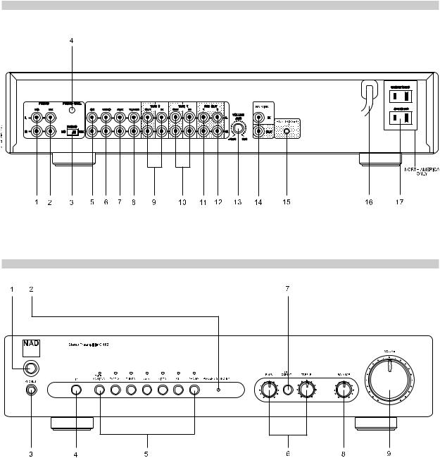
REAR PANEL CONNECTIONS
1. MC INPUT
Input for a Moving Coil phono cartridge. Connect the twin RCA lead from your turntable to this input if you are using a Moving Coil cartridge.
2. MM INPUT
Input for a Moving Magnet phono cartridge. Connect the twin RCA lead from your turntable to this input if you are using a Moving Magnet cartridge.
3. MC-MM SWITCH
Use this switch to select the phono input you are using.
4. PHONO GROUND CONNECTOR
Often, the twin RCA leads from turntables also includes a single wire earth lead. Use the NAD C 162 phono ground connector to connect this lead. Unscrew the terminal to expose the hole, which will accept the lead. After insertion, tighten the terminal to secure the lead.
5. CD INPUT
Input for a CD or other line-level signal source. Use a twin RCA-to-RCA lead to connect the CD player’s left and right ‘Audio Outputs’ to this input. The NAD C 162 only accepts analogue signals from your CD player.
6. VIDEO INPUT
Input for the audio signal from a stereo VCR (or stereo TV/Satellite/Cable receiver) or other line-level audio source. Using twin RCA-to-RCA leads, connect to the left and right ‘Audio Out’ of the unit to these inputs. Note: These are audio inputs only.
7. AUX INPUT
Input for additional line level input signals such as another CD player. Use a twin RCA-to-RCA lead to connect the auxiliary unit’s left and right ‘Audio Outputs’ to this input.
8. TUNER INPUT
Input for a Tuner or other line-level signal source. Use a twin RCA-to- RCA lead to connect the Tuner left and right ‘Audio Outputs’ to this input.
9. TAPE 2 IN, OUT
Connections for analogue recording and playback to an audio tape recorder of any type. Using twin RCA-to-RCA leads, connect to the left and right ‘Audio Output’ of the tape machine to the TAPE 2 IN sockets for playback and tape monitoring. Connect the left and right ‘Audio Input’ of the tape machine to the TAPE 2 OUT sockets for recording.
10. TAPE 1 IN, OUT
Connections for analogue recording and playback to a secondary audio tape recorder of any type. Using twin RCA-to-RCA leads, connect to the left and right ‘Audio Output’ of the tape machine to the TAPE 1 IN sockets for playback and tape monitoring. Connect the left and right ‘Audio Input’ of the tape machine to the TAPE 1OUT sockets for recording.
11. PRE OUT 1
The NAD C 162 allows for the connection multiple power amplifiers. If you are using a single stereo power amplifier, use the PRE OUT 1 sockets.
If you are using a pair of power amplifiers specifically for Bi-amping, use the sockets to connect the power amplifier with the lowest gain of the pair. Refer also to chapter “Bi-amping” for more information.
Use a twin RCA-to-RCA lead to connect to the left and right ‘Audio Input’ of the Power amp to the PRE OUT 1 sockets.
12. PRE OUT 2
The PRE OUT 2 sockets can be used to drive an additional power amplifier. The VOLUME PRE OUT 2 control (13) can be used to reduce the output level of the pre-amplifier to the power amplifier by up to - 12dB. With the VOLUME PRE OUT 2 control set to the maximum position (at the 0dB position), the output level will be identical to that of the PRE OUT 1 sockets.
If you are using a pair of power amplifiers specifically for Bi-amping, use the PRE OUT 2 sockets to connect the power amplifier with the highest gain of the pair. By adjusting the VOLUME PRE OUT 2 control (13) the volume level can be matched exactly to that of the power amplfier connected to the PRE OUT 1 sockets. Refer also to chapter “Bi-amping” for more information.
Use a twin RCA-to-RCA lead to connect to the left and right ‘Audio Input’ of the Power amp to the PRE OUT 1 sockets.
13. VOLUME PRE OUT 2
The VOLUME Pre Out 2 control allows for adjustment of the output level of the PRE OUT 2 sockets. The output level can be reduced by up to 12dB; when set to the maximum position (at the 0dB position), the output level will be identical to that of the PRE OUT 1 sockets. Refer also to chapter “Bi-amping” for more information.
NOTE
Always turn the pre-amplifier and associated power amplifiers off before connecting or disconnecting anything to the Pre-Out 1 & 2 sockets.
4

14. NAD LINK IN, OUT
The NAD-Link connector is used to pass commands from other units fitted with NAD-Link connectors. This allows centralised control of a complete system, and also allows some of the basic functions of other NAD components (such as a CD player or cassette-deck) also equipped with NAD-Link to be controlled with the pre-amplifier’s remote control. To function with such other units, connect the C 162’s NAD-Link Out to the NAD-Link In on the other unit. NAD-Link connectors can be daisychained, IN to OUT, so that a whole system can be controlled from the remote control facilities of one unit.
15. 12V TRIGGER OUT
The 12V trigger is activated automatically when switching the NAD C 162 from off or stand-by to on. Connect the 12V trigger to a power amplifier or AC outlet power strip equipped with a 12V trigger input for remote on/off switching of those devices. Use a cable terminated with a 3.5mm Mini-Jack connector at the pre-amplifier’s end for connection.
16. AC LINE CORD
Plug the AC power cord into a live AC wall socket. Make sure all connections have been made before connecting to mains.
17. SWITCHED AND UNSWITCHED POWER OUTLETS (AH VERSION ONLY)
The AC power cords of other stereo components, such as a CD player, may be plugged into these accessory outlets. Components plugged into the outlet marked “switched” will be switched on and off as the preamplifier is switched from stand-by or off to on and vice versa.
Mains power is always available on the outlet marked “unswitched” as long as the NAD C 162’s power cord is plugged into a live AC wall outlet. This outlet can be used for components which may require continuous supply of AC mains; some tuners require uninterrupted mains supply to retain preset memory, for instance.
NOTE
The total power consumption of any components connected to the AC outlets may not exceed 100 Watts. Never connect the mains lead of a power amplifier to either the Switched or Unswitched outlets of the NAD C 162.
QUICK START
1Connect a twin RCA lead to a power amplifier.
2Connect the desired sources to the relevant input sockets on the rear.
3Connect speakers to the power amplifier.
4Plug in the AC power cord.
5Press the POWER button to turn on the NAD C 162.
6Switch on the power amplifier
7Press the required input selector.
FRONT PANEL CONTROLS
1. POWER ON/OFF
Press the POWER button to switch the pre-amplifier to its ‘Stand-by’ mode. The Stand-by indicator (No. 2) over the power button will light up amber. On the front panel, press any of the input selector buttons to switch to pre-amplifier on. From the remote control, press the POWER ON button to switch the unit on. The Stand-by indicator will turn from amber to green to indicate it is switched on and ready for use.
NOTE
In Stand-by mode the C 162 uses very little power. However, it is recommended that you switch the unit totally off if it is not going to be used for more than a couple of days. Switch off completely by pressing the POWER button on the front panel (No. 1), all lights will extinguish.
2. POWER/STAND-BY
The indicator LED offers information on the status of the NAD C 162: Off: The unit is switched off totally.
Amber: The unit is in stand-by mode
Green: The unit is switched on and ready for use.
The LED will also flash when the pre-amplifier receives a remote control command from the supplied handset.
3. HEADPHONE SOCKET
A 1/4” stereo jack socket is supplied for headphone listening and will work with conventional headphones of any impedance. Inserting a headphone jack into this socket automatically switches off the output to the PRE OUT 1 & 2 sockets on the back panel. The volume, tone and balance controls are operative for headphone listening. Use a suitable adapter to connect headphones with other types of sockets, such as 3.5mm stereo ‘personal stereo’ jack plugs.
NOTE
Listening at high levels can damage your hearing.
4. INFRA-RED REMOTE CONTROL COMMAND RECEIVER
The infrared sensor, located behind this circular window, receives commands from the remote control. There must be a clear line-of-sight path from the remote control to this window; if that path is obstructed, the remote control may not work.
SVENSKA PORTUGUÊS ITALIANO ESPAÑOL NEDERLANDS DEUTSCH FRANÇAIS ENGLISH
5

SVENSKA PORTUGUÊS ITALIANO ESPAÑOL NEDERLANDS DEUTSCH FRANÇAIS ENGLISH
5. INPUT SELECTORS
These buttons select the active input to the NAD C 162 and the signal sent to the Tape outputs and the PRE OUT 1 & 2 sockets. The buttons on the remote control handset duplicate these buttons, with the exception of the tuner input; see below. An LED over each input selector button indicates which input has been selected.
PHONO selects the turntable connected to either the PHONO MM or MC sockets as the active input. Pressing the DISC button on the SR 5 remote selects the phono input.
CD Selects the CD (or other line-level source) connected to the CD sockets, as the active input.
VIDEO Selects the VCR (or stereo TV/Satellite/Cable pre-amplifier) connected to the VIDEO sockets, as the active input. Pressing the VIDEO 2 button on the SR 5 remote selects the VIDEO input.
AUX Selects a line-level source connected to the AUX sockets, as the active input.
TUNER Selects the tuner (or other line-level source) connected to the Tuner sockets, as the active input. The remote control handset has separate buttons for AM and FM; pressing either one will select the C 162’s tuner input.
TAPE 2 Selects Tape 2 as the active input.
TAPE 1 Monitor Selects the output from a tape recorder when playing back tapes or monitoring recordings being made through the Tape 1 sockets. Press the Tape 1 button once to select it and again to return to the normal input selection. Tape 1 is a tape Monitor function which does not override the current input selection. For example, if the CD is the active input when TAPE 1 is selected, then the CD signal will continue to be selected and sent to both the TAPE 2, and TAPE 1 OUTPUT sockets, but it is the sound from recorder connected to Tape 1 that will be heard. Apart from the amber LED to indicate Tape 1 is engaged, the green LED for the active input will also stay lit.
NOTE
The remote control handset with the C 162 supplied is of a universal NAD type, designed to operate several NAD models. Some buttons on this handset are inoperative as the functions aren’t supported by the C 162. The Video 2 and Video 3 input selector buttons on the remote control handset are inoperative in the case of the C 162.
6. BASS & TREBLE CONTROLS
The NAD C 162 is fitted with BASS and TREBLE tone controls to adjust the tonal balance of your system.
The 12 o’clock position is ‘flat’ with no boost or cut and a detent indicates this position. Rotate the control clockwise to increase the amount of Bass or Treble. Rotate the control anti-clockwise to decrease the amount of Bass or Treble. The Tone controls do not affect recordings made using the Tape outputs.
7. TONE DEFEAT
The TONE DEFEAT switch by-passes the tone control section of the NAD C 162. If the Tone Controls are not normally used and left in the 12 o’clock position, then it is advisable to switch out the Tone Control section altogether by using this switch. In the ‘out’ position, the Tone Control circuits are active, pushing the TONE DEFEAT switch ‘in’ bypasses the Tone Control section.
8. BALANCE
The BALANCE control adjusts the relative levels of the left and right speakers. The 12 o’clock position provides equal level to the left and right channels. A detent indicates this position.
Rotating the control clockwise moves the balance towards the right. Rotating the control anti-clockwise moves the balance to the left. The BALANCE control does not affect recordings made using the Tape outputs.
9. VOLUME
The VOLUME control adjusts the overall loudness of the signals being fed to the loudspeakers. It is motor driven and can be adjusted from the remote control handset. The VOLUME control does not affect recordings made using the Tape outputs.
On the remote control handset, press the MUTE Button to temporarily switch off the sound to the speakers and headphones. Mute mode is indicated by the active input LED flashing. Press MUTE again to restore sound. Mute does not affect recordings made using the Tape outputs but will affect the signal going to the Pre-amp output (Pre Out).
TO MAKE A RECORDING
When any source is selected, its signal is also fed directly to any tape machine connected to the TAPE 2 or TAPE 1 OUTPUTS for recording.
TAPE TO TAPE COPYING
You can copy between two tape machines connected to your NAD C 162. Put the source tape in the recorder connected to Tape 2 and the blank tape into the recorder connected to Tape 1. By selecting TAPE 2 Input you can now record from Tape 2 to Tape 1 and monitor the signal coming from the original tape.
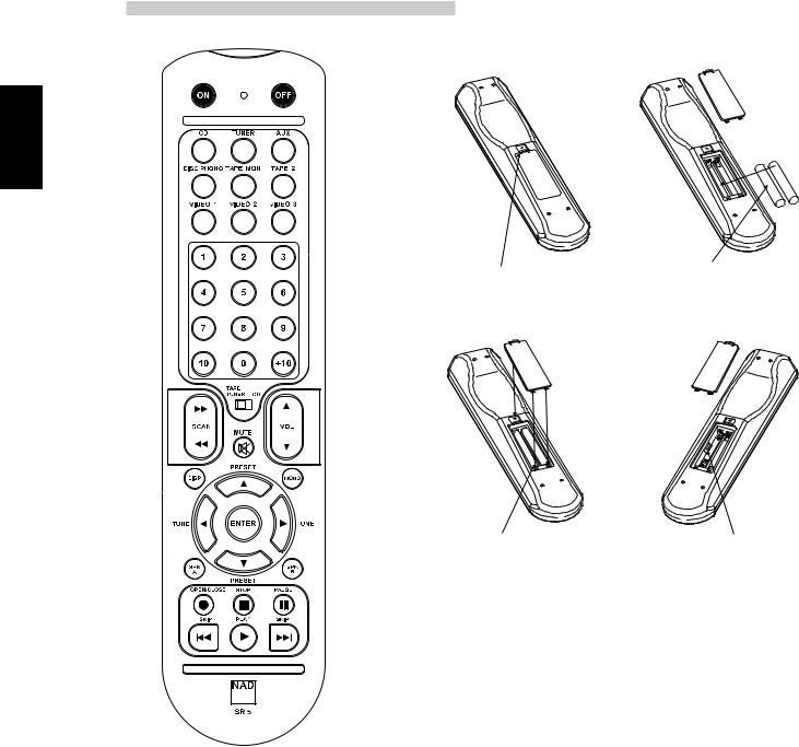
REMOTE CONTROL HANDSET
The Remote Control handset handles all the key functions of the NAD C 162 and has additional controls to remotely operate NAD Tuners, Cassette and CD machines. It will operate up to a distance of 16ft (5m). Alkaline batteries are recommended for maximum operating life. Two AAA (R 03) batteries should be fitted in the battery compartment at the rear of the Remote Control handset. When replacing batteries, check that they have been put in the right way round, as indicated on the base of the battery compartment.
Please refer to previous sections of the manual for a full description of individual functions.
POWER ON/OFF BUTTONS
Press ON to switch the unit on, the Standby indicator on the front panel will turn from amber to green within 2 seconds, meanwhile the CD indicator automatically flashes 4 times. The unit is now ready for use Press OFF to switch the unit to standby; the Stand-by indicator on the front panel will turn from green to amber.
The VIDEO 1, VIDEO 3, input selectors, and SPK A and SPK B buttons on the SR 5 remote control handset are inoperative when used with the C 162.
VIDEO 2
Selects the VCR (or stereo TV/Satellite/Cable pre-amplifier) connected to the VIDEO sockets, as the active input.
TUNER
Selects the Tuner input on the NAD C 162 and respectively the AM or FM waveband on a separate remote controllable NAD Tuner.
MUTE
Press the MUTE Button to temporarily switch off the sound to the speakers and headphones. Mute mode is indicated by the active input LED flashing. Press MUTE again to restore sound. Mute does not affect recordings made using the Tape outputs.
6

MASTER VOLUME
 or
or  respectively increases or decreases the Volume setting. The motorised Volume Control on the front panel will indicate the level set.
Other than the commands relating to the NAD C 162 amplifier itself, there are other buttons which will operate most NAD CD players and Cassette decks equipped with NAD Link:
TUNER CONTROL
(for use with NAD Tuner)
TUNE  or
or  scans respectively higher or lower station frequencies for both AM and FM.
PRESET  or
or  selects respectively higher or lower number station preset.
CD PLAYER CONTROL
(for use with NAD CD Player)
engages Pause.
engages Stop.
 engages Play or toggles between Play and Pause.

 or
or 

 engages Track skip; Press once to respectively go to the next track or to return to start of current or previous track.
CASSETTE DECK CONTROL
(For use with single (DECK B) or double transport (A and B) NAD Cassette Decks)
 or
or  engages Forward Play or Reverse Play.
stops Play
 engages Rewind.
  engages Fast Forward.
NOTE
Direct sunlight or very bright ambient lighting may affect the operating range and angle for the remote control handset.
TROUBLESHOOTING
BI-AMPING
Some loudspeakers have separate connection terminals for the LF (Low Frequency) and HF (High Frequency) sections of the speaker. This facility allows to “Bi-amp” these speakers, where a separate power amplifier is used for the LF and HF section, which may improve overall sound quality.
The NAD C 162 provides two sets of pre amplifier outputs (PRE OUT 1 & 2) to facilitate the connections for Bi-amping. Moreover, the level from PRE OUT 2 can be reduced in relation to PRE OUT 1 to accommodate power amplifiers with different gain (amplification factor).
To set up the C 162 with power amplifiers first decide which power amplifier has the highest gain. This is easily done by comparing the loudness level of the power amplifiers in an identical system (keep the volume control at the same level; use the same source and speakers). The amplifier that plays louder has the highest gain (note that this does not need to be the more powerful amplifier of the two).
Connect the amplifier with highest gain to the PRE OUT 2 (No. 12) sockets; the other power amplifier to the PRE OUT 1 (No. 11) sockets.
From the maximum level position (0dB), use the VOLUME PRE OUT 2 control (No. 13) to reduce the output level of PRE OUT 2 so that the volume level of both power amplifiers is exactly matched.
PROBLEM |
|
CAUSE |
|
SOLUTION |
|
|
|
|
|
NO SOUND |
• |
Power AC lead unplugged or power not |
• Check if AC lead is plugged in and power |
|
|
|
switched on |
|
switched on |
|
• Tape 1 Monitor selected |
• De-select Tape 1 Monitor mode |
||
|
• |
Mute on |
• |
Switch off Mute |
|
• Power amplifier is switched off |
• Switch power amplifier on |
||
|
• |
Headphones inserted |
• |
Unplug headphones |
|
|
|
|
|
NO SOUND ONE CHANNEL |
• |
Balance control not centered |
• |
Center Balance control |
|
• RCA lead to power amplifier not properly |
• Check leads and connections |
||
|
|
connected or damaged. |
• Check leads and connections |
|
|
• Input lead disconnected or damaged |
|||
|
|
|
|
|
PROBLEM ON PHONO INPUT ONLY |
• |
No signal |
• Check MM-MC switch set correctly |
|
|
• Hum on Phono input. |
• Check phono earth lead is connected |
||
|
• Weak or Distorted signal |
• Check the turntable is connected to the correct |
||
|
|
|
|
MM or MC phono input |
|
|
|
|
|
REMOTE CONTROL HANDSET NOT WORKING |
• |
Batteries flat, or incorrectly inserted |
• Check or replace batteries |
|
|
• IR transmitter or receiver windows obstructed |
• |
Remove obstruction |
|
|
• IR receiver in direct sun or very bright ambient |
• Place unit away from direct sun, reduce amount |
||
|
|
light |
|
of ambient light |
|
|
|
|
|
SVENSKA PORTUGUÊS ITALIANO ESPAÑOL NEDERLANDS DEUTSCH FRANÇAIS ENGLISH
7
REMOTE CONTROL
SVENSKA PORTUGUÊS ITALIANO ESPAÑOL NEDERLANDS DEUTSCH FRANÇAIS ENGLISH
PRESS IN AND LIFT TAB TO REMOVE BATTERY COVER OUT OF RECESS
REPLACE BATTERY COVER BY ALIGNING AND INSERTING THE TWO TABS INTO THE HOLES.
PRESS BATTERY COVER INTO PLACE UNTIL IT 'CLICKS' CLOSED
PLACE BATTERIES INTO OPENING. ENSURE THE CORRECT FITTING IS OBSERVED
DEV.1 & DEV.2
8
9
SVENSKA |
PORTUGUÊS |
ITALIANO |
ESPAÑOL |
NEDERLANDS |
DEUTSCH |
FRANÇAIS |
ENGLISH |
|
|
|
|
|
|
|
|

SVENSKA PORTUGUÊS ITALIANO ESPAÑOL NEDERLANDS DEUTSCH FRANÇAIS ENGLISH
NOTES CONCERNANT L’INSTALLATION
Posez votre NAD C 162 sur une surface stable, plane et horizontale. Évitez les rayons directs du soleil et les sources de chaleur et d’humidité. Assurez une ventilation adéquate. Ne posez pas cet appareil sur une surface molle (moquette, par exemple). Ne le placez pas dans un endroit confiné (sur une étagère de bibliothèque ou derrière des portes vitrées), où le flux d’air à travers les ouïes de ventilation risque d’être entravé. Vérifiez que l’appareil et les autres modules sont mis hors tension avant de réaliser des connexions quelconques.
Pour vous faciliter la tâche, les bornes RCA de votre NAD C 162 sont codées couleur. Rouge pour l’audio droite, blanc pour l’audio gauche, et jaune pour la Liaison-NAD.
N’utilisez que des câbles et des connecteurs de très bonne qualité, de manière à obtenir un branchement dont la fiabilité est parfaite et les performances optimales. Vérifiez que les câbles et les connecteurs ne présentent aucune détérioration, et que tous les connecteurs sont bien enfoncés jusqu’en butée.
Si l’appareil doit rester inutilisé pendant un certain temps, débranchez le cordon d’alimentation de la prise de secteur murale.
Si de l’eau pénètre à l’intérieur de votre NAD C 162, coupez l’alimentation de l’appareil et retirez la fiche de la prise secteur. Faites contrôler l’appareil par un technicien de service après-vente qualifié, avant toute tentative de remise en service.
Ne retirez pas le couvercle. A l’intérieur, il n’y a aucun élément sur lequel l’utilisateur peut intervenir.
Utilisez un chiffon doux sec et propre pour nettoyer l’appareil. Si nécessaire, humectez le chiffon avec un peu d’eau savonneuse. N’utilisez jamais une solution contenant du benzol ou un quelconque autre agent volatile.
BRANCHEMENTS SUR LE PANNEAU ARRIÈRE
1. ENTRÉE MC
Entrée pour tête de pick-up à Électrodynamique. Branchez le câble de votre platine tourne-disque à cette entrée si la platine est équipée d’une tête électrodynamique.
2. ENTRÉE MM
Entrée pour tête de pick-up Magnétique. Branchez le câble de votre platine tourne-disque à cette entrée si la platine est équipée d’une tête Magnétique.
3. SÉLECTEUR MC-MM
Utilisez ce sélecteur pour choisir l’entrée phono que vous utilisez.
4. PRISE DE TERRE PHONO
Les câbles RCA jumelés comportent souvent un conducteur de terre unique. Utilisez la prise de terre phono du NAD C 162 pour le branchement de ce conducteur. Dévissez la borne pour dégager le trou, dans lequel il vous suffira d’insérer le conducteur. Après avoir inséré le conducteur, serrez la borne pour le maintenir en place.
5. ENTRÉE CD
Entrée pour un lecteur CD ou pour toute autre source de signal de niveau ligne. Utilisez un câble jumelé RCA vers RCA pour relier les prises de sortie audio gauche et droit du lecteur CD à cette entrée. Le NAD C 162 n’accepte que les signaux analogiques de votre lecteur CD.
6. ENTRÉE VIDÉO
Entrée pour le signal audio provenant d’un magnétoscope stéréo (ou TV / Satellite / Câble stéréo) ou d’une autre source audio de niveau ligne. En utilisant les câbles jumelés RCA vers RCA, reliez les prises de “Sortie
Audio” gauche et droit de l’appareil à ces entrées. Nota : Il s’agit d’entrées audio uniquement.
7. ENTRÉE AUX
Entrée pour d’autres signaux de niveau ligne, comme un deuxième lecteur CD par exemple. Utilisez un câble jumelé RCA vers RCA pour relier les prises de “Sortie Audio” [Audio Outputs] gauche et droit de l’appareil audio auxiliaire à cette entrée.
8. ENTRÉE TUNER
Entrée pour un tuner ou pour toute autre source de signal de niveau ligne. Utilisez un câble jumelé RCA vers RCA pour relier les prises de “Sortie Audio” gauche et droit de l’appareil à cette entrée.
9.ENTRÉE / SORTIE “MAGNÉTOPHONE 2” [TAPE 1 IN, OUT]
Branchements pour enregistrement et lecture analogiques sur un magnétophone audio de type quelconque. En utilisant des câbles jumelés RCA vers RCA, reliez les prises de “Sortie Audio” gauche et droite du magnétophone aux prises d’ENTRÉE MAGNÉTOPHONE 2 [TAPE 2 IN] pour la lecture et le contrôle d’enregistrement des bandes. Reliez les prises d’Entrée Audio gauche et droite du magnétophone aux prises de SORTIE MAGNÉTOPHONE 2 [TAPE 2 OUT] pour l’enregistrement des bandes.
10.ENTRÉE / SORTIE “MAGNÉTOPHONE 1”
[TAPE 1 IN, OUT]
Branchements pour enregistrement et lecture analogiques sur un deuxième magnétophone audio de type quelconque. En utilisant des câbles jumelés RCA vers RCA, reliez les prises de “Sortie Audio” gauche et droite du magnétophone aux prises d’ENTRÉE MAGNÉTOPHONE 1 [TAPE 1 IN] pour la lecture et le contrôle d’enregistrement des bandes. Reliez les prises d’Entrée Audio gauche et droite du magnétophone aux prises de SORTIE MAGNÉTOPHONE 1 [TAPE 1 OUT] pour l’enregistrement des bandes.
11. SORTIE PRÉAMPLI 1 [PRE OUT 1]
Le NAD C 162 permet la connexion de plusieurs amplificateurs de puissance. Si vous utilisez un seul amplificateur de puissance, servezvous des prises de SORTIE PRÉAMPLI 1 [PRE OUT 1].
Si vous utilisez une paire d’amplificateurs de puissance spécifiquement conçus pour la fonction “Bi-amplificateurs”, utilisez les prises de “SORTIE PRÉAMPLI 2” pour brancher celui des deux amplificateurs dont le gain est le plus faible. Reportez-vous aussi au chapitre “Biamplificateurs” pour de plus amples informations.
Utilisez un câble jumelé RCA vers RCA pour relier les “Entrées Audio” gauche et droite de l’Amplificateur de Puissance aux prises de “SORTIE PRÉAMPLI 1” [PRE OUT 1].
10
12. SORTIE PRÉAMPLI 2 [PRE OUT 2]
Les prises de “SORTIE PRÉAMPLI 2” [PRE OUT 2] peuvent être utilisées pour piloter un deuxième amplificateur de puissance. La commande de VOLUME “SORTIE PRÉAMPLI 2” [PRE-OUT 2] (N° 13) permet de réduire le niveau de sortie du préamplificateur alimentant l’amplificateur de puissance de jusqu’à -12 dB. Lorsque la commande de VOLUME “SORTIE PRÉAMPLI 2” est réglée à sa position maximale (position 0 dB), le niveau de sortie est identique à celui des prises de “SORTIE PRÉAMPLI 1” [PRE OUT 1].
Si vous utilisez une paire d’amplificateurs de puissance spécifiquement conçus pour la fonction “Bi-amplificateurs”, utilisez les prises de “SORTIE PRÉAMPLI 2” pour brancher celui des deux amplificateurs dont le gain est le plus fort. En jouant sur la commande de VOLUME “SORTIE PRÉAMPLI 2” (N° 13), il est possible d’accorder avec précision le volume de sortie de cet amplificateur de puissance à celui de l’amplificateur connecté aux prises de “SORTIE PRÉAMPLI 1” (PRE OUT 1). Reportezvous aussi au chapitre “Bi-amplificateurs” pour de plus amples informations.
Utilisez un câble jumelé RCA vers RCA pour relier les “Entrées Audio” gauche et droite de l’Amplificateur de Puissance aux prises de “SORTIE PRÉAMPLI 1” [PRE OUT 1].
13. VOLUME SORTIE PRÉAMPLI 2 [VOLUME PRE OUT 2]
La commande de VOLUME “SORTIE PRÉAMPLI 2” [PRE OUT 2] permet de régler le niveau de sortie des PRISES DE “SORTIE PRÉAMPLI 2” [PRE OUT 2]. Il est possible de diminuer le niveau de sortie du préamplificateur alimentant l’amplificateur de puissance de jusqu’à 12 dB ; lorsque la commande est réglée à sa position maximale (position 0 dB), le niveau de sortie est identique à celui des prises de “SORTIE PRÉAMPLI 1” [PRE OUT 1]. Reportez-vous aussi au chapitre “Biamplificateurs” pour de plus amples informations.
NOTA
Mettez toujours le préamplificateur et les amplificateurs de puissance associés hors tension avant de brancher ou de débrancher quoique ce soit au niveau des prises sortie Préamplificateur 1 et 2 [Pre-Out 1 & 2].
14.“ENTRÉE / SORTIE LIAISON NAD” [NAD LINK IN, OUT]
Le connecteur de Liaison-NAD [NAD-Link] sert à relayer les commandes en provenance d’autres appareils équipés de connecteurs de LiaisonNAD. Cela permet de commander la chaîne entière depuis un point central, et assure aussi quelques fonctions de base pour d’autres composants NAD (tels que le tuner, le lecteur de CD ou le lecteur de cassettes) pourvus également d’une liaison NAD qui est commandée par la télécommande du préamplificateur. Pour assurer le relais vers d’autres appareils de ce type, reliez le connecteur de “Sortie Liaison-NAD” [NADLink OUT] du C 162 à l’Entrée NAD-Link de l’autre appareil. Il est possible de relier les connecteurs de Liaison-NAD en chaîne, ENTRÉE vers SORTIE, et donc de commander toute une chaîne d’appareils à l’aide de la télécommande d’un seul d’entre eux.
15.SORTIE “ASSERVISSEMENT 12 V” [12 V TRIGGER]
La sortie asservissement 12 V est activée automatiquement lorsque le NAD C 162 est mis en marche à partir du mode Veille ou Arrêt. Reliez l’asservissement 12 V à un amplificateur de puissance ou à un bandeau de prises secteur équipé d’un entrée d’asservissement 12 V, pour permettre la commutation de ces derniers. Utilisez un câble équipé d’un connecteur Mini-Jack de 3,5 mm du côté préamplificateur.
16. CORDON D’ALIMENTATION SECTEUR
Branchez le cordon secteur à une prise de courant murale en état de marche. Veillez à ce que tous les branchements aient été faits avant de brancher le cordon au secteur.
17. PRISES DE SECTEUR COMMUTÉES (VERSION AH UNIQUEMENT)
Les cordons secteur d’autres appareils pourront être branchés sur ces prises auxiliaires. Les modules branchés sur la sortie repérée “commutée” [“switched”] seront mis sous tension et hors tension lorsque vous mettez le préamplificateur en veille ou hors tension, respectivement.
La tension secteur est toujours disponible sur la sortie repérée “non commutée [“unswitched”], à condition que le cordon d’alimentation du NAD C 162 soit branché sur une prise de secteur murale en état de marche. Cette sortie permet d’alimenter les modules nécessitant une alimentation secteur permanente; certains tuners, par exemple, nécessitent une alimentation secteur ininterrompue afin de conserver les stations préréglées dans leur mémoire.
NOTA
La consommation totale de tous les modules connectés aux sorties secteur ne doit pas dépasser 100 Watts. Ne branchez jamais le câble d’alimentation d’un amplificateur de puissance aux sorties Commutées ou Non Commutées du NAD C 162.
MISE EN MARCHE RAPIDE
1Branchez un câble jumelé RCA à un amplificateur de puissance.
2Connectez les sources souhaitées aux prises d’entrées appropriées à l’arrière de l’appareil.
3Connectez les haut-parleurs à l’amplificateur de puissance.
4Branchez le cordon d’alimentation secteur.
5Appuyez sur le bouton-poussoir “ALIMENTATION” [POWER] pour mettre le NAD C 162 sous tension.
6Mettez l’amplificateur de puissance sous tension.
7Appuyez sur le sélecteur d’entrée correspondant à la source que vous souhaitez entendre.
COMMANDES SUR LA FACE PARLANTE
1. ALIMENTATION MARCHE/ARRÊT [POWER ON/OFF]
Appuyez sur le bouton d’ALIMENTATION [POWER] pour mettre le préamplificateur en mode “Veille”. Le témoin de Veille (N° 2) s’allume en orange au dessus du bouton Marche. Sur la face parlante, appuyez sur l’un des boutons de sélection des entrées pour mettre le préamplificateur en marche. Sur la télécommande, appuyez sur la touche ALIMENTATION MARCHE [POWER ON] pour mettre l’appareil sous tension. Le témoin de Veille passe de l’orange au vert pour indiquer que l’appareil est en marche et qu’il est prêt à fonctionner.
NOTA
Le C 162 ne consomme que très peu de courant en mode Veille. Toutefois, si l’appareil doit rester inutilisé pendant plusieurs jours, nous préconisons de le mettre hors tension. Pour mettre l’appareil hors tension, appuyez sur le bouton “Marche-Arrêt” [POWER] (N° 1) de la face parlante; tous les voyants s’éteindront.
2. LAMPE TÉMOIN DE VEILLE [STAND-BY]
La LED témoin donne des informations concernant l’état du NAD C 162: Inactif [Off] : L’appareil est complètement éteint.
Orange : L’appareil est en mode Veille
Vert : L’appareil est en marche, prêt à fonctionner.
La LED clignote lorsque le préamplificateur reçoit une commande en provenance du combiné de télécommande fourni avec l’appareil.
SVENSKA PORTUGUÊS ITALIANO ESPAÑOL NEDERLANDS DEUTSCH FRANÇAIS ENGLISH
11

SVENSKA PORTUGUÊS ITALIANO ESPAÑOL NEDERLANDS DEUTSCH FRANÇAIS ENGLISH
3. PRISE “CASQUE” [HEADPHONE]
Une prise stéréo pour fiche à jack de 1/4” est prévue pour l’écoute avec casque et convient aux casques conventionnels d’impédance quelconque. Le simple fait de brancher le casque sur cette prise coupe automatiquement le signal envoyé aux prises de SORTIE PRÉAMPLI 1 & 2 [PRE OUT 1 & 2] sur le panneau arrière. Les commandes de volume sonore, de tonalité et de balance agissent aussi sur l’écoute sur casque. Utilisez un adaptateur approprié pour brancher des casques équipés d’un autre type de connecteur, tel qu’un jack stéréophonique de 3,5 mm de type “baladeur stéréo”.
NOTA
L’écoute à des niveaux sonores élevés peut entraîner des dommages auditifs permanents.
4. RÉCEPTEUR INFRAROUGE DE TÉLÉCOMMANDES
Le capteur infrarouge, situé derrière cette fenêtre circulaire, reçoit les commandes de la télécommande. L’espace entre la télécommande et le récepteur doit être dégagé de tout obstacle, sinon la télécommande pourrait refuser de fonctionner.
5. SÉLECTEURS D’ENTRÉES
Ces boutons permettent de sélectionner l’entrée active du NAD C 162 ainsi que le signal envoyé aux sorties Magnétophone et aux prises de SORTIE PRÉAMPLI 1 & 2 [PRE OUT 1 & 2]. Les boutons sur la télécommande sont identiques à ces boutons, à l’exception de l’entrée tuner; voir ci-dessous. Une LED au dessus de chaque bouton de sélection d’entrée indique l’entrée actuellement active.
Le bouton PHONO sélectionne, comme entrée active, la platine tournedisques connecté aux prises PHONO MM ou MC. Le fait d’appuyer sur le bouton DISQUE [DISC] de la télécommande SR 5 sélectionne l’entrée phono. Le bouton CD sélectionne, comme entrée active, le lecteur CD (ou une source de niveau ligne) branchée aux prises CD.
Le bouton VIDÉO sélectionne, comme entrée active, le magnétoscope (ou un téléviseur / décodeur satellite / préamplificateur de télédistribution stéréo) connecté aux prises VIDÉO. Le fait d’appuyer sur le bouton VIDÉO 2 de la télécommande SR 5 sélectionne l’entrée VIDÉO. Le bouton AUX sélectionne, comme entrée active, une source de niveau ligne branchée aux prises AUX.
Le bouton TUNER Sélectionne, comme entrée active, le tuner (ou une source de niveau ligne) branché aux prises Tuner. Le combiné de télécommande est pourvu de boutons distincts AM et FM ; une impulsion sur l’un ou l’autre sélectionnera l’entrée Tuner du C 162.
Le bouton MAGNÉTOPHONE 2 [TAPE 2] sélectionne “Magnétophone 2” [Tape 2] comme l’entrée active.
Le bouton TAPE 1 Monitor sélectionne la sortie d’un magnétophone lors de la lecture de cassettes ou du suivi d’enregistrements à partir des prises “Magnétophone 1” [Tape 1]. Appuyez une fois sur le bouton “Magnétophone 1” [Tape 1] pour l’activer et une deuxième fois pour rétablir la sélection d’entrée normale. “Magnétophone 1” [Tape 1] est une fonction de suivi magnétophone qui n’annule pas la sélection d’entrée en cours. Par exemple, si le CD est l’entrée active lorsque TAPE 1 est sélectionné, le signal CD continue d’être sélectionné et est envoyé aussi bien aux prises de sortie TAPE 2 et TAPE 1, mais c’est le son du magnétophone relié à TAPE 1 qui sera entendu. En plus du voyant orange indiquant le fonctionnement du Magnétophone 1, le voyant vert de l’entrée active restera allumé il aussi.
NOTA
Le combiné de télécommande fourni avec le C 162 est de type NAD Universel ; il est conçu pour fonctionner avec plusieurs modèles d’appareils NAD. Certains boutons de ce combiné ne fonctionnent pas car les fonctions concernées ne sont pas supportées par le C 162. Les boutons de sélection d’entrée Vidéo 2 et Vidéo 3 sur la télécommande ne fonctionnent pas dans le cas du C 162.
6.COMMANDES DES “GRAVES” [BASS] ET DES “AIGUS” [TREBLE]
Le NAD C 162 est équipé de commandes de “GRAVES” [BASS] ET d’ “AIGUS” [TREBLE], qui permettent de régler la tonalité globale de votre chaîne. La position médiane (12 heures) correspond à une courbe plate, sans amplification ni atténuation; un léger déclic peut être ressenti dans le mouvement du bouton à cet endroit. Tournez le bouton en sens horaire pour amplifier les Graves ou les Aigus. Tournez le bouton en sens anti-horaire pour atténuer les Graves ou les Aigus. Les commandes de Tonalité n’affectent pas les enregistrements faits au moyen des Sorties “Magnétophone”.
7.“TONALITÉ NEUTRE” [TONE DEFEAT].
L’interrupteur de “TONALITÉ NEUTRE” [TONE DEFEAT] contourne la section de commande de la tonalité du NAD C 162. Si vous n’utilisez pas les commandes de tonalité, c’est à dire si elles restent toujours en position médiane (12 heures), il est conseillé de mettre les dispositifs de réglage de la tonalité complètement hors circuit grâce à ce boutoninterrupteur. Si le bouton n’est pas enfoncé, les circuits de tonalité sont actifs; le fait d’enfoncer le bouton “TONALITÉ NEUTRE” [TONE DEFEAT] contourne les circuits de réglage de la tonalité.
8. BALANCE
La commande de BALANCE règle les niveaux relatifs des haut-parleurs gauche et droit. La position médiane (12 heures) assure un niveau égal pour les voies gauche et droite. Un léger déclic peut être ressenti dans le mouvement du bouton à cet endroit.
En tournant le bouton en sens horaire, vous déportez l’équilibre vers la droite. En tournant le bouton en sens anti-horaire, vous déportez l’équilibre vers la gauche. La commande de BALANCE n’affecte pas les enregistrements faits au moyen des Sorties “Magnétophone”.
9. VOLUME
La commande de VOLUME sonore règle le volume global des signaux envoyés aux haut-parleurs. Elle est motorisée et peut être réglée à l’aide de la télécommande. La commande de VOLUME n’affecte pas les enregistrements faits au moyen des Sorties “Magnétophone”.
Sur la télécommande, appuyez sur le bouton “SILENCIEUX” [MUTE] pour couper provisoirement le son des haut-parleurs et du casque. Le mode Silencieux est indiqué par le clignotement de la LED de l’entrée active. Réappuyez sur “SILENCIEUX” [MUTE] pour rétablir le son. La commande Mute n’affecte pas les enregistrements faits au moyen des Sorties “Magnétophone” [TAPE] mais agit toutefois sur le signal allant vers la “Sortie de Préamplification” [Pre Out].
ENREGISTREMENT
Lorsqu’une source est sélectionnée, son signal est aussi envoyé directement à un quelconque magnétophone relié aux SORTIES “MAGNÉTOPHONE 2” ou “MAGNÉTOPHONE 1” [TAPE 2 ou TAPE 1] pour l’enregistrement.
“COPIER ENTRE CASSETTES” [TAPE TO TAPE]
Il est possible de réaliser des copies entre deux magnétophones connectés à votre NAD C 162. Mettez la bande source sur le magnétophone connecté à “Magnétophone 2” [Tape 2] et la bande vierge sur le magnétophone connecté à “Magnétophone 1” [Tape 1]. En sélectionnant l’Entrée “MAGNÉTOPHONE 2” [TAPE 2], il est possible d’enregistrer de “Magnétophone 2” à “Magnétophone 1”, et de contrôler le signal en provenance de la bande d’origine.
12

TÉLÉCOMMANDE
La Télécommande reproduit toutes les fonctions clés du NAD C 162, et comporte aussi des commandes supplémentaires permettant de télécommander les Tuners, les Magnétophones et les Lecteurs CD NAD. Elle fonctionne depuis une distance pouvant aller jusqu’à 5 mètres.
Il est conseillé d’utiliser des piles alcalines pour une longévité maximale. Le compartiment des piles, à l’arrière de la télécommande, est prévu pour deux piles de type (R 03) AAA. Lors du remplacement des piles, assurez-vous de leur bonne orientation conformément au dessin dans le fond du compartiment des piles.
Reportez-vous aux sections précédentes du manuel pour des descriptions détaillées des différentes fonctions.
BOUTONS ALIMENTATION MARCHE/ARRÊT [ON/OFF]
Appuyez sur le bouton MARCHE [ON] pour mettre l’appareil en marche; le témoin de Veille de la face parlante passe de l’orange au vert dans les deux secondes, alors que le témoin CD clignote automatiquement 4 fois. L’appareil est maintenant prêt à fonctionner.
Appuyez sur le bouton ARRÊT [OFF] pour mettre l’appareil en veille ; le témoin de Veille de la face parlante passe du vert à l’orange.
Les sélecteurs d’entrées VIDÉO 1, VIDÉO 3 et les boutons SPK A et SPK B de la télécommande SR 5 ne fonctionnent pas dans le cas du C 162.
VIDÉO 2
Ce bouton sélectionne, comme entrée active, le magnétoscope (ou un téléviseur / décodeur satellite / préamplificateur de télédistribution stéréo) connecté aux prises VIDÉO.
TUNER
Sélectionne l’entrée Tuner du NAD C 162, ainsi que la bande AM ou FM, suivant le cas, sur un Tuner NAD télécommandable.
SILENCIEUX [MUTE]
Appuyez sur le bouton SILENCIEUX [MUTE] pour couper provisoirement l’émission du son vers les haut-parleurs et le casque. Le mode Silencieux est indiqué par le clignotement de la LED de l’entrée active. Réappuyez sur SILENCIEUX [MUTE] pour rétablir le son. La commande Mute n’affecte pas les enregistrements faits au moyen des Sorties Magnétophone [Tape].
VOLUME GLOBAL [MASTER VOLUME]
Les boutons  or
or  permettent d’augmenter ou de diminuer le réglage du volume sonore, respectivement. La Commande de Volume motorisée sur la face parlante indiquera le niveau réglé.
En plus des commandes concernant l’amplificateur NAD C 162 luimême, d’autres boutons permettent de faire fonctionner la plupart des Lecteurs CD et Platines à Cassettes NAD équipés de la “Liaison NAD” [NAD Link]:
COMMANDE TUNER [TUNER CONTROL]
(à utiliser avec un Tuner NAD)
Les boutons d’ACCORDEMENT  et
et  [TUNE
[TUNE  &
&  ] permettent de balayer les stations en remontant ou en descendant, respectivement, les bandes AM et FM.
Les boutons de “PRÉRÉGLAGE  et
et  [PRESET
  &
&  ] sélectionnent le numéro de station présélectionnée suivante ou précédente, respectivement.
COMMANDE LECTEUR CD [CD PLAYER CONTROL]
(à utiliser avec un lecteur de CD NAD)
Les bouton |
|
|
|
|
active le mode Pause. |
|||||
|
|
|||||||||
Le bouton |
|
|
|
|
|
met l’appareil en mode Arrêt [Stop]. |
||||
|
|
|
||||||||
|
|
|
||||||||
Le bouton |
|
|
met l’appareil en mode Lecture [Play] ou bascule entre |
|||||||
Lecture et Pause. |
|
|
||||||||
Les boutons |
|
|
|
|
et |
|
activent le “Saut de Piste” [Track Skip] ; |
|||
|
|
|||||||||
|
|
|||||||||
appuyez une fois sur les boutons respectifs soit pour sauter à la piste suivante, soit pour retourner au début de la piste en cours ou précédente.
COMMANDES DE LA PLATINE A CASSETTES
(pour utilisation avec une platine à magnétophone simple (PLATINE B) ou avec une platine à double magnétophone (A et B).
(Platines lecteurs de cassettes NAD)
Les boutons |
et |
activent la Lecture en Avant [Forward Play] ou la |
|
Lecture en Arrière [Reverse Play]. |
|||
Le bouton |
|
arrête la Lecture. |
|
|
|||
|
|||
Le bouton |
active le Rembobinage Rapide [Rewind] |
||
Le bouton |
active l’Avance Rapide [Fast Forward]. |
||
NOTA
Les rayons de soleil directs ou un éclairage d’ambiance très lumineux peuvent avoir une incidence sur la distance et l’angle de fonctionnement de la télécommande.
BI-AMPLIFICATEURS
Certains haut-parleurs comportent des branchements distincts pour les sections BF (Basses Fréquences) et HF (Hautes Fréquences) de l’enceinte. Ce dispositif permet d’utiliser ces haut-parleurs en mode “BiAmplificateurs”, grâce auquel un amplificateur de puissance distinct est utilisé pour chaque section, BF et HF. Cela peut améliorer la qualité globale de la sonorité.
Le NAD C 162 comporte deux jeux de sorties préamplificateur “SORTIES PRÉAMPLI 1 & 2” [PRE OUT 1 & 2], afin de faciliter les branchements en mode bi-amplificateurs. En outre, il est possible de diminuer le niveau de la sortie de “SORTIE PRÉAMPLI 2” [PRE OUT 2] par rapport à celui de la sortie “SORTIE PRÉAMPLI 1” [PRE OUT 1], ce qui permet d’utiliser des amplificateurs de puissance dont le gain (facteur d’amplification) n’est pas identique.
Pour configurer le C 162 avec des amplificateurs de puissance, commencez par décider lequel des deux a le gain le plus élevé. Pour cela, il suffit tout simplement de comparer le volume sonore des deux amplificateurs de puissance sur une chaîne identique (la commande de volume sonore doit être maintenue au même niveau et il faut utiliser la même source et les mêmes haut-parleurs). L’amplificateur qui produit le son le plus fort a le gain le plus élevé (à noter qu’il ne s’agira pas forcément du plus puissant des deux amplificateurs).
Branchez l’amplificateur doté du gain le plus élevé aux prises “SORTIE PRÉAMPLI 2” [PRE OUT 2] (N° 12) ; branchez l’autre amplificateur de puissance aux prises “SORTIE PRÉAMPLI 1” [PRE OUT 1] (N° 11).
A partir de la position de niveau maximum (0 dB), réglez la commande de “VOLUME DE SORTIE PRÉAMPLI 2” [VOLUME PRE OUT 2] (N° 13) pour réduire le niveau de sortie de “SORTIE PRÉAMPLI 2” [PRE OUT 2] de manière à ce que le niveau sonore des deux amplificateurs de puissance soit parfaitement apparié.
SVENSKA PORTUGUÊS ITALIANO ESPAÑOL NEDERLANDS DEUTSCH FRANÇAIS ENGLISH
13

SVENSKA PORTUGUÊS ITALIANO ESPAÑOL NEDERLANDS DEUTSCH FRANÇAIS ENGLISH
|
DÉPANNAGE |
|
|
|
|
|
|
PROBLÈME |
|
CAUSE |
|
SOLUTION |
|
|
|
|
|
|
|
|
|
AUCUN SON |
• |
Câble secteur débranché, ou alimentation |
• Vérifiez si le cordon d’alimentation est branché |
|
|
|
|
|
coupée. |
|
et que la prise murale est sous tension |
|
|
|
• Tape 1 Monitor est sélectionné |
• Désélectionnez le Mode Tape 1 Monitor. |
|
||
|
|
• Fonction “Silencieux” [Mute] actif. |
• Désactivez la fonction “Silencieux” [Mute]. |
|
||
|
|
• Amplificateur de puissance pas sous tension. |
• Mettez l’amplificateur de puissance sous tension |
|
||
|
|
• |
Casque branché |
• |
Débranchez le casque |
|
|
|
|
|
|
|
|
|
PAS DE SON SUR UNE VOIE |
• |
La commande de Balance n’est pas au centre |
• Centrez la commande de Balance |
|
|
|
|
• Le câble RCA vers l’amplificateur de puissance |
• Vérifiez les câbles et les branchements. |
|
||
|
|
|
n’est pas correctement branché ou est détérioré. |
• Vérifiez les câbles et les branchements. |
|
|
|
|
• Le câble d’entrée est débranché ou détérioré. |
|
|||
|
|
|
|
|
|
|
|
PROBLÈME SUR l’ENTRÉE PHONO UNIQUEMENT |
• |
Aucun signal |
• Vérifiez que le sélecteur MM-MC est |
|
|
|
|
|
|
|
correctement configuré |
|
|
|
• Bourdonnement sur l’entrée Phono. |
• Vérifiez que le câble de masse phono est branché |
|
||
|
|
• Signal faible ou déformé |
• Vérifiez que la platine tourne-disque est reliée à |
|
||
|
|
|
l’entrée MM ou MC appropriée |
|
||
|
|
|
|
|
|
|
|
LA TÉLÉCOMMANDE NE FONCTIONNE PAS |
• |
Piles usées ou incorrectement insérées. |
• Vérifiez ou remplacez les piles. |
|
|
|
|
• Fenêtre d’émission ou de réception IR obstruée. |
• |
Retirez les obstructions. |
|
|
|
|
• Le récepteur IR se trouve en plein soleil ou sous |
• Éloignez l’appareil des rayons de soleil directs, |
|
||
|
|
|
un éclairage d’ambiance trop puissant |
|
réduisez la luminosité |
|
|
|
|
|
|
|
|
14

TÉLÉCOMMANDE
ENFONCEZ ET RELEVEZ LA LANGUETTE POUR RETIRER LE COUVERCLE DU COMPARTIMENT DES PILES
REMETTEZ EN PLACE LE COUVERCLE DU COMPARTIMENT DES PILES EN ALIGNENT LES DEUX LANGUETTES AVEC LES TROUS, PUIS EN LES Y INSÉRANT.
APPUYEZ SUR LE COUVERCLE DU COMPARTIMENT DES PILES POUR LE METTRE UN PLACE (VOUS RESSENTIREZ UN DÉCLIC)
INSÉREZ LES PILES DANS LE COMPARTIMENT. VÉRIFIEZ LA BONNE MISE EN PLACE
DEV.1 & DEV.2
SVENSKA PORTUGUÊS ITALIANO ESPAÑOL NEDERLANDS DEUTSCH FRANÇAIS ENGLISH
15

SVENSKA PORTUGUÊS ITALIANO ESPAÑOL NEDERLANDS DEUTSCH FRANÇAIS ENGLISH
HINWEISE ZUR AUFSTELLUNG
Der NAD C 162 sollte auf einer festen und ebenen Oberfläche aufgestellt werden. Vermeiden Sie es, das Gerät direktem Sonnenlicht oder Hitze und Feuchtigkeit auszusetzen. Achten Sie auf ausreichende Luftzirkulation. Stellen Sie das Gerät nicht auf weiche Oberflächen wie z. B. Teppiche, und nicht in abgeschlossene Bereiche wie Bücherregale oder -schränke, wenn diese keine ausreichende Luftzirkulation gewährleisten.
Schalten Sie das Gerät und andere Systemkomponenten aus, bevor Sie irgendwelche Verbindungen herstellen.
Zur besseren Übersicht sind die gummiisolierten Anschlußbuchsen am NAD C 162 farblich gekennzeichnet. Rot und weiß entsprechen dem linken bzw. rechten Audiokanal, und gelb wird für die Systemsteuerung (NAD Link) verwendet.
Verwenden Sie für den Anschluß nur hochwertige Leitungen und Buchsen, damit der NAD C 162 immer optimal und zuverlässig arbeitet. Achten Sie außerdem darauf, daß Anschlußleitungen und Buchsen frei von Beschädigungen sind und alle Steckverbindungen fest sitzen.
Ziehen Sie den Netzstecker aus der Steckdose, wenn das Gerät längere Zeit nicht benutzt wird.
Sollte Wasser in den NAD C 162 eindringen, schalten Sie das Gerät aus und ziehen den Netzstecker aus der Steckdose. Lassen Sie das Gerät von einem qualifizierten Servicetechniker untersuchen, bevor Sie es wieder verwenden.
Nehmen Sie nicht den Gehäusedeckel ab. Im Geräteinnern befinden sich keine vom Benutzer reparierbaren Teile.
Säubern Sie das Gerät mit einem trockenen weichen Tuch. Befeuchten Sie das Tuch bei Bedarf leicht mit etwas Seifenwasser. Verwenden Sie keine Lösungsmittel, die Benzol oder andere Verdunstungsmittel enthalten.
RÜCKWANDANSCHLÜSSE
1. MC-EINGANG (MC INPUT)
Eingang für ein MC-Tonabnehmersystem (Moving Coil). Verbinden Sie Ihren Plattenspieler über ein zweifaches, gummiisoliertes Anschlußkabel mit diesem Eingang, wenn Sie ein MC-Tonabnehmersystem verwenden.
2. MM-EINGANG (MM INPUT)
Eingang für ein MM-Tonabnehmersystem (Moving Magnet). Verbinden Sie Ihren Plattenspieler über ein zweifaches, gummiisoliertes Anschlußkabel mit diesem Eingang, wenn Sie ein MMTonabnehmersystem verwenden.
3. MC-MM-UMSCHALTER (MC-MM SWITCH)
Stellen Sie mit diesem Schalter den verwendeten Phono-Eingang ein.
4.PHONO-ERDUNGSANSCHLUß (PHONO GROUND CONNECTOR)
Zweifache, gummiisolierte Anschlußkabel für Plattenspieler haben oft auch eine separate Leitung für den Erdungsanschluß. Schließen Sie diese Leitung am Phono-Erdungsanschluß des NAD C 162 an. Lösen Sie dazu die Anschlußklemme so weit, bis das Loch zur Aufnahme der Leitung freiliegt. Führen Sie die Leitung ein und drehen die Anschlußklemme zur Sicherung der Leitung fest.
5.CD-PLAYER-EINGANG (CD INPUT)
Eingang für einen CD-Player oder eine andere Linepegel-Signalquelle. Verbinden Sie diesen Eingang mit dem linken und rechten CD-Player- Audioausgang über ein zweifaches, gummiisoliertes Anschlußkabel. Der NAD C 162 verarbeitet von einem CD-Player nur analoge Signale.
6. VIDEOEINGANG (VIDEO INPUT)
Eingang für das Audiosignal eines Stereo-Videorekorders (oder Stereo- TV-/Satelliten-/Kabelempfängers) oder einer anderen LinepegelSignalquelle. Verbinden Sie den linken und rechten Audioausgang eines Videogerätes mit zweifachen, gummiisolierten Anschlußkabeln mit diesen Eingängen. Hinweis: Nur Audioeingänge.
7. ZUSATZEINGANG (AUX INPUT)
Eingang für zusätzliche Linepegel-Signale wie z. B. eine zweiter CDPlayer. Verbinden Sie diesen Eingang mit dem linken und rechten Audioausgang des Zusatzgerätes über ein zweifaches, gummiisoliertes Anschlußkabel.
8. TUNER-EINGANG (TUNER INPUT)
Eingang für einen Tuner oder eine andere Linepegel-Signalquelle. Verbinden Sie diesen Eingang mit dem linken und rechten Audioausgang des Tuners über ein zweifaches, gummiisoliertes Anschlußkabel.
9. EIN-/AUSGANG TONBAND 2 (TAPE 1 IN, OUT)
Anschlüsse für analoge Aufzeichnung und Wiedergabe eines beliebigen Tonbandgerätes. Verbinden Sie zur Wiedergabe und Bandüberwachung den linken und rechten Audioausgang der Bandmaschine mit einem zweifachen, gummiisolierten Anschlußkabel mit den Anschlüssen TAPE 2 IN (Tonbandeingang 1). Für die Aufnahme verbinden Sie den linken und rechten Audioeingang der Bandmaschine mit den Buchsen TAPE 2 OUT (Tonbandausgang 1).
10.EIN-/AUSGANG TONBAND 1 (TAPE 1 IN, OUT)
Anschlüsse für analoge Aufzeichnung und Wiedergabe eines beliebigen zweiten Tonbandgerätes. Verbinden Sie zur Wiedergabe und Bandüberwachung den linken und rechten Audioausgang der Bandmaschine mit einem zweifachen, gummiisolierten Anschlußkabel mit den Anschlüssen TAPE 1 IN (Tonbandeingang 1). Für die Aufnahme verbinden Sie den linken und rechten Audioeingang der Bandmaschine mit den Buchsen “TAPE OUT 1” (Tonbandausgang 1).
11.VORVERSTÄRKERAUSGANG 1 (PRE-OUT 2)
Der NAD C 162 ermöglicht den Anschluß mehrerer Leistungsverstärker. Wenn Sie nur einen Stereo-Leistungsverstärker verwenden, nehmen Sie die Anschlüsse “PRE OUT 1”. Bei einem Leistungsverstärker-Paar, das speziell für Bi-Amping benutzt wird, schließen Sie an diesen Buchsen den Leistungsverstärker mit der niedrigeren Verstärkung an. Weitere Informationen dazu finden Sie im Kapitel „Bi-Amping”.
Verbinden Sie die Buchsen “PRE OUT2” mit dem linken und rechten Audioeingang des Leistungsverstärkers über ein zweifaches, gummiisoliertes Anschlußkabel.
12. VORVERSTÄRKERAUSGANG 2 (PRE-OUT 2)
Über die Buchsen PRE OUT 2 kann ein weiterer Leistungsverstärker angesteuert werden. Mit dem Einsteller VOLUME PRE OUT 2 (13) kann der Vorverstärker-Ausgangspegel zum Leistungsverstärker bis auf -12 dB reduziert werden. Ist dieser Einsteller in Maximalposition (Stellung 0 dB), ist der Ausgangspegel mit dem von “PRE OUT 1” identisch.
Verwenden Sie ein Leistungsverstärker-Paar speziell für Bi-Amping, schließen Sie den Leistungsverstärker mit der höheren Verstärkung an die Buchsen “PRE OUT 2” an. Mit dem Einsteller “VOLUME PRE OUT 2” (13) kann der Lautstärkepegel exakt mit dem des an den Buchsen “PRE OUT 1” angeschlossenen Leistungsverstärkers abgestimmt werden. Weitere Informationen dazu finden Sie im Kapitel „Bi-Amping”.
Verbinden Sie die Buchsen “PRE OUT2” mit dem linken und rechten Audioeingang des Leistungsverstärkers über ein zweifaches, gummiisoliertes Anschlußkabel.
16
 Loading...