

Page 1

be certain.
MTS Models FlexTest® IIm/GT/SE Controller Hardware
Service Information for Controllers Using Series 793 Software:
- Hardware Descriptions
- Specifications
- Installation
- Cabling
100-147-133 G
Page 2

Copyright information © 2006, 2007, 2008, 2009 MTS Systems Corporation. All rights reserved.
Trademark information MTS, FlexTest, Temposonics, and TestWare are registered trademarks of MTS
Systems Corporation; MPT, Station Builder, and Station Manager are trademarks
of MTS Systems Corporation within the United States. These trademarks may be
protected in other countries.
Microsoft and Windows are registered trademarks of Microsoft Corporation. All
other trademarks or service marks are property of their respective owners
Publication information
MANUAL PART NUMBER PUBLICATION DATE MTS 793 SOFTWARE RELEASE
100-147-133 A June 2006 Version 4.0A or later
100-147-133 B October 2006 Version 4.0B or later
100-147-133 C December 2006 Version 4.0B or later
100-147-133 D November 2007 Version 5.0B or later
100-147-133 E January 2008 Version 5.0B or later
100-147-133 F September 2008 Version 5.1A or later
100-147-133 G August 2009 Version 5.2A or later
2
Models FlexTest® IIm/GT/SE Controller Hardware
Page 3

Contents
Technical Support 9
How to Get Technical Support 9
Before You Contact MTS 10
If You Contact MTS by Phone 11
Problem Submittal Form in MTS Manuals 12
Preface 15
Before You Begin 15
Conventions 16
Documentation Conventions 16
Chapter 1 Introduction 19
FlexTest GT Controllers 20
Model 493.10 Chassis 20
Hydraulic Control 22
Interlocks 22
Specifications 23
FlexTest SE Controllers 24
Model 493.02 Chassis 26
Hydraulic Control 26
Interlocks 26
Specifications 27
FlexTest IIm Controllers 28
Model 497.01 Analog Chassis 30
Model 497.05 Hydraulic Control Panel 31
Model 498.22 Chassis with Test Processor (FTIIm) 32
Specifications 33
Models FlexTest® IIm/GT/SE Controller Hardware Contents
3
Page 4

Chapter 2 Installation 37
Installing the Model 493.10 Chassis (FTGT) 37
Connecting Electrical Power 38
Installing the Plug-in Modules 42
VMEbus Modules 43
Installing the Transition Panels 47
Installing the 493.02 Chassis (FlexTest SE) 49
Installing the Plug-in Modules 49
VMEbus Modules 50
Chassis Installation Options 51
Connecting Electrical Power 53
Installing the Handle Kit 58
Installing 497/498 Electronics (FTIIm) 61
Connecting the Console and Chassis Power 61
How To Connect the Chassis Power Cables 61
How To Cable the Analog Chassis to the Hydraulic Control Panel 62
Grounding the Console and Chassis 62
Model 497.01 Analog Chassis 63
About Analog Chassis Slots 63
Analog Chassis Plug-in Modules 64
How to Install or Remove a Plug-in Module 65
Analog Chassis Transition Modules 66
How To Install a Transition Module 66
Transition Module Connectors 67
Adding an Analog Chassis to Your Console 69
Model 497.05 Hydraulic Control Panel 71
Test Processor Plug-in Modules 72
Test Processor Transition Modules 74
UPS Systems 76
UPS Systems for FlexTest 60, 100, 200, and GT Controllers 76
UPS Systems for FlexTest 40 and FlexTest SE Servocontrollers 77
Specifications–UPS Systems Used with MTS Controllers 78
UPS Connections for the Model 493.73 HPU Board (FT60, FT100, FT200, FTGT) 79
UPS Connections for the Model 493.42 System board (FlexTest SE ) 80
4
Contents
Models FlexTest® IIm/GT/SE Controller Hardware
Page 5

Chapter 3 FlexTest GT Controller Connections 81
CE EMC Compliant Cabling 83
Typical Cabling 84
Cable Part Numbers 85
Model 493.40 I/O Carrier Connections 87
Sensor Connections 88
Model 493.21B (DUC B) Jumpers 92
Digital Universal Conditioner (DUC BC) Switches 94
Full-Range Digital Universal Conditioner (FRDUC) Jumpers 97
Sensor Cables 100
Sensor Cable Specifications 100
Sensor Cable Part Numbers 101
Shunt Calibration/Bridge Completion Resistor Installation 103
I/O Carrier Module 103
Transducer Identification Modules 106
Valve Connections 108
Multiple Universal Driver Connections 112
Analog I/O Connections 114
Accelerometer Connections 119
Encoder Connections 121
Remote Setpoint Adjust Connections 123
ADDA II Connections 124
Emergency Stop Connections 129
J25 Hydraulic Power Unit Connection 131
Station Connections 134
J28 Hydraulic Service Manifold Connector 134
J29 Load Unit 136
J43 Interlock 137
J44 Run/Stop 138
J49 Auxiliary Power 140
Digital I/O Connections 141
Workstation Connection 145
Remote Station Controller Connection 147
Service Connections 149
Models FlexTest® IIm/GT/SE Controller Hardware Contents
5
Page 6

Cabling and Programming Series 407 Controllers 151
How to Provide Program to a Series 407 Controller 151
Connecting Interlock Signals to 407 Controllers 156
Sending and Receiving Signals to a Model 407 Controller 162
Connecting Interlock Signals to 458 Controllers 164
Eurotherm Temperature Controller Connection 165
Miscellaneous Conditioner Output Connections 167
Cabling for External Command Inputs 168
How to Enable and Run External Command Inputs 168
Cabling and Using External Readout Devices 169
How to Send Signals to External Readout Devices 171
Multi-Box I/O Module 172
J8 Interlock IN 172
J9 Interlock OUT 173
J51 Box In 174
J52 Box Out 175
Chapter 4 FlexTest IIm Controller Connections 177
6
Workstation Connection 178
Sensor and Valve Connections 179
ADDA Module Connections 183
ADDA II Connections 184
Hydraulic Connections 189
HPU Connections 190
HSM Connections 191
Interlock Connections 192
Interlock Jumper Plugs 193
Serial Communications 195
Digital I/O Connections 196
Encoder/Temposonics Connections 200
Remote Station Controller (RSC) Connections 203
Cabling and Programming External Controllers 204
How to Program an External Controller 204
Programming Eurotherm Temperature Controllers 209
Contents
Models FlexTest® IIm/GT/SE Controller Hardware
Page 7

Cabling for External Command Inputs 210
How to Enable and Run External Command Inputs 210
Cabling and Using External Readout Devices 213
How to Send Signals to External Readout Devices 213
Cable Part Numbers 216
Chapter 5 FlexTest SE Controller Connections 217
Stand-alone Cabling Overview 218
Automated Cabling Overview 219
Multiple Controller Connections 220
Cable Part Numbers 223
Model 493.40 I/O Carrier Connections 225
Sensor Connections 226
Valve Connections 226
Analog I/O Connections 226
Encoder Connections 228
Workstation Connection 229
Service Connection 229
Model 493.42 System I/O Connections 230
J25 Hydraulic Power Unit Connection 230
J28 Hydraulic Service Manifold Connector 231
J29 Emergency Stop Connections 232
J43 Interlock 233
J49 Auxiliary Power 234
CJ51 Box In 234
J52 Box Out 235
J54 Digital Inputs 236
J55 Digital Outputs 237
Eurotherm Temperature Controller Connection 239
Models FlexTest® IIm/GT/SE Controller Hardware Contents
7
Page 8

Appendix A Hydraulic Configurations 243
Model 493.02 Chassis Multiple Controller Interconnections 246
Independent HSM (no HPU) 246
Independent HSM (shared HPU) 247
Shared HSM (with HPU) 247
Shared HSM (no HPU) 248
Independent HSM with HPU (First On-Last Off) 249
Appendix B Model 493.07 Converter Box 251
Appendix C Chassis Maintenance 253
Appendix D Optional Station Configurations 255
6-Station Configuration 255
8-Station Configuration 256
8
Contents
Index 257
Models FlexTest® IIm/GT/SE Controller Hardware
Page 9

Technical Support
How to Get Technical Support
How to Get Technical Support
Start with your
manuals
Technical support
methods
The manuals supplied by MTS provide most of the information you need to use
and maintain your equipment. If your equipment includes software, look for
online help and README files that contain additional product information.
If you cannot find answers to your technical questions from these sources, you
can use the Internet, e-mail, telephone, or fax to contact MTS for assistance.
MTS provides a full range of support services after your system is installed. If
you have any questions about a system or product, contact Technical Support in
one of the following ways.
www.mts.com The web site provides access to our technical support staff by means of an
onlineform:
www.mts.com > Contact MTS > Service & Technical Support button
E-mail tech.support@mts.com
Telephone MTS Call Center 800-328-2255
Weekdays 7:00 A.M. to 5:00 P.M., Central Time
Fax 952-937-4515
Please include “Technical Support” in the subject line.
Outside the U.S. For technical support outside the United States, contact your local sales and
service office. For a list of worldwide sales and service locations and contact
information, use the Global MTS link at the MTS web site:
www.mts.com > Global MTS > (choose your region in the right-hand
column) > (choose the location closest to you)
Models FlexTest® IIm/GT/SE Controller Hardware Technical Support
9
Page 10

Before You Contact MTS
Before You Contact MTS
MTS can help you more efficiently if you have the following information
available when you contact us for support.
Know your site
number and system
number
Know information from
prior technical
The site number contains your company number and identifies your equipment
type (such as material testing or simulation). The number is typically written on a
label on your equipment before the system leaves MTS. If you do not know your
MTS site number, contact your sales engineer.
Example site number: 571167
When you have more than one MTS system, the system job number identifies
your system. You can find your job number in your order paperwork.
Example system number: US1.42460
If you have contacted MTS about this problem before, we can recall your file
based on the:
assistance
• MTS notification number
• Name of the person who helped you
Identify the problem Describe the problem and know the answers to the following questions:
• How long and how often has the problem occurred?
• Can you reproduce the problem?
• Were any hardware or software changes made to the system before the
problem started?
Technical Support
10
• What are the equipment model numbers?
• What is the controller model (if applicable)?
• What is the system configuration?
Models FlexTest® IIm/GT/SE Controller Hardware
Page 11

If You Contact MTS by Phone
Know relevant
computer information
Know relevant
software information
For a computer problem, have the following information available:
• Manufacturer’s name and model number
• Operating software type and service patch information
• Amount of system memory
• Amount of free space on the hard drive where the application resides
• Current status of hard-drive fragmentation
• Connection status to a corporate network
For software application problems, have the following information available:
• The software application’s name, version number, build number, and (if
available) software patch number. This information can typically be found
in the About selection in the Help menu.
• The names of other applications on your computer, such as:
– Anti-virus software
– Screen savers
– Keyboard enhancers
– Print spoolers
– Messaging applications
If You Contact MTS by Phone
A Call Center agent registers your call before connecting you with a technical
support specialist. The agent asks you for your:
• Site number
• Name
• Company name
• Company address
• Phone number where you can be reached
If your issue has a notification number, please provide that number. A new issue
will be assigned a unique notification number.
Models FlexTest® IIm/GT/SE Controller Hardware Technical Support
11
Page 12

Problem Submittal Form in MTS Manuals
Identify system type To enable the Call Center agent to connect you with the most qualified technical
support specialist available, identify your system as one of the following types:
• Electromechanical material test system
• Hydromechanical material test system
• Vehicle test system
• Vehicle component test system
• Aero test system
Be prepared to
Prepare to perform troubleshooting while on the phone:
troubleshoot
• Call from a telephone close to the system so that you can implement
suggestions made over the phone.
• Have the original operating and application software media available.
• If you are not familiar with all aspects of the equipment operation, have an
experienced user nearby to assist you.
Write down relevant
In case Technical Support must call you:
information
• Verify the notification number.
• Record the name of the person who helped you.
• Write down any specific instructions.
After you call MTS logs and tracks all calls to ensure that you receive assistance for your
problem or request. If you have questions about the status of your problem or
have additional information to report, please contact Technical Support again and
provide your original notification number.
Problem Submittal Form in MTS Manuals
Use the Problem Submittal Form to communicate problems with your software,
hardware, manuals, or service that are not resolved to your satisfaction through
the technical support process. The form includes check boxes that allow you to
indicate the urgency of your problem and your expectation of an acceptable
response time. We guarantee a timely response—your feedback is important to
us.
Technical Support
12
Models FlexTest® IIm/GT/SE Controller Hardware
Page 13

Problem Submittal Form in MTS Manuals
Access the Problem Submittal Form:
• In the back of many MTS manuals (postage paid form to be mailed to MTS)
• www.mts.com > Contact Us > Problem Submittal Form button (electronic
form to be e-mailed to MTS)
Models FlexTest® IIm/GT/SE Controller Hardware Technical Support
13
Page 14

Problem Submittal Form in MTS Manuals
Technical Support
14
Models FlexTest® IIm/GT/SE Controller Hardware
Page 15

Before You Begin
Preface
Before You Begin
Safety first! Before you use your MTS product or system, read and understand the Safety
manual and any other safety information provided with your system. Improper
installation, operation, or maintenance can result in hazardous conditions that can
cause severe personal injury or death, or damage to your equipment and
specimen. Again, read and understand the safety information provided with your
system before you continue. It is very important that you remain aware of
hazards that apply to your system.
Other MTS manuals In addition to this manual, you may receive additional manuals in paper or
electronic form.
You may also receive an MTS System Documentation CD. It contains an
electronic copy of the manuals that pertain to your test system, such as:
• Hydraulic and mechanical component manuals
• Assembly drawings
• Parts lists
• Operation manual
• Preventive maintenance manual
Controller and application software manuals are typically included on the
software CD distribution disc(s).
Models FlexTest® IIm/GT/SE Controller Hardware Preface
15
Page 16

Documentation Conventions
DANGER
WARNING
CAUTION
Conventions
Documentation Conventions
The following paragraphs describe some of the conventions that are used in your
MTS manuals.
Hazard conventions Hazard notices may be embedded in this manual. These notices contain safety
information that is specific to the activity to be performed. Hazard notices
immediately precede the step or procedure that may lead to an associated hazard.
Read all hazard notices carefully and follow all directions and recommendations.
Three different levels of hazard notices may appear in your manuals. Following
are examples of all three levels.
Note For general safety information, see the safety information provided with
your system.
Danger notices indicate the presence of a hazard with a high level of risk which,
if ignored, will result in death, severe personal injury, or substantial property
damage.
16
Warning notices indicate the presence of a hazard with a medium level of risk
which, if ignored, can result in death, severe personal injury, or substantial
property damage.
Caution notices indicate the presence of a hazard with a low level of risk which,
if ignored, could cause moderate or minor personal injury or equipment damage,
or could endanger test integrity.
Notes Notes provide additional information about operating your system or highlight
easily overlooked items. For example:
Note Resources that are put back on the hardware lists show up at the end of
the list.
Special terms The first occurrence of special terms is shown in italics.
Preface
Models FlexTest® IIm/GT/SE Controller Hardware
Page 17

Documentation Conventions
Illustrations Illustrations appear in this manual to clarify text. They are examples only and do
not necessarily represent your actual system configuration, test application, or
software.
Electronic manual
conventions
This manual is available as an electronic document in the Portable Document
File (PDF) format. It can be viewed on any computer that has Adobe Acrobat
Reader installed.
Hypertext links The electronic document has many hypertext links displayed in a blue font. All
blue words in the body text, along with all contents entries and index page
numbers, are hypertext links. When you click a hypertext link, the application
jumps to the corresponding topic.
Models FlexTest® IIm/GT/SE Controller Hardware Preface
17
Page 18

Documentation Conventions
18
Preface
Models FlexTest® IIm/GT/SE Controller Hardware
Page 19

Chapter 1
Introduction
Contents FlexTest GT Controllers 20
This manual contains installation, cabling, jumpering, and hardware interfacing
information for MTS 793 Controllers.
This chapter describes the hardware components and specifications of FlexTest
GT, FlexTest SE, and FlexTest IIm Controllers.
Model 493.10 Chassis 20
Hydraulic Control 22
Interlocks 22
Specifications 23
FlexTest SE Controllers 24
Model 493.02 Chassis 26
Hydraulic Control 26
Interlocks 26
Specifications 27
FlexTest IIm Controllers 28
Model 497.01 Analog Chassis 30
Model 497.05 Hydraulic Control Panel 31
Model 498.22 Chassis with Test Processor (FTIIm) 32
Specifications 33
Models FlexTest® IIm/GT/SE Controller Hardware Introduction
19
Page 20
Model 493.10 Chassis
BFL
CPU
PMC
ABT
RST
m
498.98-2
Power PC
J6 I/O
J7 I/O
493.40
I/O Carrier
J3 Service
Shunt Cal
J4 I/O
J5 I/O
m
CLOCK OUT
EVENT OUT
J3 IN
J6 STATION
J7 SERIAL
EVENT IN
J4 OUT
J5 DEBUG
+12V
m
498.71B
GRES III
J6 I/O
J7 I/O
493.40
I/O Carrier
J3 Service
Shunt Cal
J4 I/O
J5 I/O
m
J6 I/O
J7 I/O
493.40
I/O Carrier
J3 Service
Shunt Cal
J4 I/O
J5 I/O
m
J6 I/O
J7 I/O
493.40
I/O Carrier
J3 Service
Shunt Cal
J4 I/O
J5 I/O
m
12345678910
MTS Sysrtems Corp
14000 Technologyu Dr.
Eden Prairie, MN 555344-2290 USA
Assy No:
Model: S/N
l
J50D
J7 SERIAL
J50C
J50B
J50A
m
493.71
Serial
Interface
J3 IN
J4 OUT
+12V
m
493.72
Digital I/O
J44BJ44A Run/Stop
J49BJ49A Aux Pwr
J29BJ29A Load Unit
m
J43BJ43A Intlk
J28A HSM
J28B HSM
493.74
HSM
SERVICE
J23
E-STOP OUT
J24
E-STOP IN
J25 HPS
J54
SYS I/O
m
493.73
HPU
Ch 1
Ch 2
Ch 3
Ch 4
Ch 5
Ch 6
m
J11
(Ch 1-4)
J12
(Ch 5-6)
493.75
Analog In
Ch 1
Ch 2
Ch 3
Ch 4
Ch 5
Ch 6
m
J11
(Ch 1-4)
J12
(Ch 5-6)
493.76
Analog Out
J44BJ44A Run/Stop
J49BJ49A Aux Pwr
J29BJ29A Load Unit
m
J43BJ43A Intlk
J28A HSM
J28B HSM
493.74
HSM
PowerOKOver
Temp
J39 Power Monitor
Power
l
12345678910 BA
Front Panel
(with VMEbus Modules)
Rear Panel
(with Transition Modules)
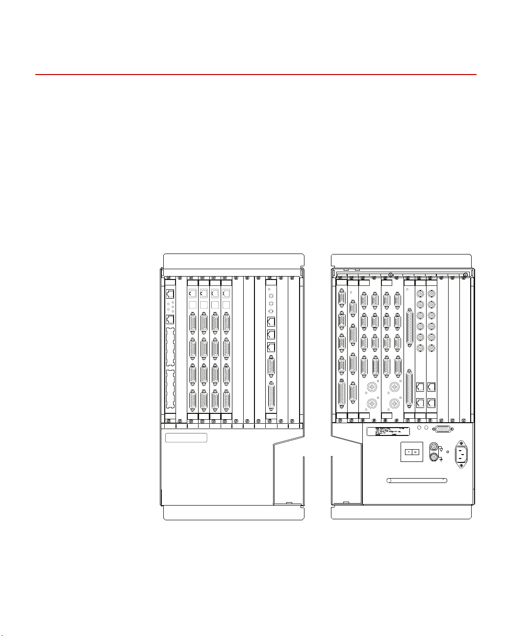
FlexTest GT Controllers
MTS FlexTest GT Controllers are fully digital Proportional, Integral, Derivative,
Feedforward (PIDF) servocontrollers which use an identical chassis
configuration. They provide complete control of up to eight channels distributed
among up to eight stations. Optional station configurations are available (see
“Hydraulic Configurations” on page 243).
Model 493.10 Chassis
FlexTest GT Controllers use the Model 493.10 Chassis. The Model 493.10
Chassis is a multi-station, multi-channel VMEbus chassis which houses up to ten
MTS VMEbus modules in its front panel and up to ten transition modules in its
rear panel.
20
Introduction
Models FlexTest® IIm/GT/SE Controller Hardware
Page 21

Model 493.10 Chassis
Front panel The Model 493.10 Chassis front panel has twelve slots; ten VMEbus slots and
two slots (A and B) which are reserved.
Rear panel The rear panel of the chassis has twelve transition bus slots. Two of these rear
panel slots (slots A and B) can not be used with powered MTS transition
modules. The chassis can be rack mounted or used in a floor standing
configuration.
VMEbus modules The chassis has ten VMEbus slots that support a variety of MTS VMEbus plug-
in modules.
• The chassis requires at least one processor module. The processor module
provides the processing power to manage the other plug-in modules that
make up the controller.
• The chassis can have up to eight I/O Carrier modules. Each I/O Carrier
module supports up to four mezzanine cards.
• An optional Global Resource (GRES) module provides several connections
to communicate with external devices such as a remote station control
module, temperature controller, and other devices.
Transition bus Transition modules are panels plugged into the transition bus located in the rear
of the chassis. Each transition module allows external devices to interface with
the chassis. Transition modules provide the following:
• Hydraulic control connections
• Station control connections
• Analog input and output connections
• Digital input and output connections
• Serial connections
Cable conduit The chassis has a conduit that allows cables to be routed from the front VMEbus
modules to the rear transition modules and out of the chassis.
Power supply Two power supplies are used. One provides +5 V DC and ±15 V DC for the plug-
in modules; the other provides ±12 V DC for plug-in modules and +24 V DC for
hydraulic power and the chassis fan. The power supplies have universal inputs
and will adapt to any line voltage between 90 and 264 V AC.
The power supply is protected with an external circuit breaker in the On/Off
switch that trips at a 10 amp overload. An internal fuse in the power supply is not
user accessible or repairable.
Models FlexTest® IIm/GT/SE Controller Hardware Introduction
21
Page 22

Hydraulic Control
Cooling The chassis is cooled with a fan. An overtemperature sensor is part of the
Hydraulic Control
Interlocks
standard power supply assembly. If the internal chassis temperature exceeds
50ºC, this sensor will light an amber indicator located on the rear of the power
supply module.
Hydraulic control is handled with two transition modules:
• The Model 493.73 HPU Transition module has a connection to control a
hydraulic power unit. It includes connections for an emergency stop button
and digital I/O for system communications.
• Typically, up to four Model 493.74 HSM Transition Modules can be used to
support up to eight HSM stations. Each HSM module includes connections
to support two stations. Each station supports an HSM, a load unit, run/stop
outputs, auxiliary outputs, and interlock controlled outputs.
Two types of interlocks are supported, the system wide interlock and station
interlocks. The system wide interlock shuts down the hydraulic power unit and
all stations, and the station interlock shuts down a single station leaving other
stations running. The emergency stop function on the Model 493.74 HSM
transition board contains two separate circuits, the system wide interlock (HPU)
and the station interlock (HSM).
System wide interlock The emergency stop circuit consists of a loop that only runs through the rear
panel transition boards of the chassis. Any board that generates an interlock by
breaking this system wide loop causes the hydraulic power unit to be shut down.
This will also cause all of the stations to shut down.
Note The emergency stop circuit meets the requirements of the Machinery
Safety Directive (EN 60204-1, 1992, section 9.2.5.4). This means the
emergency stop circuit is hard-wired with electromechanical
components.
Station interlocks Each station represents all of the components associated with an interlock chain.
All of the modules plugged into the chassis can be assigned to stations. If one of
the stations generates an interlock, all of the components assigned to the station
are shut down.
Standard configurations support up to four independent stations.
22
Introduction
Models FlexTest® IIm/GT/SE Controller Hardware
Page 23

Specifications
FlexTest GT Specifications
P
ARAMETER SPECIFICATION
Specifications
Environmental
Tem per atu re
Relative humidity
Altitude
Power input
Input voltage
Input frequency
Input surge
Power
Insulation over
voltage
Pollution degree
Power supply #1
+5 V DC
±15 V DC
For indoor use only
5ºC–40ºC (41ºF–104ºF)
10%–85%, noncondensing
For use at altitudes up to 2000 m
(6500 ft)
power factor corrected universal input
*
100–240 V AC
47–63 Hz
<100 A
<1000 W
Category II
2
maximum draw is 400 W total
40 A
7.5 A
Power supply #2
±12 V DC
+24 V DC
Weight approximately 45 kg (100 lb) in stand
* The specification shown conforms to CE Low Voltage Directive
requirements. The specification allows for 10% of the values stated.
The actual voltage the 493.10 chassis can operate is
90–264 V AC.
Models FlexTest® IIm/GT/SE Controller Hardware Introduction
maximum draw is 400 W total
4 A
10 A
alone configuration
23
Page 24
Specifications
FlexTest SE
Emergency Stop
7
8 9
65
4
3
2
1
.
0
+/-
enter
cancel
FG
Setup
Status
Scope
Meters
Tuning
Config
Limits
Log
Menu
?
A
B
Recall
Enabled
reset
Rewind Run
Hold Stop
Power
Program
Hydraulic
Interlock
Program
Interlock
HPU
HSM
Off Low High
Off
Low
High
Navigate
Monitor 1
Monitor 2
TS-G436
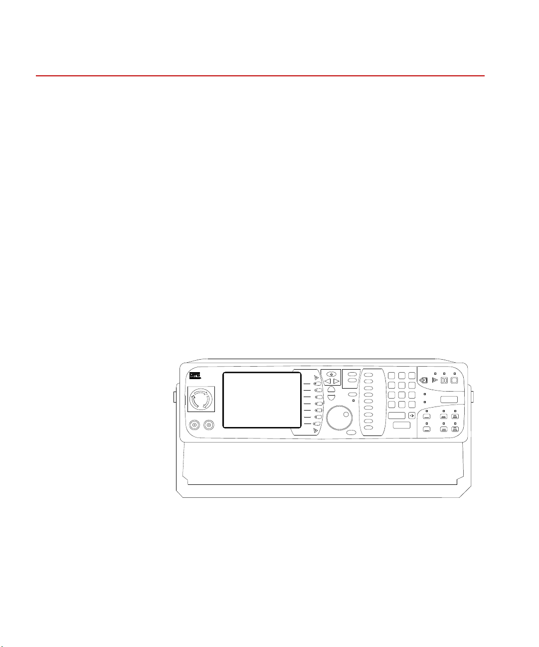
FlexTest SE Controllers
The MTS Model 493.02 FlexTest SE Controller is a fully digital Proportional,
Integral, Derivative, Feedforward (PIDF) servocontroller. It provides complete
control of one servohydraulic channel or station in an MTS test system.
FlexTest SE Controller The FlexTest SE may be operated in the standalone mode from its front panel
controls, or in the automated mode with MTS Model 793.00 System Software
running on a connected PC.
FlexTest SE front panel
controls
Operations are controlled through the controller’s front panel. An easy-to-read
color display shows the status of the parameter currently being adjusted or
monitored. A simple scroll-through menu provides quick access to any parameter
or function. All parameters are entered through a keypad or adjusted by a single
multi-turn dial. The current settings are saved in a flash disk and are recalled at
start up.
In addition to providing the means to adjust and monitor the test parameters, the
front panel also provides program control, system hydraulic pressure control, and
an Emergency Stop button that shuts down the system hydraulics in an
emergency situation. BNC monitor connectors are also provided to allow you to
connect easily to external readout devices.
24
Introduction
FlexTest SE Front Panel
Models FlexTest® IIm/GT/SE Controller Hardware
Page 25

Specifications
FlexTest SE stand-alone
function generation
FlexTest SE automated
configuration
A function generator (with a built-in cycle counter) in the controller provides
basic sine, square, triangle, and ramp command waveforms.
For tests requiring complex waveforms, the controller provides an external
command input to receive externally generated commands.
The function generator waveform can be output to another MTS FlexTest SE
Controller (or any external device) for synchronization.
In the automated configuration, the FlexTest SE Controller has added
capabilities—it can acquire data, perform automated testing, apply complex
control compensation techniques to the servoloop, and execute sophisticated test
procedures that include complex triggering mechanisms.
The automated configuration includes the controller, a personal computer, and
the Model 793.00 System Software bundle. It may also include optional MTS
software for additional capability.
Models FlexTest® IIm/GT/SE Controller Hardware Introduction
25
Page 26
Model 493.02 Chassis
TYPE E PC-MIP
TYPE E PC-MIP
RUN 6TS BFL
ABT RST
DEBUG
PCI MEZZANNE CARD
Power
100–240 VAC
50–60 Hz, 12–6A
TS-G435
Model 493.02 Chassis
FlexTest SE Controllers use the Model 493.02 Chassis. The Model 493.02
Chassis is a single-station, single-channel VMEbus chassis which, in a typical
configuration, houses three plug-in modules:
• A Series 498 Processor
• A Model 493.40 I/O Carrier module
• A Model 493.42 System I/O module
Model 493.02 Chassis
rear panel
Hydraulic Control
Except for two front panel BNC connectors, all cabling is accessed through the
controller’s rear panel. It is not necessary to remove the chassis cover to access
jumpers or switches. The chassis can be rack mounted or used in a table-top
configuration.
FlexTest SE Rear Panel
The controller provides complete control of the test system hydraulics. It can be
used to control a hydraulic power unit and a hydraulic service manifold to apply
low and high hydraulic pressure to the test system. In multiple controller
configurations, the controller provides first-on/last-off control of the hydraulic
power unit in addition to control of a local hydraulic service manifold.
Interlocks
Introduction
26
The controller provides interlocks for adjustable upper/lower limit, underpeak,
error detection for each sensor conditioner installed, and others. These interlocks
can be daisy-chained for multiple controller configurations.
Models FlexTest® IIm/GT/SE Controller Hardware
Page 27

Specifications
FlexTest SE Specifications
P
ARAMETER SPECIFICATION
Specifications
Environmental
Tem per atu re
Relative humidity
Altitude
Power input
Input voltage
Input frequency
Input surge
Insulation over
voltage
Pollution degree
Weight approximately 8.6 kg (19 lb)
* The specification shown conforms to CE Low Voltage Directive
requirements. The specification allows for 10% of the values stated.
The actual voltage the 493.02 chassis can operate is
90–264 V AC.
*
For indoor use only
5ºC–40ºC (41ºF–104ºF)
10%–85%, noncondensing
For use at altitudes up to 2000 m
(6500 ft)
power factor corrected universal input
100–240 V AC
47–63 Hz
<50 A
Category I
2
Models FlexTest® IIm/GT/SE Controller Hardware Introduction
27
Page 28

Specifications
FlexTest IIm Controllers
The MTS FlexTest IIm Controller is a fully digital Proportional, Integral,
Derivative, Feedforward (PIDF) servocontroller.
FlexTest IIm
Controllers
The FlexTest IIm configuration provides complete control of up to sixteen
channels distributed among up to four stations in an MTS test system.
The FlexTest IIm Controller is available in five standard configurations. The
FlexTest IIm Controller also supports optional components and custom
configurations that can add features and capability to any standard configuration.
All configurations include the following components:
• Model 497.01 Analog Chassis
The analog chassis includes a complement of valve drivers and
conditioners:
– Model 497.14 AC Conditioner module
– Model 497.22 Dual DC Conditioner module
– Model 497.26 Dual Valve Driver module
– Model 497.34 Multi-Station Interlock module
– Model 497.36 Communications module
• Model 497.05 Hydraulic Control Panel
The hydraulic control panel controls at least one Hydraulic Power Unit
(HPU) or actuator manifold.
28
Introduction
• Model 498.22 Test Processor Chassis
–Model 498.65 ADDA module
– Model 498.71B GRES III module
– Model 498.96-X Processor module
Models FlexTest® IIm/GT/SE Controller Hardware
Page 29

Specifications
FT IIm standard
configurations
• 4, 6, 8, 12, or 16 channels of control
• 16 inputs and 16 outputs of user DIO
• Per channel resources:
– One valve driver output
– One D/A output
– One A/D input
– One AC Conditioned input
– Two DC conditioned inputs
Console The FlexTest IIm Controller is available in a full-bay (vertical) console, a table-
top console, or a roll-around console.
Note The larger (full-bay) consoles can also accommodate rack-mount
scopes, x-y recorders, and so forth.
Customization A standard FlexTest IIm system can be customized for specific test requirements.
In these cases, the standard hardware and software can be changed to
accommodate a specific customer requirement.
Models FlexTest® IIm/GT/SE Controller Hardware Introduction
29
Page 30

Model 497.01 Analog Chassis
This chassis shows the maximum complement of modules for a standard
FTIIm system. Customized systems can use all the module locations.
Note This chassis has rear panel transition modules and I/O connectors
to support up to four independent test stations.
Out 1
Gnd
Out 2
Gnd
Ch1Ch
2
497.26
Dual Valve
Out 1
Gnd
Out 2
Gnd
Ch1Ch
2
497.26
Dual Valve
Out 1
Gnd
Out 2
Gnd
Ch1Ch
2
497.26
Dual Valve
Out 1
Gnd
Out 2
Gnd
Ch1Ch
2
497.26
Dual Valve
+15V
-15V
-5V
Station
Interlocks
Power OK
497.34
Station Cntrl
1
2
3
4
Reset
497.35
RS422 Com
Fault
Xmit
Ready
x10
x1
497.22
DC Cond
U Lim
L Lim
Excit
Fail
R-Cal
2
Out1
Out2
Gnd
Ch1Ch
2
R-Cal
1
497.22
DC Cond
U Lim
L Lim
Excit
Fail
R-Cal
2
Out1
Out2
Gnd
Ch1Ch
2
R-Cal
1
497.22
DC Cond
U Lim
L Lim
Excit
Fail
R-Cal
2
Out1
Out2
Gnd
Ch1Ch
2
R-Cal
1
497.22
DC Cond
U Lim
L Lim
Excit
Fail
R-Cal
2
Out1
Out2
Gnd
Ch1Ch
2
R-Cal
1
U Lim
L Lim
Excit
Fail
Out
Gnd
497.14
AC Cond
U Lim
LLim
Excit
Fail
Out
Gnd
497.14
AC Cond
U Lim
L Lim
Excit
Fail
Out
Gnd
497.14
AC Cond
U Lim
L Lim
Excit
Fail
Out
Gnd
497.14
AC Cond
Model 497.01 Analog Chassis
The plug-in modules installed in the 497.01 Analog Chassis provide four main
functions:
• Interlock control—An interlock control plug-in module provides
programmable interlock signal mapping between the test processor and the
modules installed in this analog chassis.
• Processor/Analog Chassis communications—A communications module
provides data conversion between the test processor and the 497 analog
plug-in modules.
• Transducer conditioning—AC and DC conditioners provide transducer
excitation and output signal amplification for both low-level and high-level
transducers.
• Valve drive signals—Valve drivers provide drive current for two- and three-
stage servovalves according to command inputs received for each channel.
Analog Chassis (Front Panel)
30
Introduction
Models FlexTest® IIm/GT/SE Controller Hardware
Page 31

Model 497.05 Hydraulic Control Panel
Off Low High
Hydraulic Powe r S upply
Emergency Stop
Over T emp
Low Level
Filter Di rty
Reset
Inter lo cks
Hydraulic
Control
497.05
m
Emergency Stop HSM 1
Int erlo c k 1
Int erlo c k 2
Shutdown
Hyd r au lic D i sa bl ed
Off Pi lot Low Hig h
HSM 2
Interlo ck 1
Interlo ck 2
Shutdown
Hydraulic Disabled
Off Pilot Low High
HSM 3
Interlo c k 1
Interlo c k 2
Shutdown
Hyd r au lic D i sa bl ed
Off Pilot Low High Off Pilot Low High
HS M 4
Inter lock 1
Inter lock 2
Shutdown
Hydra ulic Disabled
The hydraulic control panel provides the following functions.
• Control of up to four independent hydraulic service manifolds
• Hydraulic power supply control
• Interlock shutdown and latched indicators to show interlock status
• Programmable interlock station assignment
• Electrical power outputs to the hydraulic service manifolds and a 497.01
Analog Chassis
• Built-in Emergency Stop button and connections for a remote emergency
stop button
For details about configuring the hydraulic control panel for your system, see the
Series 497 Electronics Product Information manual (PN 100-036-577.)
Model 497.05 Hydraulic Control Panel
Hydraulic Control Panel
Models FlexTest® IIm/GT/SE Controller Hardware Introduction
31
Page 32

Model 498.22 Chassis with Test Processor (FTIIm)
498.65
ADDA
J
1
8
J
1
7
J
1
6
J
1
5
E
X
T
J
1
4
J
1
3
J
1
2
J
1
1
RESET
FAIL
A
D
R
S
m
m
RESET
ABORT
RUN FAIL
J4 NET
J5 CONSOLE
498.71
GLOBAL
RESOURCES
J7 SERIAL
J4 NET
RST
ABT
MOTOROLA
CHS
BFL
CPU
PCI
FUS
SYS
498.93-1
Processor
RST
ABT
MOTOROLA
CHS
BFL
CPU
PCI
FUS
SYS
498.93-2
Processor
Model 498.22 Chassis with Test Processor (FTIIm)
The Model 498.22 test processor chassis is a VMEbus chassis that houses up to
twelve plug-in modules (including processor modules, ADDA modules, digital I/O
modules, and so forth). It also accommodates various rear-panel transition modules
(for connections to other hardware chassis and external equipment).
Note The test processor is covered by a tinted, removable front panel. For
more information, see the Series 498 Electronic Product Information
manual (PN 100-036-578).
32
Introduction
Model 498.22 Test Processor Chassis (Front Panel)
Models FlexTest® IIm/GT/SE Controller Hardware
Page 33

Specifications
Model 497.01 Specifications
P
ARAMETER SPECIFICATION
Specifications
Environmental
Tem per atu re
Relative humidity
Power requirements +15 V at 6 A; -15 V at 6 A; +5 V at 6 A
Dimensions
Height
Width
Depth
For indoor use only
5ºC–40ºC (41ºF–104ºF)
10%–85%, relative, noncondensing
(standard supply maximum output,
actual load depends on installed
modules)
17.8 cm (7 in)
48.3 cm (19 in)
31.1 cm (12.25 in)
Model 497.05 Specifications (part 1 of 2)
P
ARAMETER SPECIFICATION
Individual solenoid current
Total HSM solenoid current
Solenoid operating voltage 24 V DC or 115 V AC (switch
2 A max
6 A max
selectable)
497.05 power supply output
497.01 power supply output
Power requirements 90–132 V AC/180 - 264 V AC
Models FlexTest® IIm/GT/SE Controller Hardware Introduction
+24 V at 7.5 A
+5 V at 6 A
+15 V at 6 A
-15 V at 6 A
47–63 Hz
500 W
33
Page 34

Specifications
Model 497.05 Specifications (part 2 of 2)
P
ARAMETER SPECIFICATION
Interlock logic level inputs 0 = 0 V DC
1 = 3.2 to 24 V DC
Dimensions
Height
Width
Depth
8.9 cm (3.5 in)
48.3 cm (19 in)
54.6 cm (21.5 in)
34
Introduction
Models FlexTest® IIm/GT/SE Controller Hardware
Page 35

Model 498.22 Chassis Specifications
P
ARAMETER SPECIFICATION
Dimensions
Specifications
Height
Width
Depth
Weight 18 kg (40 lb) plus 0.5 kg (1 lb) per
Rack mounting requirements:
Clearance-each side
Clearance-back
Clearance-top/bottom
Number of slots 12 VMEbus slots
Power requirements 100–120 V AC at 12 A between 50–60
LED Classification Class 1
Environmental
Tem per atu re
40 cm (15.75 in)
48.3 cm (19 in)
55.9 cm (22 in)
module
5.7 cm (2.25 in) for air flow
15.3 cm (6.0 in) for cabling
No restrictions
Hz
220–240 V AC at 6 A between 50–60
Hz
For indoor use only
5ºC–40ºC (41ºF–104ºF) ambient
Relative humidity
Maximum altitude
Insulation over
voltage
Pollution degree
Models FlexTest® IIm/GT/SE Controller Hardware Introduction
0%–85%,relative, noncondensing
2000 m (6562 ft)
Category II
2
35
Page 36

Specifications
36
Introduction
Models FlexTest® IIm/GT/SE Controller Hardware
Page 37

Chapter 2
CAUTION
Installation
This chapter describes how to install the Controller chassis and connect it to
system components.
Contents Installing the Model 493.10 Chassis (FTGT) 37
Installing the 493.02 Chassis (FlexTest SE) 49
Installing 497/498 Electronics (FTIIm) 61
Installing the Model 493.10 Chassis (FTGT)
The chassis can be installed in an equipment rack console or in a standalone
configuration.
The Model 493.10 Chassis weighs about 45 kg (100 lb) in stand-alone
configuration.
Improper lifting techniques can cause strained muscles and back injuries.
When lifting this chassis, take the appropriate precautions to prevent injuries to
yourself.
Models FlexTest® IIm/GT/SE Controller Hardware Installation
37
Page 38

Connecting Electrical Power
Stand-alone
installation
The stand-alone chassis can be placed on the floor. The chassis location is limited
only by the length of the system cables. The front panel of the chassis can be
removed to access the VMEbus plug-in modules.
Console installation The rack-mounted chassis can be installed in any Model 490.8x console. Install
the console with the 493.10 Rack Mounting kit (056-139-502 for FlexTest GT).
The Rack Mounting kit provides the hardware (L-shaped brackets) to support the
chassis and mounting screws to secure the chassis to the console rack.
Connecting Electrical Power
Electrical connections must be made by qualified personnel and conform to local
codes and regulations. An electrical service panel to provide the electrical power
feed (line voltage) to the chassis is not necessary, but may be required by local
electrical codes.
Installation
38
Models FlexTest® IIm/GT/SE Controller Hardware
Page 39

Connecting Electrical Power
Signal
Ground
Chassis
Ground
Chassis
ground is connected
through the power cord
connector.
System ground cable
(PN 039-709-2xx)
connected to other
components.
Chassis ground cable
(PN 037-766-102)
connected to the vertical
conductive rail.
System ground cable
(PN 005-402-3xx) connected
to the load frame or other
components.
Signal common cable
(PN 037-766-101)
connected to the power
panel.
Stand-alone
Configuration
Console
Configuration
Note Local electrical codes supersede any information found here.
Grounding The chassis will not function correctly if it is not grounded as shown. Be sure
your power source is also properly grounded. The chassis includes two grounds:
a chassis ground and a signal ground. The two grounding lugs are connected
together with an external shorting bar when the chassis is manufactured.
• For the console configuration, remove the shorting bar from the ground lugs
and connect the chassis ground to the console rail.
• For a stand-alone configuration, always connect the shorting wire to both
ground lugs.
Models FlexTest® IIm/GT/SE Controller Hardware Installation
AC grounding The AC power ground is through the power cord. The power cord must be
plugged into both the chassis and the power source for proper grounding.
39
Page 40

Connecting Electrical Power
CAUTION
Power All equipment related to the chassis should be connected on the same fused
Proper grounding is required for safe operation.
It is also required to meet EMC emission and susceptibility requirements.
power circuit.
The power supply can accept single-phase voltages within 90–264 V AC at
frequencies between 47–63 Hz.
• The maximum continuous power usage is approximately 1000 W. The
current draw depends on the local voltage supply. A 15 amp line should be
adequate for the chassis and the computer.
• The power supply automatically selects the proper voltage range and line
frequency.
• The power supply is protected with an external circuit breaker in the On/Off
switch that trips at a 10 amp overload. An internal fuse in the power supply
is not user accessible or repairable.
• An outlet strip is supplied with the floor-standing chassis.
• The computer components may be plugged directly into the outlet strip of a
vertical console or a floor-standing console.
AC power disconnect Turn off the AC power switch. Remove the AC power cord from the unit. This
will remove all AC power from the Model 493.10 Chassis.
40
Installation
Models FlexTest® IIm/GT/SE Controller Hardware
Page 41

Connecting Electrical Power
Outlet Strip
w/ circuit breaker
Line
Voltage
Outlet Strip
(printer, etc)
Outlet Strip
Power Panel
Outlet Strip
vertical outlet strip
or
Line
Voltage
PowerOKOver
Temp
J39 Power Monitor
Power
l
Power
OK
Over
Temp
J39 Power Monitor
Power
l
Note Be sure to locate the chassis so you have adequate access to
disconnect the power cord from the chassis.
Models FlexTest® IIm/GT/SE Controller Hardware Installation
41
Page 42

Installing the Plug-in Modules
CAUTION
Installing the Plug-in Modules
This section describes how to install the plug-in modules into the chassis. The
modules plug into a backplane connector and are secured to the chassis with a
screw at the top and at the bottom of the module faceplate.
A hardware interface file (.hwi file extension) defines each type of module and
maps each module location for the system software. The .hwi file and the
physical locations for each type of module must match. Recommended standard
module locations are described in the following sections. For more information
on the .hwi file, see the Hwi File Editor manual.
The plug-in modules contain static-sensitive components.
Improper handling of the module can cause component damage.
Be sure to follow these precautions when handling modules:
• Turn off electrical power before installing or removing a module.
• Use a static ground strap to ground yourself to the chassis ground
before touching the chassis or a module.
• Keep unused modules in conductive bags. Also be sure you are
grounded when removing a module from a conductive bag.
• Handle modules with their front panel or circuit card edges. Do not
touch any circuit card components, pins, or circuit connection points.
42
Installation
Models FlexTest® IIm/GT/SE Controller Hardware
Page 43

VMEbus Modules
BFL
CPU
PMC
ABT
RST
J6 I/O
J7 I/O
493.40
I/O Carrier
J3 Service
Shunt Cal
J4 I/O
J5 I/O
m
CLOCK OUT
EVENT OUT
J3 IN
J6 STATION
J7 SERIAL
EVENT IN
J4 OUT
J5 DEBUG
+12V
12345678910
BFL
CPU
PMC
ABT
RST
J6 I/O
J7 I/O
J6 I/O
J7 I/O
J6 I/O
J7 I/O
J6 I/O
J7 I/O
J6 I/O
J7 I/O
J6 I/O
J7 I/O
493.40
I/O Carrier
J3 Service
Shunt Cal
J4 I/O
J5 I/O
m
493.40
I/O Carrier
J3 Service
Shunt Cal
J4 I/O
J5 I/O
m
493.40
I/O Carrier
J3 Service
Shunt Cal
J4 I/O
J5 I/O
m
493.40
I/O Carrier
J3 Service
Shunt Cal
J4 I/O
J5 I/O
m
493.40
I/O Carrier
J3 Service
Shunt Cal
J4 I/O
J5 I/O
m
493.40
I/O Carrier
J3 Service
Shunt Cal
J4 I/O
J5 I/O
m
m
498.98-2
Power PC
m
498.98-2
Power PC
m
498.71B
GRES III
Placement of
VMEbus modules in
the front panel
chassis
VMEbus Modules
The VMEbus compatible modules should be installed in the front panel chassis
slots according to the following guidelines.
• The processor module(s) must be located in the first (and second) slots.
• The GRESIII module (if used) should be located in slot 10. It may also be
located in slot 2 if a second processor is not used.
• I/O carrier modules and/or ADDA II modules can be installed in slots 3 to
10. Install a module in slot 3 and any additional modules to the right of it.
Models FlexTest® IIm/GT/SE Controller Hardware Installation
43
Page 44

VMEbus Modules
1 2 3 4 5 6 7 8
ON
C
2
0
2
3
4
5
6
7
8
9
A
C
E
1F
S1
S2
0
2
3
4
5
6
7
8
9
A
C
E
1F
S2
0
2
3
4
5
6
7
8
9
A
C
E
1F
S3
0
2
3
4
5
6
7
8
9
A
C
E
1F
S1
Setting I/O Carrier
addresses
S
LOT
ADDRESS
12345678910
PPC C20 C22 C24 C26 C28 C2A C2C C2E
Setting I/O Carrier
module addresses
Setting GRES III
module addresses
Use the dipswitch (S1) and rotary dipswitch (S2) on each I/O Carrier module to
set its address in accord with its installed chassis slot as follows:
The dipswitch settings for address C20 is shown below. Increment the rotary
dipswitch as required to complete I/O Carrier module addressing.
The dipswitch settings for address C08 is shown below. Increment the rotary
dipswitch as required to complete GRES III module addressing.
Setting ADDA II
SLOT
ADDRESS
44
Installation
addresses
Use the onboard rotary dipswitches (S3, S2) and front panel rotary dipswitch on
each ADDA II module to set its address in accord with its installed chassis slot as
follows:
12345678910
PPC PPC C40 C41 C42 C43 C44 C4A C4C
Models FlexTest® IIm/GT/SE Controller Hardware
Page 45

VMEbus Modules
0
2
3
4
5
6
7
8
9
A
C
E
1F
S2
0
2
3
4
5
6
7
8
9
A
C
E
1F
S3
0
2
3
4
5
6
7
8
9
A
C
E
1F
On ADDA II
Front Panel
The rotary dipswitch settings for address C40 are shown below. Increment the
front panel dipswitch as required to complete ADDA II module addressing.
Front Panel VMEbus Modules
M
ODEL MODULE NAME FUNCTION
493.40 I/O Carrier Supports up to four mezzanine cards.
493.43 Multi-Box I/O The optional module allows multiple controllers to share a
master hardware synchronization clock and pass station
interlock state information between each other.
493.50 ADDA II This optional module supports up to four 8-channel A/D
(Model 493.55) or D/A (Model 493.56) mezzanine cards. This
module also supports the 8-channel DSPAD, 8-channel
Delta-Sigma A/D, and 4-channel Universal Encoder
mezzanine cards.
498.96-X Processor Provides an interface between the controller and an external
computer. The processor module also manages the plug-in
modules and transition panels.
498.71B GRES III Interfaces with a Remote Station Control (RSC) module and
temperature controllers.
I/O Carrier Mezzanine Cards (part 1 of 2)
M
ODEL MODULE NAME FUNCTION
493.14 Valve Driver Produces the control signal for a Series 252 Servovalve.
493.15 3–Stage Valve Driver Produces the control signal for a Series 256 or 257
Servovalve.
493.21B Universal Conditioner Processes the signals from either an AC or DC-type sensors.
493.25 Universal Conditioner Processes the signals from either an AC or DC-type sensors.
493.45 A/D Converts up to six external analog signals to digital signals for
use by the controller.
Models FlexTest® IIm/GT/SE Controller Hardware Installation
45
Page 46

VMEbus Modules
M
ODEL MODULE NAME FUNCTION
493.46 D/A Converts up to six internal digital signals to analog signals for
493.47 Encoder Processes the signals from an encoder or a Temposonics III
493.48 Acceleration Conditioner Processes the signals from an accelerometer. Each
M
ODEL MODULE NAME FUNCTION
493.55 A/D Converts up to eight external analog signals to digital signals
I/O Carrier Mezzanine Cards (part 2 of 2)
use by external devices.
transducer with an SSI interface.
Acceleration Conditioner mezzanine card can support up to
three accelerometers. Before installing this board, specific
jumpers must be set on the I/O Carrier module. See “I/O
Carrier jumper settings” on page 119 for more information on
jumper settings.
ADDA II Mezzanine Cards
for use by the controller. This board requires the optional
ADDA II module.
46
493.56 D/A Converts up to eight internal digital signals to analog signals
for use by external devices. This board requires the optional
ADDA II module.
493.57 DSPAD Converts up to eight external analog signals to digital signals
for use by the controller. A DSP chip provides digital filtering.
This board requires the optional ADDA II module.
493.59 Universal Encoder Processes the signals from incremental, absolute, and
Temposonics III encoders. This board requires the optional
ADDA II module.
Installation
Models FlexTest® IIm/GT/SE Controller Hardware
Page 47

Installing the Transition Panels
J3 IN
J4 OUT
+12V
m
493.72
Digital I/O
J44BJ44A Run/Stop
J49BJ49A Aux Pwr
J29BJ29A Load Unit
m
J43BJ43A Intlk
J28A HSM
J28B HSM
493.74
HSM
SERVICE
J23
E-STOP OUT
J24
E-STOP IN
J25 HPS
J54
SYS I/O
m
493.73
HPU
Ch 1A In
Ch 2A In
Ch 3A In
m
J12 B Out
J11 B Out
Ch 1B In
Ch 2B In
Ch 3B In
493.78
Accel.
Transition
Ch 1
Ch 2
Ch 3
Ch 4
Ch 5
Ch 6
m
J11
(Ch 1-4)
J12
(Ch 5-6)
493.75
Analog In
Ch 1
Ch 2
Ch 3
Ch 4
Ch 5
Ch 6
m
J11
(Ch 1-4)
J12
(Ch 5-6)
493.76
Analog Out
Ch 1
Ch 2
Ch 3
Ch 4
Ch 5
Ch 6
m
J11
(Ch 1-4)
J12
(Ch 5-6)
493.77
Filtered In
J44BJ44A Run/Stop
J49BJ49A Aux Pwr
J29BJ29A Load Unit
m
J43BJ43A Intlk
J28A HSM
J28B HSM
493.74
HSM
12345678910 BA
J50D
J7 SERIAL
J50C
J50B
J50A
m
493.71
Serial
Interface
Placement of
transition panels
in the rear panel
chassis
The transition panels need to be installed in specific slots of the rear panel
chassis. This is done to allow proper air flow in the chassis. For consistency,
install the modules according to the following guidelines.
Starting from the left chassis slot (slot 10) and working to the right, install the
modules as shown. If you do not have one of the modules, install the next one
you do have. Install multiple modules of the same model number next to each
other.
Installing the Transition Panels
Models FlexTest® IIm/GT/SE Controller Hardware Installation
47
Page 48

Installing the Transition Panels
Note Other transition modules may be used, contact MTS Systems
Corporation for additional information.
Rear Panel Transition Panels
M
ODEL MODULE NAME FUNCTION
493.71 RS485 Provides four channels of RS-485 interface, four channels of
station stop interlocks, and four channels of emergency stop
interlocks. The RS-485 interface channels are used for the
Remote Station Controller and/or temperature controller.
493.72 Digital I/O Contains sixteen general purpose digital input channels and
sixteen general purpose digital output channels.
493.73 HPU Transition Board Interfaces the controller with a hydraulic power unit.
493.74 HSM Transition Board Interfaces the controller with a hydraulic service manifold and
other devices, up to two stations.
493.75 Analog In BNC Provides six BNC channels for analog input signals. The
input signals must be within ±10 V DC.
493.76 Analog Out BNC Provides six BNC channels for analog output signals. The
output signals are within ±10 V DC.
493.77 Filtered Analog Input Provides filtering for the Model 493.45 A/D (analog-to-digital)
modules.
493.78 Accelerometer Transition
Board
493.79 Multiple Universal Driver
Board
493.80 Encoder Transition Interfaces with up to four encoders.
493.81 Analog In BNC Provides up to eight channels of analog input to each Model
493.82 Analog Out BNC Provides eight channels of analog output from the Model
493.83 Filtered Analog Input Provides up to eight channels of filtered analog input to each
Installation
48
Interfaces with up to three low impedance voltage mode
(LIVM) accelerometers and three signal conditioned type
accelerometers.
Provides up to six drivers that can be used to drive standard
252 servovalves. Inputs to this board can originate from
either a ADDA II board (6 outputs) or a Model 493.46
D/A board (6 outputs).
493.55 A/D module. The input signals must be within ±10 V
DC.
493.56 D/A modules. The output signals are within ±10 V DC.
Model 493.55 A/D module.
Models FlexTest® IIm/GT/SE Controller Hardware
Page 49

Installing the Plug-in Modules
CAUTION
Installing the 493.02 Chassis (FlexTest SE)
This section describes how to install the MTS FlexTest 493.02 chassis and
connect it to your system components.
Contents Installing the Plug-in Modules 42
VMEbus Modules 50
Chassis Installation Options 51
Connecting Electrical Power 53
Installing the Handle Kit 58
Installing the Plug-in Modules
This section describes how to install the plug-in modules into the chassis. The
modules plug into a backplane connector and are secured to the chassis with a
screw at the top and bottom of the faceplate.
Models FlexTest® IIm/GT/SE Controller Hardware Installation
The plug-in modules contain static-sensitive components.
Improper handling of the module can cause component damage.
Be sure to follow these precautions when handling modules:
• Turn off electrical power before installing or removing a module.
• Use a static ground strap to ground yourself to the chassis ground
before touching the chassis or a module.
• Keep unused modules in conductive bags. Also be sure you are
grounded when removing a module from a conductive bag.
• Handle modules with their front panel or circuit card edges. Do not
touch any circuit card components, pins, or circuit connection points.
49
Page 50

VMEbus Modules
5
4
3
2
1
TYPE E PC-MIP
TYPE E PC-MIP
RUN 6TS BFL
ABT RST
DEBUG
PCI MEZZAN NE CARD
Placement of
VMEbus modules
in the chassis
VMEbus Modules
The VMEbus compatible modules should be installed in chassis slots according
to the following guidelines.
• The processor module is installed in slot 1
• The I/O carrier module is installed in slot 2.
• The System I/O module is installed in slots 4 and 5.
VMEbus Modules
S
LOT MODULE NAME FUNCTION
Slot 1 Processor Provides PIDF processing for the Controller and
management of the other plug-in modules in the standalone
configuration. Provides an interface between the Controller
and an external computer in the automated configuration.
Slot 2 Model 493. 40 I/O Carrier Supports up to four mezzanine cards that can be used for
sensor conditioning, driving a servovalve, and in the
automated configuration, providing A/D and/or D/A channels.
Slot 3 Blank in standard
configurations.
May be used for additional
Model 493.40 I/O Carrier
(factory installed option for
automated systems)
Slots 4, 5 Model 493.42 System I/O Provides box-in and box-out connections for daisy chaining
Installation
50
Additional carrier chassis that can house up to four
mezzanine cards for expanded sensor conditioning and A/D
and D/A channels
Note This is not a standard option. It is available only for
automated systems and must be configured at the
factory. For more information, contact MTS.
multiple Controllers, analog and digital I/O, E-Stop, and HSM
and HPU control.
Models FlexTest® IIm/GT/SE Controller Hardware
Page 51

Chassis Installation Options
FlexTest SE
Emergency Stop
7
8 9
65
4
3
2
1
.
0
+/-
enter
cancel
FG
Setup
Status
Scope
Meters
Tuning
Config
Limits
Log
Menu
?
A
B
Recall
Enabled
reset
Rewind Run
Hold Stop
Power
Program
Hydraulic
Interlock
Program
Interlock
HPU
HSM
Off
Low High
Off
Low
High
Navigate
Monitor 1 Monitor 2
TS-G436
FlexTest SE
Emergency Stop
7
8 9
65
4
3
2
1
.
0
+/-
enter
cancel
FG
Setup
Status
Scope
Meters
Tuning
Config
Limits
Log
Menu
?
A
B
Recall
Enabled
reset
Rewind Run
Hold Stop
Power
Program
Hydraulic
Interlock
Program
Interlock
HPU
HSM
Off
Low High
Off
Low
High
Navigate
Monitor 1 Monitor 2
TS-G436
FlexTest SE
Controller
with optional
handle kit
Model 493.40 I/O Carrier Mezzanine Cards
M
ODEL MODULE NAME FUNCTION
493.14 Valve Driver Produces the control signal for a Series 252 Servovalve.
493.15 3–Stage Valve Driver Produces the control signal for a Series 256 or 257
Servovalve.
493.25 Universal Conditioner Processes the signals from either an AC or DC-type sensors.
493.45 A/D Converts up to six external analog signals to digital signals for
use by the controller.
493.46 D/A Converts up to six internal digital signals to analog signals for
use by external devices.
493.47 Encoder Processes the signals from an encoder or a Temposonics III
transducer with an SSI interface.
Chassis Installation Options
Models FlexTest® IIm/GT/SE Controller Hardware Installation
The chassis can be fitted with the optional handle kit for table-top use in the
stand-alone configuration (shown below), and for the automated configuration it
can be installed without the handle-kit in a standard MTS equipment rack.
Note For information about installing the optional handle kit, see page 58.
51
Page 52

Chassis Installation Options
Rack Mount Option
The Controller chassis is
designed to fit into a standard
electronics rack.
Rack mounting
requirements
When installing the chassis in an equipment rack allow a minimum of 2 in. (5.1
cm) on either side of the controller for air flow. There are no spacing
requirements for the top or bottom of the controller. If the equipment rack is
equipped with doors, allow adequate clearance for the front and rear of the
controller. The rear of the controller requires a minimum clearance of 6 in. (15.24
cm) to accommodate cables.
The chassis can be installed in any Model 490.8x console. Install the console
with the Model 493.02 Chassis Rack Mounting Kit (PN 100-063-209).
The rack mounting kit provides the hardware (L-shaped brackets) to support the
chassis and mounting screws to secure the chassis to the console rack.
52
Installation
Models FlexTest® IIm/GT/SE Controller Hardware
Page 53

Connecting Electrical Power
Chassis
Ground
Signal
Ground
System ground cable
(PN 037-766-102)
connected to other
components.
Grounding the
chassis
TYPE E PC-MIP
TYPE E PC-MIP
RUN 6TS BFL
ABT RST
DEBUG
PCI MEZZANNE CARD
Power
100–240 VAC
50–60 Hz, 12–6A
TS-G435
Chassis ground is
connected through the
power cord connector.
Electrical connections must be made by qualified personnel and conform to local
codes and regulations. An electrical service panel to provide the electrical power
feed (line voltage) to the chassis is not necessary, but may be required by local
electrical codes.
Note Local electrical codes supersede any information found here.
Grounding The chassis will not function correctly if it is not grounded as shown. Be sure
your power source is also properly grounded. The chassis includes two grounds:
a chassis ground and a signal ground. The two grounding lugs are connected
together with an external shorting bar when the chassis is manufactured.
Connecting Electrical Power
• For the console configuration, remove the shorting bar from the ground lugs
and connect the chassis ground to the console rail.
• For a stand-alone configuration, always connect the shorting bar to both
ground lugs.
Models FlexTest® IIm/GT/SE Controller Hardware Installation
53
Page 54

Connecting Electrical Power
System ground cable
(PN 005-402-3xx) connected to
the test frame or other
components.
Rack Mount Configuration
Signal common cable
(PN 037-766-101) connected
to the power panel.
Chassis ground cable
(PN 037-766-102) connected
to the vertical conductive rail.
CAUTION
Installation
54
The AC power ground is through the power cord. The power cord must be
plugged into both the chassis and the power source for proper grounding.
Proper grounding is required for safe operation.
It is also required to meet EMC emission and susceptibility requirements.
Models FlexTest® IIm/GT/SE Controller Hardware
Page 55

Connecting Electrical Power
Power All equipment related to the chassis should be connected on the same fused
power circuit.
• The power supply can accept single-phase voltages within 90–264 V AC at
frequencies between 47–63 Hz.
• The maximum continuous power usage is approximately 300 W. The
current draw depends on the local voltage supply. A 15 amp line will be
adequate for the chassis and the computer.
• The power supply automatically selects the proper voltage range and line
frequency.
• The power supply is protected with an external circuit breaker in the On/Off
switch that trips at a 5 amp overload. An internal fuse in the power supply is
not user accessible or repairable.
AC power disconnect Turn off the AC power switch. Remove the AC power cord from the unit. This
will remove all AC power from the Model 493.02 Chassis.
Models FlexTest® IIm/GT/SE Controller Hardware Installation
55
Page 56

Connecting Electrical Power
TYPE E PC-MIP
TYPE E PC-MIP
RUN6TS BFL
ABT R ST
DEBUG
PCI MEZZANNE CARD
Power
100–240 VAC
50–60 Hz, 12–6A
Outlet Strip
w/ circuit breaker
Line
Vol tage
Stand-Alone Configuration
Line
Vol t age
Outlet Strip
(printer, etc)
TYPE E PC-MIP
TYPE E PC-MIP
RUN6TS BFL
ABT RST
DEBUG
PCI MEZZANNE CARD
Power
100–240 VAC
50–60 Hz, 12– 6A
Outlet Strip
w/ circuit breaker
Automated Configuration
Note Be sure to locate the chassis so you have adequate access to
disconnect the power cord from the chassis.
Installation
56
Models FlexTest® IIm/GT/SE Controller Hardware
Page 57

Connecting Electrical Power
Power Panel
Outlet Strip
or
TYPE E PC-M IP
TYPE E PC-MIP
RUN6TSBFL
ABTRST
DEBUG
PCI MEZZANNE CARD
Power
100–240 VAC
50–60 Hz, 12–6A
Rack Mounted Configuration
Models FlexTest® IIm/GT/SE Controller Hardware Installation
57
Page 58

Installing the Handle Kit
Installing the Handle Kit
The controller may be equipped with an optional handle kit.
The following procedure provides assembly and installation instructions for the
handle kit (MTS PN 100-061-494). The following table and figure show the
handle kit assembly components described in the procedure.
I
TEM DESCRIPTION QUANTITY
1 Support arm 2
2 Handle side leg 2
3 Clip 2
4 Washer 4
5 Screw 2
6 Spring 2
Handle Kit Parts
58
Installation
7 Button 2
8 Ratchet 2
9 Ratchet housing 2
10 Lock washer 2
11 Handle screw 2
12 Handle 1
13 Cover 2
Models FlexTest® IIm/GT/SE Controller Hardware
Page 59

Installing the Handle Kit
1
2
3
4
5
6
7
8
9
10
11
12 (handle-not shown)
13
Handle Kit
1. Place one support arm (1) into one handle side leg (2), as shown in the
handle kit assembly figure.
2. Set one of the clips (3) in place over the slender, straight portion of the
support arm (1), just behind the circular end of the support arm.
3. Insert two washers (4) and a screw (5) through the mounting hole in the
handle side leg (2).
4. Insert a spring (6) and a button (7) into the handle side leg mounting hole,
over the screw (5) and washers (4).
5. Press the button (7) into the handle side leg, as far as you can and push a
ratchet (8) over the button (7) leg detentes, until it snaps into place over the
first set of detentes. Make certain the burred or sharper edges of the ratchet
are pointing toward the handle side leg.
6. Hold a ratchet housing (9) in place over the ratchet (8) and press the posts on
the back side of the ratchet housing (9) into the mounting holes on the side
Models FlexTest® IIm/GT/SE Controller Hardware Installation
panel of the controller.
59
Page 60

Installing the Handle Kit
7. Insert a Phillips screwdriver through the hole in the button (7) and lightly
tighten the screw (5).
8. Assemble the remaining handle kit components to the other handle side leg
(2) according to steps 1 through 7 and mount the side leg to the mounting
holes on the opposite side of the controller.
9. Insert a lock washer (10) and handle screw (11) through the mounting hole
at the end of one handle side leg (2) and lightly tighten to handle (12).
Repeat this step for the other handle side leg, then secure both screws (11).
(The mounting screw for the first handle side leg may have to be loosened
slightly to allow the second handle side leg to be mounted.)
10. Snap cover (13) in place over the handle screw (11) and lock washer (10).
11. Secure mounting screws (5) on each side of the controller.
12. Press in both buttons (7) and rotate the handle assembly. The assembly
should rotate up and down easily. When the buttons (7) are released, the
handle should lock into a detente position and remain there. If the handle
does not move easily, or if it does not lock into a detente position, an error
may have been made during the assembly. Take a small straight blade screw
driver and carefully remove the covers (13), loosen all screws and remove
the handle assembly from the controller. Reassemble the handle side leg
assemblies according to steps 1 through 7.
60
Installation
Models FlexTest® IIm/GT/SE Controller Hardware
Page 61

Connecting the Console and Chassis Power
Installing 497/498 Electronics (FTIIm)
Contents Connecting the Console and Chassis Power 61
Grounding the Console and Chassis 62
Model 497.01 Analog Chassis 63
About Analog Chassis Slots 63
Analog Chassis Plug-in Modules 64
Analog Chassis Transition Modules 66
Adding an Analog Chassis to Your Console 69
Model 497.05 Hydraulic Control Panel 71
Test Processor Plug-in Modules 72
Test Processor Transition Modules 74
Connecting the Console and Chassis Power
Each chassis installed in your console can be configured for 115 or 230 V AC
service. To configure each chassis for 230 V AC service, refer to the following
product manuals.
• Model 497.05 Hydraulic Control Panel (100-036-577)
• Model 497.01 Analog Chassis (100-036-577)
• Model 498.22/498.23 Test Processor (100-036-578)—for FlexTest IIm
How To Connect the Chassis Power Cables
You can plug the hydraulic control panel and the test processor chassis into the
AC power strip inside the console.
The analog chassis requires an external power supply. Typically, it is connected
to the hydraulic control panel. If you have more than one analog chassis, you
must plug each additional analog chassis into a remote power supply.
Models FlexTest® IIm/GT/SE Controller Hardware Installation
61
Page 62

How To Cable the Analog Chassis to the Hydraulic
J50
J1
497.05 Hydraulic Control Panel
497.01 Analog Chassis
PN 046-239-1xx
How To Cable the Analog Chassis to the Hydraulic Control Panel
Connect J50 DC Pwr on the 497.01 Analog Chassis rear panel to J50 on the
497.05 Hydraulic Control Panel rear panel.
Grounding the Console and Chassis
The system will not function correctly if it is not grounded properly.
The power ground and chassis ground terminals are wired together when the
chassis is manufactured.
Remove the jumper between the two grounds and connect each terminal as
62
Installation
follows:
• Each chassis ground should be connected to the console with a short ground
cable (PN 037-766-102).
• Each power ground should be connected at a common location on the power
panel (PN 037-766-1xx).
• The power panel ground should be connected to the console (PN 037-766-
101).
The system ground cable connects the console to other system components (PN
005-402-3xx).
Models FlexTest® IIm/GT/SE Controller Hardware
Page 63

Model 497.01 Analog Chassis
Slots 1–2
Slots 3–4
Slots 5–6
Slots 7–8
Slots 9–10
Slots 11–12
Slots 13–14
Slots 15–16
Model 497.01 Analog Chassis
About Analog Chassis Slots
Slot pairing Chassis slot assignments are grouped in pairs. If you have a conditioner in a slot,
then you cannot have a valve driver installed in the slot paired with it. Slots are
paired as follows:
Slot assignments The analog chassis contains 18 bus-board slots for plug-in modules. Each slot is
reserved for a particular type of plug-in module.
Slot A Reserved for the Model 497.34 Multistation Interlock Module.
Slot B Reserved for the Model 497.36 Communications Module.
Slots 1–4 These slots are reserved for up to four AC conditioners.
Slots 5–8 These slots are reserved for up to four DC conditioners.
Slots 9–12 These slots are reserved for options (not used with standard systems).
Slots 13–16 These slots are reserved for up to four valve drivers.
Models FlexTest® IIm/GT/SE Controller Hardware Installation
63
Page 64

Analog Chassis Plug-in Modules
Analog Chassis Plug-in Modules
Before you install any plug-in modules, be sure they are configured properly for
your system. The following is a brief description of the plug-in modules available
for the chassis.
Plug-in Modules
M
ODEL #PLUG-IN MODULE NAME FUNCTION
*
497.13
AC Conditioner
Processes signals from AC-type sensors such as LVDTs or
RVDTs.
Note This module was designed to replace the Model
497.14 AC Conditioner.
497.15 Three-Stage Valve Driver
Produces the control signal and inner control loop for a Series
256 Servovalve or Series 257 Servovalve.
*
497.22
Dual DC Conditioner
Processes the signals from two DC-type sensors such as a
force transducer or extensometer.
497.26 Two-Stage Valve Driver
Produces the control signal for one Series 252 Servovalve.
The second valve driver is not used in standard systems.
497.34 Multistation Interlock
Controller
Monitors the plug-in modules for interlocks. This is a part of
the interlock chain between Model 497.05 Chassis and any
other 497.01 chassis.
497.36 Communication Module
Provides communications between the Model 497.01 Analog
Chassis and the Model 498.22 Test Processor.
* This conditioner is normalized and can be swapped (with a conditioner of the same model number)
without recalibrating the sensor/conditioner pair. Normalized conditioners contain an EEPROM in
which normalization values are stored during manufacturing. These values compensate for
variations in conditioner components.
64
Installation
Models FlexTest® IIm/GT/SE Controller Hardware
Page 65

How to Install or Remove a Plug-in Module
CAUTION
Plug-in modules are static sensitive.
Do not install or remove a module with electrical power on. Do not place modules
that contain battery backup on a metal surface. Touch the console or other ground
point before handling a module. Avoid making physical contact with any circuitry
on the modules. Maintain the same potential between the module circuitry and the
equipment or surfaces it contacts by touching the surfaces first or wearing a wrist
strap connected to chassis ground.
To install a module in the chassis:
1. Fully retract the two screws near the handles.
2. Insert the module assembly, and gently slide the module in until it connects
with the backplane.
3. Ensure that the circuit card is seated in the backplane connectors and tighten
the two screws.
How to Install or Remove a Plug-in Module
To remove a module from the chassis:
1. Loosen the two screws near the module handles.
2. Tug gently on the module to unseat it from the backplane connectors.
3. Slide the module straight out of the chassis.
Models FlexTest® IIm/GT/SE Controller Hardware Installation
65
Page 66

Analog Chassis Transition Modules
J1602 J1502 J1402 J1302 J1202 J1102 J1002 J902 J802 J702 J602 J502 J402 J302
J202
J102
System
J1601 J1501 J1401 J1301 J1201 J1101 J1001 J901 J801 J701 J601 J501 J401 J301 J201 J101
J38
Aux
J28
I/O
J37
Aux
J27
I/O
J36
Aux
J26
I/O
J35
Aux
J25
I/O
J34
Aux
J24
I/O
J33
Aux
J23
I/O
J32
Aux
J22
I/O
J31
Aux
J21
I/O
J41
Com In
J42
Com Out
J43
XPTR In
J51
Intlk In
J50
DC Pwr
J44
XPTROut
J52
IntlkOut
16 15 14 13 12 11 10 9 8 7 6 5 4 3 2 1 A B
Chassis Slot Number
Analog Transition Modules Digital Transition
Modules
Transition modules in the rear panel chassis
Analog Chassis Transition Modules
Transition modules located on the Model 497.01Rear Panel provide signal
transfer between the Model 497 modules and external devices. One digital
transition module and up to eight analog transition modules can be installed in
this chassis. Each transition module plugs into the backplane connectors and
connects to two chassis slot locations.
How To Install a Transition Module
1. To install a transition module, remove the appropriate panel cover from the
analog chassis.
66
Installation
2. Plug the transition modules into the backplane connectors. Refer the
following table for transition module slot assignments.
Slot Assignment
M
ODULE TYPE SLOT ASSIGNMENT
Analog Transition
Digital Transition
1–2, 3–4, 5–6, 7–8, 9–10, 11–12, 13–14, 15-16
A–B
3. Replace the panel cover and fasten the screw locks on all D connectors.
Models FlexTest® IIm/GT/SE Controller Hardware
Page 67

Transition Module Connectors
Cable connections to external devices are made from the 497.01 chassis rear
panel connectors.
J101–J1601 System connectors J101 through J1601 (JX01) are 15-pin D-type connectors
located on the chassis rear panel. They connect either a valve driver to a
servovalve or a conditioner to a transducer. The cable that is plugged into these
connectors depends on whether a valve driver or a conditioner is installed in the
corresponding chassis slot location.
J102–J1602 Connectors J102 through J1602 (JX02) provide a second connection for dual
conditioners, dual valve drivers, or three-stage valve drivers. Each module has
four rear panel connectors associated with it (Jx01, Jx02, J2x, and J3x).
J21–J28 Rear panel I/O connectors J21 through J28 (J2X) are 15-pin D-type connectors
located on the chassis rear panel. They are used to connect either a valve driver to
D/A converters (command) or a conditioner to A/D converters (feedback).
J31–J38 Rear panel Aux connectors J31 through J38 provide the same signals as J21
through J28 and are used to connect external readout devices.
Transition Module Connectors
J41 and J42 Rear panel communication connectors J41 Com In and J42 Com Out are
associated with the communication module installed in slot B. This connector
allows serial communication with a host computer.
Single chassis
configuration
Multichassis
If you have a single analog chassis, install a cable (PN 056-027-101) from a
Series 498 host computer serial port (debug) to J41 Com In on the Model 407.05
Hydraulic Control Panel, then from J42 Com Out to J41 Com In on the Model
497.01 Analog Chassis.
If you have a multiple analog chassis:
configuration
1. Install a cable from a Series 498 host computer serial port (debug) to J41
Com In on the Model 497.05 Hydraulic Control Panel, then from J42 Com
Out to J41 Com In on the first Model 497.01 Analog Chassis.
2. Install a chassis interconnect cable (PN 046-350-902) from J42 Com Out of
the first Model 497.01 Analog Chassis to J41 Com In of the next analog
chassis. Install as many cables as needed to connect all the chassis.
J43 and J44 These connectors are not used.
J51 and J52 Rear panel interlock connectors J51 Intlk In and J52 Intlk Out are associated
with the interlock controller module installed in slot A. Each connector handles
up to four test stations.
Models FlexTest® IIm/GT/SE Controller Hardware Installation
67
Page 68

Transition Module Connectors
Single chassis
configuration
Multichassis
configuration
If you have a single analog chassis:
First install a cable from a Series 498 host computer serial port (debug) to J51
Intlk In on the Model 497.05 Hydraulic Control Panel, then from J52 Intlk Out
to J51 Intlk In on the Model 497.01 Analog Chassis. Then install jumper plug
assembly (PN 046-350-701) to J52 Intlk Out on the analog chassis.
If you have a multiple analog chassis:
1. Install the cable from the chassis to J51 Intlk In on the Model 497.05
Hydraulic Control Panel, then from J52 Intlk Out to J51 Intlk In on the
first Model 497.01 Analog Chassis (see “Interlock Connections” on page
192).
2. Install a chassis interconnect cable from J52 Intlk Out of the first analog
chassis to J51 Intlk In of the next chassis. Install as many cables as needed
to connect all the chassis.
3. On the last chassis, install jumper plug assembly (PN 046-350-701) to J52
Intlk Out.
68
Installation
Models FlexTest® IIm/GT/SE Controller Hardware
Page 69

Adding an Analog Chassis to Your Console
Adding an Analog Chassis to Your Console
To accommodate higher channel counts, it may be necessary to add one or more
Model 497.01 Analog Chassis’ to your FlexTest IIm console.
Depending on the number of analog chassis installed, you may have to modify
switch settings and jumpers on the communication boards in your 497.05
Hydraulic Control Panel and in the 497.01 Analog Chassis.
The analog chassis and the hydraulic control panel use identical communication
boards. For jumper and switch locations, see “Jumper and switch locations” on
page 70. Configure the jumpers and switches for each chassis according to the
following table.
Communication Modules Switch and Jumper Settings
C
HASSIS X1 SWITCH (S3) JUMPERS X1, X2, X3 JUMPER X5
For a single analog chassis:
497.01 Analog Chassis 1 Set to 1 Remove Install 3 and 4
*
497.05 Hydraulic Control
Panel
For multiple analog chassis:
497.01 Analog Chassis 1 Set to 1 Remove Install 3 and 4
497.01 Analog Chassis 2
(optional)
497.01 Analog Chassis 3
(optional)
497.01 Analog Chassis 4
(optional)
497.05 Hydraulic Control
Panel
* Jumper X5 is used for the RS-232 communications link (between the first chassis and the test
processor) and the RS-422 communications link (between the 497 communications modules in each
chassis).
† The address switch on the hydraulic control panel should be set to the last number in the chassis
chain. For example, if you have a single 497.01 Analog Chassis, you should set the 497.05 Hydraulic
Control Panel address to 2. If you have two analog chassis, you should set it to 3, and so forth.
Set to 2 Install Install 1 and 2
Set to 2 Remove Install 3 and 4
Set to 3 Remove Install 3 and 4
Set to 4 Remove Install 3 and 4
Set to 5
†
Install Install 1 and 2
Models FlexTest® IIm/GT/SE Controller Hardware Installation
69
Page 70

Adding an Analog Chassis to Your Console
4 1
3 2
X1
X5
X3 X2
S3
X4
X6
3
1
14 8
S4
S3
X10
X1
1 7
Jumper and switch
locations
The following graphic illustrates the jumper locations on the Model 497.36
Communication Module.
Communication Module Jumper and Switch Locations
70
Installation
Models FlexTest® IIm/GT/SE Controller Hardware
Page 71

Model 497.05 Hydraulic Control Panel
I
O
J41
Com In
J8
Hyd Enab
J15C
J16C
J17C
J15B
J16B
J17B
J15A
J16A
J17A
J1
497.01 Power
J26
Remote E-Stop
J25
HPS
J52
Intlk Out
J51
Intlk In
J42
Com Out
J9
Mstr/Slv
J28D
J15D
J16D
J17D
J28C J28B J28A
The rear panel connectors of the hydraulic control panel are cabled to the
hydraulic components of your system. The connectors also interface with the
Model 497.01 Analog Chassis and Model 498.22 Test Processor chassis.
Hydraulic Control Panel
J1 The 497.05 contains the power supply for a Model 497.01 Analog Chassis.
Connect your 497.01 Analog Chassis to J1.
Model 497.05 Hydraulic Control Panel
J8 This connector communicates hydraulic status with the Model 498.22 Test
Processor chassis.
J9 This connector is not used in a standard FlexTest IIm system.
J15A–J17D Each HSM channel has a set of three user defined interlock inputs (Interlock 1,
Interlock 2, and Shutdown). These inputs can be configured to monitor contact
closure or to accept logic level inputs.
J25 This connector controls the hydraulic power supply (HPS).
J26 This connector accommodates a remote Emergency Stop switch.
J28A–J28D These connectors control up to four hydraulic service manifolds (HSMs).
J41 and J42 These connectors create a serial communications loop between all of the chassis
in your system.
J51 and J52 These connectors create an interlock communications loop with the other chassis
in your system.
Models FlexTest® IIm/GT/SE Controller Hardware Installation
71
Page 72

Test Processor Plug-in Modules
Test Processor Plug-in Modules
The following table provides a brief description of the plug-in modules installed
in your test processor chassis.
Test Processor Plug-In Modules
M
ODULE FUNCTION
Processor Modules
498.71B Global Resources III
(GRES III)
498.65 ADDA
493.50 ADDA II
498.70 Digital I/O
Standard FlexTest IIm Controllers have two processors installed in the
Model 498.22 Chassis:
• The first processor (in slot 1) communicates with the external
computer.
• The second processor (in slot 3) performs the digital control
functions.
A third processor will be installed (in slot 3 or 5) to handle time history
data acquisition if you purchased the time history data acquisition
option.
Provides the digital input and output interface to devices like external
temperature controllers and remote station controllers. It provides four
serial ports and monitors interlocks from the 497 modules.
Provides analog-to-digital (A/D) processing and digital-to-analog (D/A)
processing. Each function is performed by a mezzanine card. The
standard ADDA module contains two A/D mezzanine cards and one D/
A mezzanine card. A fourth mezzanine card can be added as an option.
See the ADDA product manual.
This optional module supports up to four 8-channel A/D (Model 493.55)
or D/A (Model 493.56) mezzanine cards. This module also supports the
8-channel DSPAD, and Universal Encoder mezzanine cards.
Provides the means to monitor external logic levels and contact status,
and to provide logic level outputs for external device control.
72
Installation
Models FlexTest® IIm/GT/SE Controller Hardware
Page 73

ADDA II mezzanine cards
M
ODULE NAME FUNCTION
Test Processor Plug-in Modules
493.55 A/D
493.56 D/A
493.57 DSPAD
493.59 Universal Encoder
Converts up to eight external analog signals to digital signals for use by the
controller. This board requires the optional ADDA II module.
Converts up to eight internal digital signals to analog signals for use by
external devices. This board requires the optional ADDA II module.
Converts up to eight external analog signals to digital signals for use by the
controller. A DSP chip provides digital filtering.
This board requires the optional ADDA II module.
Processes the signals from incremental, absolute, and Temposonics III
encoders. Each type of encoder requires a specific encoder mezzanine
card.
This board requires the optional ADDA II module.
Models FlexTest® IIm/GT/SE Controller Hardware Installation
73
Page 74

Test Processor Transition Modules
J3C
Sta 3
Intlk
J4
497
Hyd
J6
I/O
J5
497
Intlk
J3D
Sta 4
Intlk
J3A
Sta 1
Intlk
J3B
Sta 2
Intlk
498
SYSTEM
DIGITAL I/O
498
DIGITAL I/O
TRANSITION
MODULE
J4 OUT
+5V +12V
J3 IN
J7
I/O
+5V +12V
1 - 2
DIGITAL I/O ACCESS PANEL
DIGITAL IN1-16
DIGITAL OUT1-16
Digital Input
Channels
3 - 4
5 - 6
7 - 8
9 - 10
11 - 12
13 - 14
15 - 16
1 - 2
3 - 4
5 - 6
7 - 8
9 - 10
11 - 12
13 - 14
15 - 16
Digital Output
Channels
J50A
J50B
J50C
498
RS-485
Transition
Module
J50D
J7
+12V +5V
J11
(CH 1-4)
J12
(CH 5-8)
498
ANALOG
OUT
CH 1
CH 2
CH 3
CH 4
CH 5
CH 6
CH 7
CH 8
J11
(CH 1-4)
J12
(CH 5-8)
498
INPUT
FILTER
CH 1
CH 2
CH 3
CH 4
CH 5
CH 6
CH 7
CH 8
Test Processor Transition Modules
Transition modules are screwed into the back of the test processor chassis. Each
rear-panel transition module corresponds to a plug-in module (or plug-in module
mezzanine card) installed in the front of the chassis.
Transition modules interface with the other test components via connectors for
external digital, analog, and communication cables.
74
Installation
Transition Modules (Model 498.22 Chassis Rear Panel shown)
Models FlexTest® IIm/GT/SE Controller Hardware
Page 75

Test Processor Transition Modules
T
RANSITION MODULE FUNCTION
Test Processor Transition Modules
498 Analog Out
498 Input Filter
498 RS-485 Transition Module
498 System Digital I/O
Transition Module
498 Digital I/O Transition
Module
This module includes eight BNC connectors that provide
analog outputs from the Model 498.65 ADDA module. These
outputs are associated with a D/A mezzanine card.
Four analog outputs are available with the standard ADDA
module. Additional outputs require a second ADDA module
(or an optional fourth mezzanine card).
This module includes eight BNC connectors that provide
filtered analog inputs to the Model 498.65 ADDA module.
These inputs are associated with an A/D mezzanine card.
Four-channel systems use a standard ADDA module which
provides four analog inputs. For 8-channel systems, a second
ADDA module (or an optional fourth mezzanine card) is
required to provide the other four inputs.
This module provides serial connections for use with remote
station controllers (RSCs) or Eurotherm temperature
controllers.
The System Digital I/O Transition module is double-width
module that provides connection to the system digital I/O and
the station interlocks on the Model 498.71B GRES III module.
This transition module provides 16 channels of user-defined
digital inputs and outputs. In order to use these digital inputs
and outputs, this module must be connected to a Model 498
Digital I/O Access Panel.
Note On some custom FlexTest IIm Controllers, this module
must be connected to a Model 498 Remote Digital I/O
Access Panel.
493.80 Encoder Transition
493.81 Analog In BNC
Interfaces with up to four encoders.
Provides up to eight channels of analog input to each Model
493.55 A/D module. The input signals must be within ±10 V
DC.
493.82 Analog Out BNC
Provides eight channels of analog output from the Model
493.56 D/A modules. The output signals are within ±10 V DC.
493.83 Filtered Analog Input
Provides up to eight channels of filtered analog input to each
Model 493.55 A/D module.
Models FlexTest® IIm/GT/SE Controller Hardware Installation
75
Page 76

UPS Systems
UPS Systems
UPS Systems for FlexTest 60, 100, 200, and GT Controllers
To provide an increased level of safety, such as needed to address current
European Machinery Directive, any system using an FT60, FT100, FT200, or
FTGT servo controller must have an acceptable Uninterruptable Power Supply
(UPS) properly integrated into the system.
It is important to note that the UPS will not prevent any unexpected motion if the
controller, or any other electrical subsystem required for control of the system
has an internal failure, including a HPU or a Motor Drive.
UPS requirements • The UPS must be wired to provide power to the controller and any
peripheral equipment that is instrumental in safe system operation and shutdown. In some cases it may be feasible and appropriate to provide UPS
power to the Hydraulic Power Unit (HPU).
• The UPS must be sized to provide adequate electrical power for a period of
three minutes after loss of input power.
• The controller must be configured to take appropriate actions for safe shut-
down of hydraulic equipment being controlled. (Appropriate actions depend
on the particular system.)
76
Battery power
considerations
Installation
• Both UPS input power and UPS output power connections must include
strain relief and a twist-lock plug or equivalent.
• UPS systems used in the European Union must be CE marked.
• The UPS must have input power-loss (AC Fail) alarm relay contact out and
a low battery alarm relay contact out, both of which must be wired to the
controller's UPS monitoring interface.
A UPS with an AC Fail relay contact wired to the controller provides a
mechanism for the controller to identify that the UPS has switched over to
battery power due to a detected AC power failure condition from the facility's
power grid. This fault signal from the UPS can be used by the controller to start a
safe shutdown sequence, ramp command(s) to a safe state(s), and then shut off
the power source.
The addition of a low battery warning relay contact out from the UPS will
provide additional system safety protection by letting the controller know that the
UPS battery is low.
Models FlexTest® IIm/GT/SE Controller Hardware
Page 77

UPS Systems for FlexTest 40 and FlexTest SE
UPS Systems for FlexTest 40 and FlexTest SE Servocontrollers
To provide an increased level of safety and to address current European
Machinery Directive, any system using an FT40, or FTSE servo controller must
have an acceptable Uninterruptible Power Supply (UPS) properly integrated into
the system.
It is important to note that the UPS will not prevent any unexpected motion if the
controller, or any other electrical subsystem required for control of the system
has an internal failure, including a HPU or a motor drive.
UPS requirements • The UPS must be wired to provide power to the servocontroller and any
peripheral equipment that is instrumental in safe system operation and shutdown. In some cases it may be feasible and appropriate to provide UPS
power to the hydraulic power unit (HPU).
• The UPS must be sized to provide adequate electrical power for a period of
three minutes after loss of input power.
• The controller must be configured to take appropriate actions for safe shut-
down of hydraulic equipment being controlled. (Appropriate actions depend
on the particular system.)
Battery power
considerations
• Both UPS input power and UPS output power connections must include
strain relief and a twist-lock plug or equivalent.
• UPS systems used in the European Union must be CE marked.
• FT40 (with Model 494.41 System board) and FTSE controllers do not have
dedicated UPS monitoring inputs.The UPS must have input power-loss (AC
Fail) alarm relay contact out and a low battery alarm relay contact out, both
of which must be wired to two of the digital inputs that are part of generaluse DI/O in the FT40 or FTSE controllers.
Note FT40 controllers that include a Model 494.44 or a Model 494.42 system
board have dedicated UPS inputs.
• The controller’s “Event Action” feature must be configured to take
appropriate actions for safe shut-down of hydraulic equipment being
controlled. (Appropriate actions depend on the particular system.)
A UPS with an AC Fail relay contact wired to the controller provides a
mechanism for the controller to identify that the UPS has switched over to
battery power due to a detected AC power failure condition from the facility's
power grid. This fault signal from the UPS can be used by the controller to start a
safe shutdown sequence, ramp command(s) to a safe state(s), and then shut off
the power source.
Models FlexTest® IIm/GT/SE Controller Hardware Installation
77
Page 78

Specifications–UPS Systems Used with MTS
The addition of a low battery warning relay contact out from the UPS will
provide additional system safety protection by letting the controller know that the
UPS battery is low.
Specifications–UPS Systems Used with MTS Controllers
Any UPS used with an MTS system must comply with these specifications.
UPS Specifications
I
TEM REQUIREMENT
Operating temperature 5–40 deg C
Operating humidity 5–85% non-condensing
UPS power
requirements
Supported UPS output
voltage range
Input/output frequency
range
Output load regulation -/+5% nominal operating voltage (both in
Switch-over time to battery
on power loss
100–240 V AC nominal, single phase,
sine-wave output
50–60 Hz
battery and normal operation modes)
0 s (recommended), < 6 ms (required)
The following UPS power requirements include power for the PC, MTS
Controller (one chassis), and 25% capability for other subsystems.
UPS Power Requirements
C
ONTROLLER TYPE CONTROLLER CHASSIS UPS POWER REQUIRED
FlexTest SE 493.02 1200 watt
FlexTest GT 493.10 2500 watt
Aero ST 493.20 3500 watt
Flextest 40 494.04 1200 watt
FlexTest 60 494.06 1800 watt
78
Installation
FlexTest 100 494.10 2500 watt
FlexTest 200 494.20 3500 watt
Models FlexTest® IIm/GT/SE Controller Hardware
Page 79

UPS Connections for the Model 493.73 HPU Board
+24 V DC
+24 V DC
493.73 HPU Board
J54 SYS DI/O
UPS
SERVICE
493.73
HPU
J23
E-STOP OUT
J24
E-STOP IN
J25 HPU
J54
SYS D I/O
493.73
HPU Board
AC Fail
Contacts
Open = Logic 0
1
2
3
4
5
6
7
8
J54
SYS DI/O
Digital Input 1
Low Battery
Contacts
Open = Logic 0
Digital Input 2
UPS Connections for the Model 493.73 HPU Board (FT60, FT100, FT200, FTGT)
The following drawing shows UPS connections for the Model 493.73 HPU
board. Once connected, use your controller software to add UPS hardware
resources and configure the various UPS options.
Note Systems that use Series 793 Control Software have Hwi Editor and
station setup settings for UPS systems.
Models FlexTest® IIm/GT/SE Controller Hardware Installation
Cable specification To maintain EMC compliance, J54 SYS DI/O cables must comply with the
following specifications:
Connector–15-contact, type D male EMI connector.
Backshell–metallized plastic or metal.
Cable—26 to 22 AWG, 4-conductor with overall braided shield, with the braided
shield connected to the backshell at the chassis.
79
Page 80

UPS Connections for the Model 493.42 System
493.42 System Board
+24 V DC
+24 V DC
UPS
AC Fail
Contacts
Open = Logic 0
1
2
3
4
5
6
7
8
J54
Dig In
Digital Input 1
Low Battery
Contacts
Open = Logic 0
Digital Input 2
UPS Connections for the Model 493.42 System board (FlexTest SE )
The following drawing shows UPS connections for the Model 493.42 System
board. Once connected, you must use your controller software to configure the
various UPS options.
80
Cable specification To maintain EMC compliance, the J54 Digital Input cable must comply with the
following specifications:
Connector type–9-pin contact type D male EMI connector.
Back shell–EMI metallized plastic or metal.
Cable—26 to 22 AWG, 4-conductor with overall braided shield, with the braided
shield connected to the backshell at the chassis.
Models FlexTest® IIm/GT/SE Controller Hardware
Installation
Page 81

Chapter 3
FlexTest GT Controller Connections
This section describes the cable connections to the Model 493.10 Chassis.
Note For information on connecting power cables, see “Connecting Electrical
Power” on page 38.
Contents CE EMC Compliant Cabling 83
Typical Cabling 84
Cable Part Numbers 85
Model 493.40 I/O Carrier Connections 87
Sensor Connections 88
Sensor Cables 100
Shunt Calibration/Bridge Completion Resistor Installation 103
Transducer Identification Modules 106
Valve Connections 108
Multiple Universal Driver Connections 112
Analog I/O Connections 114
Accelerometer Connections 119
Encoder Connections 121
Remote Setpoint Adjust Connections 123
ADDA II Connections 124
Emergency Stop Connections 129
J25 Hydraulic Power Unit Connection 131
Station Connections 134
J28 Hydraulic Service Manifold Connector 134
J29 Load Unit 136
J43 Interlock 137
J44 Run/Stop 138
J49 Auxiliary Power 140
Models FlexTest® IIm/GT/SE Controller Hardware FlexTest GT Controller Connections
81
Page 82

Digital I/O Connections 141
Workstation Connection 145
Remote Station Controller Connection 147
Service Connections 149
Cabling and Programming Series 407 Controllers 151
How to Provide Program to a Series 407 Controller 151
Connecting Interlock Signals to 407 Controllers 156
Sending and Receiving Signals to a Model 407 Controller 162
Connecting Interlock Signals to 458 Controllers 164
Eurotherm Temperature Controller Connection 165
Miscellaneous Conditioner Output Connections 167
Cabling for External Command Inputs 168
Cabling and Using External Readout Devices 169
FlexTest GT Controller Connections
82
Models FlexTest® IIm/GT/SE Controller Hardware
Page 83

CE EMC Compliant Cabling
CE EMC Compliant Cabling
CE EMC compliant cabling is required for all systems shipped to Europe. All
cabling specifications in this chapter conform to the European CE EMC
requirements.
Cable fabrication All of the cables listed on the Cable Selector drawing are CE EMC compliant
when used in an MTS system. Where possible, use standard cables listed on the
System Cable Plug 493 Package Selection drawing (PN 700-000-656). If it is not
possible to use standard cables or you are constructing custom cables, select
cables, backshells, and connection shields as described in the cable specification
for each connector. See the appropriate rear panel connector for fabrication
information.
Low-frequency ground
loops
It is possible that grounding both ends of the overall shield can produce a low
frequency ground loop current. If you experience an unacceptable low-frequency
noise level, try the following in the order given:
• Connect the system (chassis) ground of the external device directly to the
controller chassis.
• Disconnect the overall shield from the metallized back shell at the external
device and add a capacitor (approximately 0.01 μf) to one end of the cable
between the shield and the metallized backshell.
• Disconnect the overall shield from the metallized back shell at the external
device.
Models FlexTest® IIm/GT/SE Controller Hardware FlexTest GT Controller Connections
83
Page 84

Typical Cabling
Actuator
Manifold
(HSM)
RearFront
MTS Sysrtems Corp
14000 Technologyu Dr.
Eden Prairie, MN 555344-2290 USA
Assy No:
Model: S/N
l
PowerOKOver
Temp
J39 Power Monitor
Power
l
LVDT
Force Sensor
Servovalve
Load Unit Control
Workstation
HPU
Remote
Station
Control
052-544-2xx
052-543-1xx
052-544-2xx
052-542-5xx
056-126-4xx
039-708-3xx
051-996-8xx
055-634-2xx (E-stop)
or 055-634-3xx (Station Stop
056-126-5xx
039-713-7xx
Connectors with
Transducer ID modules
Hold
Stop
Run
Off
Low
High
HPS
Off
Low
Interlock HSM Test Manual Control
F1 F2 F3 F4Status
Remote Station Control
Enable /
Disable
Reset High
Emergency Stop
r
Hyd
rau
l
i
c P
o
wer Un
it Cont
r
ol
r
Typical Cabling
For additional cables, see “Cable Part Numbers” on page 85.
FlexTest GT Controller Connections
84
Typical Cabling of a FlexTest System
Models FlexTest® IIm/GT/SE Controller Hardware
Page 85

Cable Part Numbers
Cable Part Numbers
System cables The following is a list of the most common cables, see the System Cable/Jumper
Plug 493 Package Selection drawing (MTS PN 700-000-656) for the most
current and additional cable part numbers.
System Cables (part 1 of 2)
C
ABLE DESCRIPTION PART
*
UMBER
N
Servovalve 252.xx single 039-708-300 493.40 J4–J7 N/A
Servovalve 252.xx dual 039-708-400 493.40 J4–J7 N/A
MODULE
C
ONNECTOR
JUMPER PLUG
†
Servovalve 256.xx 3-stage
Valve
Valve LVDT
Calibration Cable Package
Y Adapter—Servovalve/Valve LVDT
(required for 256.xx or 257.xx servovalves)
Servovalve 257.xx 3-stage
Valve
448.16 to 257.XX
Valve Velocity
Valve LVDT
Calibration Cable Package
Y Adapter—Servovalve/Valve LVDT
(required for 256.xx or 257.xx servovalves)
System ground (console)
System ground (floor standing)
E-stop 318 Load Unit with crosshead locks
E-stop 318 Load Unit without /crosshead locks
055-4396XX
039-7086XX
100-026-213
039-710-501
039-7019XX
039700-2XX
039700-9XX
039708-6XX
100-026-213
039-710-501
005-4023XX
039-7092XX
056-1265XX
056-1266XX
493.40 J4–J7
493.40 J4–J7
493.40 J3
493.40 J4–J7
493.40 J4–J7
493.40 J4–J7
493.40 J3
493.40 J4–J7
gnd lug
493.74 J29
493.74 J29
N/A
N/A
N/A
N/A
N/A
100-007-947
100-007-947
Emergency Stop 493.73 J24 039-713-201
Models FlexTest® IIm/GT/SE Controller Hardware FlexTest GT Controller Connections
85
Page 86

Cable Part Numbers
System Cables (part 2 of 2)
C
ABLE DESCRIPTION PART
UMBER
N
MODULE
*
C
ONNECTOR
JUMPER PLUG
†
HPU 505 or 24V PLC Pump (for more information see
“Hydraulic Configurations” on page 243)
HSM 298.11 on/off
HSM Proportional 298.12
HSM 290.xx/293.xx/294.xx high/low
039-7137XX
039-7015XX
056-126-
493.73 J25 039-713-301
493.74 J28 N/A
4XX
039-7014XX
Interlock—Test Enclosure 056-126-
493.74 J43 100-007-948
3XX
Interlock—Station per system 493.74 J43 100-007-948
Remote Station Control—with E-Stop 055-634-
493.71 J50 055-634-101
2XX
Remote Station Control—with Station Stop 055-634-
493.71 J50 055-634-101
3XX
Workstation Link (Ethernet cable) 051-996-
10/100
‡
N/A
8XX
Remote Setpoint Adjust Control 100-051-058 493.40 J4–J7 N/A
* -XX specifies cable length. –01 through –09 represent 10–50 ft. in 5 ft. increments. Higher numbers
represent custom cable lengths.
† Jumper plugs are required if a cable is not installed.
‡ The connector is the 10/100 BaseT connector on the power PC module.
FlexTest GT Controller Connections
86
Models FlexTest® IIm/GT/SE Controller Hardware
Page 87

Model 493.40 I/O Carrier Connections
Each Model 493.40 I/O Carrier module can include up to four mezzanine cards.
Each installed mezzanine card is assigned a specific I/O Carrier module front
panel connector (J4–J7 I/O).
A hardware interface file (hwi) defines each type of module (and their associated
mezzanine cards) and maps each module location for the system software. The
.hwi file and the physical locations for each type of module and associated
mezzanine cards must match. Also, the I/O Carrier module address setting (on
the module) must match the .hwi file address. For more information on the .hwi
file, see the MTS 793 Utility Software manual.
• Transducer connections require a conditioner mezzanine card to be installed
in the I/O Carrier module. The following conditioners can be installed:
– Model 493.21B Digital Universal Conditioner
– Model 493.25 Digital Universal Conditioner
– Model 493.47 Encoder
Model 493.40 I/O Carrier Connections
– Model 493.48 Acceleration Conditioner
• Valve connections require a valve driver mezzanine card be installed in the
I/O Carrier module. The following valve drivers can be installed:
– Model 493.14 Valve Driver
– Model 493.15 3-Stage Valve Driver
• Analog I/O connections require an A/D or D/A mezzanine card be installed
in the I/O Carrier module. The following analog mezzanine cards can be
installed:
– Model 493.45 A/D Converter
– Model 493.46 D/A Converter
Models FlexTest® IIm/GT/SE Controller Hardware FlexTest GT Controller Connections
87
Page 88

Sensor Connections
Sensor Connections
Sensor connections require a conditioner mezzanine card be installed in the I/O
Carrier module. The following conditioners can be installed:
Note Model 493.21B Digital Universal Conditioners are not compatible with
stand-alone FlexTest SE Controllers.
• Model 493.21B Digital Universal Conditioner
• Model 493.21BC Digital Universal Conditioner
• Model 493.25 Digital Universal Conditioner
• Model 493.47 Encoder
• Model 493.48 Acceleration Conditioner
Each Carrier module can include up to four mezzanine cards. Each installed
mezzanine card is assigned a specific I/O Carrier module front panel connector
(J4–J7 I/O). These connections can be used for any type of sensor (provided the
appropriate mezzanine card is installed).
A hardware interface file (.hwi) defines each type of module (and their associated
mezzanine cards) and maps each module location for the system software. The
.hwi file and the physical locations for each type of module and associated
mezzanine cards must match.
FlexTest GT Controller Connections
88
Models FlexTest® IIm/GT/SE Controller Hardware
Page 89

Sensor Connections
J4 - J7
To/From
Conditioner
To/From
Transducer
1
2
3
4
5
+ Excitation
- Excitation
Guard
+ Feedback
- Feedback
1
2
3
4
5
6
8
11
14
10
9
12
13
14
15
J4 - J7
To/From
Conditioner
To/From
Transducer
ID Module
+ Excitation
- Excitation
Guard
+ Feedback
- Feedback
Signal Common
Clock
Data to Sensor ID
Data from Sensor ID
+ Excitation Sense
Remote Calibration
+ Feedback Return
- Feedback Return
- Excitation Sense
To/From
Transducer
Excitation and feedback signals are passed through to the transducer, as shown.
If purchased as an option, a transducer ID module is located in the transducer
cable. Excitation and feedback signals are passed through to the transducer.
Models FlexTest® IIm/GT/SE Controller Hardware FlexTest GT Controller Connections
89
Page 90

Sensor Connections
AC Sensor
(LVDT)
Backshell
4
2
1
7
3
5
9
8
11
14
6
E4
E2
E1
E7
E3
E5
Inner
Guard
4
2
1
3
5
-FB
+FB
-EX
+EX
9
8
11
14
6
Remote Cal
Clk
Data to ID
Data from ID
Sig Gnd
Transducer
ID Module
ID Circuit
Remote Cal
1
2
3
4
5
7
6
8
11
14
9
ID
Circuit
FROM
TEMPOSONICS II
SENSOR
9
1
2
4
5
6
8
11
14
+EX
-EX
+FDBK
-FDBK
REMOTE
CAL
SIG GND
CLK
DATA TO ID
DATA FROM ID
+
-
EXC
DC
RETURN
+
_
FDBK
LVDT connections An LVDT requires an AC conditioning mezzanine card.
Temposonics II The connection requires a DC conditioning mezzanine card.
FlexTest GT Controller Connections
90
Models FlexTest® IIm/GT/SE Controller Hardware
Page 91

Temposonics III The connection requires a DC conditioning mezzanine card.
TO
493.40 CARRIER MODULE
(TEMPOSONICS III
DAUGHTER BOARD)
Data
Clock
+
+
-
-
+24 V
COM
TO
493.74
AUX POWER
Data
Clock
+24 V
COM
+
-
+
-
FROM
TEMPOSONICS III
SENSOR
Sensor Connections
Models FlexTest® IIm/GT/SE Controller Hardware FlexTest GT Controller Connections
91
Page 92

Model 493.21B (DUC B) Jumpers
4
12
2
15
1
10
7
3
5
13
9
8
11
14
6
E4
E2
E1
E7
E3
E5
Inner
Guard
4
12
2
15
1
10
3
5
13
9
8
11
14
6
Remote Cal
Clk
Data to ID
Data from ID
Sig Gnd
Transducer
ID Module
ID Circuit
Remote Cal
-FB
-FBR
+FB
+FBR
-EX
-EXS
+EX
+EXS
DC Sensor
Backshell
GND
Future
Future
Future
Future
W1
W1
Enable Disable
Default
Force/strain sensor
Force and strain sensors require a DC conditioning mezzanine card.
connections
Model 493.21B (DUC B) Jumpers
Active guard Jumper W1 enables or disables an active guard for the sensor cable.
92
FlexTest GT Controller Connections
The following jumpers are for the Model 493.21B Digital Universal
Conditioner). The jumpers are labeled W instead of X; the W jumpers are solder
pads. The following jumper descriptions are from the 493.XX Module Setup
configuration drawing (PN 049-336-301).
Active guard is usually not required. In particular environments, active guard
drive may reduce transducer noise.
Models FlexTest® IIm/GT/SE Controller Hardware
Page 93

Model 493.21B (DUC B) Jumpers
W2
W3
W2
W3
W2
W3
W2
W3
123
–EX to –FB shunt
in 4-wire config
-EX to +FB shunt in
4-wire config
–EX to –FBR shunt
in 8-wire config
-EX to +FBR shunt
in 8-wire config
Default
Default
W4
W4
Disable
Enabl
Disable
4- or 8-wire
sensor cable
Jumpers W2 and W3 establish the correct shunt calibration connections for 4wire and 8-wire sensor cables. The length of the sensor cable determines which
type of cable is used. Short cables are typically 4-wire cables while long cables
are typically 8-wire cables.
• Jumper W2 selects a 4- or 8-wire transducer for positive feedback.
• Jumper W3 selects a 4- or 8-wire transducer for negative feedback.
• The setting of jumper W8 (single ended excitation enable) may affect your
choices for these jumpers (W2 and W3).
Note +/– excitation (–excitation is standard).
Bridge balance Jumper W4 changes the offset of the bridge balance circuit. If the zero offset is
too large when the sensor bridge is balanced, you should enable this feature (it
adds a 100 kΩ resistor to the input of the conditioner preamp).
Models FlexTest® IIm/GT/SE Controller Hardware FlexTest GT Controller Connections
93
Page 94

Digital Universal Conditioner (DUC BC) Switches
W7
W5
W7
W5
LocalRemote
Default
Default
–EX = –EX
–EX = GND
W8W8
Enable
Disable
Default
Short to Ground
Cap to Ground
S1-8 ON S1-8 OFF
Excitation Jumpers W5 and W7 select the local (on board) or remote (through a cable)
excitation sensor connection.
• The local selection is used with 4-wire transducer connections.
• The remote selection is used with 8-wire transducer connections.
• Jumper W7 configures the + excitation signal.
• Jumper W5 configures the – excitation signal.
• Both jumpers need to be set for the same configuration.
Single ended
excitation
Jumper W8 connects -EX to ground for situations requiring single- ended
excitation.
Digital Universal Conditioner (DUC BC) Switches
The following switch settings are for the Model 493.21BC Digital Universal
Conditioner. The switches are labeled S1 1-8 and replace the former solder pads.
The following descriptions are from the 493.XX Module Setup configuration
drawing (PN 049-336-301).
Active guard Switch S1-8 enables or disables the guard connection to ground (GND) for the
sensor cable.
94
FlexTest GT Controller Connections
Models FlexTest® IIm/GT/SE Controller Hardware
Page 95

Digital Universal Conditioner (DUC BC) Switches
4- or 8-Wire
sensor cable
Switches S1-1, S1-2, S1-3, and S1-4 establish the correct shunt calibration
connections for 4-wire and 8-wire sensor cables. The length of the sensor cable
determines which type of cable is used. Short cables are typically 4-wire cables
while long cables are typically 8-wire cables.
• Switches S1-1 and S1-2 select a 4- or 8-wire transducer for positive
feedback.
• Switches S1-3 and S1-4 select a 4- or 8-wire transducer for negative
feedback.
• The setting of jumper W8 (single ended excitation enable) may affect your
choices for these switches.
Note +/– excitation (–excitation is standard).
Sensor Cable Settings (4/8-Wire)
REQUIRED CONNECTION SWITCH SETTINGS
-EX to -FB shunt in 4-wire
configuration
DEFAULT
S1-1 OFF
S1-2 OFF
S1-3 ON
S1-4 OFF
-EX to +FB shunt in 4-wire
configuration
-EX to -FBR shunt in 8-wire
configuration
-EX to +FBR shunt in 8-wire
configuration
Models FlexTest® IIm/GT/SE Controller Hardware FlexTest GT Controller Connections
S1-1 ON
S1-2 OFF
S1-3 OFF
S1-4 OFF
S1-1 OFF
S1-2 OFF
S1-3 OFF
S1-4 ON
S1-1 OFF
S1-2 OFF
S1-3 ON
S1-4 OFF
95
Page 96

Digital Universal Conditioner (DUC BC) Switches
Default
Disable
Enabl
S1-5 OFF
S1-5 ON
Remote
S1-6 OFF
S1-7 OFF
S1-6 ON
S1-7 ON
Local
Default
Default
–EX = –EX
–EX = GND
W8W8
Bridge balance Switch S1-5 changes the offset of the bridge balance circuit. If the zero offset is
too large when the sensor bridge is balanced, you should enable this feature (it
adds a 100 kΩ resistor to the input of the conditioner preamp).
Excitation sense Switches S1-6 and S1-7 select the local (on board) or remote (through a cable)
excitation sensor connection.
• The local selection is used with 4-wire transducer connections.
• The remote selection is used with 8-wire transducer connections.
• Switch S1-7 configures the + excitation signal.
• Switch S1-6 configures the – excitation signal.
• Both switches need to be set for the same configuration.
Single ended
excitation
FlexTest GT Controller Connections
96
Jumper W8 connects -EX to ground for situations requiring single- ended
excitation.
Models FlexTest® IIm/GT/SE Controller Hardware
Page 97

Full-Range Digital Universal Conditioner (FRDUC)
W1
W1
Enable
Disable
Default
(Short to Ground)
(Cap to Ground)
Default
W2
W3
W2
W3
123
W2
W3
W2
W3
–EX to –FB shunt
in 4-wire config
-EX to +FB shunt
in 4-wire config
–EX to –FBR shunt
in 8-wire config
-EX to +FBR shunt
in 8-wire config
Full-Range Digital Universal Conditioner (FRDUC) Jumpers
The following jumpers are for the Model 493.25 Full-Range Digital Universal
Conditioner. The jumpers are labeled W instead of X; the W jumpers are solder
pads. The following jumper descriptions are from the 493.xx Module Setup
configuration drawing (PN 049-336-301).
Active guard Jumper W1 enables or disables an active guard for the sensor cable. A passive
guard drive is the default.
4- or 8-wire
sensor cable
Jumpers W2 and W3 establish the correct shunt calibration connections for 4wire and 8-wire sensor cables. The length of the sensor cable determines which
type of cable is used. Short cables are typically 4-wire cables while long cables
are typically 8-wire cables.
• Jumper W2 selects a 4- or 8-wire transducer for positive feedback.
• Jumper W3 selects a 4- or 8-wire transducer for negative feedback.
• The setting of jumper W8 (single ended excitation enable) may affect your
choices for these jumpers (W2 and W3).
Note +/– excitation (–excitation is standard).
Models FlexTest® IIm/GT/SE Controller Hardware FlexTest GT Controller Connections
97
Page 98

Full-Range Digital Universal Conditioner (FRDUC)
W7
W5
W
W
W5
W7
W5
W7
Local Remote
Default (No Resistor)
+EX Shunt
-EX Shunt
R33
Default
–EX = –EX
–EX = GND
W8W8
Excitation sense Jumpers W5 and W7 select the local (on board) or remote (through a cable)
excitation sensor connection.
• The local selection is used with 4-wire transducer connections.
• The remote selection is used with 8-wire transducer connections.
• Jumper W7 configures the + excitation signal.
• Jumper W5 configures the – excitation signal.
• Both jumpers should be set for the same configuration.
±Shunt cal The shunt calibration resistor can be installed on the Full Range Digital
Universal Conditioner module, or, in the transducer ID module. R33 assigns a
positive or negative excitation to the shunt calibration resistor if installed on the
Full Range Digital Universal Conditioner module (not the transducer ID
module).
Single ended
excitation
98
FlexTest GT Controller Connections
Jumper W8 connects -EX to ground for situations requiring single- ended
excitation.
Models FlexTest® IIm/GT/SE Controller Hardware
Page 99

Full-Range Digital Universal Conditioner (FRDUC)
Default (No Resistor)
Positive Offset
Negative Offset
R32
Bridge balance R32 changes the offset of the bridge balance circuit. If the zero offset is too large
when the sensor bridge is balanced, you should add an appropriately sized
resistor.
Models FlexTest® IIm/GT/SE Controller Hardware FlexTest GT Controller Connections
99
Page 100

Sensor Cables
Sensor Cables
A typical system is provided with a standard set of sensor cables as specified on
the System Cable/Jumper Plug 493 Package Selection drawing (PN 700-000-
656). Refer to this drawing for the most current part numbers. Standard sensor
cables do not have ID modules.
Sensor cables with an ID module built into them are available as an option.
Sensor cables with ID modules use a system cable to bridge the sensor cable to
the appropriate connector on the rear panel of the chassis.
Sensor Cable Specifications
• 15 contact type D male EMI connector
• Backshell–EMI metallized plastic
• Cable type–For all applications including CE EMC Compliance, use MTS
cable material PN 050-530-101 (two 22 AWG twisted pairs with inner and
outer braided shield for the excitation and feedback signals, plus a twisted
quad for the ID signals, and a single wire for the shunt calibration signal).
• If purchased as an option, each sensor includes one cable with a transducer
ID module and a system extension cable. A system cable is required
between the transducer ID cable and the controller’s chassis.
FlexTest GT Controller Connections
100
Models FlexTest® IIm/GT/SE Controller Hardware
 Loading...