

Page 1

be certain.
MTS Model 493.04 PC-Per-Station Kit
Setup Information
100-194-693 B
Page 2

Copyright information © 2008, 2009 MTS Systems Corporation. All rights reserved.
Trademark information FlexTest, MicroConsole, MTS, RPC, Temposonics, TestStar, and TestWare are
registered trademarks of MTS Systems Corporation; MPT, Station Builder, and
Station Manager are trademarks of MTS Systems Corporation within the United
States. These trademarks may be protected in other countries.
Microsoft, Windows, and Windows NT are registered trademarks of Microsoft
Corporation. All other trademarks or service marks are property of their
respective owners
.
Proprietary information Software use and license is governed by MTS’s End User License Agreement
which defines all rights retained by MTS and granted to the End User. All
Software is proprietary, confidential, and owned by MTS Systems Corporation
and cannot be copied, reproduced, disassembled, decompiled, reverse
engineered, or distributed without express written consent of MTS.
Software validation and
verification
Publication information
MTS software is developed using established quality practices in accordance
with the requirements detailed in the ISO 9001 standards. Because MTSauthored software is delivered in binary format, it is not user accessible. This
software will not change over time. Many releases are written to be backwards
compatible, creating another form of verification.
The status and validity of MTS’s operating software is also checked during
system verification and routine calibration of MTS hardware. These controlled
calibration processes compare the final test results after statistical analysis
against the predicted response of the calibration standards. With these established
methods, MTS assures its customers that MTS products meet MTS’s exacting
quality standards when initially installed and will continue to perform as intended
over time.
MANUAL PART NUMBER PUBLICATION DATE MTS 793 SOFTWARE RELEASE
100-194-693 A November 2008 Version 5.1A or later
100-194-693 B August 2009 Version 5.1A or later
MTS Model 493.04 PC-Per-Station-Kit
Page 3

Contents
Model 493.04 PC-Per-Station Kit 5
About the Model 493.04 PC-Per-Station Kit 5
Network Requirements 6
PC Hardware Requirements 6
Ethernet Cable Requirements 6
Kit Installation Instructions 9
How to Install a Network Adapter 10
How to Install PC-Per-Station Network Switches 11
How to Configure Ethernet Network Connections 12
Software Installation Requirements 16
How to Install System Software on the Master PC 16
How to Install System Client Software on the Dependent PC(s) 17
How to Use PC-Per-Station Networking 18
Basic Operation 18
PC-Per-Station Troubleshooting 18
About Older PC-Per-Station Installations with Network Hubs 19
Index 21
MTS Model 493.04 PC-Per-Station-Kit Contents
3
Page 4

4
Contents
MTS Model 493.04 PC-Per-Station-Kit
Page 5
Model 493.04 PC-Per-Station Kit
MTS Systems Corp.
14000 Technology Dr.
Eden Prairie, MN 55344-2290 USA
Final Assy No.
Model Serial
1 2 3 4 5 6 7 8 9
10
1
2
3
4
5
6
7
8
1
2
3
4
5
6
7
8
1
2
3
4
5
6
7
8
1
2
3
4
5
6
7
8
1
2
3
4
5
6
7
8
LAN 2 LAN 1
DEBUG
MOTOROLA
10/100 BASE T10/100 BASE T
SCSI
BUSY
PIB
BUSY
PCI MEZZANINE CARD
PCI MEZZANINE CARD
LAN 2 LAN 1
DEBUG
MOTOROLA
10/100 BASE T10/100 BASE T
SCSI
BUSY
PIB
BUSY
PCI MEZZANINE CARD
PCI MEZZANINE CARD
1
2
3
4
5
6
7
8
1
2
3
4
5
6
7
8
General
Data
Network
Controller
Master
PC
Dependent
PC
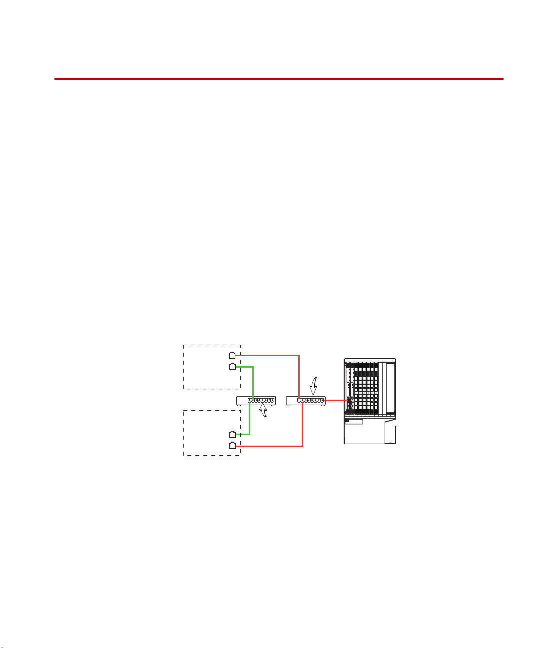
Controller
Network
Controller network–enables your control console electronics to be
shared between all of the PCs.
General data network–enables system software components to be
shared between the Master PC (server) and the dependent PCs (clients).
About the Model 493.04 PC-Per-Station Kit
The Model 493.04 PC-Per-Station Kit allows you to use up to four PCs with one
controller––in effect, you may use one “PC-Per-Station.” This ability to have a
separate computer and monitor for each station simplifies window management
and station operation.
Kit contents The Model 493.04 PC-Per-Station Kit has three variations:
• 2-PC Kit (PN 052-531-501)
Includes: (2) switches, (2) network adapters, (5) 25’ cables
• 3-PC Kit (PN 052-531-502)
Includes: (2) switches, (3) network adapters, (7) 25’ cables
• 4-PC Kit (PN 052-531-503)
Includes: (2) switches, (4) network adapters, (9) 25’ cables
Note These kits do not include PCs. The PC-Per-Station Kit may require
additional customer-supplied network adapters in your computers.
PC-per-station
networks
MTS Model 493.04 PC-Per-Station-Kit
5
Page 6

Network Requirements
Network Requirements
PC Hardware Requirements
Each PC and Ethernet adaptor must meet the following requirements.
PC requirements For current PC requirements, see the “README” file in your current system
controller software folder.
Ethernet adapter
requirements
All Ethernet network interface cards used in each PC must have the TCP and IP
CRC off loading feature, and that feature must be enabled in the driver.
Ethernet Cable Requirements
Cable specifications 10BaseT–at a minimum uses “Category 3.”
100BaseT–at a minimum uses “Category 3.”
100BaseTX–at a minimum uses “Category 5.”
The [nominally] 100 ohm cable impedance should be between 85 and 115 ohms
and have at least two twists per foot. 100Base-TX uses two pairs of Category 5
UTP or two pairs of 150 ohm shielded balanced cable. With 100Base-TX one
wire pair is used for transmission, the other pair for collision detection.
1000Base-T [Gigabit Ethernet]–at minimum uses four-pair Category-5, UTP
[Un-Shielded Twisted Pair] 100-ohm, copper wiring. This is backwards
compatible with 100Base-TX.
PROTOCOL DISTANCE PAIRS REQUIRED CABLE
Meter Half-Duplex Full- Duplex Shielded Twisted Pair (STP)
Unshielded Twisted Pair (UTP)
10Base-T 100 2 STP/UTP
100Base-T 100 2 STP/UTP
100Base-TX 100 2 4 STP/UTP
1000Base-T 100 4 STP/UTP
6
MTS Model 493.04 PC-Per-Station-Kit
Page 7
Network Requirements
Top
Front
1
1
8
8
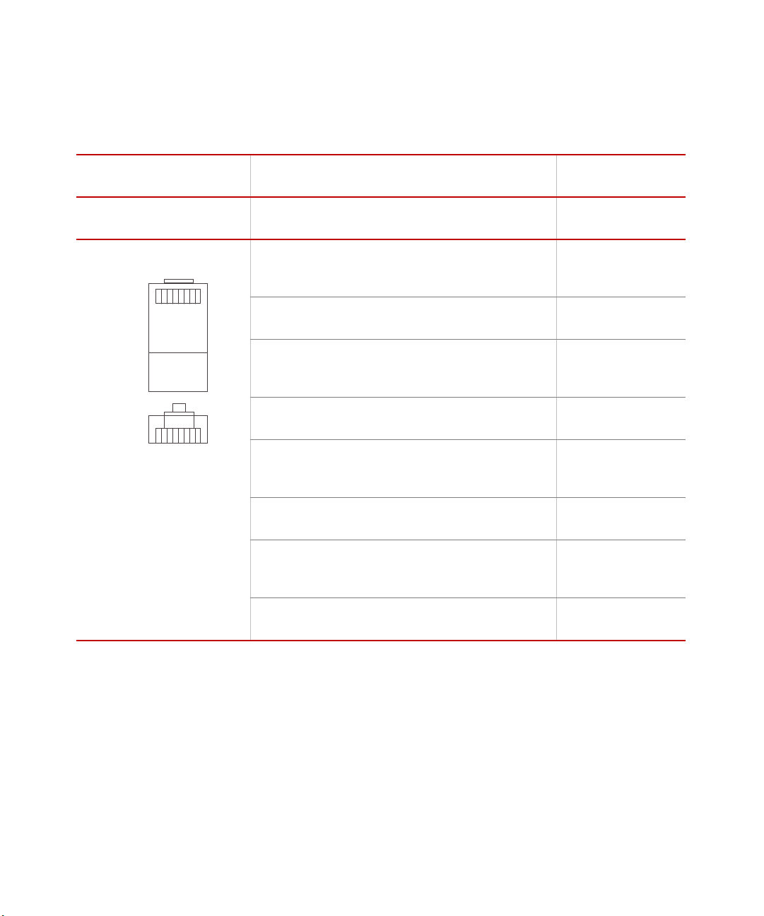
Straight cable pin
assignments
RJ-45
C
ONNECTOR
It is important that each twisted pair is wired as shown in the table below. For
example, TX+ & TX- must be in a pair, and RX+ & RX- must be together in
another pair.
CONNECTOR 1CONNECTOR 2
P
IN NAME DESCRIPTION TIA/EIA
568A
1 TX_D1+ Tranceive
Data+
2 TX_D1- Tranceive
Data-
3 RX_D2+ Receive
Data+
4 BI_D3+ Bi-directional
Data+
5 BI_D3- Bi-directional
Data-
white
and
green
green orange 2 TX_D1-
white
and
orange
blue blue 4 BI_D3+
white
and
blue
TIA/EIA
568B
white
and
orange
white
and
green
white
and
blue
PIN NAME
1 TX_D1+
3 RX_D2+
5 BI_D3-
MTS Model 493.04 PC-Per-Station-Kit
6 RX_D2- Receive
Data-
7 BI_D4+ Bi-directional
Data+
8 BI_D4- Bi-directional
Data-
orange green 6 RX_D2-
white
and
brown
brown brown 8 BI_D4-
white
and
brown
7 BI_D4+
7
Page 8
Network Requirements
Top
Front
1
1
8
8
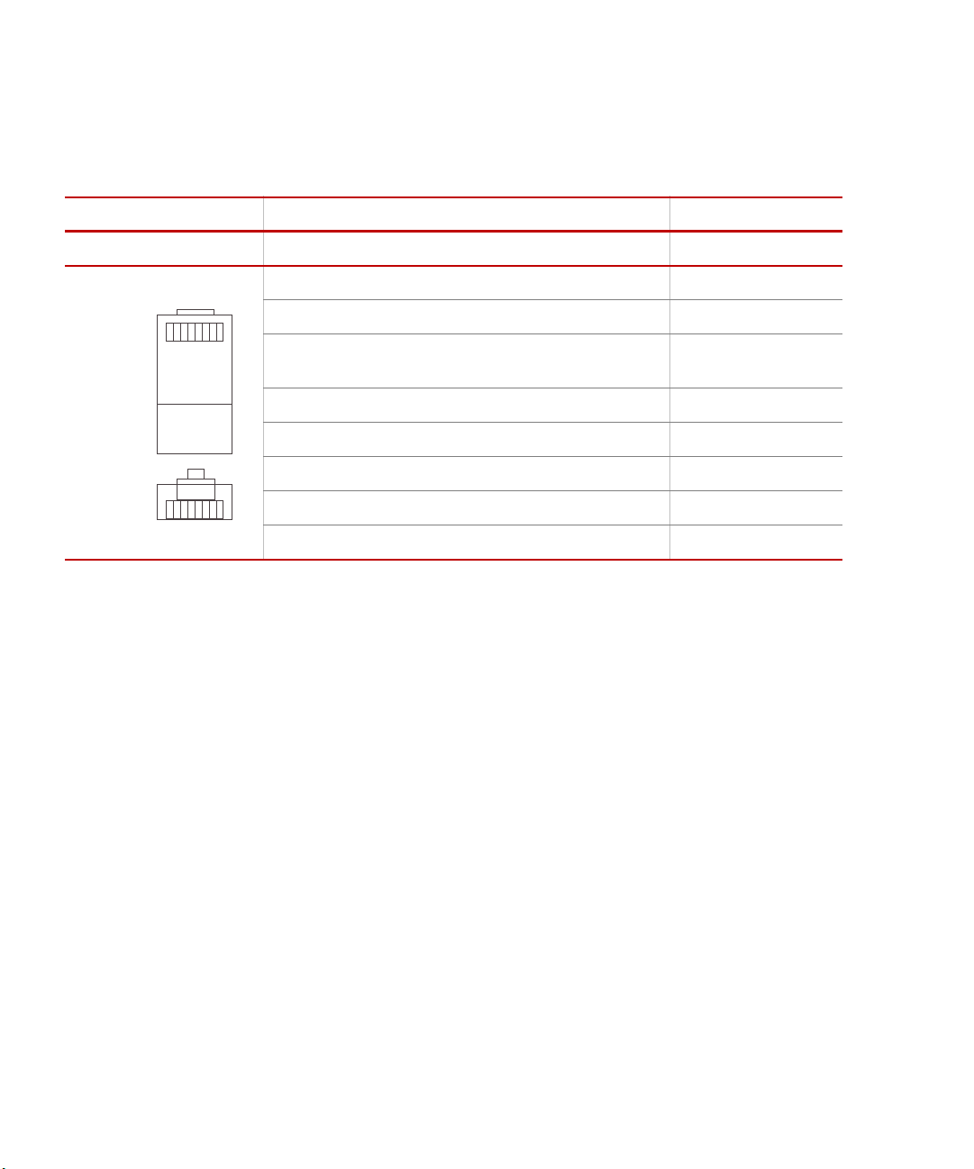
Crossover cable pin
assignments
If a crossover cable is used, you must wire it as shown below. For example, for
568B cable, the white/orange wires connected to Connector 1 pin 1 should go to
Connector 2 pin 3 and Connector 1 pin 2 to Connector 2 pin 6, and so forth.
.
RJ-45 CONNECTOR CONNECTOR 1CONNECTOR 2
IN NAME TIA/EIA 568A TIA/EIA 568B PIN NAME
P
1 TX+ (BI_DA+) white/green white/orange 3 RX+ (BI_DB+)
2 TX- (BI_DA-) green orange 6 RX- (BI_DB-)
3 RX+
(BI_DB+)
4 - (BI_DC+) blue blue 7 - (BI_DD+)
5 - (BI_DC-) white/blue white/blue 8 - (BI_DD-)
6 RX- (BI_DB-) orange green 2 TX- (BI_DA-)
7 - (BI_DD+) white/brown white/brown 4 - (BI_DC+)
8 - (BI_DD-) brown brown 5 - (BI_DC-)
white/orange white/green 1 TX+ (BI_DA+)
8
MTS Model 493.04 PC-Per-Station-Kit
Page 9

Kit Installation Instructions
Kit installation requires an advanced understanding of computer hardware and
networks.
Procedure To install the kit:
1. Install the Network Adapters.
2. Install the Network Switches.
3. Configure PC network connections.
A. Turn on Local Area Connection Properties..
B. Enter the IP address for each network connection.
4. Install MTS Software.
A. Follow the procedure How to Install System Software on the Master
PC on page 16.
B. Follow the procedure How to Install System Client Software on the
Dependent PC(s) on page 17.
Kit Installation Instructions
MTS Model 493.04 PC-Per-Station-Kit
9
Page 10

Install the Network Adapters
Task 1 Install the Network Adapters
How to Install a Network Adapter
See the documentation that came with your network adapter for detailed
hardware installation and configuration instructions.
1. Disconnect power from the PC.
2. Remove the chassis cover from the PC and install the network adapter(s).
3. Replace the chassis cover and apply power to the PC.
4. Install the software drivers required by your network adapter.
Important Configure the network adapter to turn on TCP and IP CRC off
loading feature.
10
MTS Model 493.04 PC-Per-Station-Kit
Page 11

Install the Network Switches
MTS Systems Corp.
14000 Technology Dr.
Eden Prairie, MN 55344-2290 USA
Final Assy No.
Model Serial
1 2 3 4 5 6 7 8 9
10
1
2
3
4
5
6
7
8
1
2
3
4
5
6
7
8
1
2
3
4
5
6
7
8
1
2
3
4
5
6
7
8
1
2
3
4
5
6
7
8
LAN 2 LAN 1
DEBUG
MOTOROLA
10/100 BASE T10/100 BASE T
SCSI
BUSY
PIB
BUSY
PCI MEZZANINE CARD
PCI MEZZANINE CARD
LAN 2 LAN 1
DEBUG
MOTOROLA
10/100 BASE T10/100 BASE T
SCSI
BUSY
PIB
BUSY
PCI MEZZANINE CARD
PCI MEZZANINE CARD
1
2
3
4
5
6
7
8
1
2
3
4
5
6
7
8
Controller
Electronics
Master PC
Dependent PC
Controller Dedicated
Ethernet network adapter
Controller
Dedicated
Network
Switch
General-Data
Network
Switch
Note This drawing shows the 2-PC Kit. To install the 3-PC Kit or 4-PC Kit, install network
adapters in the additional PCs and connect to the network switches as shown.
Controller Dedicated
Ethernet network adapter
General Data Ethernet
Network Adapter
General Data Ethernet
Network Adapter
Task 2 Install the Network Switches
How to Install PC-Per-Station Network Switches
The switches provided with this kit include autodetect features that allow you to
plug MDI or MDIX cables in any of the ports.
Network connections 1. Use an Ethernet cable to connect the controller processor board to the
network switch.
You can use an existing “crossover” cable (MDIX) or one of the straightthrough cables (MDI) provided with the kit.
2. Connect the network switches to the Ethernet network adapters.
3. Attach the “Controller-Dedicated Network” and the “General Data
Network” label to the appropriate network switch.
For more information For detailed cable specifications, see Ethernet Cable Requirements on page 6
MTS Model 493.04 PC-Per-Station-Kit
11
Page 12

Configure PC network connections
Task 3 Configure PC network connections
How to Configure Ethernet Network Connections
Perform this procedure for each Ethernet network adapter.
Note The procedure for entering network IP addresses will vary according to
the Windows operating system you are using.
Note After all the network connections are configured, you may need to reboot
each PC for new assignments to take effect.
1. Turn on Local Area Connection Properties.
A. Apply power to all components.
B. Disable the firewall on the Master PC.
C. Click Start > Settings > Network Connections.
D. Double-click the network connection that you want to configure.
E. Click Properties.
12
MTS Model 493.04 PC-Per-Station-Kit
Page 13

Configure PC network connections
General Data Network Properties
Controller Network Properties
F. In t he Local Area Connection Properties window, select the
following items:
MTS Model 493.04 PC-Per-Station-Kit
2. Enter the IP address for each network connection.
13
Page 14

Configure PC network connections
A. In the Local Area Connection Properties window, select Internet
Protocol (TCP/IP), and click Properties.
B. In the Internet Protocol (TCP/IP) Properties window, enter the IP
address for the network connection. (See the following table for IP
addresses.)
Network Adapter IP Addresses
PC C
IP A
Master PC 148.150.203.190 255.255.255.0 10.0.0.1 255.255.255.0
Dependent A 148.150.203.189 255.255.255.0 10.0.0.2 255.255.255.0
Dependent B 148.150.203.188 255.255.255.0 10.0.0.3 255.255.255.0
Dependent C 148.150.203.187 255.255.255.0 10.0.0.4 255.255.255.0
* If you plan to connect to a corporate network, ask your network administrator for a configuration.
DDRESS SUBNET MASK IP ADDRESS SUBNET MASK
14
ONTROLLER NETWORK GENERAL DATA NETWORK*
MTS Model 493.04 PC-Per-Station-Kit
Page 15

Configure PC network connections
Note The A, B, C designations for dependent PCs are arbitrary. You may
assign any of the listed IP addresses to any of the dependent PCs as
long as each dependent PC has a unique IP address.
AeroPro Network Adapter IP Addresses
PC C
IP A
Server PC 148.150.203.190 255.255.255.0 172.16.20.100 255.255.255.0
Client 1 148.150.203.189 255.255.255.0 172.16.20.101 255.255.255.0
Client 2 148.150.203.188 255.255.255.0 172.16.20.102 255.255.255.0
Client 3 148.150.203.187 255.255.255.0 172.16.20.103 255.255.255.0
DDRESS SUBNET MASK IP ADDRESS SUBNET MASK
ONTROLLER NETWORK AEROPRO LAN
MTS Model 493.04 PC-Per-Station-Kit
15
Page 16

Install MTS Software
Task 4 Install MTS Software
Software Installation Requirements
Simple TCP/IP services, TCP/IP protocol, routing, and real-time logon accounts
must be configured and fully functional. All of the PCs must have the same
Windows operating system (and service pack) installed.
How to Install System Software on the Master PC
1–Install system
software
2–Share the C:\MTS
793 folder on the
Master PC
See the Software Installation Instructions in the “READ ME” file on the 793
System Software Installation CD.
1. Before you begin, ensure that the Master PC Controller Network
connection has an IP address of 148.150.203.190.
2. Install Series 793 application software from the 793 System Software
Installation CD on the Master PC.
Note This typically requires administrator privileges.
Make sure you select the PC-Per-Station option.
From the Master PC, share the System Software folder (C:\MTS 793). and ensure
that Sharing and Security permissions are correct.
1. Right-click the C:\MTS 793 folder and select Properties.
2. Sharing settings–allow Full Control for the Everyone group.
A. Click the Sharing tab, select Share this folder, and then click
Permissions.
B. On the Share Permissions tab, select the Everyone group.
C. For Full Control, select the Allow check box.
3. Security settings–allow Full Control for the SYSTEM group.
16
A. Click the Security tab, and then select SYSTEM group.
B. For Full Control, select the Allow check box.
Note If the Security tab does not appear on the properties window, select
Tools > Folder Options > View. In the Advanced Settings box, clear
the Use simple file sharing check box, and then click Apply. The
Security tab should now appear.
MTS Model 493.04 PC-Per-Station-Kit
Page 17

4. Record the computer name in which you have created the share.
How to Install System Client Software on the Dependent PC(s)
Perform the following procedures to install system client software on each
dependent PC.
Important Do not install system controller software on dependent PCs from
the system software distribution CD. Client software must be
installed over the network using files located on the Master PC.
Install MTS Software
1–Map to the Master
PC shared folder
C:\MTS 793
2–Install client
software over the
network
Map an unused drive letter on the dependent PC to the shared folder on the
Master PC.
1. Before you begin, ensure that each Dependent PC Controller Network
connection has the correct IP address.
2. Open Windows Explorer.
3. On the Too ls menu, select Map Network Drive.
4. From the Folder list, select the name of the shared directory on the Master
PC, for example, “C:\MTS 793”.
Mapping Problems: Make sure that the you map to the correct Master PC
shared path. Also, ensure that Master PC Sharing and Security permissions
for everyone are set to Full Control.
5. Ensure that the Reconnect at Logon box is checked on the Map Network
Drive window.
The client installation application is located in the shared “C:\MTS 793” folder
on the Master PC. Client software is installed over the network.
1. Open the Client folder from the drive you just mapped to the Master PC.
2. Double-click setup.exe to install system client software on your dependent
PC.
3. Select the Full Install option.
MTS Model 493.04 PC-Per-Station-Kit
Dependent PCs automatically acquire the same options as the Master PC.
17
Page 18

How to Use PC-Per-Station Networking
How to Use PC-Per-Station Networking
Basic Operation
The PC-Per-Station Kit links multiple computers to a single controller.
Startup procedure 1. Switch the Master PC on and allow the system to load.
2. Switch the Controller on and allow the system to load.
3. Once the master PC and controller have loaded, you can use dependent
computers to run a test or a simulation.
Typical operation • Multiple users may simultaneously run different tests (at individual
stations) through a single controller.
• You can still control multiple stations from any individual PC if
desired.
Simulation mode You can run in the simulation mode on one computer without affecting any other
computer on the network.
Note Do not run a simulation and a real session on a single computer.
PC-Per-Station Troubleshooting
Master PC The master PC is the network server for the controller software.
• System software must be installed on the master PC.
• Network adapters must be installed and all network connections configured.
• IP addresses for the controller and General network adapters must be
correct.
• The firewall must be disabled to allow communications from the controller.
Dependent PCs • Each dependent PC must have controller client software installed.
• Each dependent computer must have a drive mapped to the master PC
C:\MTS 793 folder. Make sure that Reconnect at login is enabled.
18
MTS Model 493.04 PC-Per-Station-Kit
Page 19

How to Use PC-Per-Station Networking
12345678
MDIX
Switch
Port 8 To controller processor
Ports 1-7 To built-in PC Ethernet connectors
About Older PC-Per-Station Installations with Network Hubs
Older PC-Per-Station installations use a network hub configured as shown below.
Note Hubs only support hal-duplex communications.
1. Use the existing “crossover” cable to connect the controller processor
module to the Uplink/Normal (MDI/MDIX) port (usually port 8) of the
controller-dedicated network hub.
The Uplink/Normal (MDI/MDIX) port LED (usually port 8) should
illuminate when the connection has been established. If the LED does not
illuminate, press the Uplink/Normal (MDI/MDIX) port switch located on
the back of the hub.
2. Connect the controller-dedicated network hub to the built-in Ethernet
Note Make sure everyone using your system controller can identify the master
MTS Model 493.04 PC-Per-Station-Kit
network adapters in the PCs.
PC. You must apply power to the master PC to use controller software
applications on the dependent PCs.
19
Page 20

How to Use PC-Per-Station Networking
20
MTS Model 493.04 PC-Per-Station-Kit
Page 21

Index
Numerics
1000Base-T cable specifications 6
100BaseT cable specifications 6
100BaseTX cable specifications 6
10BaseT cable specifications 6
A
AeroPro network adapter IP Address 15
C
Cable specifications 6
Configure ethernet network connections 12
Controller network 5
Controller network properties 13
Crossover cable pin assignments 8
D
Dependent PC 11
G
General data ethernet network adapter 11
General data network 5
General data network properties 13
H
Half-duplex 6
I
Install PC-Per-Station network switches 11
Install system software on the master PC 16
K
Kit contents 5
Kit installation 9
M
E
Ethernet adapter requirements 6
Ethernet cable requirements 6
Master PC 11
MDI cables 11
MDIX cables 11
Model 493.04 PC-Per-Station Kit 5
N
F
Full- duplex 6
MTS Model 493.04 PC-Per-Station-Kit Index
Network adapter IP address 14
Network connections 11
Network switches 11
21
Page 22

O
Old PC-Per-Station installations with network hubs 19
P
PC requirements 6
PC-Per-Station Kit 5
PC-Per-Station network switches 11
PC-Per-Station Networking 18
PC-Per-Station Networks 5
PC-Per-Station Troubleshooting 18
PC-Per-Station troubleshooting 18
pin assignments 7, 8
R
RX- pin assignments 7
RX+ pin assignments 7
S
Security settings 16
Sharing settings 16
Straight cable pin assignments 7
T
TCP and IP CRC off loading feature 6
TX- pin assignments 7
TX+ pin assignments 7
Index
22
MTS Model 493.04 PC-Per-Station-Kit
Page 23

Page 24

m
MTS Systems Corporation
14000 Technology Drive
Eden Prairie, Minnesota 55344-2290 USA
Toll Free Phone: 800-328-2255
(within the U.S. or Canada)
Phone: 952-937-4000
(outside the U.S. or Canada)
Fax: 952-937-4515
E-mail: info@mts.com
Internet: www.mts.com
ISO 9001 Certified QMS
 Loading...