


XT1225/XT1254
BASEBAND TROUBLESHOOTING GUIDE
Sept 18, 2014
Motorola Mobility Confidential Proprietary

TABLE OF CONTENTS
1. Snapshots of Antennas ………………………..………………….………………………..... 3 2. Snapshots/plots of Main Board .….…………….……………….………………..…………. 5 3. Touch Troubleshooting……………...…….………………….……………………..……….. 9 4. Display Troubleshooting…………….…….………………………………………..…….…. 15 5. Audio Troubleshooting……………………………………………………………………….. 21 6. No Power up Troubleshooting………………………………………………………………. 34 7. Battery & Charger Troubleshooting……………………………………….………………... 47 8. Sensors and SIM Troubleshooting …..……………………………………..……………… 55 9. Camera Troubleshooting…………………………………………………………………….. 66 10. BT & WiFi Troubleshooting……………………………………………………………………80 11. NFC Troubleshooting……………………………………………………………….…………92
Motorola Mobility Confidential Proprietary |
Sept 18, 2014 |
Page 2 |

SNAPSHOTS OF ANTENNAS
Motorola Mobility Confidential Proprietary |
Sept 18, 2014 |
Page 3 |
Antenna
Motorola Mobility Confidential |
Sept 18, |
Page 4 |

SNAPSHOTS/PLOTS OF MAIN BOARD
Motorola Mobility Confidential Proprietary |
Sept 18, 2014 |
Page 5 |
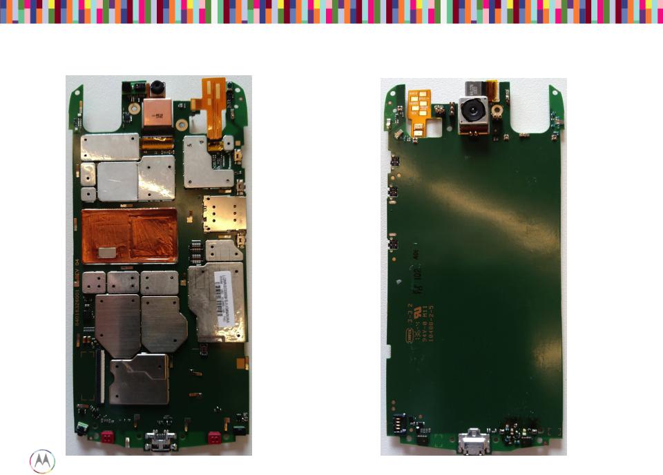
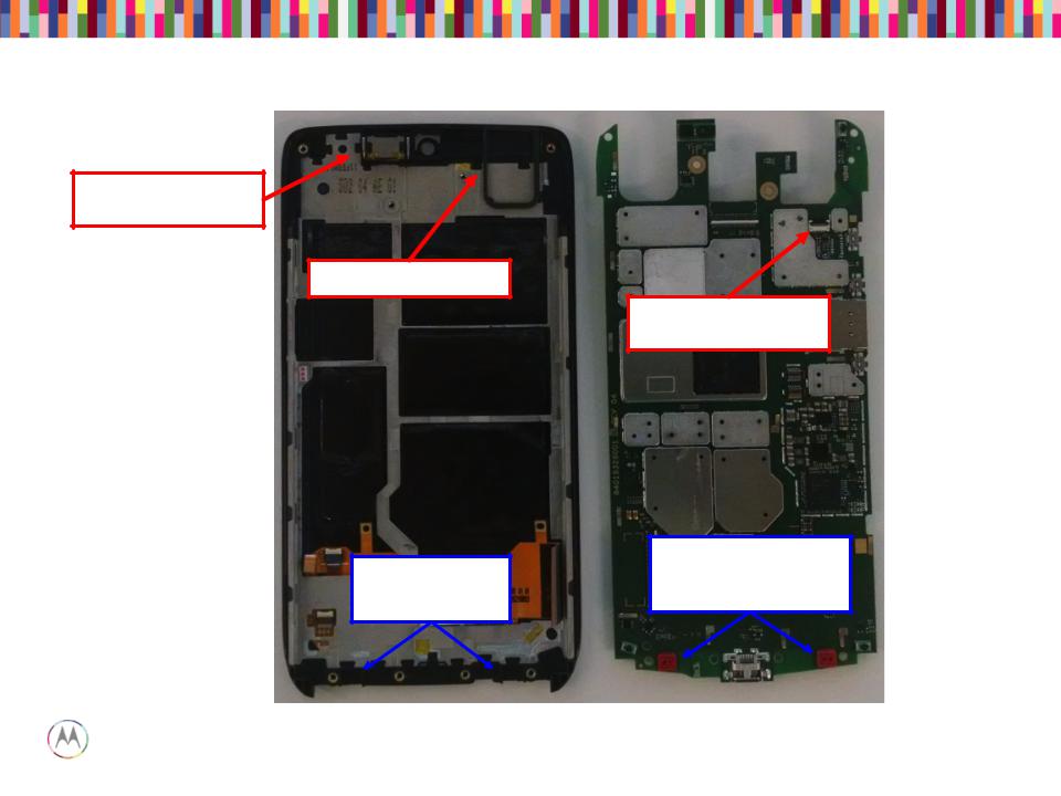
Snapshots of Main PCB
Top Side (Display) Bottom Side (Battery)
Motorola Mobility Confidential Proprietary |
Sept 18, 2014 |
Page 6 |

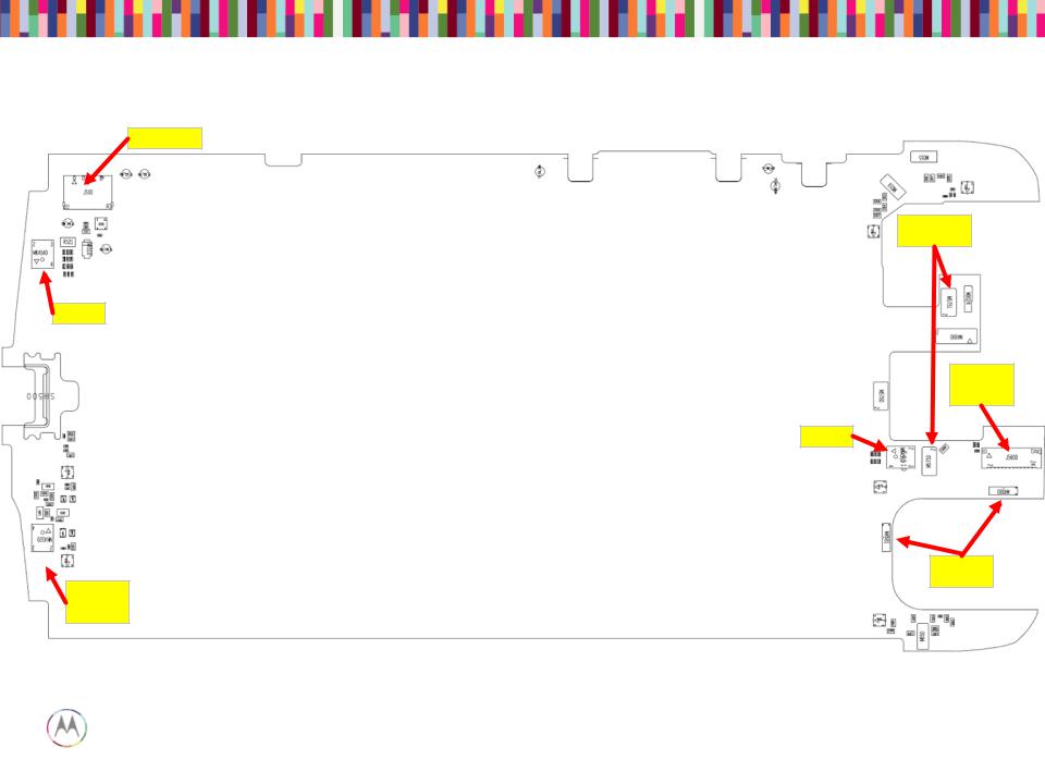
TFA9890
MMPA
TMS320C5545
WCD9320
RFFE
QCA6164
Headset /
Socket
SMB1359
4
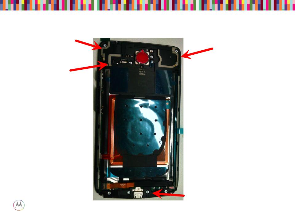
Main Board – Bottom Placement
Battery Con.
MIC 3
Front
ZIF
MIC 5 (not used)
Mobility Confidential Proprietary |
Sept 18, 2014 |

TOUCH TROUBLESHOOTING
Motorola Mobility Confidential Proprietary |
Sept 18, 2014 |
Page 9 |
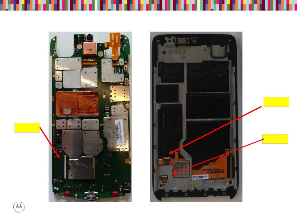
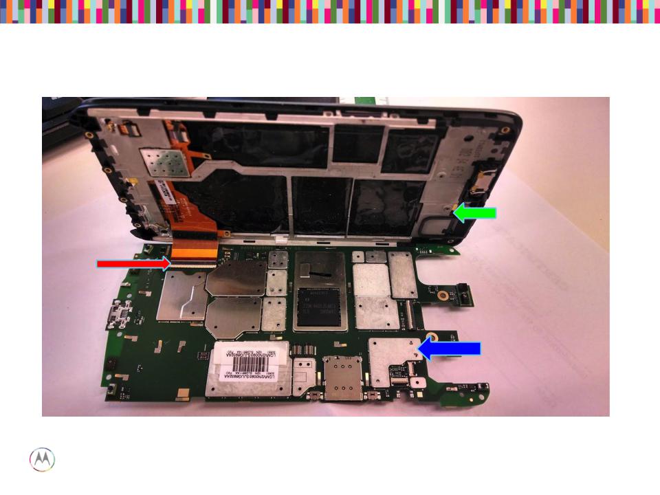
Main Board – Location of LCD |
ZIF connectors |
Touch ZIF
Display ZIF
TSB ZIF
Motorola Mobility Confidential Proprietary |
Sept 18, 2014 |
Capacitive Touch Block Diagram
Motorola Mobility Confidential Proprietary |
Sept 18, 2014 |
Page 11 |
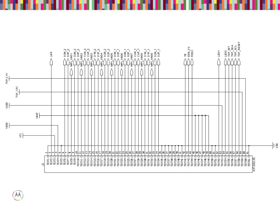
Display/Touch Connector
Motorola Mobility Confidential Proprietary |
Sept 18, 2014 |
Page 12 |
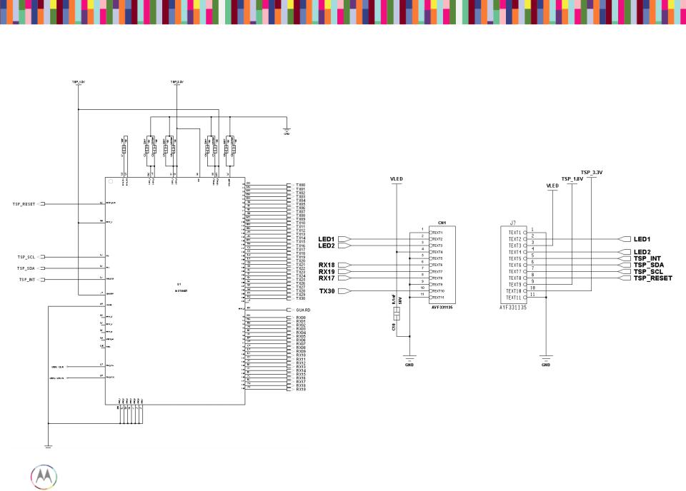
Touch IC Schematic
Motorola Mobility Confidential Proprietary |
Sept 18, 2014 |
Page 13 |

Touch Troubleshooting
1. No Touch response when display touched
• Swap display panels with known good panel. If touch works, problem with display flex or IC (Go to 3). If still not working, problem with main board (Go to 2).
2. Main Board Issue
• Check touch connector for proper insertion of flex.
• Ensure 3.2VDC power is at the display ZIF.
• Verify Reset signal is high, IRQ is high.
• I2C Data and I2C Clock at 1.8VDC.
3. Display panel issue
• Check Touch flex for any damage.
• Ensure 3.2VDC and 1.8 VDC supplies are at the touch ZIF.
• Verify Reset signal is high, IRQ is high, I2C Data and Clock at 1.8VDC.
• When touching panel, INT should toggle low, I2C data and clk will toggle.
Motorola Mobility Confidential Proprietary |
Sept 18, 2014 |
Page 14 |

DISPLAY TROUBLESHOOTING
Motorola Mobility Confidential Proprietary |
Sept 18, 2014 |
Page 15 |

Display
• This display is a color Active Matrix Organic Light Emitting Diode (AMOLED) of glass construction with White pixels on a Black background.
• The display consists of high density pixels with a color depth of 16.7M colors (24 bpp). The display interface is two MIPI DSI ports MIPI in command mode.
• Chip-on-glass (COG) with the driver located at bottom front of panel.
• 2 LEDs on flex for android key backlighting.
• Display operates in MIPI command mode with onboard RAM.
Motorola Mobility Confidential Proprietary |
Sept 18, 2014 |
Page 16 |
Assembly
Display Module
61-pin display ZIF connector
Main PCB
Motorola Mobility Confidential Proprietary |
Sept 18, 2014 |
Page 17 |
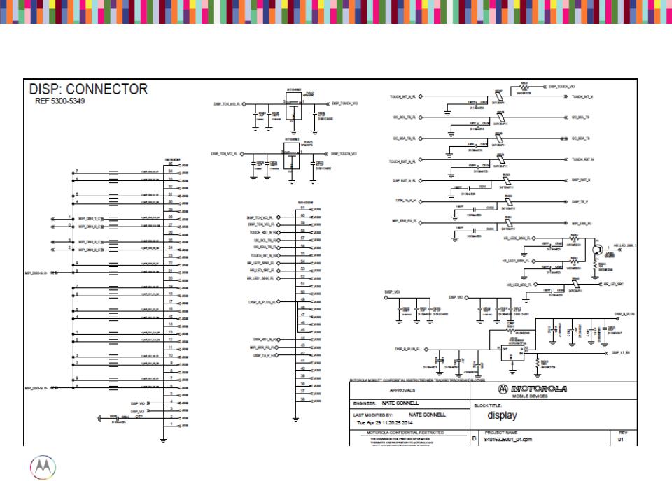
Display Main Schematic
Motorola Mobility Confidential Proprietary |
Sept 18, 2014 |
Page 18 |
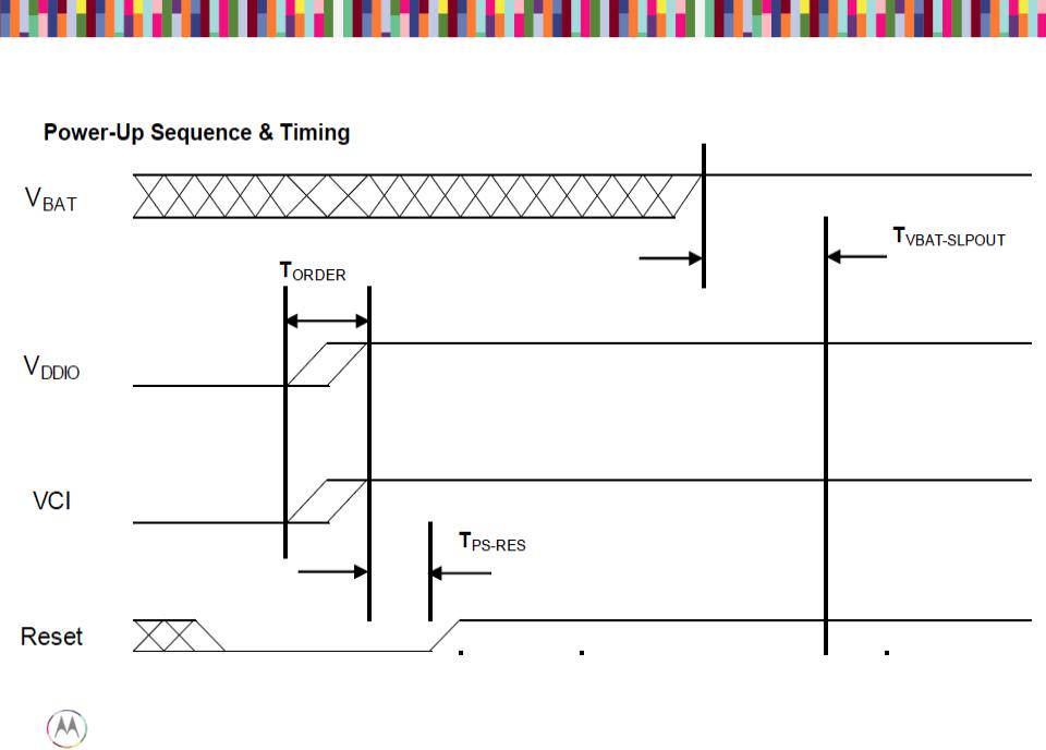
Power-up Sequence
Pin45~49 of J5300; Vbat from C5314
Pin4 of J5300; Vddio from C5317
Pin3 of J5300; Vddio from C5320
Pin44 of J5300; RST from E5333
Motorola Mobility Confidential Proprietary |
Sept 18, 2014 |
Page 19 |

Display Troubleshooting
• Check 61pin display ZIF connector 1. Properly inserted
2. Any damage to ZIF receptacle on main PCB or plug on disp flex tail 3. Swap in known good main PCB or good disp module to see if issue
follows main PCB or display flex
• If the issue follows main PCB
1. Check DISP_B_PLUS (Vbat) voltage (3.15 to 4.4VDC) at Pin45~49 of J5300
2. Check DISP_VIO voltage (1.8VDC) at Pin4 of J5300 3. Check DISP_VCI voltage (3.1VDC) at Pin3 of J5300
4. Check above 3 voltages after phone power up. If they are not turned on, check them during phone power up.
• If the issue follows display module, replace the module.
Motorola Mobility Confidential Proprietary |
Sept 18, 2014 |
Page 20 |
AUDIO TROUBLESHOOTING
Motorola Mobility Confidential Proprietary |
Sept 18, 2014 |
Page 21 |

Audio Devices
Tertiary Microphone
Port
Quinary Microphone
Port
Audio Devices (PCB View)
Earpiece speaker (32 ohms)
Loudspeaker Gasket
Quarternary (right)
mic & grommets
Motorola Mobility Confidential |
18, 2014 |
Page 23 |
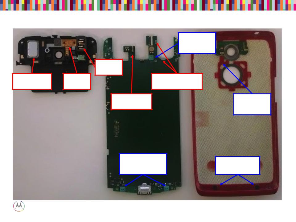
Audio Devices (PCB View)
Secondary
Headset
Jack
Earpiece
Mesh Assembly
24

CQA Application
• Launching the CQA app will help resolve and root-cause the vast majority of problems
• Go to the phone/dialer and enter *#*#2486#*#*
• The CQA main menu will pop-up – select “Start CQA Test in Menu Mode”
• Select the appropriate debug area – for Audio, primarily you will use AUDIO and HEADSET
• The AUDIO CQA area has test capability for both mics, earpiece and loudspeaker
• The HEADSET CQA area should be used to debug any detection, or lack of audio on the headset jack path
Motorola Mobility Confidential Proprietary |
Sept 18, 2014 |
Page 25 |

“No Audio” Complaints
• The CQA apk can be used to verify a broken audio path. Under the “Audio” menu, select “Mic Loopback”.
– The “PRIMARY MIC” setting allows a mic1 to earpiece loopback (recommended)
• Note* - The “DEFAULT MIC” setting also allows this, if a headset device is not plugged in.
– The “SECONDARY MIC” setting loops mic2 to the earpiece, and so on.
– *NOTE* The “SECONDARY MIC LPA” path does not exist in HW and will not loopback any audio.
• If both of those are not functional, the earpiece speaker path is likely damaged. In the “AUDIO” menu of the CQA apk, select “Ear Speaker” and then “Play Harvard speech pattern” and/or “Buzz Sweep”.
• The loudspeaker can be tested by selecting “Loudspeaker” via the CQA apk. A musical composition should start playing and be easily heard.
• If audio is not present on the HEADSET path, select the “Headset” entry in the main menu of the CQA app, then plug-in the headset device to view whether the lack of audio is a detection-cycling issue or other anomaly.
Motorola Mobility Confidential Proprietary |
Sept 18, 2014 |
Page 26 |
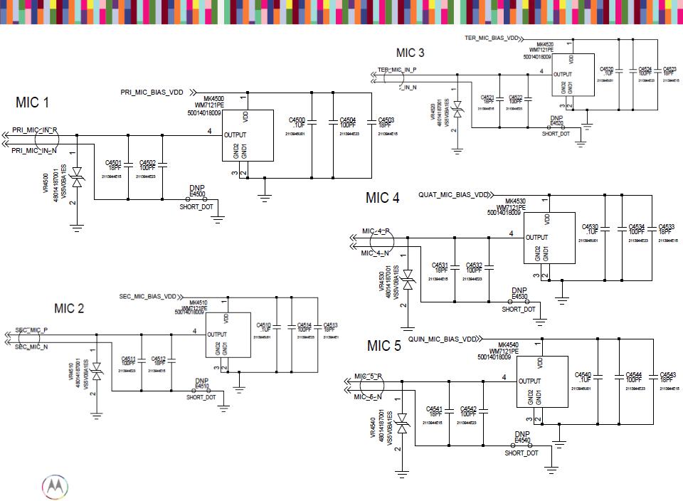
Microphones
Motorola Mobility Confidential Proprietary |
Sept 18, 2014 |
Page 27 |

Microphones Troubleshooting
If a mic is not functioning…
• Check to make sure the microphone and mic ports are not blocked.
• Check to make sure the mic gasket and mic grommets are seated properly.
• Check the microphone for diaphragm debris indicating a shattered diaphragm. Look under a microscope to view inside the microphone port for damage or debris.
• Check to make sure none of the capacitors on the mic lines are shorted or damaged.
• Check the mic bias C4500 (Mic1), C4510 (Mic2), C4520 (Mic3), C4530 (Mic4), C4540 (Mic5). The mic bias should be 2.8V when the microphone is enabled.
• If the failure is no microphone audio, check mic loopback through CQA at the board level with a display connected. (Mic loopback may be easier to check with a headset plugged in)
• If there is no audio during mic loopback, inject a 35mVrms, 1kHz sine wave onto the MIC_IN_P side of C4501 (Mic1), C4511 (Mic2), C4521 (Mic3), C4531 (Mic4), C4541 (Mic5) and listen for the tone during loopback. If you can hear the tone now, you know either the mic is bad, or there’s a process defect with the mic-to-PCB connection.
• X-ray the mic to check for process defects.
• If there is an issue with Mic5 LPA path, also check U6281 and the components around it for process defects.
Motorola Mobility Confidential Proprietary |
Sept 18, 2014 |
Page 28 |
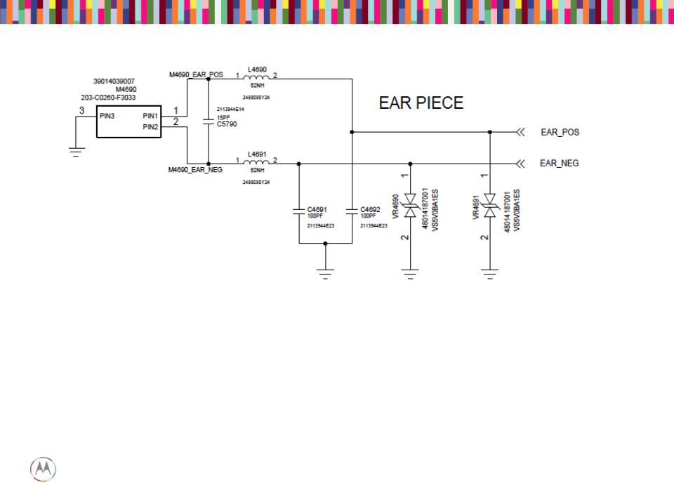
Earpiece Speaker (Handset Mode DOWNLINK)
• Check that the impedance of the earpiece speaker is 32 ohms, and that the spring contacts are not bent.
• Check that the earpiece flex is seated properly in the top carrier with no debris on it. You should also be able to see slight imprints in the gold pads where both the speaker contacts and PCB pogo contacts were touching the flex.
• Check that the earpiece pogo connector on the PCB is seated properly with no bent or stuck pogos.
• Check that L4690 and L4691 are not damaged or skewed. Also check C4691, C4692, C5790, VR4690 and CR4691 for any placement issues.
Motorola Mobility Confidential Proprietary |
Sept 18, 2014 |
Page 29 |
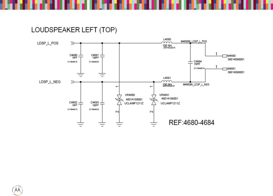
Loudspeaker
• Verify the impedance of the loudspeaker is 8 ohms.
• Verify the loudspeaker gasket is placed correctly.
• Lack of mechanical contact should also be checked (bent loudspeaker pins on PCB).
• Make sure L4680 and L4681 are not skewed or damaged.
• Check C4684, C4680, C4681, C4682, C4683, VR4680, and VR4681 for any placement issues.
Motorola Mobility Confidential Proprietary |
Sept 18, 2014 |
Page 30 |
 Loading...