


ASTRO® XTSTM 2500
Digital Portable Radio
Model I
User Guide
ASTRO® XTS™ 2500
Digital Portable Radio, Model I
Quick Reference Card
Product Safety and RF Exposure Compliance
! |
Before using this product, read the operating instructions |
for safe usage contained in the Product Safety and RF |
|
C a u t i o n |
Exposure booklet enclosed with your radio. |
ATTENTION!
This radio is restricted to occupational use only to satisfy FCC RF energy exposure requirements. Before using this product, read the RF energy awareness information and operating instructions in the Product Safety and RF Exposure booklet enclosed with your radio (Motorola Publication part number 6881095C98) to ensure compliance with RF energy exposure limits.
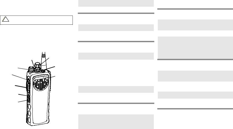
3-Position |
16-Position |
|
Rotary Switch |
||
_ _ _ _ _ _ |
Select Knob |
|
On/Off/ |
Top Button |
|
Volume Knob |
||
_ _ _ _ _ _ _ |
||
|
||
Top Side |
Speaker/Mic |
|
Button |
||
|
||
_ _ _ _ _ _ _ |
|
|
PTT Button |
|
|
Side Button 1 |
|
|
_ _ _ _ _ _ _ |
|
|
Side Button 2 |
|
|
_ _ _ _ _ _ _ |
|
Write your radio’s programmed features on the dotted lines.
Radio On/Off
1On - On/Off/Volume knob clockwise.
2Off - On/Off/Volume knob counterclockwise.
Zones/Channels
1Zone - Move Zone switch to desired zone.
2Channel - Turn Channel Selector switch to desired channel.
Receive/Transmit
1Radio on and select zone/channel.
2Listen for a transmission.
OR
Press and hold Volume Set button. Release
Volume Set button.
OR
Press Monitor button and listen for activity.
3Adjust volume, if necessary.
4Press and hold PTT to transmit; release to listen.
Send Emergency Alarm
1Radio on and press Emergency button. You see red LED; you hear short, medium-pitched tone.
2When dispatcher’s acknowledgment is received, you hear four tones; alarm ends; radio exits emergency.
Send Silent Emergency Alarm
1Radio on and press Emergency button. You see no LED; you hear no tone.
2Press PTT.
3Alarm continues until you exit by:
• Press and hold Emergency button for one
second
OR
•Press and release PTT.
Send Emergency Call
1Radio on and press Emergency button. A short, medium-pitched tone sounds.
2Press and hold PTT. Announce your emergency into the microphone.
3Release PTT to end call.
4Press and hold Emergency button for one second to exit.

ASTRO® XTS™ 2500
Digital Portable Radio
Model I
User Guide
6881094C04-D
MOTOROLA, the Stylized M Logo, ASTRO, and CommPort are registered in the U.S. Patent & Trademark Office. All other product or service names are the property of their respective owners.
P25 radios contain technology patented by Digital Voice Systems, Inc. © Motorola, Inc. 2004. All Rights Reserved. Printed in the U.S.A. 10/4/04.
Motorola, Inc.
8000 W. Sunrise Blvd.
Ft. Lauderdale, FL 33322
i

This declaration is applicable to your radio only if your radio is labeled with the FCC logo shown below.
DECLARATION OF CONFORMITY
Per FCC CFR 47 Part 2 Section 2.1077(a)
Responsible Party Name: Motorola, Inc.
Address: 8000 West Sunrise Boulevard Plantation, FL 33322 USA
Phone Number: 1-888-567-7347 Hereby declares that the product:
Model Name: XTS 2500 conforms to the following regulations:
FCC Part 15, subpart B, section 15.107(a), 15.107(d) and section 15.109(a)
Class B Digital Device
As a personal computer peripheral, this device complies with Part 15 of the FCC Rules. Operation is subject to the following two conditions:
1.this device may not cause harmful interference, and
2.this device must accept any interference received, including interference that may cause undesired operation.
Note: This equipment has been tested and found to comply with the limits for a Class B digital device, pursuant to part 15 of the FCC Rules. These limits are designed to provide reasonable protection against harmful interference in a residential installation. This equipment generates, uses and can radiate radio frequency energy and, if not installed and used in accordance with the instructions, may cause harmful interference to radio communications. However, there is no guarantee that interference will not occur in a particular installation.
If this equipment does cause harmful interference to radio or television reception, which can be determined by turning the equipment off and on, the user is encouraged to try to correct the interference by one or more of the following measures:
•Reorient or relocate the receiving antenna.
•Increase the separation between the equipment and receiver.
•Connect the equipment into an outlet on a circuit different from that to which the receiver is connected.
•Consult the dealer or an experienced radio/TV technician for help.
ii
Product Safety and RF Exposure Compliance
Before using this product, read the operating
!instructions for safe usage contained in the Product
C a u t i o n Safety and RF Exposure booklet enclosed with your radio.
ATTENTION!
This radio is restricted to occupational use only to satisfy FCC RF energy exposure requirements. Before using this product, read the RF energy awareness information and operating instructions in the Product Safety and RF Exposure booklet enclosed with your radio (Motorola Publication part number 6881095C98) to ensure compliance with RF energy exposure limits.
For a list of Motorola-approved antennas, batteries, and other accessories, visit the following web site which lists approved accessories: http://www.motorola.com/cgiss/index.shtml
Computer Software Copyrights
The Motorola products described in this manual may include copyrighted Motorola computer programs stored in semiconductor memories or other media. Laws in the United States and other countries preserve for Motorola certain exclusive rights for copyrighted computer programs, including, but not limited to, the exclusive right to copy or reproduce in any form the copyrighted computer program. Accordingly, any copyrighted Motorola computer programs contained in the Motorola products described in this manual may not be copied, reproduced, modified, reverseengineered, or distributed in any manner without the express written permission of Motorola. Furthermore, the purchase of Motorola products shall not be deemed to grant either directly or by implication, estoppel, or otherwise, any license under the copyrights, patents or patent applications of Motorola, except for the normal non-exclusive license to use that arises by operation of law in the sale of a product.
Documentation Copyrights
No duplication or distribution of this document or any portion thereof shall take place without the express written permission of Motorola.
iii
No part of this manual may be reproduced, distributed, or transmitted in any form or by any means, electronic or mechanical, for any purpose without the express written permission of Motorola.
Disclaimer
The information in this document is carefully examined, and is believed to be entirely reliable. However, no responsibility is assumed for inaccuracies. Furthermore, Motorola reserves the right to make changes to any products herein to improve readability, function, or design. Motorola does not assume any liability arising out of the applications or use of any product or circuit described herein; nor does it cover any license under its patent rights, nor the rights of others.
iv

Contents
Declaration of Conformity .................................................................. |
ii |
Product Safety and RF Exposure Compliance ................................. |
iii |
Computer Software Copyrights ......................................................... |
iii |
Documentation Copyrights ................................................................ |
iii |
Disclaimer ........................................................................................ |
iv |
General Radio Operation.............................................. |
1 |
Notations Used in This Manual ......................................................... |
1 |
XTS 2500 Model I Radio ................................................................... |
2 |
Physical Features of the XTS 2500 Model I Radio ........................... |
3 |
Programmable Features ................................................................... |
4 |
LED Indicators .................................................................................. |
5 |
Alert Tones ........................................................................................ |
5 |
Standard Accessories ....................................................................... |
8 |
Battery ........................................................................................ |
8 |
Antenna .................................................................................... |
10 |
Belt Clip .................................................................................... |
11 |
Universal Connector Cover ............................................................. |
12 |
Remove the Connector Cover .................................................. |
12 |
Attach the Connector Cover ..................................................... |
12 |
Remote Speaker Microphone Adapter ............................................ |
13 |
Remove the Adapter ................................................................. |
13 |
Attach the Adapter .................................................................... |
13 |
Radio On and Off ............................................................................ |
14 |
Turn the Radio On .................................................................... |
14 |
Turn the Radio Off .................................................................... |
14 |
Zones and Channels ....................................................................... |
15 |
Select a Zone ........................................................................... |
15 |
Select a Channel ..................................................................... |
15 |
Receive / Transmit .......................................................................... |
16 |
Without Using the Volume Set and Monitor Buttons ................ |
16 |
Use the Preprogrammed Volume Set Button ........................... |
17 |
Use the Preprogrammed Monitor Button .................................. |
18 |
Conventional Mode Operation ........................................................ |
19 |
Common Radio Features............................................ |
21 |
Selectable Power Level ................................................................... |
21 |
Conventional Squelch Options ........................................................ |
21 |
Analog Squelch ........................................................................ |
21 |
ASTRO XTS 2500 Model I |
v |

PL Defeat ......................................................................................... |
21 |
Time-out Timer ................................................................................ |
22 |
Emergency ...................................................................................... |
23 |
Send an Emergency Alarm ....................................................... |
24 |
Send a Silent Emergency Alarm ............................................... |
25 |
Send an Emergency Call .......................................................... |
25 |
Emergency Keep-Alive ............................................................. |
27 |
Scan ................................................................................................ |
28 |
Turn Scan On and Off ............................................................... |
28 |
Delete a Nuisance Channel ...................................................... |
28 |
Conventional Scan Only ........................................................... |
29 |
Telephone Calls (Trunking Only) ..................................................... |
30 |
Answer a Phone Call ................................................................ |
30 |
Private Calls (Trunking Only) ........................................................... |
31 |
Answer a Private Call ................................................................ |
31 |
Call Alert Paging .............................................................................. |
32 |
Answer a Call Alert Page .......................................................... |
32 |
Repeater or Direct Operation .......................................................... |
33 |
Select Repeater or Direct Operation ........................................ |
33 |
Special Radio Features ............................................... |
35 |
Trunking System Controls ............................................................... |
35 |
Failsoft ...................................................................................... |
35 |
Out-of-Range ............................................................................ |
35 |
Site Lock ................................................................................... |
36 |
Site Change .............................................................................. |
36 |
Helpful Tips .................................................................. |
37 |
Radio Care ...................................................................................... |
37 |
Cleaning .................................................................................... |
37 |
Handling .................................................................................... |
37 |
Service ............................................................................................. |
38 |
Battery ............................................................................................. |
39 |
Battery Life ................................................................................ |
39 |
Charging the Battery ................................................................. |
39 |
Battery Recycling and Disposal ....................................................... |
40 |
Antenna ........................................................................................... |
41 |
Radio Operating Frequencies ................................................... |
41 |
vi
Accessories ................................................................. |
43 |
Antennas ......................................................................................... |
43 |
Batteries .......................................................................................... |
43 |
Carry Accessories ........................................................................... |
44 |
Belt Clips .................................................................................. |
44 |
Body-Worn ................................................................................ |
44 |
Chargers ......................................................................................... |
44 |
Enhanced and Multi-Unit Line Cords ........................................ |
45 |
Microphones, Remote Speaker ....................................................... |
45 |
Surveillance Accessories ................................................................ |
46 |
Adapters and Adapter Cable .................................................... |
46 |
CommPort® Integrated Microphone/Receivers ........................ |
46 |
Earpieces .................................................................................. |
46 |
Headsets and Headset Accessories ......................................... |
47 |
Radio Interface Modules for Ear Microphones ......................... |
48 |
Switches .......................................................................................... |
48 |
Appendix: Maritime Radio Use in the |
|
VHF Frequency Range................................................ |
49 |
Special Channel Assignments ......................................................... |
49 |
Emergency Channel ................................................................. |
49 |
Non-Commercial Call Channel ................................................. |
50 |
Operating Frequency Requirements ............................................... |
50 |
Glossary....................................................................... |
53 |
Commercial Warranty ................................................. |
57 |
Index............................................................................. |
63 |
ASTRO XTS 2500 Model I |
vii |
viii
Table 1: Channel Map
Use the chart below to map the channels (Cx) and zones (Zx) for your radio.
Z1 |
Z2 |
Z3 |
Z4 |
Z5 |
Z6 |
C1
C2
C3
C4
C5
C6
C7
C8
C9
C10
C11
C12
C13
C14
C15
C16
General Radio Operation
Notations Used in This Manual
You will notice the use of WARNINGS, CAUTIONS, and Notes throughout this manual. These notations are used to emphasize that safety hazards exist and that care must be taken or observed.
An operational procedure, practice, condition,
!etc. exists which may result in injury or death if not carefully observed.
W A R N I N G
An operational procedure, practice, condition, etc.
!exists which may result in damage to the equipment if not carefully observed.
C a u t i o n
Note: An operational procedure, practice, or condition, etc. which is essential to emphasize.
The following special notations identify certain items:
Example |
Description |
|
|
Top button |
Buttons are shown in bold print. |
|
|
ASTRO XTS 2500 Model I |
1 |

General Radio Operation
XTS 2500 Model I Radio
6
7
8
9
10
11
12
13
14
1
2
3
4
5
2

General Radio Operation
Physical Features of the XTS 2500 Model I Radio
|
Item |
Page |
|
Item |
Page |
|
|
|
|
|
|
1 |
Antenna |
10 |
8 |
On/Off/Volume |
14 |
|
|
|
|
Control Knob |
|
|
|
|
|
|
|
2 |
Top Button |
|
9 |
Microphone |
|
|
(programmable) |
|
|
|
|
|
|
|
|
|
|
3 |
LED |
5 |
10 |
Top Side (Select) |
|
|
|
|
|
Button |
|
|
|
|
|
(programmable) |
|
|
|
|
|
|
|
4 |
Speaker |
|
11 |
Push-to-Talk |
|
|
|
|
|
(PTT) Button |
|
|
|
|
|
|
|
5 |
Universal Connector |
12 |
12 |
Side Button 1 |
|
|
|
|
|
(programmable) |
|
|
|
|
|
|
|
6 |
16-Position Knob |
|
13 |
Side Button 2 |
|
|
(programmable) |
|
|
(programmable) |
|
|
|
|
|
|
|
7 |
3-Position Concentric |
|
14 |
Battery |
8 |
|
Switch (programmable) |
|
|
|
|
|
|
|
|
|
|
ASTRO XTS 2500 Model I |
3 |

General Radio Operation
Programmable Features
The programmable controls on your radio can be programmed by a qualified technician to operate certain software-activated features. The features that can be assigned to these controls, and the page numbers where these features can be found, are listed below.
Table 1: Programmable Features
Feature |
Page |
Feature |
Page |
|
|
|
|
Call Response |
30 |
Repeater/Direct |
33 |
|
|
|
|
Channel Selection |
15 |
Scan On/Off |
28 |
|
|
|
|
Dynamic Priority |
29 |
Site Lock/Unlock |
36 |
|
|
|
|
Emergency |
23 |
Site Search |
36 |
|
|
|
|
Monitor |
18 |
Transmit Power Level |
21 |
|
|
|
|
Nuisance Delete |
28 |
Volume Set |
17 |
|
|
|
|
Phone |
30 |
Zone Selection |
15 |
|
|
|
|
PL Defeat |
21 |
|
|
|
|
|
|
Any references in this manual to controls that are “preprogrammed” means that a qualified radio technician must use the radio’s programming software to assign a feature to a control.
4
|
|
General Radio Operation |
|
|
|
LED Indicators |
|
|
|
Table 2: LED Indicators |
|
|
|
|
This LED Color: |
|
indicates: |
|
|
|
RED (Non-flashing) |
|
Transmitting |
|
|
|
RED (Flashing) |
|
• Channel Busy |
|
|
OR |
|
|
• Low Battery (lights while transmitting) |
|
|
|
GREEN (Flashing) |
|
Receiving Individual Call |
|
|
|
Alert Tones
Your radio uses alert tones to inform you of radio conditions.
Table 3: Alert Tones
You hear: |
Tone Name |
Heard: |
|
|
|
|
|
|
Invalid Key-Press |
when the wrong key is |
|
|
|
pressed. |
|
|
|
|
|
Short, |
Radio Self-Test |
when the radio fails the power- |
|
Failed |
up self test. |
||
Low-Pitched |
|||
Reject |
when an unauthorized request |
||
Tone |
|||
|
|
is made. |
|
|
|
|
|
|
Time-Out Timer |
four seconds before time out. |
|
|
Warning |
|
|
|
|
|
ASTRO XTS 2500 Model I |
5 |

General Radio Operation
Table 3: Alert Tones (Continued)
You hear: |
Tone Name |
Heard: |
|
|
|
|
No ACK Received |
when the radio does not |
|
|
receive an acknowledgment. |
|
|
|
|
Time-Out Timer |
after time out. |
|
Timed Out |
|
|
|
|
|
Talk Prohibit/ |
when the PTT button is |
|
PTT Inhibit |
pressed, and transmissions |
Long, |
|
are prevented. |
Low-Pitched |
|
|
Out-of-Range |
when the PTT button is |
|
Tone |
|
pressed, but the radio is out of |
|
|
range of the system. |
|
|
|
|
Invalid Mode |
when the radio is set to an |
|
|
unprogrammed channel. |
|
|
|
|
Individual Call |
when the radio is in Individual |
|
Warning Tone |
Call without any activity for |
|
|
more than 6 seconds. |
|
|
|
A Group of |
Busy |
when the system is busy. |
Low-Pitched |
|
|
Tones (Busy |
|
|
Tone) |
|
|
|
|
|
|
Valid Key-Press |
when the correct key is |
|
|
pressed. |
|
|
|
|
Radio Self-Test |
when the radio passes its |
|
Pass |
power-up self-test. |
|
|
|
Short, |
Priority Channel |
when activity on a priority |
Medium- |
Received |
channel is received. |
Pitched Tone |
|
|
Emergency Alarm |
when entering the emergency |
|
|
Entry |
state. |
|
|
|
|
Central Echo |
when the central controller has |
|
|
received a request from a |
|
|
radio. |
|
|
|
6
|
|
|
General Radio Operation |
|
|
|
|
|
|
Table 3: Alert Tones (Continued) |
|
|
|
|
|
|
You hear: |
Tone Name |
Heard: |
|
|
|
|
|
Long, |
Volume Set |
when volume changed on a |
|
|
quiet channel. |
|
|
Medium- |
|
|
|
Emergency Exit |
upon exiting the emergency |
|
|
Pitched Tone |
||
|
|
|
state. |
|
|
Failsoft |
when the trunking system fails. |
|
|
|
|
|
|
Automatic Call Back |
when the voice channel is |
|
|
|
available from the previous |
|
|
|
request. |
|
|
|
|
|
A Group of |
Talk Permit |
(When pressing the PTT |
|
Medium- |
|
button) verifies the system is |
|
Pitched |
|
accepting transmissions. |
|
Tones |
|
|
|
Console |
when a status, emergency |
|
|
|
||
|
|
Acknowledge |
alarm, or reprogram request |
|
|
|
acknowledgment is received. |
|
|
|
|
|
|
Received |
when a Call Alert, or Private |
|
|
Individual Call |
Conversation Call is received. |
|
|
|
|
|
Short, High- |
Low-Battery Chirp |
when the battery is below the |
|
Pitched Tone |
|
preset threshold value. |
|
(Chirp) |
|
|
|
|
|
|
|
Ringing |
Phone Call |
when a landline phone call is |
|
|
Received |
received. |
|
|
|
|
ASTRO XTS 2500 Model I |
7 |
General Radio Operation
Standard Accessories
Battery
To avoid a possible explosion:
!• DO NOT replace the battery in any area labeled “hazardous atmosphere”.
W A R N I N G |
• DO NOT discard batteries in a fire. |
|
Charge the Battery
The Motorola approved battery shipped with your radio is uncharged. Prior to using a new battery, charge it for a minimum of 16 hours to ensure optimum capacity and performance.
For a list of Motorola approved batteries available for use with your XTS 2500 radio, see “Batteries” on page 43.
Note: When charging a battery attached to a radio, turn the radio off to ensure a full charge.
Battery Charger
To charge the battery, place the battery, with or without radio, in a Motorola-approved charger. The charger’s LED indicates the charging progress; see your charger’s user guide. For a list of chargers, see “Chargers” on page 44.
8
General Radio Operation
Attach the Battery
1 With the radio off, fit the three extensions at the bottom of the battery into the bottom slots on the radio.
2 Press the top of the battery against the radio until both latches click into place.
Remove the Battery
1 With the radio off, slide down the latches on the sides of the battery.
2 Pull the top of the battery away from the radio.
ASTRO XTS 2500 Model I |
9 |
General Radio Operation
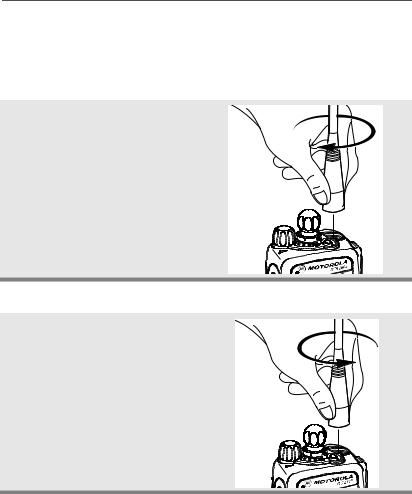
Antenna
For information regarding other available antennas, see page 43.
Attach the Antenna
With the radio off, turn the antenna clockwise to attach it.
Remove the Antenna
With the radio off, turn the antenna counter-clockwise to remove it.
10
General Radio Operation
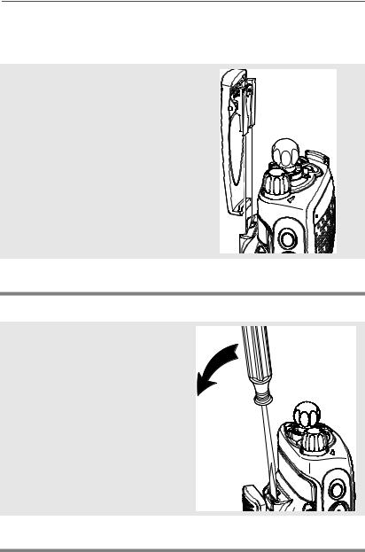
Belt Clip
Attach the Belt Clip
1Align the grooves of the belt clip with those of the battery.
2Press the belt clip downward until you clear a “click.”
Remove the Belt Clip
1Use a flat-bladed object to press the belt clip tab away from the battery.
2Slide the belt clip upward to remove it.
ASTRO XTS 2500 Model I |
11 |
General Radio Operation
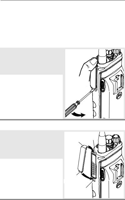
Universal Connector Cover
The universal connector cover is located on the antenna side of the radio. It is used to connect certain accessories to the radio.
Note: To prevent damage to the connector, shield it with the connector cover when not in use.
Remove the Connector Cover
1 Insert a flat-bladed screwdriver into the area between the bottom of the cover and the slot below the connector.
2Hold the top of the cover with your thumb while you pry the
bottom of the cover away from the radio with the screwdriver.
Attach the Connector Cover
1Insert the hooked end of the cover into the top of the connector. Press downward on the cover’s top to seat it into the slot.
2Press the cover’s lower tab below the connector until it snaps in place.
Top Top
Hooked End Slot
Tab
Bottom
Hooked End
Bottom
Slot
12
 Loading...