

Motorola SN54LS283J, SN74LS283D, SN74LS283N Datasheet
5-1
FAST AND LS TTL DATA
4-BIT BINARY FULL ADDER
WITH FAST CARRY
The SN54/74LS283 is a high-speed 4-Bit Binary Full Adder with internal
carry lookahead. It accepts two 4-bit binary words (A1–A4, B1–B4) and a
Carry Input (C0). It generates the binary Sum outputs (∑1–∑4) and the Carry
Output (C4) from the most significant bit. The LS283 operates with either active HIGH or active LOW operands (positive or negative logic).
14 13 12 11 10 9
1 2 3 4 5 6
7
16 15
8
V
CC
Σ
2
B3A
3
Σ
3A4
Σ
4
B
4
C
4
B2A2Σ
1A1B1
C0GND
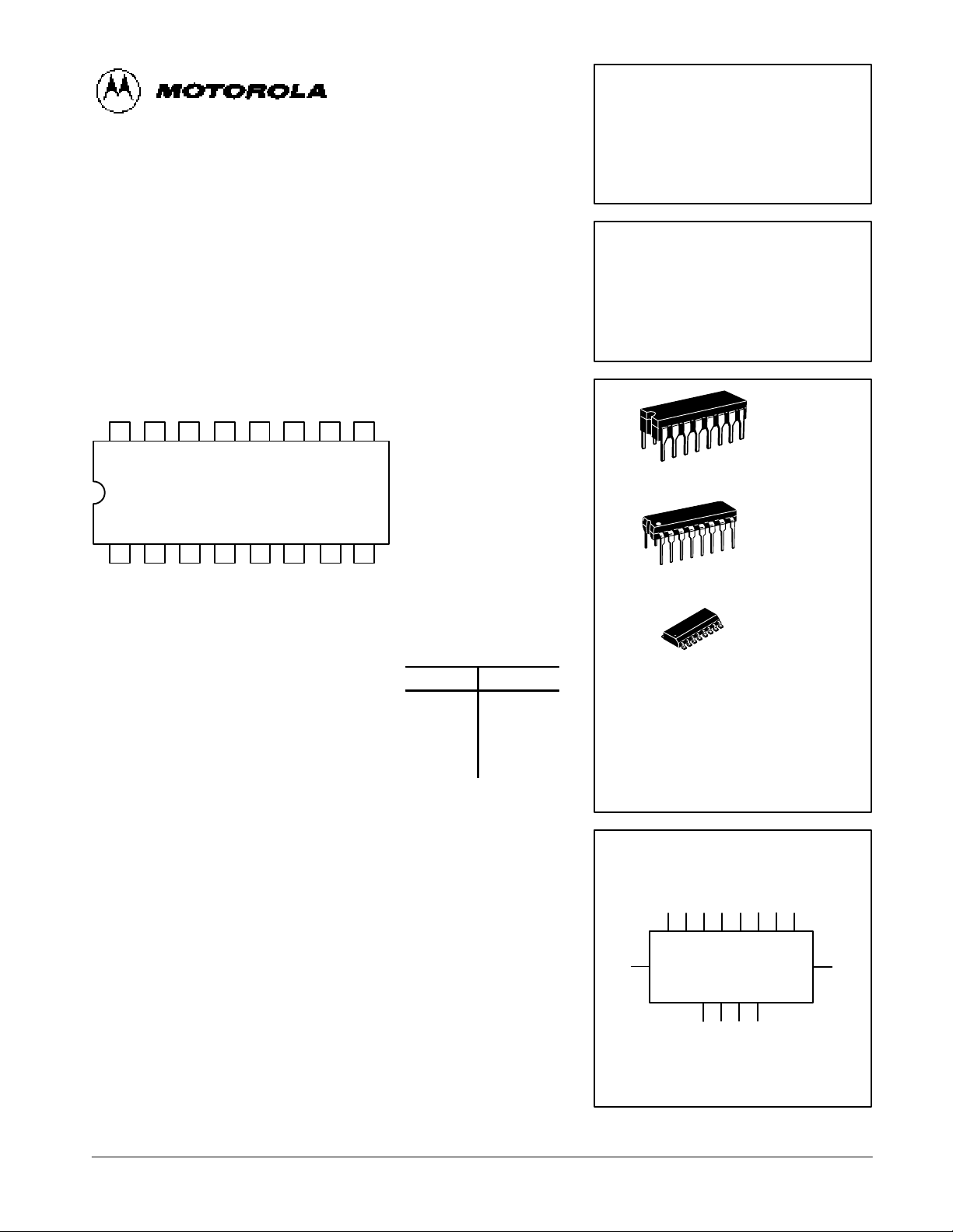
CONNECTION DIAGRAM DIP (TOP VIEW)
NOTE:
The Flatpak version
has the same pinouts
(Connection Diagram) as
the Dual In-Line Package.
PIN NAMES
LOADING (Note a)
HIGH
LOW
A1–A
4
Operand A Inputs 1.0 U.L. 0.5 U.L.
B1–B
4
Operand B Inputs 1.0 U.L. 0.5 U.L.
C
0
Carry Input 0.5 U.L. 0.25 U.L.
∑1–∑
4
Sum Outputs (Note b) 10 U.L. 5 (2.5) U.L.
C
4
Carry Output (Note b) 10 U.L. 5 (2.5) U.L.
NOTES:
a) 1 TTL Unit Load (U.L.) = 40 µA HIGH/1.6 mA LOW.
b) The Output LOW drive factor is 2.5 U.L. for Military (54) and 5 U.L. for Commercial
(74) Temperature Ranges.
SN54/74LS283
4-BIT BINARY FULL ADDER
WITH FAST CARRY
LOW POWER SCHOTTKY
ORDERING INFORMATION
SN54LSXXXJ Ceramic
SN74LSXXXN Plastic
SN74LSXXXD SOIC
J SUFFIX
CERAMIC
CASE 620-09
N SUFFIX
PLASTIC
CASE 648-08
16
1
16
1
16
1
D SUFFIX
SOIC
CASE 751B-03
LOGIC SYMBOL
5 3 14 12 6 2 15 11
97
4 1 13 10
A1A2A3A4B1B2B3B
4
∑1∑2∑3∑
4
VCC = PIN 16
GND = PIN 8
C
0
C
4
5-2
FAST AND LS TTL DATA
SN54/74LS283
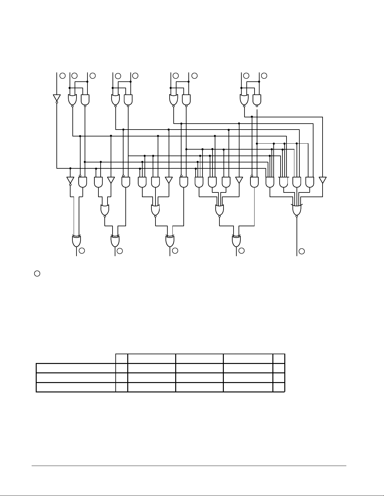
LOGIC DIAGRAM
C0A
1
B
1
A
2
B
2
A
3
B
3
A
4
B
4
∑
1
∑
2
∑
3
∑
4
C
4
VCC = PIN 16
GND = PIN 8
= PIN NUMBERS
C
1
C
2
C
3
14
1
267
3
4
5
9
11
12
10
13
15
FUNCTIONAL DESCRIPTION
The LS283 adds two 4-bit binary words (A plus B) plus the
incoming carry. The binary sum appears on the sum outputs
(∑1–∑4) and outgoing carry (C4) outputs.
C0 + (A1 + B1) + 2(A2 + B2) + 4(A3 + B3) + 8(A4 + B4) = ∑1 + 2 ∑
2
+ 4 ∑3 + 8 ∑4 + 16C
4
Where: (+) = plus
Due to the symmetry of the binary add function the LS283
can be used with either all inputs and outputs active HIGH
(positive logic) or with all inputs and outputs active LOW
(negative logic). Note that with active HIGH inputs, Carry Input
can not be left open, but must be held LOW when no carry in is
intended.
Example:
C0A1A2A3A4B1B2B3B4∑1∑2∑3∑4C
4
logic levels L L H L H H L L H H H L L H
Active HIGH 0 0 1 0 1 1 0 0 1 1 1 0 0 1 (10+9=19)
Active LOW 1 1 0 1 0 0 1 1 0 0 0 1 1 0 (carry+5+6=12)
Interchanging inputs of equal weight does not affect the operation, thus C0, A1, B1, can be arbitrarily assigned to pins 7, 5 or 3.
 Loading...