


SPLIT-TYPE, HEAT PUMP AIR CONDITIONERS
|
September 2008 |
SERVICE MANUAL |
No.OCH425 |
REVISED EDTION-A |
|
|
|
R410A
Outdoor unit
[model names]
PUHZ-HRP71VHA
PUHZ-HRP100VHA
PUHZ-HRP100YHA
PUHZ-HRP125YHA
PUHZ-HRP71VHA2
PUHZ-HRP100VHA2
PUHZ-HRP100YHA2
PUHZ-HRP125YHA2
[Service Ref.]
PUHZ-HRP71VHA PUHZ-HRP100VHA PUHZ-HRP100YHA PUHZ-HRP125YHA PUHZ-HRP71VHA2
PUHZ-HRP100VHA2 PUHZ-HRP100YHA2 PUHZ-HRP125YHA2
Revison:
•PUHZ-HRP71/100VHA2 and PUHZ-HRP100/125YHA2 are added in REVISED EDITION-A.
•Some descriptions have been modified.
•Please void OCH425.
NOTE:
•This manual describes only service data of the outdoor units.
•RoHS compliant products have <G> mark on the spec name plate.
CONTENTS
1.TECHNICAL CHANGES································· 2
2.REFERENCE MANUAL·································· 2
3. SAFETY PRECAUTION ································· 3
4.FEATURES ····················································· 7
5.SPECIFICATIONS··········································· 8
6.DATA······························································· 9
7.OUTLINES AND DIMENSIONS···················· 12
8.WIRING DIAGRAM······································· 14
9.WIRING SPECIFICATIONS ·························· 18
10. REFRIGERANT SYSTEM DIAGRAM ········ 23
11.TROUBLESHOOTING ································ 25
12.FUNCTION SETTING ································· 83
13.MONITORING THE OPERATION DATA BY THE REMOTE CONTROLLER ···· 90
14.EASY MAINTENANCE FUNCTION ········· 100
15. DISASSEMBLY PROCEDURE················· 105
PARTS CATALOG (OCB425)
PUHZ-HRP71VHA
PUHZ-HRP100VHA
PUHZ-HRP100YHA
PUHZ-HRP125YHA

1 
 TECHNICAL CHANGES
PUHZ-HRP 71VHA |
|
PUHZ-HRP 71VHA2 |
|
PUHZ-HRP100VHA PUHZ-HRP100VHA2
•Add pressure sensor (63HS).
•Compressor (MC) has been changed.
ANB33FJCMT  ANB33FJEMT
•Thermistor (Discharge / TH4) has been changed.
•Fan motors (MF1,2) have been changed.
•Fan grilles have been changed.
•Electrical parts have been changed.
Controller circuit board (C.B.), Power circuit board (P.B.),
Noise filter circuit board (N.F.) and active filter module (ACTM) (including P.B.)
PUHZ-HRP100YHA  PUHZ-HRP100YHA2
PUHZ-HRP125YHA PUHZ-HRP125YHA2
•Add pressure sensor (63HS).
•Compressor (MC) has been changed.
ANB33FJBMT  ANB33FJDMT
•Thermistor (Discharge / TH4) has been changed.
•Fan motors (MF1,2) have been changed.
•Fan grilles have been changed.
•Controller circuit board (C.B.) have been changed.
2 |
|
REFERENCE MANUAL |
|
|
|||
2-1. INDOOR UNIT SERVICE MANUAL |
|
|
|
||||
|
|
|
|
|
|
|
|
|
Model name |
|
Service Ref. |
Service |
|
||
|
|
|
|
|
|
Manual No. |
|
|
|
|
|
|
|
|
|
|
PLA-RP35/50/60/100/125BA |
|
PLA-RP35/50/60/100/125BA(1).UK/BA#2.UK |
OCH412 |
|
||
|
PLA-RP100/125BA2 |
|
PLA-RP100/125BA2.UK |
OCB412 |
|
||
|
PKA-RP60/100FAL |
|
PKA-RP60/100FAL |
OC331 |
|
||
|
PKA-RP50FAL2 |
|
PKA-RP50FAL2 |
|
|||
|
|
|
|
||||
|
PEAD-RP50/60/71/125EA |
|
PEAD-RP50/60/71/125EA.UK |
HWE05210 |
|
||
|
PEAD-RP100EA2 |
|
PEAD-RP100EA2.UK |
|
|||
|
|
|
|
||||
|
PEAD-RP60/71/100GA |
|
PEAD-RP60/71/100GA.UK |
HWE05060 |
|
||
|
|
|
|
|
|
|
|
|
|
|
|
|
|
|
|
2-2. TECHNICAL DATABOOK |
|
|
|
||||
Manual No. OCS11 |
|
|
|
||||
2
3 
 SAFETY PRECAUTION
3-1. ALWAYS OBSERVE FOR SAFETY
Before obtaining access to terminal, all supply circuits must be disconnected.
3-2. CAUTIONS RELATED TO NEW REFRIGERANT
Cautions for units utilizing refrigerant R410A
Use new refrigerant pipes.
In case of using the existing pipes for R22, be careful with the followings.
·Be sure to perform replacement operation before test run.
·Change flare nut to the one provided with this product. Use a newly flared pipe.
·Avoid using thin pipes.
Make sure that the inside and outside of refrigerant piping is clean and it has no contamination such as sulfur hazardous for use, oxides, dirt, shaving particles, etc.
In addition, use pipes with specified thickness.
Contamination inside refrigerant piping can cause deterioration of refrigerant oil etc.
Store the piping to be used during installation indoors and keep both ends of the piping sealed until just before brazing. (Leave elbow joints, etc. in their packaging.)
If dirt, dust or moisture enters into refrigerant cycle, that can cause deterioration of refrigerant oil or malfunction of compressor.
Use ester oil, ether oil or alkylbenzene oil (small amount) as the refrigerant oil applied to flares and flange connections.
If large amount of mineral oil enters, that can cause deterioration of refrigerant oil etc.
Charge refrigerant from liquid phase of gas cylinder.
If the refrigerant is charged from gas phase, composition change may occur in refrigerant and the efficiency will be lowered.
Do not use refrigerant other than R410A.
If other refrigerant (R22 etc.) is used, chlorine in refrigerant can cause deterioration of refrigerant oil etc.
Use a vacuum pump with a reverse flow check valve.
Vacuum pump oil may flow back into refrigerant cycle and that can cause deterioration of refrigerant oil etc.
Use the following tools specifically designed for use with R410A refrigerant.
The following tools are necessary to use R410A refrigerant.
|
Tools for R410A |
|
Gauge manifold |
|
Flare tool |
Charge hose |
|
Size adjustment gauge |
Gas leak detector |
|
Vacuum pump adaptor |
Torque wrench |
|
Electronic refrigerant |
|
|
charging scale |
Keep the tools with care.
If dirt, dust or moisture enters into refrigerant cycle, that can cause deterioration of refrigerant oil or malfunction of compressor.
Do not use a charging cylinder.
If a charging cylinder is used, the composition of refrigerant will change and the efficiency will be lowered.
Ventilate the room if refrigerant leaks during operation. If refrigerant comes into contact with a flame, poisonous gases will be released.
[1]Cautions for service
(1)Perform service after recovering the refrigerant left in unit completely.
(2)Do not release refrigerant in the air.
(3)After completing service, charge the cycle with specified amount of refrigerant.
(4)When performing service, install a filter drier simultaneously. Be sure to use a filter drier for new refrigerant.
[2]Additional refrigerant charge
When charging directly from cylinder
·Check that cylinder for R410A on the market is syphon type.
·Charging should be performed with the cylinder of syphon stood vertically. (Refrigerant is charged from liquid phase.)
3
Unit
Gravimeter
[3] Service tools
Use the below service tools as exclusive tools for R410A refrigerant.
No. |
Tool name |
|
Specifications |
||
1 |
Gauge manifold |
·Only for R410A |
|
|
|
|
|
·Use the existing fitting specifications. (UNF1/2) |
|||
|
|
·Use high-tension side pressure of 5.3MPa·G or over. |
|||
2 |
Charge hose |
·Only for R410A |
|
|
|
|
|
·Use pressure performance of 5.09MPa·G or over. |
|||
3 |
Electronic scale |
|
|
|
|
|
|
|
|
||
4 |
Gas leak detector |
·Use the detector for R134a, R407C or R410A. |
|||
5 |
Adaptor for reverse flow check |
·Attach on vacuum pump. |
|||
6 |
Refrigerant charge base |
|
|
|
|
|
|
|
|
||
7 |
Refrigerant cylinder |
·Only for R410A |
·Top of cylinder (Pink) |
||
|
|
·Cylinder with syphon |
|
|
|
8 |
Refrigerant recovery equipment |
|
|
|
|
|
|
|
|
||
[4] Refrigerant leakage detection function
This air conditioner can detect refrigerant leakage which may happen during a long period of use. In order to enable the leakage detection, settings are required to let the unit memorize the initial conditions(initial learning). Refer to 14-3. INITIAL SETTINGS FOR REFRIGERANT LEAKAGE DETECTION FUNCTION.
4
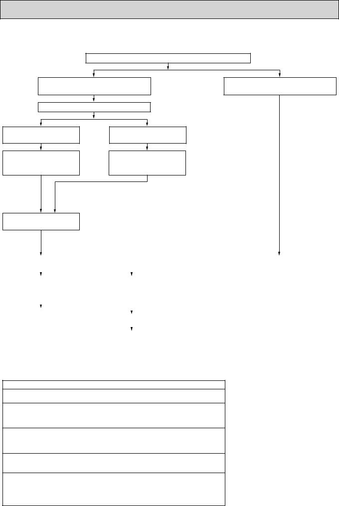
3-3. PRECAUTIONS WHEN REUSING EXISTING R22 REFRIGERANT PIPES
(1) Flowchart
Measure the existing pipe thickness and check for damage.
The existing pipe thickness meets specifications and the pipes are not damaged.
Check if existing air conditioner can operate.
The existing pipe thickness does not meet specifications or the pipes are damaged.
Existing air conditioner can operate.
Perform cooling operation for about 30 minutes and then do a pump down work.
Existing air conditioner cannot operate.
Use a refrigerant recovery equipment to recover the refrigerant.
+ In case existing pipes were used for gas or oil heat pump system,
be sure to clean the pipes for HRP71,100,125 models.
Disconnect existing air conditioner from piping.
Existing pipes can be reused. |
|
|
|
|
Existing pipes cannot be |
|
|
|
|
|
|
|
|
reused. Use new pipes. |
|
|
|
|
|
|
|||
|
|
|
|
|
|||
|
|
|
|
|
|
|
|
|
|
|
|
|
|
|
|
In case the unit is RP35/50 |
|
In case the unit is HRP71, |
|
|
|
||
or RP60/71VHA2(1) which |
|
|
|
|
|||
|
100, 125 which utilize |
|
|
|
|||
utilizes HAB oil. |
|
|
|
|
|||
|
ester oil or ether oil. |
|
|
|
|||
|
|
|
|
|
|
||
|
|
|
|
|
|
|
|
|
|
|
|
|
|
|
|
Connect a new air conditioner. |
|
|
|
|
|
|
|
|
|
|
|
|
|
||
|
Connect a new air conditioner. |
|
|
|
|||
|
|
|
|
|
|
||
|
|
|
|
|
|
|
|
|
|
|
|
|
|
||
|
|
|
Perform replacement operation. |
|
|||
|
|
|
|
|
|
|
|
|
|
|
·When performing replacement operation, make sure that DIP SW8-2 on outdoor unit controller board is |
||||
|
|
|
set to ON. |
||||
|
|
|
+Chemical compounds containing chlorine left in existing pipes are collected by replace filter. |
||||
|
|
|
●The air conditioner automatically performs cooling operation through replace filter for about 2 hours. |
||||
Connecting a new air conditioner
Flaring work should be done so that flare meets the dimension for R410A. Use flare nut provided with indoor and outdoor unit.
When using gas piping of :19.05mm for HRP100, 125.
Make sure that DIP SW8-1 on outdoor unit controller board is set to ON.This is to keep the pressure on pipes within permissible range.
●Use different diameter joint or adjust the piping size by brazing.
When using pipes larger than specified size for HRP71.
Make sure that DIP SW8-1 on outdoor unit controller board is set to ON.
This is to prevent oil flow ratio from lowering due to the decrease in flowing refrigerant. ●Use different diameter joint or adjust the piping size by brazing.
When existing pipes are specified size.
The pipes can be reused referring to TECHNICAL DATA BOOK (OCS11). ●Use different diameter joint or adjust the piping size by brazing.
* When using existing pipes for HRP71, 100, 125
Make sure that DIP SW8-2 on outdoor unit controller board is set to ON and perform replacement operation.
+Chemical compounds containing chlorine left in existing pipes are collected by replace filter.
●The air conditioner automatically performs cooling operation through replace filter for about 2 hours.
5
(2)Cautions for refrigerant piping work
New refrigerant R410A is adopted for replacement inverter series. Although the refrigerant piping work for R410A is same as for R22, exclusive tools are necessary so as not to mix with different kind of refrigerant. Furthermore as the working pressure of R410A is 1.6 time higher than that of R22, their sizes of flared sections and flare nuts are different.
1Thickness of pipes
Because the working pressure of R410A is higher compared to R22, be sure to use refrigerant piping with thickness shown below. (Never use pipes of 0.7mm or below.)
Diagram below: Piping diameter and thickness |
|
||
Nominal |
Outside |
Thickness (mm) |
|
dimensions(inch) |
diameter (mm) |
R410A |
R22 |
1/4 |
6.35 |
0.8 |
0.8 |
3/8 |
9.52 |
0.8 |
0.8 |
1/2 |
12.70 |
0.8 |
0.8 |
5/8 |
15.88 |
1.0 |
1.0 |
3/4 |
19.05 |
— |
1.0 |
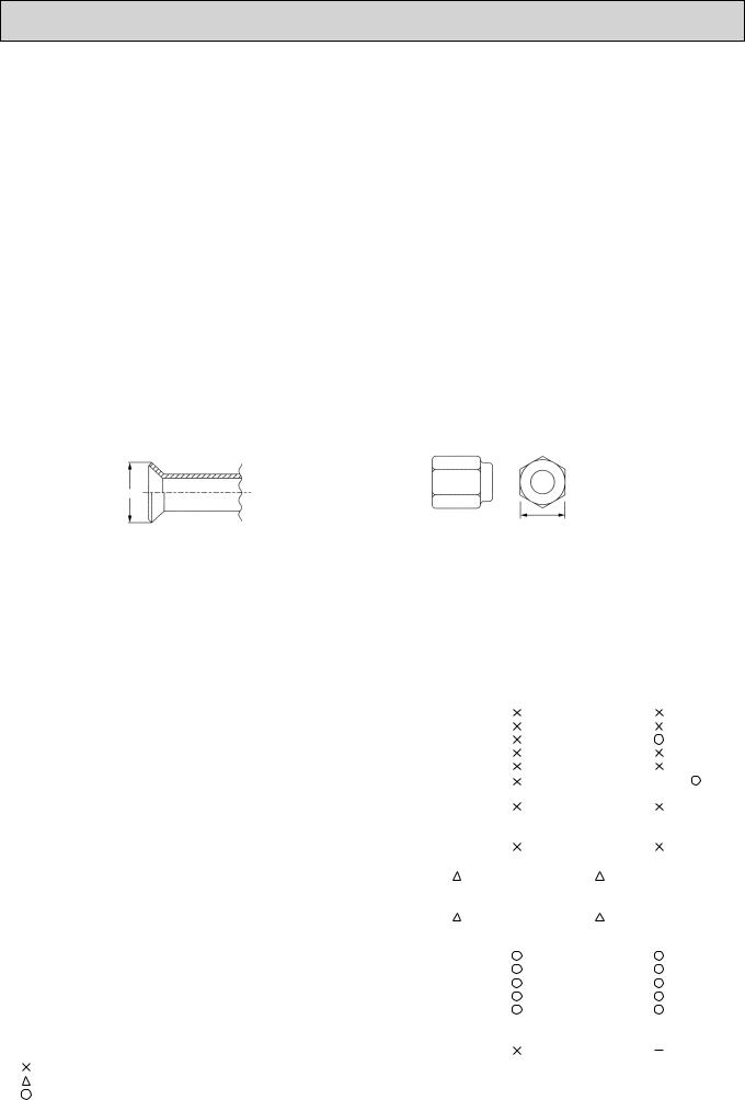
2Dimensions of flare cutting and flare nut
The component molecules in HFC refrigerant are smaller compared to conventional refrigerants. In addition to that, R410A is a refrigerant, which has higher risk of leakage because its working pressure is higher than that of other refrigerants. Therefore, to enhance airtightness and intensity, flare cutting dimension of copper pipe for R410A have been specified separately from the dimensions for other refrigerants as shown below. The dimension B of flare nut for R410A also has partly been changed to increase intensity as shown below. Set copper pipe correctly referring to copper pipe flaring dimensions for R410A below. For 1/2 and 5/8 inch, the dimension B changes.
Use torque wrench corresponding to each dimension.
Dimension A |
|
|
|
|
|
|
|
|
|
|
|
|
|
|
|
|
|
|
|
Dimension B |
|
|
|
Flare cutting dimensions |
|
(mm) |
Flare nut dimensions |
|
|
(mm) |
|
||||
Nominal |
Outside |
Dimension A ( -+00.4 ) |
|
Nominal |
|
Outside |
Dimension B |
|
|
||
dimensions(inch) |
diameter |
R410A |
R22 |
|
dimensions(inch) |
|
diameter |
R410A |
R22 |
|
|
1/4 |
6.35 |
9.1 |
9.0 |
|
1/4 |
|
6.35 |
17.0 |
17.0 |
|
|
3/8 |
9.52 |
13.2 |
13.0 |
|
3/8 |
|
9.52 |
22.0 |
22.0 |
|
+36.0mm for |
1/2 |
12.70 |
16.6 |
16.2 |
|
1/2 |
|
12.70 |
26.0 |
24.0 |
|
indoor unit |
5/8 |
15.88 |
19.7 |
19.4 |
|
5/8 |
|
15.88 |
29.0 + |
27.0 |
|
of RP100, |
3/4 |
19.05 |
— |
23.3 |
|
3/4 |
|
19.05 |
- |
36.0 |
|
125 and 140 |
3Tools for R410A (The following table shows whether conventional tools can be used or not.)
Tools and materials |
Use |
R410A tools |
Can R22 tools be used? |
Can R407C tools be used? |
Gauge manifold |
Air purge, refrigerant charge |
Tool exclusive for R410A |
|
|
Charge hose |
and operation check |
Tool exclusive for R410A |
|
|
Gas leak detector |
Gas leak check |
Tool for HFC refrigerant |
|
|
Refrigerant recovery equipment |
Refrigerant recovery |
Tool exclusive for R410A |
|
|
Refrigerant cylinder |
Refrigerant charge |
Tool exclusive for R410A |
|
|
Applied oil |
Apply to flared section |
Ester oil, ether oil and alky- |
|
Ester oil, ether oil: |
|
|
lbenzene oil (minimum amount) |
|
Alkylbenzene oil: minimum amount |
Safety charger |
Prevent compressor malfunction |
Tool exclusive for R410A |
|
|
|
when charging refrigerant by |
|
|
|
|
spraying liquid refrigerant |
|
|
|
Charge valve |
Prevent gas from blowing out |
Tool exclusive for R410A |
|
|
|
when detaching charge hose |
|
|
|
Vacuum pump |
Vacuum drying and air |
Tools for other refrigerants can |
(Usable if equipped |
(Usable if equipped |
|
purge |
be used if equipped with adop- |
with adopter for rever- |
with adopter for rever- |
|
|
ter for reverse flow check |
se flow) |
se flow) |
Flare tool |
Flaring work of piping |
Tools for other refrigerants |
(Usable by adjusting |
(Usable by adjusting |
|
|
can be used by adjusting |
flaring dimension) |
flaring dimension) |
|
|
flaring dimension |
|
|
Bender |
Bend the pipes |
Tools for other refrigerants can be used |
|
|
Pipe cutter |
Cut the pipes |
Tools for other refrigerants can be used |
|
|
Welder and nitrogen gas cylinder |
Weld the pipes |
Tools for other refrigerants can be used |
|
|
Refrigerant charging scale |
Charge refrigerant |
Tools for other refrigerants can be used |
|
|
Vacuum gauge or thermis- |
Check the degree of vacuum. (Vacuum |
Tools for other refrigerants |
|
|
tor vacuum gauge and |
valve prevents back flow of oil and refri- |
can be used |
|
|
vacuum valve |
gerant to thermistor vacuum gauge) |
|
|
|
Charging cylinder |
Refrigerant charge |
Tool exclusive for R410A |
|
|
:Prepare a new tool. (Use the new tool as the tool exclusive for R410A.)
:Tools for other refrigerants can be used under certain conditions.
:Tools for other refrigerants can be used.
6
4 
 FEATURES
PUHZ-HRP71/100VHA |
PUHZ-HRP71/100VHA2 |
PUHZ-HRP100/125YHA |
PUHZ-HRP100/125YHA2 |
HIGH HEATING CAPACITY
Industry-first flash injection circuit is equipped, which enables to keep the equal capacity with the rating even when outside temperature is -15:.
HIGH SPEED HEATING START UP
The performance of heating start up is improved. Compared to RP type, Zubadan reduced the time for heating start up by about half. After starting operation, the airflow temperature goes up to 45: quickly in 10 minutes. With industry-first shorter and less frequent defrost, defrosting time is cut down by 15% compared to RP type and heating operation can continuously run for maximum 150 minutes.
WIDE HEATING RANGE
The heating range is expanded to -25: compared to RP type which is up to -20:.
|
(kW) |
Performance |
|
|
|
|
|
|
15 |
about 30%UP |
|
|
HRP125 |
|
|
|
|
|
|
|
|
|
|
capacity |
|
|
|
|
|
RP125 |
HRP100 |
|
|
|
|
|
|
||
10 |
|
|
|
|
RP100 |
|
|
Heating |
|
|
|
|
|
|
HRP71 |
|
|
|
|
|
|
|
|
|
|
|
|
|
|
RP71 |
|
|
0 |
-25 |
-20 |
-15 |
-10 |
-5 |
0 |
Outdoor W.B. temp.
When stabled,
hot air of 50
Heating capacity(Peak)
(kW)
15
10
0
HRP100
Outlet air temp.45
13kW
(Outlet air temp. 45 ) . 10min About
It doesn’t reach 50 when outside air temp. is too low,
+1
|
Stable |
|
. |
About |
19 min |
RP type:
Outlet air temp. 45
About 50% CUT
|
|
|
5 |
10 |
15 |
20 |
0 |
||||||
|
|
|
|
Elapsed time(min.) |
|
|
+1 Condition |
|
|
|
|
||
Room temp. 20 |
(D.B.) |
Outdoor temp. 2 |
(D.B.)/1 |
(W.B.) : Unit HRP100, Hi notch |
||
|
|
|
|
|
|
(Indoor PKA type) |
Expanded |
|
|
|
|
|
|
|
Up to -25 |
-11~ |
|
RP type |
||||
|
-20 |
|
|
|
|
|
|
|
-25 |
|
|
HRP type |
|||
|
|
|
|
|
|
|
|
|
|
|
|
|
|
|
|
-25 -20 -15 -10 -5 0 Outdoor wet-bulb temperature
CHARGELESS SYSTEM
PRE-CHARGED REFRIGERANT IS SUPPLIED FOR PIPING LENGTH AT SHIPMENT. Max.30m(PUHZ-HRP71/100/125)
The refrigerant circuit with LEV(Linear Expansion Valve) and power receiver always control the optimal refrigerant level regardless of the length (30m max. and 5m min.) of piping. The additional refrigerant charging work during installation often causes problems. It is completely eliminated by chargelss system. This unique system improves the quality and reliability of the work done. It also helps to speed up the installation time.
REFRIGERANT LEAKAGE DETECTION FUNCTION
PUHZ-HRP·HA(2) can detect refrigerant leakage which may happen during a long period of use.
7
, PUHZ-HRP100VHA(2), PUHZ-HRP100YHA(2), PUHZ-HRP125YHA(2) Service Manual")
5 
 SPECIFICATIONS
Service Ref. |
|
|
|
|
Mode |
|
|
|
|
|
Power supply (phase, cycle, voltage) |
|
||
|
|
Max. current |
|
A |
|
External finish |
|
|
|
|
Refrigerant control |
|
|
|
|
Compressor |
|
|
|
|
|
Model |
|
|
|
|
Motor output |
|
kW |
|
|
Starter type |
|
|
|
|
Protection devices |
|
|
UNIT |
Crankcase heater |
|
W |
|
OUTDOOR |
Heat exchanger |
|
|
|
Defrost method |
|
|
||
|
Fan |
Fan(drive) % No. |
|
|
|
|
Fan motor output |
|
kW |
|
|
Airflow |
*/min(CFM) |
|
|
Noise level |
Cooling |
dB |
|
|
Dimensions |
Heating |
dB |
|
|
W |
mm(in.) |
||
|
|
|
D |
mm(in.) |
|
Weight |
|
H |
mm(in.) |
|
|
|
kg(lbs) |
|
|
Refrigerant |
|
|
|
|
|
Charge |
|
kg(lbs) |
PIPING |
|
Oil (Model) |
Liquid |
L |
Pipe size O.D. |
mm(in.) |
|||
outdoor unit |
Gas |
mm(in.) |
||
REFRIGERANT |
Piping length |
|
||
|
Connection method |
Indoor side |
|
|
|
|
|
Outdoor side |
|
|
Between the indoor & |
Height difference |
||
Service Ref. |
|
|
|
|
Mode |
|
|
|
|
|
Power supply (phase, cycle, voltage) |
|
||
|
|
Max. current |
|
A |
|
External finish |
|
|
|
|
Refrigerant control |
|
|
|
|
Compressor |
|
|
|
|
|
Model |
|
|
|
|
Motor output |
|
kW |
|
|
Starter type |
|
|
|
|
Protection devices |
|
|
UNIT |
Crankcase heater |
|
W |
|
|
|
|||
OUTDOOR |
Heat exchanger |
|
|
|
Defrost method |
|
|
||
|
Fan |
Fan(drive) % No. |
|
|
|
|
Fan motor output |
|
kW |
|
|
Airflow |
*/min(CFM) |
|
|
Noise level |
Cooling |
dB |
|
|
Dimensions |
Heating |
dB |
|
|
W |
mm(in.) |
||
|
|
|
D |
mm(in.) |
|
Weight |
|
H |
mm(in.) |
|
|
|
kg(lbs) |
|
|
Refrigerant |
|
|
|
|
|
Charge |
|
kg(lbs) |
PIPING |
|
Oil (Model) |
Liquid |
L |
Pipe size O.D. |
mm(in.) |
|||
|
|
Gas |
mm(in.) |
|
REFRIGERANT |
Connection method |
Indoor side |
|
|
outdoor unit |
Piping length |
|
||
|
|
|
Outdoor side |
|
|
Between the indoor & |
Height difference |
||
PUHZ-HRP71/100VHA |
|
PUHZ-HRP71/100VHA2 |
||
Cooling |
Heating |
|
Cooling |
Heating |
|
Single 50Hz, 230V |
|
||
|
|
28 |
|
|
|
Munsell 3Y 7.8/1.1 |
|
||
|
Linear Expansion Valve |
|
||
|
|
Hermetic |
|
|
ANB33FJCMT |
|
ANB33FJEMT |
||
|
|
2.5 |
|
|
|
|
Inverter |
|
|
|
|
HP switch |
|
|
|
|
LP switch |
|
|
|
Discharge thermo |
|
||
|
|
— |
|
|
|
|
Plate fin coil |
|
|
0.086+0.086 |
Propeller fan % 2 |
0.074+0.074 |
||
|
|
|
||
|
|
100(3,530) |
|
|
52 |
Reverse cycle |
51 |
||
|
|
|
||
53 |
|
950(37-3/8) |
52 |
|
|
|
|
||
|
330+30(13+1-3/16) |
|
||
|
1,350(53-1/8) |
|
||
|
|
120(265) |
|
|
|
|
R410A |
|
|
|
|
5.5(12.1) |
|
|
|
|
1.40(FV50S) |
|
|
|
|
9.52(3/8) |
|
|
|
|
15.88(5/8) |
|
|
|
|
Flared |
|
|
|
|
Flared |
|
|
|
|
Max. 30m |
|
|
|
|
Max. 75m |
|
|
PUHZ-HRP100/125YHA |
|
PUHZ-HRP100/125YHA2 |
||
Cooling |
Heating |
|
Cooling |
Heating |
|
3phase, 50Hz, 400V |
|
||
|
|
14 |
|
|
|
Munsell 3Y 7.8/1.1 |
|
||
|
Linear Expansion Valve |
|
||
|
|
Hermetic |
|
|
ANB33FJBMT |
|
ANB33FJDMT |
||
|
|
2.5 |
|
|
|
|
Inverter |
|
|
|
|
HP switch |
|
|
|
|
LP switch |
|
|
|
Discharge thermo |
|
||
|
|
— |
|
|
|
|
Plate fin coil |
|
|
0.086+0.086 |
Propeller fan % 2 |
0.074+0.074 |
||
|
|
|
||
|
|
100(3,530) |
|
|
52 |
Reverse cycle |
51 |
||
|
|
|
||
53 |
|
950(37-3/8) |
52 |
|
|
|
|
||
330+30(13+1-3/16) 1,350(53-1/8)
134(295)
R410A
5.5(12.1)
1.40(FV50S)
9.52(3/8)
15.88(5/8) Flared Flared Max. 30m Max. 75m
8

6 |
|
DATA |
|
|
|
|
|
|
|
|
|
|
|
|
6-1. REFILLING REFRIGERANT CHARGE (R410A : kg) |
|
|
|
|
|
|||||||||
|
|
|
|
|
|
|
|
|
|
|
|
|
||
Service Ref. |
|
|
|
Piping length (one way) |
|
|
|
Factory |
||||||
|
10m |
20m |
30m |
|
40m |
|
50m |
60m |
75m |
charged |
||||
|
|
|
|
|
|
|||||||||
PUHZ-HRP71VHA(2) |
|
5.1 |
5.3 |
5.5 |
6.1 |
|
6.7 |
7.3 |
7.9 |
|
5.5 |
|||
|
|
|
|
|
|
|
|
|
|
|
|
|
||
PUHZ-HRP100VHA(2) |
|
5.1 |
5.3 |
5.5 |
6.1 |
|
6.7 |
7.3 |
7.9 |
|
5.5 |
|||
PUHZ-HRP100YHA(2) |
|
|
|
|
|
|
|
|
|
|
|
|
||
PUHZ-HRP125YHA(2) |
|
5.1 |
5.3 |
5.5 |
6.1 |
|
6.7 |
7.3 |
7.9 |
|
5.5 |
|||
|
|
|
|
|
|
|
|
|
|
|
|
|
|
|
|
|
|
|
|
|
|
|
|
|
|
||||
|
|
|
|
|
|
|
|
For pipe longer than 30m, additional charge |
|
|
||||
|
|
|
|
|
|
|
|
is required. |
|
|
|
|
|
|
|
|
|
|
|
|
|
|
|
|
|
|
|
|
|
6-2. COMPRESSOR TECHNICAL DATA
|
|
|
(at 20 |
) |
Service Ref. |
PUHZ-HRP71VHA |
PUHZ-HRP100YHA |
|
|
PUHZ-HRP100VHA |
PUHZ-HRP125YHA |
|
||
|
|
|
||
Compressor model |
ANB33FJCMT |
ANB33FJBMT |
|
|
|
|
|
|
|
Winding |
U-V |
0.188 |
0.302 |
|
|
|
|
|
|
U-W |
0.188 |
0.302 |
|
|
Resistance |
|
|||
( ) |
|
|
|
|
W-V |
0.188 |
0.302 |
|
|
|
|
|||
|
|
|
(at 20 |
) |
Service Ref. |
PUHZ-HRP71VHA2 |
PUHZ-HRP100YHA2 |
|
|
PUHZ-HRP100VHA2 |
PUHZ-HRP125YHA2 |
|
||
|
|
|
||
Compressor model |
ANB33FJEMT |
ANB33FJDMT |
|
|
|
|
|
|
|
Winding |
U-V |
0.188 |
0.302 |
|
|
|
|
|
|
U-W |
0.188 |
0.302 |
|
|
Resistance |
|
|||
( ) |
|
|
|
|
W-V |
0.188 |
0.302 |
|
|
|
|
|||
9
6-3. NOISE CRITERION CURVES
PUHZ-HRP71VHA |
|
|
MODE SPL(dB) |
LINE |
PUHZ-HRP71VHA2 |
|
|
MODE SPL(dB) |
LINE |
|||||||||||
PUHZ-HRP100VHA |
|
|
COOLING |
52 |
|
PUHZ-HRP100VHA2 |
|
COOLING |
51 |
|
||||||||||
PUHZ-HRP100YHA |
|
|
HEATING |
53 |
|
PUHZ-HRP100YHA2 |
|
HEATING |
52 |
|
||||||||||
|
|
|
|
|
|
|
|
|
|
|
||||||||||
PUHZ-HRP125YHA |
|
|
|
|
|
|
PUHZ-HRP125YHA2 |
|
|
|
|
|
||||||||
μbar) |
90 |
|
|
|
|
|
|
|
|
μbar) |
90 |
|
|
|
|
|
|
|
|
|
|
|
|
|
|
|
|
|
|
|
|
|
|
|
|
|
|
|
|||
dB = 0.0002 |
80 |
|
|
|
|
|
|
|
|
dB = 0.0002 |
80 |
|
|
|
|
|
|
|
|
|
70 |
|
|
|
|
|
|
|
NC-70 |
70 |
|
|
|
|
|
|
|
NC-70 |
|||
dB (0 |
|
|
|
|
|
|
|
|
dB (0 |
|
|
|
|
|
|
|
|
|||
60 |
|
|
|
|
|
|
|
|
60 |
|
|
|
|
|
|
|
|
|||
LEVEL, |
|
|
|
|
|
|
|
NC-60 |
LEVEL, |
|
|
|
|
|
|
|
|
|||
|
|
|
|
|
|
|
|
|
|
|
|
|
|
|
|
NC-60 |
||||
|
|
|
|
|
|
|
|
|
|
|
|
|
|
|
|
|
|
|||
PRESSURE |
50 |
|
|
|
|
|
|
|
|
PRESSURE |
50 |
|
|
|
|
|
|
|
|
|
|
|
|
|
|
|
|
|
NC-50 |
|
|
|
|
|
|
|
|
NC-50 |
|||
40 |
|
|
|
|
|
|
|
|
40 |
|
|
|
|
|
|
|
|
|||
|
|
|
|
|
|
|
|
NC-40 |
|
|
|
|
|
|
|
|
NC-40 |
|||
SOUND |
|
|
|
|
|
|
|
|
SOUND |
|
|
|
|
|
|
|
|
|||
30 |
|
|
|
|
|
|
|
|
30 |
|
|
|
|
|
|
|
|
|||
|
|
|
|
|
|
|
|
NC-30 |
|
|
|
|
|
|
|
|
NC-30 |
|||
BAND |
|
|
|
|
|
|
|
|
BAND |
|
|
|
|
|
|
|
|
|||
20 |
APPROXIMATE |
|
|
|
|
|
|
20 |
APPROXIMATE |
|
|
|
|
|
|
|||||
OCTAVE |
THRESHOLD OF |
|
|
|
|
|
|
OCTAVE |
THRESHOLD OF |
|
|
|
|
|
|
|||||
|
|
|
|
|
|
NC-20 |
|
|
|
|
|
|
NC-20 |
|||||||
|
HEARING FOR |
|
|
|
|
|
|
HEARING FOR |
|
|
|
|
|
|||||||
|
CONTINUOUS |
|
|
|
|
|
|
|
CONTINUOUS |
|
|
|
|
|
|
|||||
10 |
NOISE |
|
|
|
|
|
|
|
10 |
NOISE |
|
|
|
|
|
|
|
|||
63 |
125 |
250 |
500 |
1000 |
2000 |
4000 |
8000 |
63 |
125 |
250 |
500 |
1000 |
2000 |
4000 |
8000 |
|||||
|
|
|
|
|||||||||||||||||
|
|
|
BAND CENTER FREQUENCIES, Hz |
|
|
|
|
BAND CENTER FREQUENCIES, Hz |
|
|||||||||||
|
|
|
|
|
|
|
|
|
|
|
|
|
|
|||||||
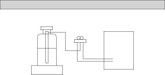
MICROPHONE
1m
UNIT
1.5m
GROUND
10
6-4. STANDARD OPERATION DATA
|
Representative matching |
|
PEAD-RP71EA |
PEAD-RP100EA2 |
PEAD-RP125EA |
||||
|
|
|
|
|
|
|
|
||
Mode |
|
Cooling |
Heating |
Cooling |
Heating |
Cooling |
Heating |
||
|
|
|
|
|
|
|
|
|
|
Total |
Capacity |
W |
7,100 |
8,000 |
10,000 |
11,200 |
12,500 |
14,000 |
|
Input |
kW |
2.15 |
2.34 |
3.06 |
3.10 |
3.89 |
3.88 |
||
|
|||||||||
|
|
|
|
|
|
|
|
|
|
|
|
Indoor unit |
|
PEAD-RP71EA |
PEAD-RP100EA2 |
PEAD-RP125EA |
||||||
|
|
|
|
|
|
|
|
|
|
|||
|
|
Phase , Hz |
|
|
1 , 50 |
1 , 50 |
|
1 , 50 |
||||
circuit |
|
|
|
|
|
|
|
|
|
|
|
|
Voltage |
V |
|
230 |
230 |
|
230 |
||||||
|
|
|
|
|||||||||
|
|
|
|
|
|
|
|
|
|
|
|
|
Electrical |
Current |
A |
1.55 |
|
1.55 |
2.62 |
2.62 |
2.62 |
|
2.62 |
||
|
|
|
|
|
|
|
|
|
||||
Outdoor unit |
|
PUHZ-HRP71VHA(2) |
PUHZ-HRP100YHA(2) |
PUHZ-HRP125YHA(2) |
||||||||
|
|
|
|
|
|
PUHZ-HRP100VHA(2) |
|
|
|
|||
|
|
|
|
|
|
|
|
|
|
|||
|
|
Phase , Hz |
|
|
1 , 50 |
1/3 , 50 |
|
3 , 50 |
||||
|
|
|
|
|
|
|
|
|
|
|||
|
|
Voltage |
V |
|
230 |
230/400 |
|
400 |
||||
|
|
|
|
|
|
|
|
|
|
|
|
|
|
|
Current |
A |
8.09 |
|
8.94 |
11.10/3.69 |
11.28/3.74 |
4.92 |
|
4.91 |
|
|
|
|
|
|
|
|
|
|
|
|
|
|
|
|
Discharge pressure |
MPa |
2.46 |
|
2.71 |
2.61 |
2.22 |
2.79 |
|
2.70 |
|
circuit |
|
|
|
|
|
|
|
|
|
|
|
|
Suction pressure |
MPa |
0.92 |
|
0.76 |
0.97 |
0.72 |
0.89 |
|
0.70 |
|||
|
|
|
|
|||||||||
|
|
|
|
|
|
|
|
|
|
|
|
|
Refrigerant |
Discharge temperature |
|
68 |
|
74 |
68 |
65 |
72 |
|
76 |
||
|
|
|
|
|
|
|
|
|
|
|
||
Condensing temperature |
|
42 |
|
43 |
44 |
37 |
47 |
|
44 |
|||
|
|
|
|
|
||||||||
|
|
|
|
|
|
|
|
|
|
|
|
|
|
|
Sunction temperature |
|
14 |
|
5 |
13 |
4 |
8 |
|
1 |
|
|
|
Ref. pipe length |
m |
7.5 |
|
7.5 |
7.5 |
7.5 |
7.5 |
|
7.5 |
|
|
|
|
|
|
|
|
|
|
|
|
|
|
side |
Intake air temperature |
D.B. |
|
27 |
|
20 |
27 |
20 |
27 |
|
20 |
|
|
|
|
|
|
|
|
|
|
|
|||
W.B. |
|
|
|
|
|
|
|
|
|
|||
Indoor |
|
|
19 |
|
15 |
19 |
15 |
19 |
|
15 |
||
|
|
|
|
|
|
|
|
|
|
|
||
Discharge air temperature |
D.B. |
|
15 |
|
38 |
16 |
35 |
15 |
|
39 |
||
|
|
|
|
|
|
|
|
|
|
|
|
|
Outdoor side |
|
W.B. |
|
24 |
|
6 |
24 |
6 |
24 |
|
6 |
|
|
|
Intake air temperature |
D.B. |
|
35 |
|
7 |
35 |
7 |
35 |
|
7 |
|
|
|
|
|
|
|
|
|
|
|
|
|
|
|
|
|
|
|
|
|
|
|
|
|
|
|
|
SHF |
|
0.85 |
|
— |
0.89 |
— |
0.85 |
|
— |
|
|
|
BF |
|
0.13 |
|
— |
0.18 |
— |
0.09 |
|
— |
|
The unit of pressure has been changed to MPa based on international SI system. The conversion factor is : 1(MPa)=10.2(kgf/cm2)
11
10m
12
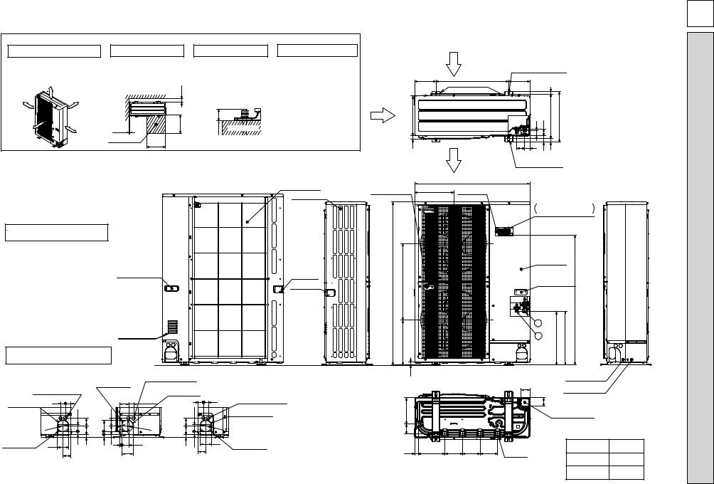
1 FREE SPACE (Around the unit)
The diagram below shows a basic example.
Explantion of particular details is given in the installation manuals etc.
|
|
FREE |
|
150mm |
Over |
|
Over |
||
|
|
|
|
|
|
|
Over |
||
|
|
1000mm |
|
1 |
|
|
|
|
0mm |
Ove |
r |
|
|
|
|
|
|
|
|
2 SERVICE SPACE
Dimensions of space needed for service access are shown in the below diagram.
|
Over 150 |
Over |
Over 500 |
10 |
|
Service space |
Over |
|
500 |
3 FOUNDATION BOLTS
Please secure the unit firmly with 4 foundation (M10) bolts. (Bolts and washers must be purchased locally.)
<Foundation bolt height>
than |
30 |
|
Less |
FOUNDATION |
4 PIPING-WIRING DIRECTIONS
Piping and wiring connections can be made from 4 directions: front, right, rear and below.
Rear Air Intake
Side Air Intake
Example of Notes
···Refrigerant GAS pipe connction (FLARE)W15.88(5/8 inch)···Refrigerant LIQUID pipe connection (FLARE)W 9.52(3/8 inch)
+1 ···Indication of STOP VALVE connection location.
Handle for moving
Air intake
Piping Knockout Hole Details
Handle for moving
Handle for moving
Power supply wiring hole (2-W27Knockout)
Front trunking hole |
40 |
45 |
|
(Knockout) |
|||
|
|
|
55 |
|
W92 |
63 |
|
73 |
||
|
Front piping hole |
92 |
27 |
23 |
|
(Knockout) |
||||
|
|
65
Right piping hole (Knockout)
75
|
63 |
|
27 92 |
|
19 |
23 |
73 |
92
|
Power supply wiring hole |
|
|
|
|
(2-W27Knockout) |
|
|
|
|
Right trunking hole |
|
||
|
(Knockout) |
|
|
|
|
40 |
|
45 |
40 |
|
|
55 |
|
|
W92 |
63 |
|
|
W |
73 |
|
|
92 |
|
|
|
|
|
|
55 |
23 |
27 |
65 |
92 |
|
|
|||
|
|
|
|
|
Power supply wiring hole (2-W27Knockout)
Rear trunking hole (Knockout)
Rear piping hole (Knockout)
Side Air Intake
330
Rear Air Intake
175 600
Installation Feet
2-U Shaped notched holes (Foundation Bolt M10)
175
(19)
45 |
56 |
370 |
417 |
HRP71VHA-PUHZ HRP100VHA-PUHZ HRP100YHA-PUHZ HRP125YHA-PUHZ
30 |
|
|
66 |
42 |
53 |
28 |
|
Air Discharge |
|
|
|||
|
|
2-12 x 36 Oval holes |
||||
|
|
|
(Foundation Bolt M10) |
|||
|
|
950 |
|
|
|
|
Handle for moving |
322 |
Earth terminal |
|
|
|
|
Terminal connection
Left···Power supply wiring
Right···Indoor/Outdoor wiring
|
|
|
|
|
|
|
Service panel |
|
|
1350 |
635 |
|
|
|
|
|
Handle for moving |
|
|
|
|
|
|
|
|
|
A |
|
|
|
371 |
|
|
|
|
|
1 |
|
|
|
|
|
|
|
|
+4431 +4471 |
|
|
|
|
|
|
|
|
|
|
2 |
|
|
|
23 |
|
|
|
|
|
Front piping cover |
|
|
|
|
|
|
|
|
|
|
|
|
|
|
|
|
|
|
71 |
Rear piping cover |
|
|
|
|
|
|
|
|
|
71 |
|
|
|
219 |
|
|
|
|
|
Bottom piping hole |
|
|
|
|
|
|
|
|
(Knockout) |
|
|
|
|
|
|
|
|
|
|
|
|
|
|
81 |
|
|
|
|
|
|
|
Unit |
|
30 |
220 |
145 |
145 |
145 |
Drain hole |
|
A |
|
|
(5-W33) |
|
|
|
|||||
|
|
|
|
|
|
HRP·VHA |
1,079 |
|
|
|
|
|
|
|
|
|
: |
||
|
|
|
|
|
|
|
HRP·YHA |
930 |
|
|
|
|
|
|
|
|
mm |
DIMENSIONS AND OUTLINES 7
m
13
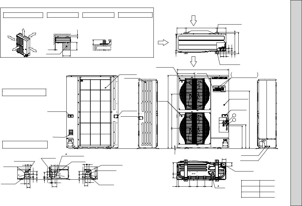
1 FREE SPACE (Around the unit)
The diagram below shows a basic example.
Explantion of particular details is given in the installation manuals etc.
|
|
FREE |
|
150mm |
Over |
|
Over |
||
|
10mm |
|
|
|
|
|
|
|
|
Over |
1000mm |
|
Over |
|
|
|
|
10mm |
|
2 SERVICE SPACE
Dimensions of space needed for service access are shown in the below diagram.
|
Over 150 |
Over |
Over 500 |
10 |
|
Service space |
Over |
|
500 |
3 FOUNDATION BOLTS
Please secure the unit firmly with 4 foundation (M10) bolts. (Bolts and washers must be purchased locally.)
<Foundation bolt height>
than |
30 |
|
Less |
FOUNDATION |
4 PIPING-WIRING DIRECTIONS
Piping and wiring connections can be made from 4 directions: front, right, rear and below.
Rear Air Intake
Side Air Intake
Example of Notes
 ···Refrigerant GAS pipe connction (FLARE)
 15.88(5/8 inch)
 ···Refrigerant LIQUID pipe connection (FLARE)
 9.52(3/8 inch)
  1 ···Indication of STOP VALVE connection location.
Handle for moving |
Handle for moving |
Handle for moving
Air intake
Piping Knockout Hole Details
Power supply wiring hole (2- 27Knockout)
Front trunking hole |
40 |
45 |
|
(Knockout) |
|||
|
|
|
|
55 |
|
|
|
92 |
|
63 |
|
|
|
73 |
||
Front piping hole |
|
|
||
92 |
27 |
23 |
||
(Knockout) |
||||
|
|
|||
|
|
65 |
|
Right piping hole (Knockout)
75
|
63 |
|
|
27 92 |
|
19 |
|
23 |
73 |
||
|
92
Power supply wiring hole |
|
|
||
(2- |
27Knockout) |
|
|
|
|
Right trunking hole |
|
||
|
(Knockout) |
|
|
|
40 |
|
|
45 |
40 |
|
|
55 |
|
|
92 |
63 |
|
|
92 |
|
|
|
||
|
73 |
|
|
|
55 |
23 |
27 |
65 |
92 |
|
|
|||
|
|
|
|
|
Power supply wiring hole (2- 27Knockout)
Rear trunking hole (Knockout)
Rear piping hole (Knockout)
175
Side Air Intake
30 330
Handle for moving
322
Handle for moving
1350 |
635 |
371
23
81 219
30 220
Rear Air Intake |
2-U Shaped notched holes |
|
|
|
(Foundation Bolt M10) |
600 |
175 |
Installation Feet |
(19) |
|
45 |
56 |
370 |
417 |
|
66 |
42 |
53 |
28 |
Air Discharge |
|
|
||
2-12 x 36 Oval holes |
||||
|
(Foundation Bolt M10) |
|||
|
950 |
|
|
|
|
|
|
Earth terminal |
|
|
Terminal connection |
||
|
|
|
Left ····Power supply wiring |
|||
|
|
|
|
|
||
|
|
|
|
|
Right··· Indoor/Outdoor wiring |
|
|
|
|
|
|
Service panel |
|
|
|
|
|
|
Handle for moving |
|
|
|
|
|
|
1 |
|
|
|
|
|
|
2 |
A |
|
|
|
|
|
|
|
|
|
|
|
|
443 |
447 |
|
|
|
|
|
+1 |
+1 |
|
|
|
|
|
|
Front piping cover |
|
|
|
|
71 |
Rear piping cover |
|
|
|
|
|
|
||
|
|
|
|
|
71 |
|
|
|
|
|
|
Bottom piping hole |
|
|
|
|
|
|
(Knockout) |
|
145 |
145 |
145 |
Drain hole |
|
|
|
(5- |
33) |
|
|
|||
|
|
|
|
HRP·VHA2 |
||
|
|
|
|
|
|
|
HRP·YHA2
HRP71VHA2-PUHZ HRP100VHA2-PUHZ HRP100YHA2-PUHZ HRP125YHA2-PUHZ
A |
|
1,079 |
Unit |
930 |
|
|
mm : |
|
8 
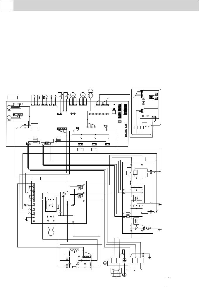
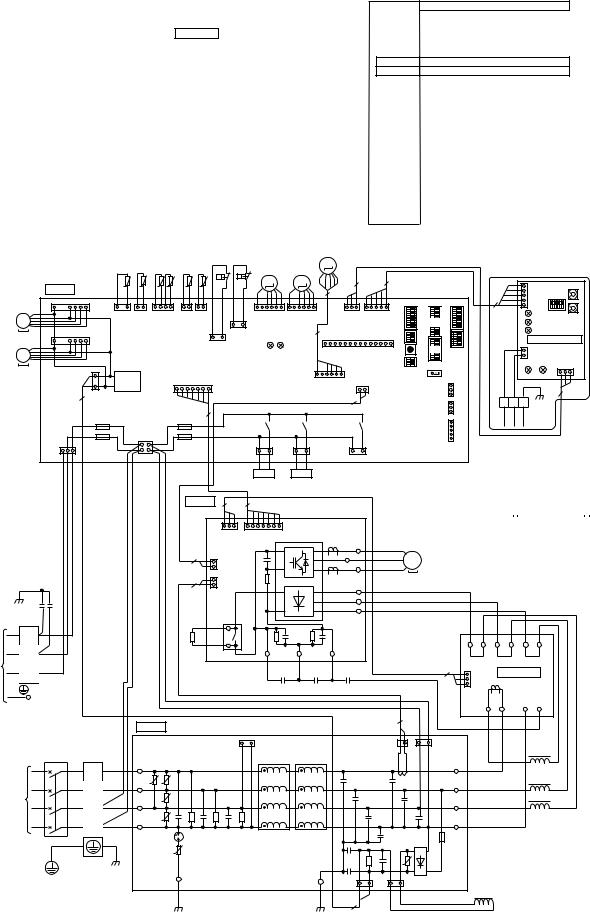
 WIRING DIAGRAM
PUHZ-HRP71VHA |
PUHZ-HRP100VHA |
|
|
|
|||||
|
[LEGEND] |
|
|
|
|
|
|
|
|
|
SYMBOL |
NAME |
|
SYMBOL |
NAME |
SYMBOL |
NAME |
||
|
TB1 |
Terminal Block<Power Supply, Indoor/Outdoor> |
P.B. |
Power Circuit Board |
|
SW6 |
Switch<Model Select> |
||
|
MC |
Motor for Compressor |
|
|
TABU/V/W |
Connection Terminal<U/V/W-Phase> |
|
SW7 |
Switch<Function Setup> |
|
MF1, MF2 |
Fan Motor |
|
|
TABS/T |
Connection Terminal <L/N-Phase> |
|
SW8 |
Switch<Function Setup> |
|
21S4 |
Solenoid Valve (Four-Way Valve) |
|
TABP1/P2/P |
Connection Terminal<DC Voltage> |
|
SW9 |
Switch |
|
|
63H |
High Pressure Switch |
|
|
TABN1/N2/N |
Connection Terminal<DC Voltage> |
|
SWP |
Switch<Pump Down> |
|
63L |
Low Pressure Switch |
|
|
DS2, DS3 |
Diode Bridge |
|
CN31 |
Connector<Emergency Operation> |
|
SV |
Solenoid Valve (Bypass Valve) |
|
IPM |
Power Module |
|
SS |
Connector<Connection for Option> |
|
|
TH3,TH32,TH33 |
Thermistor<Outdoor Pipe> |
|
N.F. |
Noise Filter Circuit Board |
|
CNM |
Connector<A-Control Service Inspection Kit> |
|
|
TH4 |
Thermistor<Discharge> |
|
|
LI / LO |
|
|
CNMNT |
Connector |
|
|
|
Connection Terminal<L-Phase> |
||||||
|
TH6 |
Thermistor<Outdoor 2-Phase Pipe> |
|
NI / NO |
Connection Terminal<N-Phase> |
|
|
<Connected to Optional M-NET Adapter Board> |
|
|
TH7 |
Thermistor<Outdoor> |
|
|
EI, E2 |
Connection Terminal<Ground> |
|
CNVMNT |
Connector |
|
TH8 |
Thermistor<Heatsink> |
|
|
52C |
52C Relay |
|
|
<Connected to Optional M-NET Adapter Board> |
|
LEV-A, LEV-B,LEV-C |
Electronic Expansion Valve |
|
C.B. |
Controller Circuit Board |
|
CNDM |
Connector |
|
|
DCL |
Reactor |
|
|
SW1 |
Switch<Forced Defrost, Defect History Record |
|
|
< Connected for Option (Contact Input)> |
|
ACTM |
Active Filter Module |
|
|
|
Reset, Refrigerant Address> |
|
LED1,LED2 |
LED<Operation Inspection Indicators> |
|
CB |
Main Smoothing Capacitor |
|
|
SW4 |
Switch<Test Operation> |
|
F1~F4 |
Fuse< T6.3AL250V> |
|
CY1,CY2 |
Capacitor |
|
|
SW5 |
Switch<Function Switch> |
|
X51,X52,X55 |
Relay |
LEV-C |
When M-NET adapter is connected |
|
63H 63L
TH33 TH32 TH7 TH6 TH3 TH4
C. B. |
t° |
t° |
t° t° |
t° |
t° |
|
|||||
7 |
CNF1 |
|
|
|
|
MF1 1 |
(WHT) 1 3 |
|
|
|
|
MS |
1 2 |
1 4 |
1 2 |
2 1 |
|
3~ |
TH33 TH32 |
TH7/6 |
TH3 TH4 |
||
|
(YLW) |
(BLK) |
(RED) |
(WHT) (WHT) |
|
MF2 |
7 |
CNF2 |
|
|
|
1 3 |
1 |
(WHT) |
|
1 |
3 |
63L |
|
MS |
|
|
(RED) |
|||
|
|
|
63H |
|||
3~ |
|
|
|
(YLW) |
|
|
|
|
|
|
|
||
|
|
3 |
|
|
CN2 |
|
|
2 |
TRANS |
|
1 |
(WHT) 7 |
|
|
CNDC(PNK) 1 |
|
|
|
|
|
|
|
F2 |
|
F3 |
|
7 |
|
|
CNAC |
|
|
||
|
|
|
(WHT) |
|
|
|
LEV-A |
|
LEV-B |
M |
|
|
|
|
M |
|
M |
|
|
3 |
|
|
|
|
|
|
|
|
5 |
|
|
|
|
5 |
|
|
|
|
|
|
|
|
|
|
|
|
1 |
6 |
1 |
6 |
1 |
3 |
1 |
5 |
LEV-A |
|
LEV-B |
|
CNVMNT CNMNT |
|||
(WHT) |
LED1 |
(RED) |
|
(WHT) |
(WHT) |
||
LED2 |
|
1 |
CNM |
|
14 |
||
|
|
|
|
||||
|
|
|
5 |
(WHT) |
|
|
|
|
|
|
|
|
CN52C |
||
|
CN4 |
|
|
|
|||
|
|
|
|
(RED) |
|||
(WHT) |
|
|
|
1 |
2 |
||
|
2 |
1 |
|
|
|
|
|
2 |
|
|
1 LEV-C 6 |
|
2 |
|
|
|
|
|
(BLU) |
|
|
|
|
|
|
X52 |
|
X55 |
|
|
|
+1 SW5 


SW4 SW8SWP
X51
|
|
|
|
|
5 |
|
|
SW11 |
|
|
|
|
|
CN5 |
SW1 |
|
|
|
|
|
5 |
|
(WHT) |
|
||
|
|
|
|
1 |
|
|
|
|
|
|
|
|
|
|
|
|
|
|
|
|
|
|
LED2 |
|
SW12 |
|
+1 |
|
|
|
|
LED3 |
|
||
|
|
|
|
|
|
|||
|
|
|
|
LED4 |
|
|
||
|
SW7 |
|
|
|
|
|
||
SW6 |
|
|
2 |
M-NET SUBSTRATE |
||||
|
SW9 |
|
|
|
CN2M |
|
CND |
|
SW1 |
|
|
1 |
(WHT) |
|
|||
|
|
LED1 |
(WHT) |
|||||
|
|
|
LED5 |
3 |
1 |
|||
|
|
|
|
|
|
|
||
CN31 |
|
|
|
|
|
|
|
|
CNDM |
(WHT) |
3 |
A B |
S |
|
|
3 |
|
|
|
1 |
|
|
|
|
|
|
CN51 (WHT) |
1 |
|
|
TB7 |
|
|
|
|
|
|
|
M-NET |
|
|
|||
|
|
|
|
|
|
|
||
|
|
5 |
|
|
|
|
|
|
CNS |
F1 |
1 |
2 |
21S4 3 |
1 |
3 |
1 SV2 |
3 |
1 SS |
|
|
(WHT) |
|
F4 |
|
|
|||||||
3 |
1 |
3 |
4 |
(GRN) |
|
|
(BLU) |
|
(WHT) |
|
|
|
|
|
|
21S4 |
|
|
SV |
|
|
|
|
|
|
|
|
|
|
|
|
|
WHT |
BLU |
|
|
|
|
|
|
|
|
|
|
N. F. |
|
|
|
|
|
|
|
|
|
|
|
|
|
|
|
|
|
|
|
|
|
|
|
LO |
NO |
|
|
|
|
|
|
|
|
|
|
52C |
1 |
2 |
|
|
|
|
|
|
|
|
|
2 |
|
|
|
|
|
|
|
|
|
|
|
|
CN52C |
|
|
P. B. |
|
|
|
|
|
|
|
|
(BLK) |
|
|
|
|
|
|
|
|
|
|
|
|
4 |
1 |
|
|
|
|
|
|
DS3 |
TABT |
BLU |
|
|
|
|
|
|
CNAF |
|
|
CNDC |
|
|
|
|
|
3 |
|
|
|
|
|
|
(WHT) |
|
|
2 |
|
|
|
|
|
|
|
|
|||
7 |
6 |
|
|
|
(PNK) |
|
|
TABS |
WHT |
|
|
|
|
|
|
1 |
|
|
|
1 |
|
|
DS2 |
|
|
|
|
|
|||
|
CN2 |
|
|
|
|
|
|
|
|
1 |
|
|
|
|
|
|
|
IPM |
|
3 |
|
|
|
|
|
|
|
|
|
||
|
(WHT) |
|
|
|
|
|
|
CNAC2 |
|
|
|
|
|||
|
7 |
TABP2 |
|
|
|
|
|
|
TABP1 |
RED |
(RED) |
|
|
|
|
|
|
|
|
|
|
|
|
|
|
|
|
|
|||
|
|
|
|
|
|
|
|
|
|
|
|
|
|
||
TH8 |
1 |
CN5 |
RED |
|
TABN1 |
BLK |
|
|
|
|
|
|
|
BLK |
|
t° 2 |
|
|
|
|
|
|
|
|
|
||||||
|
1 |
CN3 |
|
|
|
|
|
|
|
|
|
|
|
E2 |
|
|
2 |
(WHT) |
|
|
|
|
|
U |
|
|
|
|
|
||
2 |
2 |
(RED) |
|
|
|
|
|
|
|
|
3 |
|
|
1 |
2 |
1 |
CN4 |
|
|
|
|
|
|
|
|
|
|
2 |
|
||
|
2 |
(WHT) |
|
|
|
|
|
|
|
|
|
|
|
|
|
WHT |
|
|
|
|
|
|
|
|
|
|
|
CN5 |
|||
TABN |
|
|
|
|
|
|
|
|
|
|
|
||||
CB |
TABU |
TABV |
TABW |
|
|
TABN2 |
|
|
1 |
|
|
(RED) |
|||
RED |
TABP |
|
|
|
|
CNAC1 |
|
|
|
|
|||||
|
|
RED |
WHT BLK |
|
|
|
WHT |
|
|
(WHT) |
|
|
|
|
|
|
|
|
|
|
|
|
|
|
|
|
|
BLK |
|||
|
|
|
|
U V |
W |
|
|
|
|
|
LI |
U |
NI |
U |
EI |
|
|
|
|
MS |
|
|
|
|
|
|
|
|
|
|
|
|
|
|
|
3~ |
MC |
|
|
|
|
|
|
RED |
|
BLU |
|
|
|
|
|
|
|
|
|
|
|
|
|
|
|
||
M-NET ADAPTER
SYMBOL |
NAME |
TB7 |
Terminal Block<M-net connection> |
CN5 |
Connector<Transmission> |
CND |
Connector<Power Supply> |
CN2M |
Connector<M-NET communication> |
SW1 |
Switch<Status of communication> |
SW11 |
Switch<Address setting : 1st digit> |
SW12 |
Switch<Address setting : 2nd digit> |
LED1 |
LED<Power Supply : DC5V> |
LED2 |
LED<Connection to Outdoor Unit> |
LED3 |
LED<Transmission : Sending> |
LED4 |
LED<Transmission : Recelving> |
LED5 |
LED<Power Supply : DC12V> |
DCL |
4 |
|
|
|
BLK |
WHT |
|
RED |
L1 |
L2 1 P 6 RED |
|
|
|
N1 |
|
BLK |
|
N2 |
WHT |
|
Io |
||
|
|
|
|
|
ACTM |
|
|
RED |
BLU |
GRN/YLW YLW |
ORN |
BRN |
CY1 |
|
|
|
|
|
|
|
|
|
|
|
CY2 |
L |
N |
S1 |
S2 |
S3 TB1 |
|
+1MODEL SELECT
INDOOR |
MODEL |
|
|
|
|
|
|
|
SW6 |
|
|
SW5-6 +2 |
||||||||||||||||||||||||||||
UNIT |
71V |
ON |
|
|
|
|
|
|
|
|
|
|
|
|
|
|
|
|
|
|
|
ON |
|
|
|
|
|
|
|
|
|
|
|
|
|
|
|
|
|
|
POWER SUPPLY |
OFF |
|
|
|
|
|
|
|
|
|
|
|
|
|
|
|
|
|
|
|
OFF |
|
|
|
|
|
|
|
|
|
|
|
|
|
|
|
|
|
|
|
~/N 230V 50Hz |
|
|
1 2 3 4 5 6 7 8 |
|
|
|
1 2 3 4 5 6 |
|
|
|||||||||||||||||||||||||||||||
|
|
|
|
|
|
|
|
|
|
|
|
|
|
|
|
|
|
|
|
|
|
|
|
|
|
|
|
|
|
|
|
|
|
|
|
|
||||
|
100V |
ON |
|
|
|
|
|
|
|
|
|
|
|
|
|
|
|
|
|
|
|
ON |
|
|
|
|
|
|
|
|
|
|
|
|
|
|
|
|
|
|
|
|
|
|
|
|
|
|
|
|
|
|
|
|
|
|
|
|
|
|
|
|
|
|
|
|
|
|
|
|
|
|
|
||||||||
|
OFF |
|
|
|
|
|
|
|
|
|
|
|
|
|
|
|
|
|
|
|
OFF |
|
|
|
|
|
|
|
|
|
|
|
|
|
|
|
|
|
|
|
|
|
|
|
|
1 |
|
2 |
|
3 |
|
4 |
|
5 |
|
6 |
|
7 |
|
8 |
|
|
|
|
1 |
|
|
3 |
|
4 |
|
5 |
|
6 |
|
|
|||||
|
|
|
|
|
|
|
|
|
|
|
|
|
|
|
|
|
|
|
|
|
|
|
|
|
|
|
|
|
|
|
|
|
|
|
|
|
|
|
|
|
+2. SW5 -1 to 5 : Function Switch
14
|
|
|
|
|
|
|
|
|
|
|
|
|
|
|
|
|
|
|
|
PUHZ-HRP100YHA |
PUHZ-HRP125YHA |
|
|
|
|
|
|
|
|||||||||||
[LEGEND] |
|
|
|
|
|
|
|
|
|
|
|
|
|
|
|
|
|||
|
SYMBOL |
NAME |
|
|
|
SYMBOL |
|
|
NAME |
|
SYMBOL |
NAME |
|
||||||
|
TB1 |
|
Terminal Block<Power Supply> |
|
|
|
P.B. |
Power Circuit Board |
|
|
C.B. |
Controller Circuit Board |
|||||||
|
TB2 |
|
Terminal Block<Indoor/Outdoor > |
|
|
TB-U/V/W |
Connection Terminal<U/V/W-Phase> |
|
SW1 |
Switch<Forced Defrost, Defect History Record |
|
|
|||||||
|
MC |
|
Motor for Compressor |
|
|
|
|
TB-L1/L2/L3 |
Connection Terminal<L1/L2/L3-Power Supply> |
|
|
Reset, Refrigerant Adress> |
|
||||||
|
MF1, MF2 |
|
Fan Motor |
|
|
|
|
TB-P2 |
Connection Terminal |
|
|
|
SW4 |
Switch<Test Operation> |
|
|
|||
|
21S4 |
|
Solenoid Valve (Four-Way Valve) |
|
|
TB-C1 |
Connection Terminal |
|
|
|
SW5 |
Switch<Function Switch> |
|
|
|||||
|
63H |
|
High Pressure Switch |
|
|
|
|
TB-N1 |
Connection Terminal |
|
|
|
SW6 |
Switch<Model Select> |
|
|
|||
|
63L |
|
Low Pressure Switch |
|
|
|
|
X52A |
52C Relay |
|
|
|
SW7 |
Switch<Function Setup> |
|
|
|||
|
SV |
|
Solenoid Valve (Bypass Valve) |
|
|
|
N.F. |
Noise Filter Circuit Board |
|
|
SW8 |
Switch<Function Setup> |
|||||||
|
TH3,TH32,TH33 |
Thermistor<Outdoor Pipe> |
|
|
|
|
LI1/LI2/LI3/NI |
Connection Terminal<L1/L2/L3/N-Power Supply> |
|
|
|
|
|
||||||
|
|
|
|
|
|
SW9 |
Switch |
|
|
||||||||||
|
TH4 |
|
Thermistor<Discharge> |
|
|
|
|
LO1/LO2/LO3/NO |
Connection Terminal<L1/L2/L3/N-Power Supply> |
|
SWP |
Switch<Pump Down> |
|
|
|||||
|
TH6 |
|
Thermistor<Outdoor 2-Phase Pipe> |
|
|
GD1, GD3 |
Connection Terminal<Ground> |
|
|
CN31 |
Connector<Emergency Operation> |
|
|
||||||
|
TH7 |
|
Thermistor<Outdoor> |
|
|
|
|
CONV.B. |
Converter Circuit Board |
|
|
|
LED1, LED2 |
LED<Operatiion Inspection Indicators> |
|
|
|||
|
LEV-A, LEV-B, LEV-C |
Electronic Expansion Valve |
|
|
|
|
L1-A1/IN |
Connection Terminal<L1-Power Supply> |
|
F1~F4 |
Fuse<T6.3AL250V> |
|
|||||||
|
ACL1~ACL4 |
Reactor |
|
|
|
|
L1-A2/OU |
Connection Terminal<L1-Power Supply> |
|
CNM |
Connector<A-Control Service Inspection Kit> |
|
|
||||||
|
CB1, CB2 |
|
Main Smoothing Capacitor |
|
|
|
|
L2-A2/OU |
Connection Terminal<L2-Power Supply> |
|
CNMNT |
Connector |
|
||||||
|
CK |
|
Capacitor |
|
|
|
|
L3-A2/OU |
Connection Terminal<L3-Power Supply> |
|
|
<Connect to Optional M-NET Adapter Board> |
|
||||||
|
CY1, CY2 |
|
Capacitor |
|
|
|
|
N-IN |
Connection Terminal |
|
|
|
CNVMNT |
Connector |
|
|
|||
|
RS |
|
Rush Current Protect Resistor |
|
|
|
|
CK-OU |
Connection Terminal |
|
|
|
|
<Connect to Optional M-NET Adapter Board> |
|
||||
|
M-NET ADAPTER |
|
|
|
|
|
|
|
|
|
|
|
CNDM |
Connector |
|
|
|||
|
|
|
|
|
|
|
|
|
|
|
|
|
< Connection for Option(Contact Input)> |
|
|||||
|
TB7 |
|
Terminal Block<M-NET connection > |
|
SW12 |
Switch<Address setting. 2nd digit > |
|
|
|
|
CN3S |
Connector< Connection for Option> |
|
|
|||||
|
CN5 |
|
Connector<Transmission> |
|
LED1 |
LED<Power Supply: DC5V> |
|
|
|
|
CN51 |
Connector< Connection for Option> |
|
|
|||||
|
CND |
|
Connector<Power Supply> |
|
LED2 |
LED<Connection to Outdoor Unit> |
|
|
|
|
SS |
Connector< Connection for Option> |
|
|
|||||
|
CN2M |
|
Connector<M-NET communication> |
|
LED3 |
LED<Transmission: Sending> |
|
|
|
|
X51,X52,X55 |
Relay |
|
|
|||||
|
SW1 |
|
Switch<Status of communication> |
|
LED4 |
LED<Transmission: Receiving> |
|
|
|
|
|
|
|
|
|||||
|
SW11 |
|
Switch<Address setting: 1st digit> |
|
LED5 |
LED<Power Supply: DC12V> |
|
|
|
|
|
|
|
|
|||||
|
|
|
|
|
|
|
|
|
|
|
63L |
|
LEV-C |
|
|
|
|
|
|
|
|
|
|
|
|
|
|
|
63H |
|
M |
|
|
|
|
|
|||
|
|
|
|
TH33 TH32 TH7 TH6 TH3 TH4 |
|
LEV-A |
LEV-B |
|
|
When M-NET adapter is connected) |
|||||||||
|
|
|
|
|
|
|
|
||||||||||||
|
C . B . |
|
|
t° |
t° |
|
t° t° |
t° |
t° |
|
|
|
MF1 |
1 |
|
|
CNF1 |
|
|
|
|
|
|
|
|
|
|
7 (WHT) 1 3 |
1 2 |
|
1 |
4 |
1 2 |
2 1 |
|
|
||
MS |
|
|
|
|
|
|||||||
|
|
|
TH33 |
TH32 |
TH7/6 |
TH3 |
TH4 |
|
|
|||
3~ |
|
|
|
(YLW) |
(BLK) |
(RED) |
(WHT) |
(WHT) |
1 |
3 |
||
|
|
|
|
|||||||||
|
|
|
|
|
|
|
|
|
|
|
||
MF2 |
1 |
|
|
CNF2 |
|
|
|
|
|
|
63L |
|
|
7 |
(WHT) |
|
|
|
|
|
1 3 |
(RED) |
|||
|
|
|
|
|
|
|
||||||
MS |
|
|
|
|
|
|
|
|
63H |
|
|
|
3~ |
|
|
|
|
|
|
|
|
|
(YLW) |
|
|
|
|
|
3 |
|
|
|
|
|
CN2 |
|
|
|
|
|
|
1 |
TRANS |
|
|
|
1 (WHT) 7 |
|
|
||
|
|
2 |
|
|
|
|
|
|
|
|
|
|
|
|
CNDC |
|
|
|
|
|
|
|
|
||
|
|
|
(PNK) |
|
|
|
|
|
|
|
|
|
|
|
|
|
|
|
|
|
|
|
7 |
|
|
|
|
|
|
F2 |
CNAC |
|
|
F3 |
|
|
|
|
|
|
|
|
|
|
|
|
|
|
|
||
|
|
|
|
|
(WHT) |
|
|
|
|
|
|
|
|
CNS |
|
|
F1 |
1 |
2 |
|
|
F4 |
|
|
|
|
|
|
|
|
|
|
|
|
|
|||
|
(WHT) |
|
|
|
|
|
|
|
|
|
|
|
|
3 |
1 |
|
|
3 |
4 |
|
|
|
|
|
|
|
|
|
|
BLK |
BLU |
|
|
|
|
|
|
|
|
M |
|
|
M |
|
3 |
|
5 |
|
|
|
|
|
5 |
|
|
|
|
|
|
|
|
|
|
|
|
|
|
+1 |
1 |
6 |
1 |
|
6 |
1 |
3 |
1 |
5 |
SW5 |
LEV-A |
|
LEV-B |
CNVMNT CNMNT |
||||||
(WHT) |
|
(RED) 5 |
(WHT) |
|
(WHT) |
SWP SW8 |
|||
LED2 |
|
LED1 |
|
1 |
|
CNM |
14 |
||
|
|
|
|
|
(WHT) |
|
SW4 |
||
|
|
|
|
|
|
|
|
|
|
|
|
|
|
|
|
CN4 |
|
|
|
|
|
|
|
1 LEV-C 6 |
(WHT) |
|
|||
|
|
|
|
1 |
2 |
|
|
||
|
|
|
|
(BLU) |
2 |
|
|
|
|
|
|
|
|
|
|
|
|
||
|
X52 |
|
|
X55 |
|
|
X51 |
|
|
3 |
1 21S4 3 |
1 SV2 |
3 |
|
1 |
SS |
|
||
|
(GRN) |
|
(BLU) |
|
|
|
(WHT) |
|
|
+1 SW6 


SW1  CN31
CN31
CN51 CNDM CN3S (WHT) (WHT) (WHT)
5 |
|
|
5 |
CN5 |
(WHT) |
|
|
SW11 |
|
|
|
|
SW1 |
|
|||||
|
|
|
1 |
|
|
|
|
|
|
SW7 |
|
|
|
LED2 |
|
SW12 |
|||
|
|
|
LED3 |
|
|||||
|
|
|
|
|
|||||
|
|
|
|
|
|
||||
SW9 |
|
|
|
LED4 |
|
|
|||
|
|
M-NET SUBSTRATE |
|||||||
|
|
|
LED5 |
|
(WHT) |
LED1 |
|
|
|
|
|
|
2 |
CN2M |
|
|
CND |
||
|
|
|
1 |
|
|
|
|
||
|
|
|
|
|
|
|
|
(WHT) |
|
|
|
|
|
|
|
|
|
3 |
1 |
1 |
|
|
|
|
|
|
|
3 |
|
3 |
|
|
|
|
|
|
|
|
|
A |
B |
S |
|
|
|
|
|
|
|
1 |
|
|
|
|
|
|
|||
3 |
|
|
TB7 |
|
|
|
|
|
|
1 |
|
|
M-NET |
|
|
|
|||
|
|
|
|
|
|
||||
5
21S4 SV
CY1 |
CY2 |
TB2
S1
S2
INDOOR
UNIT S3
BRN ORN YLW
|
P . B . 3 |
|
|
7 |
|
|
|
|
|
1 |
3 |
1 |
CN2 |
7 |
|
|
|
|
|
CN7 |
|
(WHT) |
|
|
|
|
|
(WHT) |
|
+ |
|
TB-W |
|||
|
|
|
|
|||||
2 |
2 |
|
CN4 |
|
|
|
|
TB-V |
|
|
|
|
|
|
|||
|
1 |
(WHT) |
|
|
-- |
|
TB-U |
|
|
2 |
|
CN5 |
|
|
|
||
2 |
|
|
|
|
|
|||
1 |
(RED) |
|
|
+ |
|
TB-L3 |
||
|
|
|
|
|||||
|
|
|
|
|
|
|
|
TB-L2 |
|
|
|
|
|
|
-- |
|
TB-L1 |
|
REDX52A |
|
|
|
|
|||
|
|
|
+ |
|
|
|||
RS |
|
|
|
|
|
+ |
|
|
|
|
|
|
|
|
|
||
|
|
|
|
|
|
|
|
|
|
RED |
|
|
|
|
TB-P2 |
TB-C1 |
TB-N1 |
|
|
|
|
|
|
|||
|
|
|
|
|
RED |
WHT |
+CB2 |
BLK |
|
|
|
|
|
|
+CB1 |
CK |
|
N . F .
BLK |
W MC |
|
WHT |
V |
MS |
|
U |
3~ |
RED
BLK
WHT
RED
2
POWER SUPPLY 3N~
400V 50Hz
CNAC1 |
|
(WHT) 1 |
3 |
TB1 |
|
LI1 |
|
|
L1 |
RED |
|
|
|
|
|
|
||
|
|
|
|
|
L2 |
WHT |
LI2 |
U |
U |
|
|
|
|
|
L3 |
BLK |
LI3 |
|
U |
|
|
|||
|
|
|
|
|
N |
BLU |
NI |
|
U |
|
|
|||
|
|
|
|
|
|
GRN/YLW |
|
|
|
|
|
|
|
U |
|
GD1 |
GD3 |
|
|
|
BLK |
|
BLK |
CNCT 
 (RED) 1 2 1
|
|
+ |
+ |
|
|
|
|
|
|
|
U -- |
CNDC 1 |
3 |
3 |
1 CNL |
(PNK) |
|
|
(BLU) |
2 |
|
WHT |
WHT |
+1MODEL SELECT
MODEL |
|
|
|
|
SW6 |
|
|
SW5-6 +2 |
||||||||||||||||||||||||
100Y |
ON |
|
|
|
|
|
|
|
|
|
|
|
|
|
|
|
|
|
ON |
|
|
|
|
|
|
|
|
|
|
|
|
|
OFF |
|
|
|
|
|
|
|
|
|
|
|
|
|
|
|
|
|
OFF |
|
|
|
|
|
|
|
|
|
|
|
|
|
|
|
|
1 |
|
2 |
|
3 |
|
4 |
|
5 |
|
6 |
|
7 |
|
8 |
|
|
|
1 |
|
2 |
|
3 |
|
4 |
|
5 |
|
|
|
|
|
|
|
|
|
|
|
|
|
|
|
|
|
|
|
|
|
||||||||||||||||
125Y |
ON |
|
|
|
|
|
|
|
|
|
|
|
|
|
|
|
|
|
ON |
|
|
|
|
|
|
|
|
|
|
|
|
|
OFF |
|
|
|
|
|
|
|
|
|
|
|
|
|
|
|
|
|
OFF |
|
|
|
|
|
|
|
|
|
|
|
|
||
|
|
1 |
|
2 |
|
3 |
|
4 |
|
5 |
|
6 |
|
7 |
|
8 |
|
|
|
1 |
|
2 |
|
3 |
|
4 |
|
5 |
|
|
|
|
|
|
|
|
|
|
|
|
|
|
|
|
|
|
|
|
|
|
|
|
|
|
|
|
|
|
|
|
|
|
|
|
|
+2. SW5 -1 to 5 : Function Switch
BLK |
BLK |
WHT |
WHT |
RED |
RED |
|
|
L3-OU |
L3-A2 |
L2-OU |
L2-A2 |
L1-OU |
L1-A2 |
3 |
3 |
|
CONV.B. |
|
|
|
1CN7(WHT) |
|
|
|
|
|
L1-A1 |
|
L1-IN |
N-IN |
CK-OU |
|
|
|
|
|
BLK |
CNAC2 |
RED |
RED |
|
BLU |
|
|
|
|
|
|
|
3 (RED) |
|
|
|
ACL1 |
|
|
|
|
|
||
LO1 RED
ACL2
LO2 WHT
ACL3
LO3 BLK
NO BLU
ACL4
15
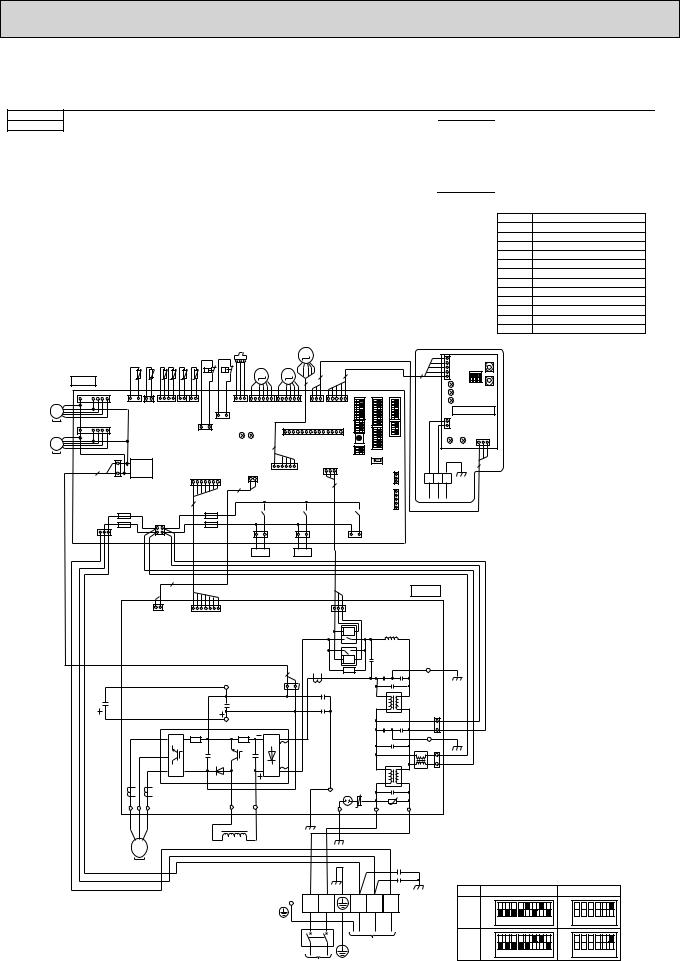
PUHZ-HRP71VHA2 PUHZ-HRP100VHA2
[LEGEND] |
|
|
|
|
|
|
|
SYMBOL |
NAME |
SYMBOL |
NAME |
||||
TB1 |
Terminal Block<Power Supply, Indoor/Outdoor> |
P.B. |
Power Circuit Board |
||||
MC |
Motor for Compressor |
|
U/V/W |
Connection Terminal<U/V/W-Phase> |
|||
MF1, MF2 |
Fan Motor |
|
LI |
Connection Terminal <L-Phase> |
|||
21S4 |
Solenoid Valve (Four-Way Valve) |
|
NI |
Connection Terminal<N-Phase> |
|||
SV |
Solenoid Valve (Bypass Valve) |
|
DCL1, DCL2 |
Recator |
|||
63H |
High Pressure Switch |
|
IGBT |
Power Module |
|||
63L |
Low Pressure Switch |
|
E1,E2,E3,E4 |
Connection Terminal (Ground) |
|||
63HS |
High Pressure Sensor |
C.B. |
Controller Circuit Board |
||||
TH3 |
Thermistor<Liquid> |
|
SW1 |
Switch<Forced Defrost, Defect History Record |
|||
TH4 |
Thermistor<Discharge> |
|
|
Reset, Refrigerant Address> |
|
||
TH6 |
Thermistor<2-Phase> |
|
SW4 |
Switch<Test Operation> |
|||
TH7 |
Thermistor<Ambient> |
|
SW5 |
Switch<Function Switch> |
|||
TH32 |
Thermistor<Suction> |
|
SW6 |
Switch<Model Select> |
|||
TH33 |
Thermistor<Ref. check> |
|
SW7 |
Switch<Function Setup> |
|||
LEV-A, LEV-B,LEV-C |
Electronic Expansion Valve |
|
SW8 |
Switch<Function Setup> |
|
|
|
DCL |
Reactor |
|
SW9 |
Switch |
|||
CB |
Main Smoothing Capacitor |
|
SWP |
Switch<Pump Down> |
|||
CY1,CY2 |
Capacitor |
|
CN31 |
Connector<Emergency Operation> |
|||
SYMBOL |
NAME |
SS |
Connector<Connection for Option> |
CNM |
Connector<A-Control Service Inspection Kit> |
CNDM |
Connector |
|
< Connected for Option (Contact Input)> |
LED1,LED2 |
LED<Operation Inspection Indicators> |
F1~F4 |
Fuse< T6.3AL250V> |
X51,X52,X55 |
Relay |
M-NET ADAPTER
SYMBOL |
NAME |
TB7 |
Terminal Block<M-NET connection> |
CN5 |
Connector<Transmission> |
CND |
Connector<Power Supply> |
CN2M |
Connector<M-NET communication> |
SW1 |
Switch<Status of communication> |
SW11 |
Switch<Address setting : 1st digit> |
SW12 |
Switch<Address setting : 2nd digit> |
LED1 |
LED<Power Supply : DC5V> |
LED2 |
LED<Connection to Outdoor Unit> |
LED3 |
LED<Transmission : Sending> |
LED4 |
LED<Transmission : Recelving> |
LED5 |
LED<Power Supply : DC12V> |
LEV-C |
When M-NET adapter is connected |
|
|
|
|
|
|
|
|
|
63H |
63L |
|
|
|
|
|
TH33 TH32 TH7 TH6 TH3 TH4 |
|
|
|||||
|
|
C . B . |
|
t° |
t° |
t° |
t° |
t° |
t° |
|
|
MF1 |
1 |
|
CNF1 |
|
|
|
|
|
|
|
|
|
7 (WHT) |
1 3 |
1 2 |
1 |
4 |
1 2 |
2 1 |
|
|
||
MS |
|
|
|
||||||||
|
|
|
TH33 |
TH32 |
TH7/6 |
TH3 |
TH4 |
|
|
||
3~ |
|
|
|
(YLW) |
(BLK) |
(RED) |
(WHT) (WHT) |
1 |
3 |
||
|
|
|
|
|
|
|
|
|
|
||
MF2 |
1 |
|
CNF2 |
|
|
|
|
|
1 3 |
63L |
|
7 |
(WHT) |
|
|
|
|
|
(RED) |
||||
|
|
|
|
|
|
||||||
MS |
|
|
|
|
|
|
|
63H |
|
|
|
3~ |
|
|
|
|
|
|
|
|
(YLW) |
|
|
|
|
|
3 |
|
|
|
|
|
CN2 |
|
|
|
|
2 |
|
TRANS |
|
|
|
|
|
||
|
|
1 |
|
|
|
1 (WHT) |
7 |
|
|||
|
|
|
|
|
|
|
|
|
|||
|
|
|
CNDC |
|
|
|
|
|
|
|
|
|
|
|
(PNK) |
|
|
|
|
|
|
|
|
|
|
|
|
|
|
|
|
|
7 |
|
|
|
|
|
F2 |
|
CNAC |
|
|
F3 |
|
|
|
|
|
|
|
|
(WHT) |
|
|
|
|
|
|
63HS |
|
|
|
|
|
M |
|
|
|
|
|
|
|
|
|
|
|
|
|
|
|
|
|
|
LEV-A |
|
LEV-B |
|
|
|
|
|
|
|
|
M |
|
M |
|
|
3 |
|
5 |
|
|
|
|
|
|
|
5 |
|
|
|
1 |
3 |
1 |
LEV-A |
6 |
1 |
6 |
1 |
3 |
1 |
5 |
63HS |
|
|
LEV-B |
|
CNVMNT CNMNT |
|||||
(WHT) |
|
(WHT) |
|
(RED) |
|
(WHT) (WHT) |
||||
LED2 |
|
|
LED1 |
5 |
1 |
|
CNM |
|
14 |
|
|
|
|
|
|
|
(WHT) |
|
|
||
|
|
|
|
|
|
|
|
CN52C |
||
|
|
CN4 |
|
|
|
|
|
(RED) |
||
|
(WHT) |
|
|
|
|
|
1 |
3 |
||
|
|
1 |
2 |
1 |
LEV-C 6 |
|
|
|
|
|
2 |
|
|
|
|
(BLU) |
|
|
|
|
3 |
|
|
|
|
|
|
|
|
|
|
|
|
|
|
X52 |
|
|
X55 |
|
|
|
|
|
|
|
|
|
|
|
5 |
|
|
SW11 |
|
|
|
|
|
|
|
CN5 |
SW1 |
|
|
|
|
|
|
5 |
|
|
(WHT) |
|
||
|
|
|
|
|
|
1 |
|
|
|
|
|
|
|
|
|
|
|
|
|
|
|
|
|
|
|
|
|
|
LED2 |
|
SW12 |
|
1 |
|
1 |
|
|
|
|
LED3 |
|
||
|
|
|
|
|
|
|
||||
SW5 |
|
SW7 |
|
|
|
|
LED4 |
|
|
|
SW6 |
|
|
|
2 |
M-NET SUBSTRATE |
|||||
SWPSW4SW8 |
SW1 |
SW9 |
|
|
|
|
CN2M |
LED1 |
CND |
|
|
|
|
|
LED5 |
||||||
|
|
|
|
|
|
1 |
(WHT) |
|
(WHT) |
|
|
|
|
|
|
|
|
|
|
3 |
1 |
|
|
CN31 |
|
|
|
|
|
|
|
|
|
|
CNDM WHT)( |
3 |
A |
B |
S |
|
|
3 |
|
|
|
|
|
|
|
|||||
|
|
|
1 |
|
|
|
|
|
|
|
|
|
CN51 (WHT) |
1 |
|
|
|
TB7 |
|
|
|
|
|
|
|
|
M-NET |
|
|
|||
|
|
|
|
|
|
|
|
|||
|
|
5 |
|
|
|
|
|
|
|
|
|
X51 |
|
|
|
|
|
|
|
|
|
|
|
|
|
|
|
|
|
|
|
|
CNS |
F1 |
1 |
2 |
21S4 3 1 |
3 1 SV2 |
3 1 SS |
(WHT) |
|
F4 |
||||
3 |
1 |
3 |
4 |
(GRN) |
(BLU) |
(WHT) |
21S4 SV
|
|
|
2 |
|
|
|
|
|
|
|
|
|
|
|
|
|
|
|
|
|
|
|
|
|
|
|
|
|
|
|
|
P. B. |
|
|
|
|
|
2 |
|
|
|
|
|
|
|
CN52C |
|
|
|
|
|
|
|
|
1 |
1 |
CN2 |
7 |
|
|
1 |
3 |
(RED) |
|
|
|
|
|
|
|
|
|
|
CN4 |
|
|
|
|
|
|
|
|
|
|
|||||
|
(WHT) |
|
(WHT) |
|
|
|
|
52C |
|
|
|
|
|
|
|
||
|
|
|
|
|
|
|
|
|
|
|
|
|
|
|
|
||
|
|
|
|
|
|
|
|
|
52C |
|
|
|
|
BLK |
|
|
|
|
|
|
|
|
|
2 |
|
|
|
|
|
|
|
|
|
|
|
|
|
|
|
|
|
|
|
|
|
|
|
|
E3 |
|
|
|
|
WHT |
|
|
|
|
|
CNDC |
|
|
|
|
|
|
|
|
|
|
|
|
|
|
|
|
|
|
|
|
|
|
|
|
|
|
|
||
|
|
|
|
N2 |
(PNK) |
|
|
|
|
|
|
|
|
|
|
|
|
CB |
|
|
|
|
|
3 |
1 |
|
|
|
|
|
|
|
|
|
|
|
|
|
|
|
|
|
|
|
|
|
|
|
CNAC2 |
|
|
|
|
|
|
|
|
|
|
|
|
|
|
|
|
|
|
|
|
|
|
|
|
|
|
|
|
|
|
|
|
|
|
|
|
(RED) |
|
|
|
RED |
|
|
|
|
P2 |
IGBT |
|
|
|
|
|
|
1 |
|
|
|
|
|
|
|
|
|
|
|
|
|
|
|
|
|
|
|
|||
|
|
|
|
|
|
|
|
|
|
|
|
|
|
3 |
BLK |
|
|
|
|
|
|
|
|
|
|
|
|
|
|
|
|
E2 |
|
|
|
|
|
|
|
|
|
|
|
|
|
|
|
|
|
1 |
|
|
|
|
|
|
|
|
|
|
|
|
|
|
|
|
|
|
RED |
|
|
|
|
|
|
|
|
|
|
|
|
|
|
|
|
3 |
WHT |
|
|
|
|
|
|
|
|
|
|
|
|
|
|
|
|
CNAC1 |
|
|
|
|
|
|
|
|
|
|
|
|
|
|
|
|
|
(WHT) |
|
|
|
|
|
|
|
|
|
|
|
E4 |
|
|
|
|
|
|
|
|
|
W V |
U |
|
|
|
DCL2 |
DCL1 |
|
EI |
|
U |
|
NI |
U |
LI |
|
|
|
|
|
|
|
|
|
|
|
|
|
|
|||||||
BLK WHT RED |
|
|
|
DCL |
|
BLK |
BLK |
|
|
|
|
|
|
|
|
|
|
|
|
|
|
|
|
|
|
|
|
|
|
|
|
|
|||
W V |
U |
|
|
|
|
|
|
|
|
|
|
|
|
|
|
|
|
MS |
|
|
|
|
|
|
|
|
|
|
|
|
|
|
|
|
|
3~ |
|
|
|
|
|
|
|
|
|
|
|
|
|
|
|
|
|
MC |
|
|
|
|
|
|
|
|
GRN/YLW YLW |
|
|
|
CY1 |
|
|
|
|
|
|
|
|
|
|
|
RED |
BLU |
ORN |
BRN |
|
MODEL |
SW6 |
SW5-6 2 |
|||
|
|
|
|
|
|
|
|
|
|
|
|
|
|
CY2 |
1MODEL SELECT |
|
|
|
|
|
|
|
|
|
|
|
|
|
|
|
|
|
|
||
|
|
|
|
|
|
|
L |
N |
|
S1 |
S2 |
S3 |
TB1 |
71V |
ON |
ON |
|
|
|
|
|
|
|
|
|
|
|
|
|
|
|
|
OFF |
OFF |
|
|
|
|
|
|
|
|
|
|
|
|
|
|
|
|
|
1 2 3 4 5 6 7 8 |
1 2 3 4 5 6 |
|
|
|
|
|
|
|
|
|
|
INDOOR |
|
|
100V |
ON |
ON |
||
|
|
|
|
|
|
|
|
|
|
|
|
OFF |
OFF |
||||
|
|
|
|
|
|
|
|
|
|
UNIT |
|
|
|
|
1 2 3 4 5 6 7 8 |
1 2 3 4 5 6 |
|
|
|
|
|
|
|
|
POWER SUPPLY |
|
|
|
|
|
2. SW5 -1 to 5 : Function Switch |
||||
|
|
|
|
|
|
|
~/N 230V 50Hz |
|
|
|
|
|
|
|
|
|
|
|
|
|
|
|
|
|
|
|
|
16 |
|
|
|
|
|
|
|
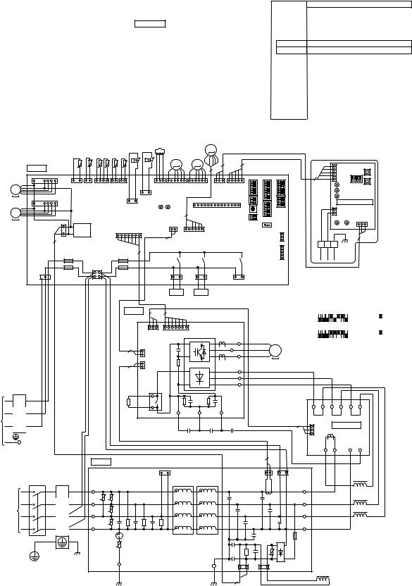
|
|
|
|
|
|
|
|
|
|
|
|
|
PUHZ-HRP100YHA2 |
PUHZ-HRP125YHA2 |
|
|
|
|
|
||||||
[LEGEND] |
|
|
|
|
|
|
|
|
|
|
|
|
|
SYMBOL |
NAME |
|
SYMBOL |
|
NAME |
SYMBOL |
NAME |
|
|||
|
TB1 |
Terminal Block<Power Supply> |
|
P.B. |
Power Circuit Board |
C.B. |
Controller Circuit Board |
|||||
|
TB2 |
Terminal Block<Indoor/Outdoor > |
|
TB-U/V/W |
Connection Terminal<U/V/W-Phase> |
|
SW1 |
Switch<Forced Defrost, Defect History Record |
|
|
||
|
MC |
Motor for Compressor |
|
|
TB-L1/L2/L3 |
Connection Terminal<L1/L2/L3-Power Supply> |
|
|
Reset, Refrigerant Adress> |
|
||
|
MF1, MF2 |
Fan Motor |
|
|
TB-P2 |
Connection Terminal |
|
SW4 |
Switch<Test Operation> |
|
|
|
|
21S4 |
Solenoid Valve (Four-Way Valve) |
|
TB-C1 |
Connection Terminal |
|
SW5 |
Switch<Function Switch> |
|
|
||
|
SV |
Solenoid Valve (Bypass Valve) |
|
|
TB-N1 |
Connection Terminal |
|
SW6 |
Switch<Model Select> |
|
|
|
|
63H |
High Pressure Switch |
|
|
X52A |
52C Relay |
|
|
SW7 |
Switch<Function Setup> |
|
|
|
63L |
Low Pressure Switch |
|
N.F. |
Noise Filter Circuit Board |
|
SW8 |
Switch<Function Setup> |
||||
|
63HS |
High Pressure Sensor |
|
|
LI1/LI2/LI3/NI |
Connection Terminal<L1/L2/L3/N-Power Supply> |
|
|
|
|
|
|
|
|
|
|
SW9 |
Switch |
|
|
|||||
|
TH3 |
Thermistor<Liquid> |
|
|
LO1/LO2/LO3/NO |
Connection Terminal<L1/L2/L3/N-Power Supply> |
|
SWP |
Switch<Pump Down> |
|
|
|
|
TH4 |
Thermistor<Discharge> |
|
|
GD1, GD3 |
Connection Terminal<Ground> |
|
CN31 |
Connector<Emergency Operation> |
|
|
|
|
TH6 |
Thermistor<Outdoor 2-Phase Pipe> |
|
CONV.B. |
Converter Circuit Board |
|
SS |
Connector< Connection for Option> |
|
|
||
|
TH7 |
Thermistor<Outdoor> |
|
|
L1-A1/IN |
Connection Terminal<L1-Power Supply> |
|
LED1, LED2 |
LED<Operatiion Inspection Indicators> |
|
||
|
TH32 |
Thermistor<Suction> |
|
|
L1-A2/OU |
Connection Terminal<L1-Power Supply> |
|
CNM |
Connector<A-Control Service Inspection Kit> |
|
|
|
|
TH33 |
Thermistor<Ref. chech> |
|
|
L2-A2/OU |
Connection Terminal<L2-Power Supply> |
|
CNDM |
Connector |
|
||
|
LEV-A, LEV-B, LEV-C |
Electronic Expansion Valve |
|
|
L3-A2/OU |
Connection Terminal<L3-Power Supply> |
|
|
< Connection for Option(Contact Input)> |
|
||
|
ACL1~ACL4 |
Reactor |
|
|
N-IN |
Connection Terminal |
|
F1~F4 |
Fuse<T6.3AL250V> |
|
|
|
|
RS |
Rush Current Protect Resistor |
|
|
CK-OU |
Connection Terminal |
|
X51,X52,X55 |
Relay |
|
|
|
|
CB1, CB2 |
Main Smoothing Capacitor |
|
|
|
|
|
|
|
|
|
|
|
CK |
Capacitor |
|
|
|
|
|
|
|
|
|
|
|
|
|
|
|
63HS |
|
LEV-C |
|
|
|
|
|
|
|
|
|
|
|
M |
|
|
|
|
|
|
|
|
|
|
63H 63L |
|
|
|
|
|
|
||
|
|
TH33 TH32 TH7 TH6 TH3 TH4 |
|
|
LEV-A |
LEV-B |
|
|
When M-NET adapter is connected |
|||
MF1
MS 3~
MF2
MS 3~
TB2
S1
S2
INDOOR
UNIT S3
C . B .
1
1 
2
CNS
(WHT)  3 1
3 1
YLW
ORN
BRN
M |
M |
3 |
5 |
t° t° t° t° t° t° |
|
5 |
|
|
CNF1 |
|
|
|
|
|
|
7 (WHT) 1 3 |
1 2 |
1 4 |
1 2 |
2 1 |
|
|
|
|
TH33 |
TH32 |
TH7/6 |
TH3 |
TH4 |
|
|
|
(YLW) |
(BLK) |
(RED) |
(WHT) (WHT) |
1 |
3 |
|
|
|
|
|
|
|
||
|
CNF2 |
|
|
|
1 3 |
63L |
|
7 |
(WHT) |
|
|
|
(RED) |
||
|
|
|
|
63H |
|
|
|
|
|
|
|
|
(YLW) |
|
|
|
3 |
|
|
|
CN2 |
|
|
|
TRANS |
|
1 |
(WHT) |
7 |
|
|
|
1 |
|
|
|
|
|
|
|
CNDC |
|
|
|
|
|
|
|
(PNK) |
|
|
|
|
|
|
|
|
|
|
|
7 |
|
|
|
F2 |
CNAC |
|
F3 |
|
|
|
|
|
|
|
|
|
||
|
|
(WHT) |
|
|
|
|
|
|
F1 |
1 |
2 |
|
F4 |
|
|
|
|
|
|
|
|
||
3 4
|
|
|
|
|
|
|
|
|
|
|
1 |
1 |
|
1 |
3 |
1 |
6 |
1 |
6 |
1 |
3 |
1 |
5 |
SW5 |
SW6 |
SW7 |
|
63HS |
LEV-A |
LEV-B |
|
CNVMNT CNMNT |
|
||||||||
(WHT) |
(WHT) |
(RED) |
|
(WHT) |
(WHT) |
|
SWP SW8 |
|
|
|
|||
LED2 |
|
LED1 |
5 |
1 |
|
CNM |
14 |
|
SW1 |
SW9 |
|
||
|
|
|
|
|
(WHT) |
|
|
SW4 |
|
|
|
||
|
|
CN4 |
|
|
|
|
|
|
|
CN31 |
|
||
|
|
(WHT) |
|
|
|
|
|
|
|
|
|
||
|
|
1 |
2 |
|
|
|
|
|
|
|
|
|
|
|
2 |
|
1 |
LEV-C |
6 |
|
|
|
|
|
|
CNDM (WHT) |
1 |
|
|
|
|
(BLU) |
|
|
|
|
|
|
|
3 |
|
|
|
|
|
|
|
|
|
|
|
|
|
CN51 (WHT) |
1 |
|
|
|
X52 |
|
X55 |
|
|
|
X51 |
|
5 |
||
|
|
|
|
|
|
|
|
|
|
|
|
|
|
|
|
3 |
1 21S4 3 |
1 SV2 |
|
3 |
|
1 |
SS |
|
|
||
|
|
|
(GRN) |
|
(BLU) |
|
|
|
(WHT) |
|
|
||
21S4 SV
P . B . 3 |
7 |
|
|
1 |
3 |
1 |
CN2 |
7 |
|
|
CN7 |
|
(WHT) |
|
|
|
(WHT) |
|
+ |
|||
|
|
|
||||
2 |
2 |
|
CN4 |
|
|
|
|
1 |
(WHT) |
|
|
-- |
|
|
2 |
|
CN5 |
|
|
|
2 |
|
|
|
|
||
1 |
(RED) |
|
|
+ |
||
|
|
|
||||
|
REDX52A |
|
|
-- |
||
|
|
|
+ |
|||
RS |
|
|
|
|
|
|
|
|
|
|
|
+ |
|
|
|
|
|
|
|
|
TB-W |
BLK |
W |
MC |
TB-V |
WHT |
V |
MS |
|
RED |
U |
3~ |
TB-U |
|
|
|
TB-L3 |
BLK |
|
|
TB-L2 |
WHT |
|
|
TB-L1 |
RED |
|
|
RED |
TB-P2 |
TB-C1 |
TB-N1 |
|
|||
RED |
WHT |
+CB2 |
BLK |
|
+CB1 |
CK |
|
|
5 |
CN5 |
(WHT) |
|
|
SW11 |
|
5 |
|
|
SW1 |
|
||||
|
1 |
|
|
|
||||
|
|
|
|
|
|
|
|
|
|
|
|
LED2 |
|
SW12 |
|||
|
|
|
LED3 |
|
||||
|
|
|
|
|
||||
|
|
|
LED4 |
|
|
|||
|
|
M-NET SUBSTRATE |
||||||
|
|
2 |
CN2M |
(WHT) |
|
CND |
||
|
|
1 |
|
|||||
|
|
|
LED1 |
(WHT) |
||||
|
|
LED5 |
|
3 |
1 |
|||
|
|
|
|
|
||||
|
|
|
|
|
|
|
3 |
|
A |
B |
S |
|
|
|
|
|
|
|
|
TB7 |
|
|
|
|
|
|
|
|
M-NET |
|
|
|
|||
1MODEL SELECT
MODEL |
|
|
SW6 |
|
|
SW5-6 2 |
||||||||||||||||||
100Y |
ON |
|
|
|
|
|
|
|
|
|
|
|
|
ON |
|
|
|
|
|
|
|
|
|
|
OFF |
1 2 3 |
|
|
5 |
|
|
|
|
8 |
|
|
OFF |
|
|
|
|
|
|
|
|
|
|
||
|
|
4 |
|
|
6 |
|
7 |
|
|
|
1 |
|
2 |
|
|
4 |
|
|
6 |
|
||||
|
|
|
|
|
|
|
|
|
|
|
|
|
|
|||||||||||
125Y |
ON |
|
|
|
|
|
|
|
|
|
|
|
|
ON |
|
|
|
|
|
|
|
|
|
|
OFF |
1 2 3 |
|
|
|
|
|
|
|
8 |
|
|
OFF |
|
|
|
|
|
|
|
|
|
|
||
|
|
4 |
|
5 |
|
6 |
|
7 |
|
|
|
1 |
|
2 |
|
|
4 |
|
|
6 |
|
|||
|
|
|
|
|
|
|
|
|
|
|
|
|
|
|
|
|
|
|
|
|
|
|
|
|
2. SW5 -1 to 5 : Function Switch
BLK |
BLK |
WHT |
WHT |
RED |
RED |
|
|
L3-OU |
L3-A2 |
L2-OU |
L2-A2 |
L1-OU |
L1-A2 |
3 |
3 |
(WHT) |
CONV.B. |
|
1CN7 |
|
POWER SUPPLY 3N~
400V 50Hz
|
|
N . F . |
|
||
|
|
|
|
CNAC1 |
|
TB1 |
|
|
|
(WHT) 1 |
3 |
|
LI1 |
|
|
|
|
L1 |
RED |
|
|
|
|
|
|
|
|
||
|
|
|
|
|
|
L2 |
WHT |
LI2 |
U |
U |
|
|
|
|
|
|
|
L3 |
BLK |
LI3 |
|
U |
|
|
|
|
|||
|
|
|
|
|
|
N |
BLU |
NI |
|
U |
|
|
|
|
|||
|
|
|
|
|
|
|
GRN/YLW |
|
|
|
|
|
|
|
|
U |
|
|
GD1 |
GD3 |
BLK |
|
BLK |
CNDC 1 |
3 |
(PNK) |
|
2
|
|
L1-A1 |
2 |
|
|
CNCT |
CNAC2 |
RED |
|
||
(RED) 1 2 1 |
3 (RED) |
|
|
LO1 |
RED |
|
LO2 |
WHT |
|
|
|
|
LO3 |
BLK |
|
NO |
BLU |
|
|
+
+
U --
3 |
|
1 CNL |
|
|
(BLU) |
BRN |
WHT |
ACL4 |
|
L1-IN |
N-IN |
CK-OU |
|
|
BLK |
RED |
BLU |
|
ACL1
ACL2
ACL3
M-NET ADAPTER
TB7 |
Terminal Block<M-NET connection > |
SW12 |
Switch<Address setting. 2nd digit > |
CN5 |
Connector<Transmission> |
LED1 |
LED<Power Supply: DC5V> |
CND |
Connector<Power Supply> |
LED2 |
LED<Connection to Outdoor Unit> |
CN2M |
Connector<M-NET communication> |
LED3 |
LED<Transmission: Sending> |
SW1 |
Switch<Status of communication> |
LED4 |
LED<Transmission: Receiving> |
SW11 |
Switch<Address setting: 1st digit> |
LED5 |
LED<Power Supply: DC12V> |
17
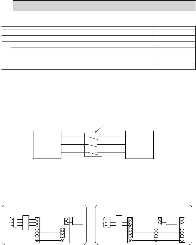
9 
 WIRING SPECIFICATIONS
9-1. FIELD ELECTRICAL WIRING (power wiring specifications)
Outdoor unit model
Outdoor unit power supply
Outdoor unit input capacity
Main switch (Breaker)
% 2) |
Outdoor unit power supply |
|
Wiring WireNo. size(mm |
Remote controller-Indoor unit |
|
|
Indoor unit-Outdoor unit |
|
|
Indoor unit-Outdoor unit earth |
|
rating |
Outdoor unit L-N (single) |
|
Outdoor unit L1-N, L2-N, L3-N (3 phase) |
||
|
||
Circuit |
Indoor unit-Outdoor unit S1-S2 |
|
Indoor unit-Outdoor unit S2-S3 |
||
|
||
|
Remote controller-Indoor unit |
|
|
|
|
HRP71V, HRP100VHA |
HRP100VHA2 |
HRP100, 125Y |
|
|
~/N (single), 50 Hz, |
~/N (single), 50 Hz, |
3N ~ (3phase), 50 Hz, |
|
*1 |
230 V |
230 V |
400 V |
|
32 A |
40 A |
16 A |
||
|
||||
*2 |
3 % Min. 4 |
3 % Min. 6 |
5 % Min. 1.5 |
|
3 % 1.5 (Polar) |
3 % 1.5 (Polar) |
3 % 1.5 (Polar) |
||
*2 |
1 % Min. 1.5 |
1 % Min. 1.5 |
1 % Min. 1.5 |
|
*3 |
2 % 0.3 (Non-polar) |
2 % 0.3 (Non-polar) |
2 % 0.3 (Non-polar) |
|
*4 |
AC 230 V |
AC 230 V |
AC 230 V |
|
*4 |
AC 230 V |
AC 230 V |
AC 230 V |
|
*4 |
DC 24 V |
DC 24 V |
DC 24 V |
|
*4 |
DC 12 V |
DC 12 V |
DC 12 V |
*1. |
A breaker with at least 3 mm contact separation in each poles shall be provided. Use earth leakage breaker(NV). |
|
The breaker shall be provided to ensure disconnection of all active phase conductor of the supply. |
*2. |
Refer to 9-3. |
*3. |
The 10 m wire is attached in the remote controller accessory. |
*4. |
The figures are NOT always against the ground. |
|
S3 terminal has DC 24 V against S2 terminal. However between S3 and S1, these terminals are NOT electrically insulated by the transformer or other device . |
Notes: 1. Wiring size must comply with the applicable local and national code.
2.Power supply cables and Indoor/Outdoor unit connecting cables shall not be lighter than polychloroprene sheathed flexible cable. (Design 60245 IEC 57)
3.Use an earth wire which is longer than other cables so that it wil not become disconnected when tension is applied.
Power supply |
|
|
|
|
|||
|
|
Isolator |
3 poles isolator |
|
|||
|
|
|
|||||
|
|
|
S1 |
|
|
S1 |
|
|
|
|
|
|
|
||
A-Control |
S2 |
|
|
S2 |
A-Control |
||
Outdoor Unit |
|
|
Indoor Unit |
||||
|
|
|
S3 |
|
|
S3 |
|
 Warning:
In case of A-control wiring,
there is high voltage potential on the S3 terminal caused by electrical circuit design that has no electrical insulation between
power line and communication signal line. Therefore, please turn off the main power supply when servicing. And do not touch the S1, S2, S3 terminals when the power is energized. If isolator should be used between indoor unit and outdoor unit, please use 3-pole type.
Turn on the main power when the ambient temperature is -20 or higher.
In below -20 condition, it needs at least 4hr standby to operate in order to warm the electrical parts.
1:1 system |
Electrical wiring |
|
|
Synchronized twin system |
Electrical wiring |
|
||||||||||
|
|
|
|
|
|
|
|
• Synchronized twin |
|
|
|
|
|
|
||
|
|
|
|
Outdoor |
Indoor |
|
|
|
|
Outdoor |
|
Indoor |
|
Indoor |
||
|
|
|
|
unit |
|
unit |
|
|
|
|
unit |
|
|
unit |
|
unit |
Unit |
|
|
|
L |
|
1 |
Remote |
Unit |
|
|
L |
|
|
1 |
Remote |
1 |
power |
|
|
|
N |
Indoor/outdoor |
2 |
controller |
power |
|
|
N |
Indoor/outdoor |
2 |
controller |
2 |
|
supply |
|
|
|
|
|
supply |
|
|
|
|
|
|
||||
|
|
|
|
|
unit connection |
|
|
|
|
|
|
unit connection |
|
|
|
|
|
|
|
|
S1 |
cable |
S1 |
|
|
|
|
S1 |
cable |
|
S1 |
|
S1 |
|
Earth leakage breaker |
|
|
Earth leakage breaker |
|
|
|
|||||||||
|
S2 |
|
S2 |
|
S2 |
|
|
S2 |
|
S2 |
||||||
|
Wiring circuit breaker or |
|
|
Wiring circuit breaker or |
|
|
|
|||||||||
|
|
isolating switch |
S3 |
|
S3 |
|
|
isolating switch |
S3 |
|
|
S3 |
|
S3 |
||
18
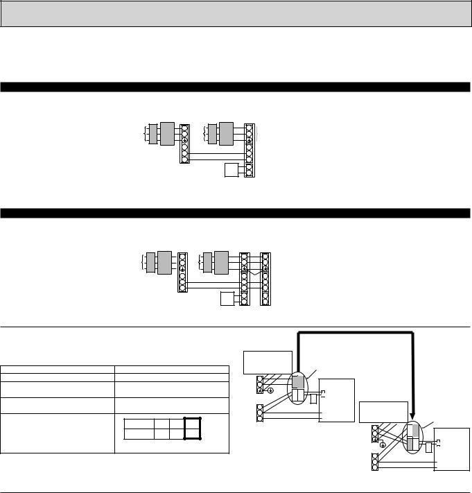
9-2. SEPARATE INDOOR UNIT/ OUTDOOR UNIT POWER SUPPLIES
The following connection patterns are available.
The outdoor unit power supply patterns vary on models.
1:1 System
<For models without heater>
*The optional indoor power supply terminal kit is required.
L |
L |
|
N |
N |
|
S1 |
S1 |
|
S2 |
S2 |
|
S3 |
S3 |
|
|
1 |
|
|
||
2 |
||
|
Outdoor unit power supplyEarth leakage breaker
Wiring circuit breaker or isolating switchOutdoor unit
Indoor unit/outdoor unit connecting cordsRemote controller
Indoor unitOption
Indoor unit power supply
* Affix a label B that is included with the manuals near each wiring diagram for the indoor and outdoor units.
Simultaneous twin system
<For models without heater>
* The optional indoor power supply terminal kits are required.
|
|
|
|
|
L |
|
L |
|
L |
N |
|
N |
|
N |
S1 |
|
S1 |
|
S1 |
S2 |
|
S2 |
|
S2 |
S3 |
|
S3 |
|
S3 |
|
|
1 |
|
1 |
|
|
|
||
|
2 |
|
2 |
|
|
|
|
Outdoor unit power supplyEarth leakage breaker
Wiring circuit breaker or isolating switchOutdoor unit
Indoor unit/outdoor unit connecting cordsRemote controller
Indoor unitOption
Indoor unit power supply
* Affix a label B that is included with the manuals near each wiring diagram for the indoor and outdoor units.
If the indoor and outdoor units have separate power supplies, refer to the table |
|
|
|
|
|
|
|
|
||||
below. If the optional indoor power supply terminal kit is used, change the indoor |
|
|
|
|
|
If the indoor and |
||||||
unit electrical box wiring referring to the figure in the right and the DIP switch |
|
Connectors ( Inisial setting: |
outdoor units have |
|||||||||
settings of the outdoor unit control board. |
|
|
|
|
Electric heater |
|
|
for indoor unit power |
separate power |
|||
|
Indoor unit specifications |
(For models with |
|
|
supplied from outdoor unit) |
supplies, change the |
||||||
|
heater) |
|
|
|
|
|||||||
|
|
|
|
|
connections of the |
|||||||
Indoor power supply terminal kit (option) |
|
Required |
|
|
|
|
|
|
||||
|
|
L |
BLUE BLUE |
|
|
|
connectors as shown |
|||||
Indoor unit electrical box connector con- |
|
Required |
|
N |
|
|
|
in the following |
||||
nection change |
|
|
|
YELLOW YELLOW |
|
ORANGE |
|
figure. |
|
|||
|
|
|
|
|
CND |
CND |
|
|
||||
Label affixed near each wiring diagram |
|
Required |
|
|
Indoor unit |
Electric heater |
|
|
|
|||
|
|
S1 |
|
|
|
|
|
|||||
for the indoor and outdoor units |
|
|
|
|
control board |
|
|
|
||||
|
|
|
|
S2 |
|
|
(For models with |
|
|
|
||
Outdoor unit DIP switch settings (when |
|
|
|
|
|
|
|
|
|
|
||
ON |
|
3 |
|
S3 |
|
|
|
heater) |
|
|
Connectors |
|
using separate indoor unit/outdoor unit |
|
|
Indoor unit power supplied from outdoor unit |
|
BLUE YELLOW |
|
||||||
1 |
(SW8) |
L |
|
|
||||||||
power supplies only) |
OFF |
2 |
(when shipped from factory) |
|
|
N |
CND |
|
||||
|
Set the SW8-3 to ON. |
|
|
|
|
|
|
YELLOW BLUE |
ORANGE |
|||
|
|
|
|
|
|
|
|
|
CND |
|||
* There are three types of labels (labels A, B, and C). Affix the appropriate labels to |
|
|
|
S1 |
|
|
Indoor unit |
|||||
|
|
|
|
|
control board |
|||||||
|
|
|
S2 |
|
|
|||||||
the units according to the wiring method. |
|
|
|
|
|
|
|
|
|
|
||
|
|
|
|
|
|
|
S3 |
|
|
|
||
|
|
|
|
|
|
|
|
|
Separate indoor unit/outdoor unit power |
|||
|
|
|
|
|
|
|
|
|
supplies |
|
|
|
Indoor unit model |
|
RP35~125 |
||
Indoor unit power supply |
|
~/N (single), 50 Hz, 230 V |
||
Indoor unit input capacity |
*1 |
16 A |
||
Main switch (Breaker) |
||||
|
|
|||
Wiring Wire No. % size (mm2) |
Indoor unit power supply |
|
2 %Min. 1.5 |
|
Indoor unit power supply earth |
|
1 %Min. 1.5 |
||
Indoor unit-Outdoor unit |
*2 |
2 %Min. 0.3 |
||
Indoor unit-Outdoor unit earth |
|
– |
||
Remote controller-Indoor unit |
*3 |
2 % 0.3 (Non-polar) |
||
|
||||
Circuit rating |
Indoor unit L-N |
*4 |
AC 230 V |
|
Indoor unit-Outdoor unit S1-S2 |
*4 |
– |
||
Indoor unit-Outdoor unit S2-S3 |
*4 |
DC24 V |
||
|
Remote controller-Indoor unit |
*4 |
DC12 V |
|
*1. A breaker with at least 3 mm contact separation in each pole shall be provided. Use earth leakage breaker (NV). The breaker shall be provided to ensure disconnection of all active phase conductor of the supply.
*2. Max. 120 m
*3.The 10 m wire is attached in the remote controller accessory. Max. 500 m *4.The figures are NOT always against the ground.
Notes: 1. Wiring size must comply with the applicable local and national code.
2.Power supply cables and indoor unit/outdoor unit connecting cables shall not be lighter than polychloroprene sheathed flexible cable. (Design 60245 IEC 57)
3.Install an earth longer than other cables.
19

9-3. INDOOR – OUTDOOR CONNECTING CABLE
The cable shall not be lighter than design 60245 IEC or 60227 IEC.
Outdoor power supply |
|
Wire No. % Size ($) |
||
|
|
|
||
Max. 45m |
Max. 50m |
Max. 80m |
||
|
||||
|
|
|
|
|
Indoor unit-Outdoor unit |
3 % 1.5 (polar) |
3 % 2.5 (polar) |
3 % 2.5 (polar) and S3 separated |
|
|
|
|
|
|
Indoor unit-Outdoor unit earth |
1 % Min. 1.5 |
1 % Min. 2.5 |
1 % Min. 2.5 |
|
|
|
|
|
|
+ The max. cable length may vary depending on the condition of installation, humidity or materials, etc. |
||||
|
|
|
||
Indoor/Outdoor separate |
|
Wire No. % Size ($) |
||
power supply |
|
|
|
|
|
Max. 120m |
|||
|
|
|||
|
|
|
||
Indoor unit-Outdoor unit |
|
2 % Min. 0.3 |
||
|
|
|
|
|
Indoor unit-Outdoor unit earth |
|
|
— |
|
|
|
|
|
|
+ The optional indoor power supply terminal kit is necessary.
Be sure to connect the indoor-outdoor connecting cables directly to the units (no intermediate connections). Intermediate connections can lead to communication errors if water enters the cables and causes insufficient insulation to ground or a poor electrical contact at the intermediate connection point.
20
9-4. M-NET WIRING METHOD
(Points to notice)
(1)Outside the unit, transmission wires should stay away from electric wires in order to prevent electromagnetic noise from making an influence on the signal communication. Place them at intervals of more than 5cm. Do not put them in the same conduit tube.
(2)Terminal block (TB7) for transmission wires should never be connected to 220~240V power supply. If it is connected, electronic parts on M-NET P.C. board may burn out.
(3)Use 2-core x 1.25mm2 shield wire (CVVS, CPEVS) for the transmission wire. Transmission signals may not be sent or received normally if different types of transmission wires are put together in the same multi-conductor cable. Never do this because this may cause a malfunction.
Group |
Refrigerant |
Refrigerant |
Refrigerant |
|
address 00 |
address 00 |
address 00 |
||
remote |
||||
M-NET |
M-NET |
M-NET |
||
controller |
||||
Power |
address 01 |
address 02 |
address 03 |
|
supply |
|
|
|
|
unit for |
|
|
|
|
transmission |
|
|
|
|
wire |
|
|
|
|
|
A-control |
A-control |
A-control |
|
|
remote |
remote |
remote |
|
|
controller |
controller |
controller |
It would be ok if M-NET wire (non-polar, 2-cores) is arranged in addition to the wiring for A-control.
(4)Ground only one of any appliances through M-NET transmission wire (shield wire). Communication error may occur due to the influence of electromagnetic noise.
“Ed” error will appear on the LED display of outdoor unit. “0403” error will appear on the central-control remote controller.
Bad example (Multi spot grounding of shield wire)
|
Central |
|
Power |
|
M-NET type |
|
M-NET type |
|
M-NET type |
|
|
remote |
|
supply |
|
|
|
|
|||
|
|
|
outdoor unit |
|
outdoor unit |
|
outdoor unit |
|
||
|
controller |
|
appliance |
|
|
|
|
|||
|
|
|
|
|
|
|
|
|
||
M-NET transmission wire |
|
|
|
|
|
|
|
|||
|
|
|
|
|||||||
|
Good example 1 (Single spot grounding of shield wire) |
|
|
|||||||
|
|
|
|
|
|
|
|
|
|
|
|
Central |
|
Power |
|
M-NET type |
|
M-NET type |
|
M-NET type |
|
|
remote |
|
supply |
|
|
|
|
|||
|
|
|
outdoor unit |
|
outdoor unit |
|
outdoor unit |
|
||
|
controller |
|
appliance |
|
|
|
|
|||
|
|
|
|
|
|
|
|
|
||
M-NET transmission wire
 Good example 2 (Single spot grounding of shield wire)
Central |
|
Power |
|
M-NET type |
|
M-NET type |
remote |
|
supply |
|
|
||
|
|
outdoor unit |
|
outdoor unit |
||
controller |
|
appliance |
|
|
||
|
|
|
|
|
M-NET type outdoor unit
M-NET transmission wire
If there are more than 2 grounding spots on the shield wire, noise may enter into the shield wire because the ground wire and shield wire form one circuit and the electric potential difference occurs due to the impedance difference among grounding spots. In case of single spot grounding, noise does not enter into the shield wire because the ground wire and shield wire do not form one circuit.
To avoid communication errors caused by noise, make sure to observe the single spot grounding method described in the installation manual.
21
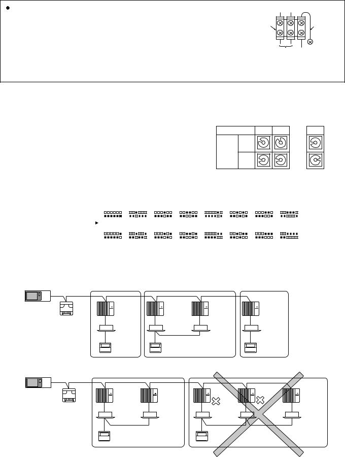
|
|
|
|
|
|
M-NET wiring |
M-NET |
|
|
||
(1) |
Use 2-core x 1.25mm2 shield wire for electric wires. |
|
|
||
|
|
||||
|
(Excluding the case connecting to system controller.) |
terminal |
|
Ground |
|
|
block |
|
|||
(2) |
Connect the wire to the M-NET terminal block. Connect one core of the |
|
wire |
||
|
|
||||
|
|
|
|||
|
transmission wire (non-polar) to A(M1) terminal and the other to B(M2). Peel the |
|
|
|
|
|
A B |
S |
|||
|
shield wire, twist the shield part to a string and connect it to S terminal. |
||||
|
Transmission |
Shield |
|||
(3) |
In the system which several outdoor units are being connected, the terminal |
||||
wire |
part |
||||
|
(A(M1), B(M2), S) on M-NET terminal block should be individually wired to the other |
||||
|
|
|
|
||
outdoor unit’s terminal, i.e. A(M1) to A(M1), B(M2) to B(M2) and S to S. In this case, choose one of those outdoor units and drive a screw to fix an ground wire on the plate as shown on the right figure.
9-4-1. M-NET address setting
In A-control models, M-NET address and refrigerant address should be set only for the outdoor unit. Similar to CITY MULTI system, there is no need to set the address of outdoor unit and remote controller. To construct a central control system, the setting of M-NET address should be conducted only upon the outdoor unit. The setting range should be 1 to 50 (the same as that of the indoor unit in CITY MULTI system), and the address number should be consecutively set in a same group.
Address number can be set by using rotary switches (SW11 for ones digit and SW12 for tens digit), which is located on the M-NET board of outdoor unit.
(Initial setting: all addresses are set to “0”.)
9-4-2. Refrigerant address setting
<Setting example> M-NET Address No.
SW11
ones
Switch digit setting SW12
tens digit
1
234 |
||
01 |
5 |
|
9 |
7 |
6 |
8 |
|
|
|
|
|
234 |
||
01 |
5 |
|
9 |
7 |
6 |
8 |
|
|
|
|
|
2
234 |
||
01 |
5 |
|
9 |
7 |
6 |
8 |
|
|
|
|
|
234 |
||
01 |
5 |
|
9 |
7 |
6 |
8 |
|
|
|
|
|
~
50
234 |
||
01 |
5 |
|
9 |
7 |
6 |
8 |
|
|
234 |
||
01 |
5 |
|
9 |
7 |
6 |
8 |
|
|
|
|
|
In case of multiple grouping system (multiple refrigerant circuits in one group), indoor units should be connected by remote controller wiring (TB5) and the refrigerant address needs to be set. Leave the refrigerant addresses to “00” if the group setting is not conducted. Set the refrigerant address by using DIP SW1-3 to -6 on the outdoor controller board. [Initial setting: all switches are OFF. (All refrigerant addresses are “00”.)]
|
|
|
ON |
|
|
|
|
|
|
|
ON |
|
|
|
|
|
|
|
ON |
|
|
|
|
|
|
|
ON |
|
|
|
|
|
|
|
ON |
|
|
|
|
|
|
|
ON |
|
|
|
|
|
|
|
ON |
|
|
|
|
|
|
|
ON |
|
|
|
|
|
|
|
|
|
|
|
|
|
|
|
|
|
|
|
|
|
|
|
|
|
|
|
|
|
|
|
|
|
|
|
|
|
|
|
|
|
|
|
|
|
|
|
|
|
|
|
|
|
|
|
|
|
|
|
|
|
|
|
|
|
|
||||||||
|
|
|
OFF |
|
|
|
|
|
|
|
OFF |
|
|
|
|
|
|
|
OFF |
|
|
|
|
|
|
|
OFF |
|
|
|
|
|
|
|
OFF |
|
|
|
|
|
|
|
OFF |
|
|
|
|
|
|
|
OFF |
|
|
|
|
|
|
|
OFF |
|
|
|
|
|
|
|
|
|
|
|
|
|
|
|
|
|
|
|
|
|
|
|
|
|
|
|
|
|
|
|
|
|
|
|
|
|
|
|
|
|
|
|
|
|
|
|
|
|
|
|
|
|
|
|
|
|
|
|
|
|
|
|
|
|
|
|
|
|
|
|
|
|
|
Refrigerant |
|
|
|
1 |
2 |
3 |
4 |
5 |
6 |
|
1 |
2 |
3 |
4 |
5 |
6 |
1 |
2 |
3 |
4 |
5 |
6 |
1 |
2 |
3 |
4 |
5 |
6 |
1 |
2 |
3 |
4 |
5 |
6 |
1 |
2 |
3 |
4 |
5 |
6 |
1 |
2 |
3 |
4 |
5 |
6 |
1 |
2 |
3 |
4 |
5 |
6 |
||||||||||||||
|
|
|
|
|
0 |
|
|
|
|
|
|
|
1 |
|
|
|
|
|
|
|
2 |
|
|
|
|
|
|
|
3 |
|
|
|
|
|
|
|
4 |
|
|
|
|
|
|
|
5 |
|
|
|
|
|
|
|
6 |
|
|
|
|
|
|
|
7 |
|
|
|
|
|
|
|
|
|
|
|
|
|
|
|
|
|
|
|
|
|
|
|
|
|
|
|
|
|
|
|
|
|
|
|
|
|
|
|
|
|
|
|
|
|
|
|
|
|
|
|
|
|
|
|
|
|
|
|
|
|
|
||||||||||
address |
|
|
|
|
|
|
|
|
|
|
|
|
|
|
|
|
|
|
|
|
|
|
|
|
|
|
|
|
|
|
|
|
|
|
|
|
|
|
|
|
|
|
|
|
|
|
|
|
|
|
|
|
|
|
|
|
|
|
|
|
|
|
|
|
||
ON |
|
|
|
|
|
|
|
ON |
|
|
|
|
|
|
|
ON |
|
|
|
|
|
|
|
ON |
|
|
|
|
|
|
|
ON |
|
|
|
|
|
|
|
ON |
|
|
|
|
|
|
|
ON |
|
|
|
|
|
|
|
ON |
|
|
|
|
|
|
|
|||
|
|
|
OFF |
|
|
|
|
|
|
|
OFF |
|
|
|
|
|
|
|
OFF |
|
|
|
|
|
|
|
OFF |
|
|
|
|
|
|
|
OFF |
|
|
|
|
|
|
|
OFF |
|
|
|
|
|
|
|
OFF |
|
|
|
|
|
|
|
OFF |
|
|
|
|
|
|
|
|
|
|
|
|
|
|
|
|
|
|
|
|
|
|
|
|
|
|
|
|
|
|
|
|
|
|
|
|
|
|
|
|
|
|
|
|
|
|
|
|
|
|
|
|
|
|
|
|
|
|
|
|
|
|
|
|
|
|
|
|
|
|
|
|
|
|
|
|
|
|
1 |
2 |
3 |
4 |
5 |
6 |
|
1 |
2 |
3 |
4 |
5 |
6 |
|
1 |
2 |
3 |
4 |
5 |
6 |
|
1 |
2 |
3 |
4 |
5 |
6 |
|
1 |
2 |
3 |
4 |
5 |
6 |
|
1 |
2 |
3 |
4 |
5 |
6 |
|
1 |
2 |
3 |
4 |
5 |
6 |
|
1 |
2 |
3 |
4 |
5 |
6 |
|
|||||||
|
|
|
|
|
|
8 |
|
|
|
|
|
|
|
9 |
|
|
|
|
|
|
|
10 |
|
|
|
|
|
|
11 |
|
|
|
|
|
|
|
12 |
|
|
|
|
|
|
13 |
|
|
|
|
|
|
14 |
|
|
|
|
|
|
15 |
|
|
|
|||||
9-4-3. Regulations in address settings
In case of multiple grouping system, M-NET and refrigerant address settings should be done as explained in the above section. Set the lowest number in the group for the outdoor unit whose refrigerant address is “00” as its M-NET address.
|
Group A |
Group B |
|
Group C |
System |
Refrigerant |
Refrigerant |
Refrigerant |
Refrigerant |
address 00 |
address 00 |
address 01 |
address 00 |
|
controller |
M-NET |
M-NET |
M-NET |
M-NET |
Power |
address 01 |
address 02 |
address 03 |
address 04 |
supply |
|
|
|
|
unit for |
|
|
|
|
transmission |
|
|
TB5 |
|
wire |
|
|
|
|
|
A-control |
A-control |
|
A-control |
|
remote |
remote |
|
remote |
|
controller |
controller |
|
controller |
w Refrigerant addresses can be overlapped if they are in the different group.
|
Group A |
|
|
Group B |
|
|
System |
Refrigerant |
Refrigerant |
Refrigerant |
Refrigerant |
Refrigerant |
|
address 00 |
address 01 |
address 00 |
address 01 |
address 02 |
||
controller |
||||||
M-NET |
M-NET |
M-NET |
M-NET |
M-NET |
||
|
||||||
Power |
address 01 |
address 02 |
address 04 |
address 03 |
address 05 |
|
supply |
|
|
|
|
|
|
unit for |
|
|
|
|
|
|
transmission |
|
|
TB5 |
|
|
|
wire |
|
|
|
|
||
|
A-control |
|
A-control |
|
|
|
|
remote |
|
remote |
|
|
|
|
controller |
|
controller |
|
|
wIn group B, M-NET address of the outdoor unit whose refrigerant address is “00” is not set to the minimum in the group. As “3” is right for this situation, the setting is wrong. Taking group A as a good sample, set the minimum M-NET address in the group for the outdoor unit whose refrigerant address is “00”.
22
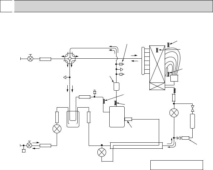
10 
 REFRIGERANT SYSTEM DIAGRAM
PUHZ-HRP71VHA |
PUHZ-HRP100VHA |
PUHZ-HRP100YHA |
|
PUHZ-HRP125YHA |
|||
PUHZ-HRP71VHA2 |
PUHZ-HRP100VHA2 |
PUHZ-HRP100YHA2 |
|
PUHZ-HRP125YHA2 |
|||
|
|
|
|
|
High pressure sensor (63HS) |
|
Thermistor TH7 |
|
|
|
|
|
(only for HRP·HA2) Heat exchanger |
(Outdoor) |
|
|
|
|
|
|
|
|
Thermistor |
|
Ball valve |
|
Solenoid valve |
|
|
|
TH6 |
|
|
(Four-way valve) |
|
|
|
(Outdoor |
|
|
|
|
|
|
|
||
Refrigerant |
|
|
|
|
|
|
2-phase pipe) |
GAS pipe |
Strainer |
|
|
|
|
|
|
connection |
|
|
|
|
|
|
|
#50 |
|
Charge plug |
|
|
|
||
(5/8 inch) |
|
|
|
Thermistor TH3 |
|||
|
|
(High pressure) |
|
|
|||
|
|
|
|
|
(Outdoor pipe) |
||
|
|
|
|
|
|
|
|
|
Charge plug |
Muffler |
High pressure |
|
Distributor |
||
|
(Low pressure) |
|
|
|
|||
|
|
|
Low pressure |
|
switch 63H |
|
|
|
|
|
|
|
|
|
|
|
|
|
switch 63L |
|
Thermistor |
|
Thermistor TH33 |
|
|
|
|
|
|
||
|
|
|
|
|
|
(Outdoor pipe) |
|
|
|
|
|
|
TH32 |
|
|
|
|
|
|
|
|
|
|
|
|
|
|
|
(Outdoor pipe) |
Strainer |
|
|
|
|
Strainer |
|
Thermistor TH4 |
#100 |
|
|
|
|
#100 |
|
|
|
|
|
|
|
|
|
(Discharge) |
|
Bypass |
|
|
|
|
|
|
|
|
valve
|
|
|
Strainer |
Strainer |
|
Linear expansion valve A |
|
|
|
|
#100 |
#100 |
|
|
Replace |
|
|
Linear |
|
|
|
|
|
|
|
|
|
|
Injection port |
filter |
|
|
|
expansion valve B |
Power |
Compressor |
|
||
|
|
|
|
|
|
||
|
|
|
|
receiver |
|
|
|
Refrigerant |
|
|
|
|
|
Restrictor |
Strainer |
LIQUID pipe |
|
Strainer |
Linear |
|
valve |
#100 |
|
connection |
|
|
Heat interchange circuit |
||||
(3/8 inch) |
Stop valve |
#100 |
expansion valve C |
|
|||
|
(with service port) |
|
|
|
|
||
 Refrigerant flow in cooling
 Refrigerant flow in heating
23

10-1. Refrigerant recovering (pump down)
Perform the following procedures to recover the refrigerant when moving the indoor unit or the outdoor unit. 1Turn on the power supply (circuit breaker).
wWhen power is supplied, make sure that “CENTRALLY CONTROLLED” is not displayed on the remote controller. If “CENTRALLY CONTROLLED” is displayed, the refrigerant recovering (pump down) cannot be completed normally.
2After the liquid stop valve is closed, set the SWP switch on the control board of the outdoor unit to ON. The compressor (outdoor unit) and fans (indoor and outdoor units) start operating and refrigerant recovering operation begins. LED1 and LED2 on the control board of the outdoor unit are lit.
wSet the SWP switch (push-button type) to ON in order to perform refrigerant recovering operation only when the unit is stopped. However, refrigerant recovering operation cannot be performed until compressor stops even if the unit is stopped. Wait 3 minutes until compressor stops and set the SWP switch to ON again.
3Because the unit automatically stops in about 2 to 3 minutes after the refrigerant recovering operation (LED1 is not lit and LED2 is lit), be sure to quickly close the gas stop valve.
wIn case the outdoor unit is stopped when LED1 is lit and LED2 is not lit, open the liquid stop valve completely, and then repeat step 2 3 minutes later.
wIf the refrigerant collecting operation has been completed normally (LED1 is not lit and LED2 is lit), the unit will remain stopped until the power supply is turned off.
4Turn off the power supply (circuit breaker).
10-2. Unit replacement operation
When reusing the existing pipes that carried R22 refrigerant for the HRP71, HRP100 and HRP125 models, replacement operation must be performed before performing a test run.
1If new pipes are used, these procedures are not necessary.
2During replacement operation, “C5” is displayed on “A-Control Service Tool(PAC-SK52ST)”.
Replacement operation procedures
1Turn on the power supply.
2Set DIP switch SW8-2 on the control board of the outdoor unit to ON to start replacement operation.
•The replacement operation is performed using the cooling system. Cool air will flow from the indoor unit during the replacement operation.
•During the replacement operation, TEST RUN is displayed on the remote controller and LED1 (green) and LED2 (red) on the control board of the outdoor unit blink together.
3Replacement operation requires at least 2 hours to complete.
•After setting switch SW8-2 to ON, the unit automatically stops after 2 hours.
•Replacement operation can be performed repeatedly by setting switch SW8-2 from OFF to ON. Make sure to perform the operation more than 2 hours. (If the operation is performed less than 2 hours, the existing pipes cannot be cleaned enough and the unit may be damaged.)
•If replacement operation is performed over 2 hours, this action is recorded into nonvolatile memory of control board. 4Set switch SW8-2 to OFF. (Replacement operation is completed.)
wThe unit can be operated normally by remote controller even if SW8-2 remains ON.
wIf the indoor temperature is less than 15:, the compressor will operate intermittently but the unit is not faulty.
10-3. Start and finish of test run
•Operation from the indoor unit
Execute the test run using the installation manual for the indoor unit.
•Operation from the outdoor unit
By using the DIP switch SW4 on the control board of outdoor unit, test run can be started and finished, and its operation mode (cooling/heating) can be set up.
1Set the operation mode (cooling/heating) using SW4-2.
2Turn on SW4-1 to start test run with the operation mode set by SW4-2. 3Turn off SW4-1 to finish the test run.
•There may be a faint knocking sound around the machine room after power is supplied, but this is no problem with product because the linear expansion pipe is just moving to adjust opening pulse.
•There may be a knocking sound around the machine room for several seconds after compressor starts operating, but this is no problem with product because the check valve itself generates the sound because pressure difference is small in the refrigerant circuit.
<SW4>
ON OFF
1 2
Stop OperationCooling Heating
Note:
The operation mode cannot be changed by SW4-2 during test run. (To change test run mode, stop the unit by SW4-1, change the operation mode and restart the test run by SW4-1.)
24

11 
 TROUBLESHOOTING
11-1. TROUBLESHOOTING
<Error code display by self-diagnosis and actions to be taken for service (summary)>
Present and past error codes are logged and displayed on the wired remote controller and control board of outdoor unit. Actions to be taken for service, which depends on whether or not the trouble is reoccurring at service, are summarized in the table below. Check the contents below before investigating details.
Unit conditions at service |
Error code |
Actions to be taken for service (summary) |
|
|
|
|
Displayed |
Judge what is wrong and take a corrective action according |
|
to “11-4. Self-diagnosis action table”. |
|
The trouble is reoccurring. |
|
|
|
|
|
|
Not displayed |
Conduct troubleshooting and ascertain the cause of the |
|
trouble according to “11-5. Troubleshooting by inferior |
|
|
|
phenomena”. |
|
|
|
|
|
Consider the temporary defects such as the work of |
|
|
protection devices in the refrigerant circuit including |
|
|
compressor, poor connection of wiring, noise and etc. |
|
|
Re-check the symptom, and check the installation |
|
|
environment, refrigerant amount, weather when the |
|
Logged |
trouble occurred, matters related to wiring and etc. |
|
Reset error code logs and restart the unit after finishing |
|
|
|
|
|
|
service. |
|
|
There is no abnormality in electrical component, |
|
|
controller board, remote controller and etc. |
The trouble is not reoccurring. |
|
|
|
|
Re-check the abnormal symptom. |
|
|
Conduct trouble shooting and ascertain the cause of the |
|
|
trouble according to “11-5. Troubleshooting by inferior |
|
Not logged |
phenomena”. |
|
Continue to operate unit for the time being if the cause |
|
|
|
is not ascertained. |
|
|
There is no abnormality concerning of parts such as |
|
|
electrical component, controller board, remote controller |
|
|
and etc. |
|
|
|
11-2. CHECK POINT UNDER TEST RUN
(1) Before test run
•After installation of indoor and outdoor units, piping work and electric wiring work, re-check that there is no refrigerant leakage, loosened connections and incorrect polarity.
•Measure impedance between the ground and the power supply terminal block (L, N) on the outdoor unit by 500V Megger and check that it is 1.0M" or over.
wDon’t use 500V Megger to indoor/outdoor connecting wire terminal block (S1, S2, S3) and remote controller terminal block (1, 2). This may cause malfunction.
•Make sure that test run switch (SW4) is set to OFF before turning on power supply.
•Turn on power supply 12 hours before test run in order to protect compressor.
•For specific models which requires higher ceiling settings or power failure automatic recovery, make proper changes of set-
tings referring to the description of “Selection of Functions through Remote Controller”. Make sure to read operation manual before test run. (Especially items to secure safety.)
25
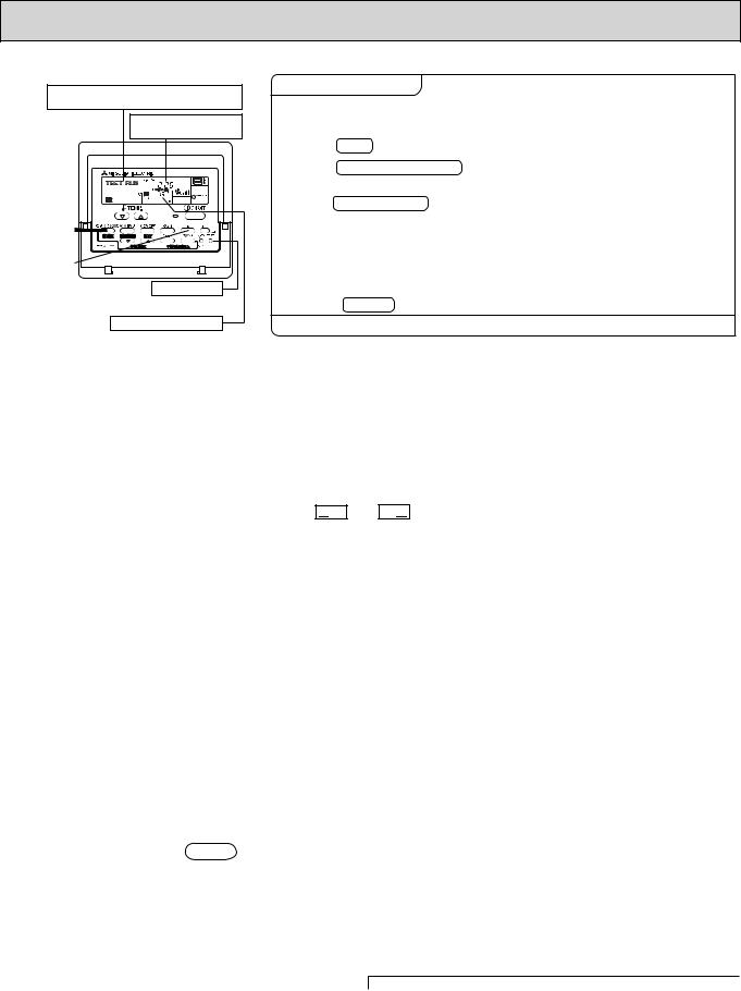
"TEST RUN" and the currently selected operation mode are displayed altemately.
Displays the remaining test run time.
|
|
[TEST] button
Pipe (liquid) temperature
Operating procedures |
While the room temperature display on the remote |
|||
|
controller is “PLEASE WAIT”, the remote controller is disabled. |
|||
1. Turn on the main power supply. |
Wait until “PLEASE WAIT” disappears before using remote controller. |
|||
“PLEASE WAIT” appears for about 2 minutes after power |
||||
|
supply is turned on. +1 |
|||
2. Press TEST button twice. |
The |
|
appears on the screen. |
|
TEST RUN |
||||
|
||||
|
|
|
|
|
3. Press OPERATION SWITCH |
Cooling mode: Check if cool air blows and water is drained. |
|||
Heating mode: Check if warm air blows. (It takes a little |
||||
button. |
||||
|
while until warm air blows.) |
|||
4. Press AIR DIRECTION button. |
Check for correct motion of auto-vanes. |
|||
|
|
|
|
|
5. Check the outdoor unit fan for |
The outdoor unit features automatic capacity control to |
|||
correct running. |
provide optimum fan speeds. Therefore, the fan keeps |
|||
running at a low speed to meet the current outside air |
||||
|
||||
|
condition unless it exceeds its available maximum power. |
|||
|
Then, in actuality, the fan may stop or run in the reverse |
|||
|
direction depending on the outside air, but this does not |
|||
|
mean malfunction. |
|||
6.Press the ON/OFF button to reset the test run in progress.
7.Register the contact number.
•In case of test run, the OFF timer will be activated, and the test run will automatically stop after 2 hours.
•The room temperature display section shows the pipe temperature of indoor units during the test run.
•Check that all the indoor units are running properly in case of simultaneous twin operation. Malfunctions may not be displayed regardless of incorrect wiring.
w1 After turning on the power supply, the system will go into startup mode, “PLEASE WAIT” will blink on the display section of the room temperature, and lamp(green) of the remote controller will flash.
As to INDOOR BOARD LED, LED1 will be lit up, LED2 will either be lit up in case the address is 0 or turned off in case the address is not 0. LED3 will blink.
As to OUTDOOR BOARD LED, LED1(green) and LED2(red) will be lit up. (After the startup mode of the system finishes, LED2(red) will be turned off.)
In case OUTDOOR BOARD LED is digital display,  — and —
  will be displayed alternately every second.
•If one of the above operations doesn’t function correctly, the causes written below should be considered. Find causes from the symptoms.
The below symptoms are under test run mode. “startup” in the table means the display status of w1 written above.
Symptoms in test run mode |
Cause |
|||
Remote Controller Display |
OUTDOOR BOARD LED Display |
|||
< > indicates digital display. |
|
|
||
Remote controller displays “PLEASE |
After “startup” is displayed, only |
• After power is turned on, “PLEASE WAIT” is displayed for 2 |
|
|
WAIT”, and cannot be operated. |
green lights up. <00> |
minutes during system startup. (Normal) |
||
|
After “startup” is displayed, |
• Incorrect connection of outdoor terminal block (L1, L2, L3 and |
||
|
green(once) and red(once) blink |
|||
After power is turned on, “PLEASE WAIT” |
alternately. <F1> |
S1, S2, S3.) |
||
is displayed for 3 minutes, then error code |
|
|
|
|
After “startup” is displayed, |
|
|
||
is displayed. |
green(once) and red(twice) blink |
• Outdoor unit’s protection device connector is open. |
||
|
alternately. <F3, F5, F9> |
|
|
|
|
After “startup” is displayed, |
• Incorrect wiring between the indoor and outdoor unit (Polarity |
||
No display appears even when remote |
green(twice) and red(once) blink |
is wrong for S1, S2, S3.) |
||
alternately. <EA. Eb> |
• Remote controller transmission wire is short. |
|||
controller operation switch is turned on. |
||||
After “startup” is displayed, only |
• There is no outdoor unit of address 0. |
|||
(Operation lamp does not light up.) |
||||
(Address is other than 0.) |
||||
|
green lights up. <00> |
|||
|
• Remote controller transmission wire is open. |
|||
|
|
|||
Display appears but soon disappears |
After “startup” is displayed, only |
• After canceling function selection, operation is not possible for |
||
even when remote controller is operated. |
green lights up. <00> |
about 30 seconds. (Normal) |
||
w Press the remote controller’s CHECK button twice to perform self-diagnosis. See the table below for the contents of LCD display.
LCD |
Contents of inferior phenomena |
LCD |
|
Contents of inferior phenomena |
P1 |
Abnormality of room temperature thermistor |
U1~UP |
Malfunction outdoor unit |
|
P2 |
Abnormality of pipe temperature thermistor/Liquid |
F3~F9 |
Malfunction outdoor unit |
|
P4 |
Abnormality of drain sensor/ Float switch connector open |
E0~E5 |
Remote controller transmitting error |
|
P5 |
Drain overflow protection is working. |
E6~EF |
Indoor/outdoor unit communication error |
|
P6 |
Freezing/overheating protection is working. |
---- |
No |
error history |
P8 |
Abnormality of pipe temperature |
FFFF |
No applied unit |
|
P9 |
Abnormality of pipe temperature thermistor/Cond./Eva |
PA |
Forced compressor stop(due to water leakage abnormality) |
|
Fb |
Abnormality of indoor controller board |
|
|
|
See the table below for details of the LED display (LED 1, 2, 3) on the indoor controller board.
LED1 (microcomputer power supply) |
Lits when power is supplied. |
|
LED2 (remote controller) |
Lits when power is supplied for wired remote controller. |
|
The indoor unit should be connected to the outdoor unit with address “0” setting. |
||
|
||
LED3 (indoor/outdoor communication) |
Blinks when indoor and outdoor unit are communicating. |
|
|
|
26
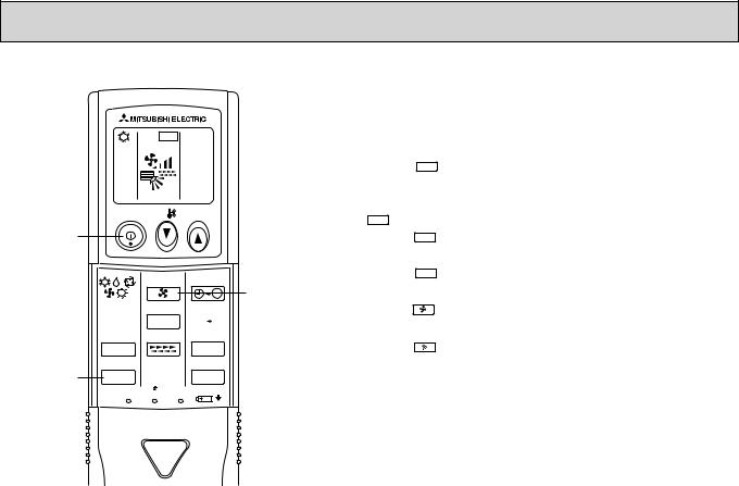
TEST RUN
ON/OFF |
TEMP |
|
|
FAN |
AUTO STOP |
|
|
MODE VANE |
AUTO START |
, 


CHECK LOUVER h
TEST RUN |
min |
|
|
SET |
RESET CLOCK |
Test run [for wireless remote controller]
Measure an impedance between the power supply terminal block on the outdoor unit and ground with a 500V Megger and check that it is equal to or greater than 1.0M".
1 Turn on the main power to the unit.
2Press the TEST RUN button twice continuously.
(Start this operation from the status of remote controller display turned off.)
A TEST RUN and current operation mode are displayed.
3Press the MODE ( 


 ) button to activate COOL
 mode, then check whether cool air is blown out from the unit.
4Press the MODE ( 


 ) button to activate HEAT
  mode, then check whether warm air is blown out from the unit.
5 Press the FAN button and check whether strong air is blown out from the unit.
6Press the VANE button and check whether the auto vane operates properly.
7 Press the ON/OFF button to stop the test run.
Note:
•Point the remote controller towards the indoor unit receiver while following steps 2 to 7.
•It is not possible to run in FAN, DRY or AUTO mode.
27
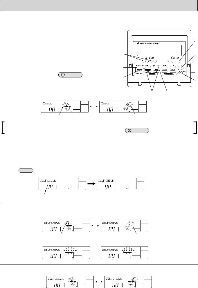
11-3. HOW TO PROCEED “SELF-DIAGNOSIS”
11-3-1. When a Problem Occurs During Operation
If a problem occurs in the air conditioner, the indoor and outdoor units will stop, and the problem is shown in the remote controller display.
[CHECK] and the refrigerant address are displayed on the temperature display, and the error code and unit number are
displayed alternately as shown below. (If the outdoor unit is malfunctioning, the unit number will be “00”.)
In the case of group control, for which one remote controller controls multiple refrigerant systems, the refrigerant address and error code of the unit that first experienced trouble (i.e., the unit that transmitted the error code) will be displayed.
To clear the error code, press the |
ON/OFF button. |
(Alternating Display)
Error code (2 or 4 digits) |
Address (3 digits) or unit number (2 digits) |
When using remote-/local-controller combined operation, cancel the error code after turning off remote operation. During
central control by a MELANS controller, cancel the error code by pressing the |
ON/OFF button. |
11-3-2. Self-Diagnosis During Maintenance or Service
Since each unit has a function that stores error codes, the latest check code can be recalled even if it is cancelled by the remote controller or power is turned off.
Check the error code history for each unit using the remote controller.
Switch to self-diagnosis mode.
Press the CHECK button twice within 3 seconds. The display content will change as shown below.
Unit number or refrigerant address to be diagnosed
Set the unit number or refrigerant address you want to diagnose.
Press the [TEMP] buttons ( and
and  ) to select the desired number or address. The number (address) changes between [01] and [50] or [00] and [15].
The refrigerant address will begin to blink approximately 3 seconds after being
selected and the self-diagnosis process will begin.
Display self-diagnosis results. <When there is error code history>
(For the definition of each error code, refer to the indoor unit's installation manual or service handbook.)
(Alternating Display)
Error code (2 or 4 digits) <When there is no error code history>
Address (3 digits) or unit number (2 digits) <When there is no corresponding unit>
Reset the error history.
Display the error history in the diagnosis result display screen (see step ).
28
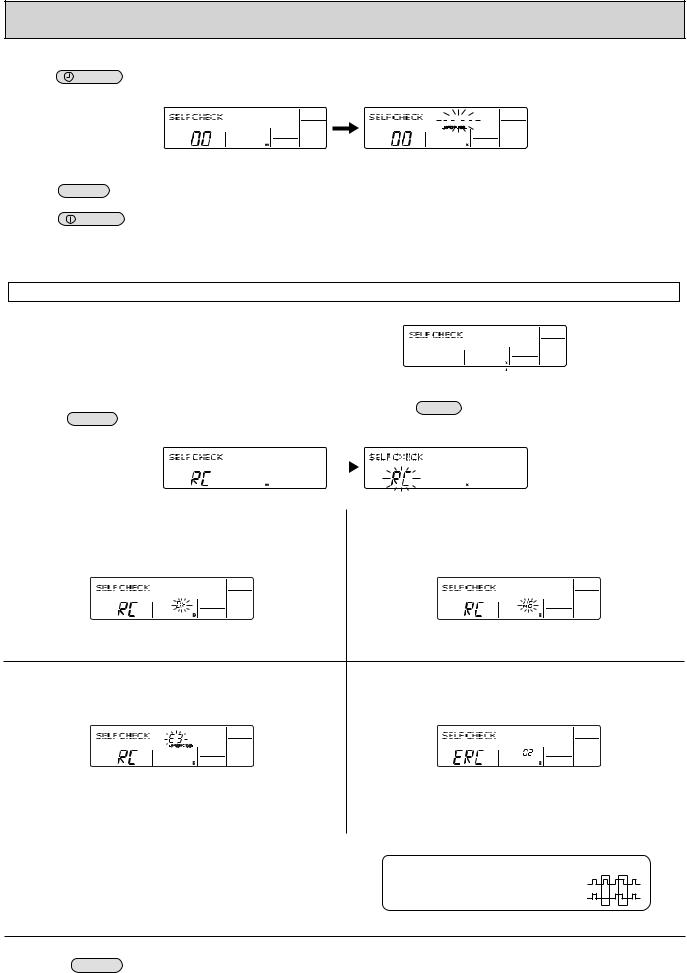
Press the |
ON/OFF button twice within 3 seconds. The self-diagnosis |
address or refrigerant address will blink.
Cancel self-diagnosis.
Self-diagnosis can be cancelled by the following 2 methods.
When the error history is reset, the display will look like the one shown below. However, if you fail to reset the error history, the error content will be displayed again.
Press the CHECK button twice within 3 seconds.
Self-diagnosis will be cancelled and the screen will return to the previous state in effect before the start of self-diagnosis.
Press the |
ON/OFF button. |
Self-diagnosis will be cancelled and the indoor unit will stop. |
11-3-3. Remote Controller Diagnosis
If the air conditioner cannot be operated from the remote controller, diagnose the remote controller as explained below.
First, check that the power-on indicator is lit.
If the correct voltage (DC12 V) is not supplied to the remote controller, the indicator will not light.
If this occurs, check the remote controller's wiring and the indoor unit.
|
|
|
|
|
|
|
|
|
|
|
|
|
|
|
|
|
|
|
|
|
|
Power on indicator |
||
|
|
|
|
|
|
|
|
|
|
|
|
|
|
|
|
|
|
|
|
|
|
|||
|
|
|
|
|
|
|
|
|
|
|
|
|
|
|
|
|
|
|
|
|
|
|
|
|
Switch to the remote controller self-diagnosis mode. |
Press the FILTER |
button to start self-diagnosis. |
||||||||||||||||||||||
Press the CHECK button for 5 seconds or more. The display content will |
||||||||||||||||||||||||
|
|
|
|
|
|
|
|
|
|
|
|
|
|
|
|
|||||||||
change as shown below. |
|
|
|
|
|
|
|
|
|
|
|
|
|
|
|
|
||||||||
|
|
|
|
|
|
|
|
|
|
|
|
|
|
|
|
|
|
|
|
|
|
|
|
|
|
|
|
|
|
|
|
|
|
|
|
|
|
|
|
|
|
|
|
|
|
|
|
|
|
|
|
|
|
|
|
|
|
|
|
|
|
|
|
|
|
|
|
|
|
|
|
|
|
|
|
|
|
|
|
|
|
|
|
|
|
|
|
|
|
|
|
|
|
|
|
|
|
|
|
|
|
|
|
|
|
|
|
|
|
|
|
|
|
|
|
|
|
|
|
|
|
|
|
|
|
|
|
|
|
|
|
|
|
|
|
|
|
|
|
|
|
|
|
|
|
|
|
|
|
Remote controller self-diagnosis result
[When the remote controller is functioning correctly]
Check for other possible causes, as there is no problem with the remote controller.
[Where the remote controller is not defective, but cannot be operated.] (Error display 2) [E3], [6833] or [6832] blinks.© Transmission is not possible.
There might be noise or interference on the transmission path, or the indoor unit or other remote controllers are defective. Check the transmission path and other controllers.
[When the remote controller malfunctions]
(Error display 1) "NG" blinks. ©©The remote controller's transmitting-receiv- ing circuit is defective.
The remote controller must be replaced with a new one.
(Error display 3) "ERC" and the number of data errors are displayed. © Data error has occurred.
The number of data errors is the difference between the number of bits sent from the remote controller and the number actually transmitted through the transmission path. If such a problem is occurring, the transmitted data is affected by noise, etc. Check the transmission path.
 When the number of data errors is "02":
Transmission data from remote controller
Transmission data on transmission path
To cancel remote controller diagnosis
Press the CHECK button for 5 seconds or more. Remote controller diagnosis will be cancelled, "PLEASE WAIT" and operation lamp will blink. After approximately 30 seconds, the state in effect before the diagnosis will be restored.
29
11-3-4. Malfunction-diagnosis method by wireless remote controller
<In case of trouble during operation>
When a malfunction occurs to air conditioner, both indoor unit and outdoor unit will stop and operation lamp blinks to inform unusual stop.
<Malfunction-diagnosis method at maintenance service>
|
|
|
Refrigerant |
|
|
|
address |
CHECK |
|
display |
|
|
|
||
CHECK |
|
|
|
display |
|
|
|
|
|
|
Temperature |
ON/OFF |
TEMP |
button |
|
|
|||
ON/OFF |
|
|
|
button |
|
|
|
|
FAN |
AUTO STOP |
|
MODE |
VANE |
AUTO START |
HOUR |
|
|
|
|
CHECK |
LOUVER |
h |
button |
|
|||
CHECK TEST RUN |
|
min |
|
button |
|
|
|
SET |
RESET CLOCK |
|
|
[Procedure]
1.Press the CHECK button twice.
2.Press the temperature 
 buttons.
3.Point the remote controller at the sensor on the indoor unit and press the HOUR button.
4.Point the remote controller at the sensor on the indoor unit and press the ON/OFF button.
•"CHECK" lights, and refrigerant address "00" blinks.
•Check that the remote controller's display has stopped before continuing.
•Select the refrigerant address of the indoor unit for the self-diagnosis.
Note: Set refrigerant address using the outdoor unit’s DIP switch (SW1). (For more information, see the outdoor unit installation manual.)
•If an air conditioner error occurs, the indoor unit's sensor emits an intermittent buzzer sound, the operation lamp blinks, and the error code is output.
(It takes 3 seconds at most for error code to appear.)
•The check mode is cancelled.
30
 Loading...