


Q64TCRTBWN
Table of contents
 Loading...
MELSEC-Q Temperature Control Module
User's Manual
-Q64TCTTN
-Q64TCTTBWN
-Q64TCRTN
-Q64TCRTBWN

SAFETY PRECAUTIONS
(Read these precautions before using this product.)
Before using this product, please read this manual and the relevant manuals carefully and pay full attention
to safety to handle the product correctly.
The precautions given in this manual are concerned with this product only. For the safety precautions of the
programmable controller system, refer to the user's manual for the CPU module used.
In this manual, the safety precautions are classified into two levels: " CAUTION" and " WARNING".
WARNING
CAUTION
Under some circumstances, failure to observe the precautions given under " CAUTION" may lead to
serious consequences.
Observe the precautions of both levels because they are important for personal and system safety.
Make sure that the end users read this manual and then keep the manual in a safe place for future
reference.
Indicates that incorrect handling may cause hazardous conditions,
resulting in death or severe injury.
Indicates that incorrect handling may cause hazardous conditions,
resulting in minor or moderate injury or property damage.
[Design Precautions]
WARNING
● Outputs may remain on or off due to a failure of a component such as a transistor in an output circuit.
Configure an external circuit for monitoring output signals that could cause a serious accident.
● Do not write any data to the "system area" and "write-protect area" (R) of the buffer memory in the
intelligent function module. Also, do not use any "use prohibited" signal as an input or output signal
from the intelligent function module to the programmable controller CPU.
Doing so may cause malfunction of the programmable controller system.
CAUTION
● Do not install the control lines or communication cables together with the main circuit lines or power
cables. Keep a distance of 100mm or more between them.
Failure to do so may result in malfunction due to noise.
1

[Installation Precautions]
CAUTION
● Use the programmable controller in an environment that meets the general specifications in the user's
manual for the CPU module used.
Failure to do so may result in electric shock, fire, malfunction, or damage to or deterioration of the
product.
● To mount the module, while pressing the module mounting lever located in the lower part of the
module, fully insert the module fixing projection(s) into the hole(s) in the base unit and press the
module until it snaps into place.
Incorrect mounting may cause malfunction, failure or drop of the module.
When using the programmable controller in an environment of frequent vibrations, fix the module with
a screw.
● Tighten the screw within the specified torque range.
Undertightening can cause drop of the screw, short circuit or malfunction.
Overtightening can damage the screw and/or module, resulting in drop, short circuit, or malfunction.
● Shut off the external power supply (all phases) used in the system before mounting or removing the
module.
Failure to do so may result in damage to the product.
A module can be replaced online (while power is on) on any MELSECNET/H remote I/O station or in
the system where a CPU module supporting the online module change function is used.
Note that there are restrictions on the modules that can be replaced online, and each module has its
predetermined replacement procedure.
For details, refer to the relevant chapter in this manual.
● Do not directly touch any conductive parts and electronic components of the module.
Doing so can cause malfunction or failure of the module.
2

[Wiring Precautions]
CAUTION
● Individually ground the shielded cables of the programmable controller with a ground resistance of
100 or less.
Failure to do so may result in electric shock or malfunction.
● Use applicable solderless terminals and tighten them within the specified torque range.
If any spade solderless terminal is used, it may be disconnected when the terminal screw comes
loose, resulting in failure.
● Check the rated voltage and terminal layout before wiring to the module, and connect the cables
correctly.
Connecting a power supply with a different voltage rating or incorrect wiring may cause a fire or
failure.
● Prevent foreign matter such as dust or wire chips from entering the module.
Such foreign matter can cause a fire, failure, or malfunction.
● A protective film is attached to the top of the module to prevent foreign matter, such as wire chips,
from entering the module during wiring.
Do not remove the film during wiring.
Remove it for heat dissipation before system operation.
● Place the cables in a duct or clamp them. If not, dangling cable may swing or inadvertently be pulled,
resulting in damage to the module or cables or malfunction due to poor contact.
● When disconnecting the cable from the module, do not pull the cable by the cable part.
For the cable connected to the terminal block, loosen the terminal screw.
Pulling the cable connected to the module may result in malfunction or damage to the module or
cable.
3

[Startup and Maintenance Precautions]
CAUTION
● Do not touch any terminal while power is on.
Doing so will cause electric shock or malfunction.
● Shut off the external power supply (all phases) used in the system before cleaning the module or
retightening the terminal screws or module fixing screws.
Failure to do so may result in electric shock or cause the module to fail or malfunction.
Undertightening can cause drop of the component or wire, short circuit, or malfunction.
Overtightening can damage the screw and/or module, resulting in drop, short circuit, or malfunction.
● Do not disassemble or modify the module.
Doing so may cause failure, malfunction, injury, or a fire.
● Shut off the external power supply (all phases) used in the system before mounting or removing the
module.
Failure to do so may cause the module to fail or malfunction.
A module can be replaced online (while power is on) on any MELSECNET/H remote I/O station or in
the system where a CPU module supporting the online module change function is used.
Note that there are restrictions on the modules that can be replaced online, and each module has its
predetermined replacement procedure.
For details, refer to the relevant chapter in this manual.
● After the first use of the product, do not mount/remove the module to/from the base unit, and the
terminal block to/from the module more than 50 times (IEC 61131-2 compliant) respectively.
Exceeding the limit of 50 times may cause malfunction.
● Before handling the module, touch a grounded metal object to discharge the static electricity from the
human body.
Failure to do so may cause the module to fail or malfunction.
[Disposal Precautions]
CAUTION
● When disposing of this product, treat it as industrial waste.
4

CONDITIONS OF USE FOR THE PRODUCT
(1) Mitsubishi programmable controller ("the PRODUCT") shall be used in conditions; i) where any
problem, fault or failure occurring in the PRODUCT, if any, shall not lead to any major or serious
accident; and ii) where the backup and fail-safe function are systematically or automatically
provided outside of the PRODUCT for the case of any problem, fault or failure occurring in the
PRODUCT.
(2) MITSUBISHI SHALL HAVE NO RESPONSIBILITY OR LIABILITY (INCLUDING, BUT NOT
LIMITED TO ANY AND ALL RESPONSIBILITY OR LIABILITY BASED ON CONTRACT,
WARRANTY, TORT, PRODUCT LIABILITY) FOR ANY INJURY OR DEATH TO PERSONS OR
LOSS OR DAMAGE TO PROPERTY CAUSED BY the PRODUCT THAT ARE OPERATED OR
USED IN APPLICATION NOT INTENDED OR EXCLUDED BY INSTRUCTIONS, PRECAUTIONS,
OR WARNING CONTAINED IN MITSUBISHI'S USER, INSTRUCTION AND/OR SAFETY
MANUALS, TECHNICAL BULLETINS AND GUIDELINES FOR the PRODUCT. ("Prohibited
Application") Prohibited Applications include, but not limited to, the use of the PRODUCT in;
• Nuclear Power Plants and any other power plants operated by Power companies, and/or any
other cases in which the public could be affected if any problem or fault occurs in the PRODUCT.
• Railway companies or Public service purposes, and/or any other cases in which establishment of
a special quality assurance system is required by the Purchaser or End User.
• Aircraft or Aerospace, Medical applications, Train equipment, transport equipment such as
Elevator and Escalator, Incineration and Fuel devices, Vehicles, Manned transportation,
Equipment for Recreation and Amusement, and Safety devices, handling of Nuclear or
Hazardous Materials or Chemicals, Mining and Drilling, and/or other applications where there is a
significant risk of injury to the public or property.
Notwithstanding the above, restrictions Mitsubishi may in its sole discretion, authorize use of the
PRODUCT in one or more of the Prohibited Applications, provided that the usage of the PRODUCT
is limited only for the specific applications agreed to by Mitsubishi and provided further that no
special quality assurance or fail-safe, redundant or other safety features which exceed the general
specifications of the PRODUCTs are required. For details, please contact the Mitsubishi
representative in your region.
5

INTRODUCTION
Remark
Thank you for purchasing the Mitsubishi MELSEC-Q series programmable controllers.
This manual describes the operating procedures, system configuration, parameter settings, functions, programming,
and troubleshooting of the Q series temperature control module
Q64TCTTN/Q64TCTTBWN/Q64TCRTN/Q64TCRTBWN (hereafter abbreviated as Q64TCN).
Before using this product, please read this manual and the relevant manuals carefully and develop familiarity with the
functions and performance of the MELSEC-Q series programmable controller to handle the product correctly.
When applying the program examples introduced in this manual to the actual system, ensure the applicability and
confirm that it will not cause system control problems.
Relevant modules: Q64TCTTN, Q64TCTTBWN, Q64TCRTN, Q64TCRTBWN
.
● Operating procedures are explained using GX Works2. When using GX Developer or GX Configurator-CT, refer to the
following.
Page 378, Appendix 3
● In the Temperature Control Module User's Manual (SH-080121) for the Q64TCTT, Q64TCTTBW, Q64TCRT, and
Q64TCRTBW, buffer memory addresses are written in hexadecimal. In this manual, the addresses are written in decimal
using Intelligent function module device (Un\G).
• SH-080121: Temperature process value (PV) (buffer memory address: 9
• SH-080989ENG: CH Temperature process value (PV) (Un\G9 to Un\G12)
Although differently expressed, the buffer memory areas have the same address as long as they are used for the same
functions.
to CH)
H
6

COMPLIANCE WITH EMC AND LOW VOLTAGE
DIRECTIVES
(1) Method of ensuring compliance
To ensure that Mitsubishi programmable controllers maintain EMC and Low Voltage Directives when incorporated
into other machinery or equipment, certain measures may be necessary. Please refer to one of the following
manuals.
• QCPU User's Manual (Hardware Design, Maintenance and Inspection)
• Safety Guidelines
(This manual is included with the CPU module or base unit.)
The CE mark on the side of the programmable controller indicates compliance with EMC and Low Voltage
Directives.
(2) Additional measures
To ensure that this product maintains EMC and Low Voltage Directives, please refer to one of the manuals listed
under (1).
7

RELEVANT MANUALS
(1) CPU module user's manual
Manual name
<manual number (model code)>
QCPU User's Manual
(Hardware Design, Maintenance and Inspection)
<SH-080483ENG, 13JR73>
QnUCPU User's Manual
(Function Explanation, Program Fundamentals)
<SH-080807ENG, 13JZ27>
Qn(H)/QnPH/QnPRHCPU User's Manual
(Function Explanation, Program Fundamentals)
<SH-080808ENG, 13JZ28>
(2) Operating manual
Manual name
<manual number (model code)>
GX Works2 Version 1 Operating Manual (Common)
<SH-080779ENG, 13JU63>
GX Developer Version 8 Operating Manual
<SH-080373E, 13JU41>
Description
Specifications of the hardware (CPU modules, power supply
modules, base units, extension cables, and memory cards), system
maintenance and inspection, troubleshooting, and error codes
Functions, methods, and devices for programming
Description
System configuration, parameter settings, and online operations
(common to Simple project and Structured project) of GX Works2
Operating methods of GX Developer, such as programming,
printing, monitoring, and debugging
8

Memo
9

CONTENTS
CONTENTS
SAFETY PRECAUTIONS . . . . . . . . . . . . . . . . . . . . . . . . . . . . . . . . . . . . . . . . . . . . . . . . . . . . . . . . . . . . . 1
CONDITIONS OF USE FOR THE PRODUCT . . . . . . . . . . . . . . . . . . . . . . . . . . . . . . . . . . . . . . . . . . . . . 5
INTRODUCTION . . . . . . . . . . . . . . . . . . . . . . . . . . . . . . . . . . . . . . . . . . . . . . . . . . . . . . . . . . . . . . . . . . . . 6
COMPLIANCE WITH EMC AND LOW VOLTAGE DIRECTIVES . . . . . . . . . . . . . . . . . . . . . . . . . . . . . . . 7
RELEVANT MANUALS . . . . . . . . . . . . . . . . . . . . . . . . . . . . . . . . . . . . . . . . . . . . . . . . . . . . . . . . . . . . . . . 8
MANUAL PAGE ORGANIZATION . . . . . . . . . . . . . . . . . . . . . . . . . . . . . . . . . . . . . . . . . . . . . . . . . . . . . . 14
TERMS . . . . . . . . . . . . . . . . . . . . . . . . . . . . . . . . . . . . . . . . . . . . . . . . . . . . . . . . . . . . . . . . . . . . . . . . . . 16
PACKING LIST . . . . . . . . . . . . . . . . . . . . . . . . . . . . . . . . . . . . . . . . . . . . . . . . . . . . . . . . . . . . . . . . . . . . 16
CHAPTER 1 OVERVIEW 17
1.1 Features . . . . . . . . . . . . . . . . . . . . . . . . . . . . . . . . . . . . . . . . . . . . . . . . . . . . . . . . . . . . . . . . . . 19
1.2 The PID Control System . . . . . . . . . . . . . . . . . . . . . . . . . . . . . . . . . . . . . . . . . . . . . . . . . . . . . . 21
1.3 About the PID Operation. . . . . . . . . . . . . . . . . . . . . . . . . . . . . . . . . . . . . . . . . . . . . . . . . . . . . .23
1.3.1 Operation method and formula . . . . . . . . . . . . . . . . . . . . . . . . . . . . . . . . . . . . . . . . . . . . . . . 23
1.3.2 The Q64TCN actions . . . . . . . . . . . . . . . . . . . . . . . . . . . . . . . . . . . . . . . . . . . . . . . . . . . . . . . 24
1.3.3 Proportional action (P-action). . . . . . . . . . . . . . . . . . . . . . . . . . . . . . . . . . . . . . . . . . . . . . . . . 25
1.3.4 Integral action (I-action) . . . . . . . . . . . . . . . . . . . . . . . . . . . . . . . . . . . . . . . . . . . . . . . . . . . . . 26
1.3.5 Derivative action (D-action) . . . . . . . . . . . . . . . . . . . . . . . . . . . . . . . . . . . . . . . . . . . . . . . . . . 27
1.3.6 PID action. . . . . . . . . . . . . . . . . . . . . . . . . . . . . . . . . . . . . . . . . . . . . . . . . . . . . . . . . . . . . . . . 28
CHAPTER 2 SYSTEM CONFIGURATION 29
2.1 Applicable Systems . . . . . . . . . . . . . . . . . . . . . . . . . . . . . . . . . . . . . . . . . . . . . . . . . . . . . . . . . 29
2.2 Using the Q64TCN with Redundant CPU. . . . . . . . . . . . . . . . . . . . . . . . . . . . . . . . . . . . . . . . .33
2.3 How to Check the Function Version and Serial Number. . . . . . . . . . . . . . . . . . . . . . . . . . . . . . 34
2.4 Precautions for System Configuration . . . . . . . . . . . . . . . . . . . . . . . . . . . . . . . . . . . . . . . . . . . 37
CHAPTER 3 SPECIFICATIONS 38
3.1 Performance Specifications . . . . . . . . . . . . . . . . . . . . . . . . . . . . . . . . . . . . . . . . . . . . . . . . . . . 38
3.1.1 Type of usable temperature sensors, temperature measurement range, resolution,
and effect from wiring resistance of 1 ohm
3.1.2 Sampling cycle and control output cycle . . . . . . . . . . . . . . . . . . . . . . . . . . . . . . . . . . . . . . . . 42
3.1.3 Number of parameters to be set . . . . . . . . . . . . . . . . . . . . . . . . . . . . . . . . . . . . . . . . . . . . . . 43
3.2 Function List . . . . . . . . . . . . . . . . . . . . . . . . . . . . . . . . . . . . . . . . . . . . . . . . . . . . . . . . . . . . . . . 45
3.3 I/O Signals Transferred to/from the CPU Module . . . . . . . . . . . . . . . . . . . . . . . . . . . . . . . . . . . 48
3.3.1 I/O signal list. . . . . . . . . . . . . . . . . . . . . . . . . . . . . . . . . . . . . . . . . . . . . . . . . . . . . . . . . . . . . . 48
3.3.2 Details of input signals . . . . . . . . . . . . . . . . . . . . . . . . . . . . . . . . . . . . . . . . . . . . . . . . . . . . . . 50
3.3.3 Details of output signals . . . . . . . . . . . . . . . . . . . . . . . . . . . . . . . . . . . . . . . . . . . . . . . . . . . . . 56
3.4 Buffer Memory Assignment . . . . . . . . . . . . . . . . . . . . . . . . . . . . . . . . . . . . . . . . . . . . . . . . . . . 59
3.4.1 Q64TCN buffer memory assignment list . . . . . . . . . . . . . . . . . . . . . . . . . . . . . . . . . . . . . . . . 59
3.4.2 Details of the buffer memory . . . . . . . . . . . . . . . . . . . . . . . . . . . . . . . . . . . . . . . . . . . . . . . . . 86
. . . . . . . . . . . . . . . . . . . . . . . . . . . . . . . . . 40
CHAPTER 4 FUNCTIONS 162
4.1 Control Mode Selection Function . . . . . . . . . . . . . . . . . . . . . . . . . . . . . . . . . . . . . . . . . . . . . .162
4.2 Control Output Setting at CPU Stop Error . . . . . . . . . . . . . . . . . . . . . . . . . . . . . . . . . . . . . . . 165
4.3 Control Method . . . . . . . . . . . . . . . . . . . . . . . . . . . . . . . . . . . . . . . . . . . . . . . . . . . . . . . . . . . . 166
10

4.4 Manual Reset Function . . . . . . . . . . . . . . . . . . . . . . . . . . . . . . . . . . . . . . . . . . . . . . . . . . . . . .173
4.5 Manual Control . . . . . . . . . . . . . . . . . . . . . . . . . . . . . . . . . . . . . . . . . . . . . . . . . . . . . . . . . . . .175
4.6 Auto Tuning Function . . . . . . . . . . . . . . . . . . . . . . . . . . . . . . . . . . . . . . . . . . . . . . . . . . . . . . .176
4.7 Simple Two-degree-of-freedom . . . . . . . . . . . . . . . . . . . . . . . . . . . . . . . . . . . . . . . . . . . . . . .188
4.8 Derivative Action Selection Function . . . . . . . . . . . . . . . . . . . . . . . . . . . . . . . . . . . . . . . . . . .189
4.9 Setting Change Rate Limiter Setting Function . . . . . . . . . . . . . . . . . . . . . . . . . . . . . . . . . . . .190
4.10 Moving Averaging Process to a Temperature Process Value (PV). . . . . . . . . . . . . . . . . . . . . 191
4.11 Temperature Process Value (PV) Scaling Function . . . . . . . . . . . . . . . . . . . . . . . . . . . . . . . .192
4.12 Alert Function . . . . . . . . . . . . . . . . . . . . . . . . . . . . . . . . . . . . . . . . . . . . . . . . . . . . . . . . . . . . .194
4.13 RFB Limiter Function . . . . . . . . . . . . . . . . . . . . . . . . . . . . . . . . . . . . . . . . . . . . . . . . . . . . . . .208
4.14 Sensor Correction Function . . . . . . . . . . . . . . . . . . . . . . . . . . . . . . . . . . . . . . . . . . . . . . . . . .209
4.15 Auto-setting at Input Range Change . . . . . . . . . . . . . . . . . . . . . . . . . . . . . . . . . . . . . . . . . . .220
4.16 Input/output (with Another Analog Module) Function . . . . . . . . . . . . . . . . . . . . . . . . . . . . . . .221
4.17 ON Delay Output Function . . . . . . . . . . . . . . . . . . . . . . . . . . . . . . . . . . . . . . . . . . . . . . . . . . .222
4.18 Self-tuning Function . . . . . . . . . . . . . . . . . . . . . . . . . . . . . . . . . . . . . . . . . . . . . . . . . . . . . . . . 223
4.19 Peak Current Suppression Function. . . . . . . . . . . . . . . . . . . . . . . . . . . . . . . . . . . . . . . . . . . . 233
4.20 Simultaneous Temperature Rise Function . . . . . . . . . . . . . . . . . . . . . . . . . . . . . . . . . . . . . . .238
4.21 Forward/Reverse Action Selection Function. . . . . . . . . . . . . . . . . . . . . . . . . . . . . . . . . . . . . .252
4.22 Loop Disconnection Detection Function . . . . . . . . . . . . . . . . . . . . . . . . . . . . . . . . . . . . . . . . .253
4.23 During AT Loop Disconnection Detection Function . . . . . . . . . . . . . . . . . . . . . . . . . . . . . . . .255
4.24 Proportional Band Setting Function . . . . . . . . . . . . . . . . . . . . . . . . . . . . . . . . . . . . . . . . . . . .257
4.25 Cooling Method Setting Function . . . . . . . . . . . . . . . . . . . . . . . . . . . . . . . . . . . . . . . . . . . . . .258
4.26 Overlap/Dead Band Function . . . . . . . . . . . . . . . . . . . . . . . . . . . . . . . . . . . . . . . . . . . . . . . . .259
4.27 Temperature Conversion Function (Using Unused Channels) . . . . . . . . . . . . . . . . . . . . . . . .262
4.28 Heater Disconnection Detection Function . . . . . . . . . . . . . . . . . . . . . . . . . . . . . . . . . . . . . . .265
4.29 Output Off-time Current Error Detection Function . . . . . . . . . . . . . . . . . . . . . . . . . . . . . . . . .269
4.30 Buffer Memory Data Backup Function . . . . . . . . . . . . . . . . . . . . . . . . . . . . . . . . . . . . . . . . . .270
4.31 Error History Function . . . . . . . . . . . . . . . . . . . . . . . . . . . . . . . . . . . . . . . . . . . . . . . . . . . . . . .272
4.32 Module Error History Collection Function . . . . . . . . . . . . . . . . . . . . . . . . . . . . . . . . . . . . . . . . 274
4.33 Error Clear Function . . . . . . . . . . . . . . . . . . . . . . . . . . . . . . . . . . . . . . . . . . . . . . . . . . . . . . . .275
CHAPTER 5 SETTINGS AND THE PROCEDURE BEFORE OPERATION 276
5.1 Handling Precautions . . . . . . . . . . . . . . . . . . . . . . . . . . . . . . . . . . . . . . . . . . . . . . . . . . . . . . .276
5.2 Settings and the Procedure before Operation . . . . . . . . . . . . . . . . . . . . . . . . . . . . . . . . . . . . 277
5.3 Part Names. . . . . . . . . . . . . . . . . . . . . . . . . . . . . . . . . . . . . . . . . . . . . . . . . . . . . . . . . . . . . . .278
5.4 Wiring . . . . . . . . . . . . . . . . . . . . . . . . . . . . . . . . . . . . . . . . . . . . . . . . . . . . . . . . . . . . . . . . . . .287
5.4.1 Wiring precautions . . . . . . . . . . . . . . . . . . . . . . . . . . . . . . . . . . . . . . . . . . . . . . . . . . . . . . . . 287
5.4.2 External wiring . . . . . . . . . . . . . . . . . . . . . . . . . . . . . . . . . . . . . . . . . . . . . . . . . . . . . . . . . . . 288
5.4.3 Heater disconnection detection wiring and setting example for three-phase heater . . . . . . 296
5.5 Unused Channel Setting. . . . . . . . . . . . . . . . . . . . . . . . . . . . . . . . . . . . . . . . . . . . . . . . . . . . .297
CHAPTER 6 VARIOUS SETTINGS 298
6.1 Addition of Modules . . . . . . . . . . . . . . . . . . . . . . . . . . . . . . . . . . . . . . . . . . . . . . . . . . . . . . . .298
6.2 Switch Setting . . . . . . . . . . . . . . . . . . . . . . . . . . . . . . . . . . . . . . . . . . . . . . . . . . . . . . . . . . . . . 299
11

6.3 Parameter Setting . . . . . . . . . . . . . . . . . . . . . . . . . . . . . . . . . . . . . . . . . . . . . . . . . . . . . . . . . .300
6.4 Auto Refresh. . . . . . . . . . . . . . . . . . . . . . . . . . . . . . . . . . . . . . . . . . . . . . . . . . . . . . . . . . . . . .303
6.5 Auto Tuning . . . . . . . . . . . . . . . . . . . . . . . . . . . . . . . . . . . . . . . . . . . . . . . . . . . . . . . . . . . . . . 305
6.6 Sensor Correction. . . . . . . . . . . . . . . . . . . . . . . . . . . . . . . . . . . . . . . . . . . . . . . . . . . . . . . . . .305
CHAPTER 7 PROGRAMMING 306
7.1 Programming Procedure. . . . . . . . . . . . . . . . . . . . . . . . . . . . . . . . . . . . . . . . . . . . . . . . . . . . .306
7.2 When Using the Module in a Standard System Configuration . . . . . . . . . . . . . . . . . . . . . . . .307
7.2.1 Standard control (such as auto tuning, self-tuning, and error code read) . . . . . . . . . . . . . . 307
7.2.2 Standard control (peak current suppression function, simultaneous temperature rise
function)
7.2.3 When performing the heating-cooling control . . . . . . . . . . . . . . . . . . . . . . . . . . . . . . . . . . . 334
7.3 When Using the Module on the Remote I/O Net . . . . . . . . . . . . . . . . . . . . . . . . . . . . . . . . . .344
. . . . . . . . . . . . . . . . . . . . . . . . . . . . . . . . . . . . . . . . . . . . . . . . . . . . . . 319
CHAPTER 8 TROUBLESHOOTING 359
8.1 Before Troubleshooting . . . . . . . . . . . . . . . . . . . . . . . . . . . . . . . . . . . . . . . . . . . . . . . . . . . . .359
8.2 Troubleshooting Procedure . . . . . . . . . . . . . . . . . . . . . . . . . . . . . . . . . . . . . . . . . . . . . . . . . .359
8.3 Checks Using LEDs . . . . . . . . . . . . . . . . . . . . . . . . . . . . . . . . . . . . . . . . . . . . . . . . . . . . . . . .361
8.3.1 When the RUN LED flashes or turns off . . . . . . . . . . . . . . . . . . . . . . . . . . . . . . . . . . . . . . . 361
8.3.2 When the ERR. LED turns on or flashes . . . . . . . . . . . . . . . . . . . . . . . . . . . . . . . . . . . . . . . 361
8.3.3 When the ALM LED turns on or flashes. . . . . . . . . . . . . . . . . . . . . . . . . . . . . . . . . . . . . . . . 362
8.4 Checks Using Input Signals . . . . . . . . . . . . . . . . . . . . . . . . . . . . . . . . . . . . . . . . . . . . . . . . . .363
8.4.1 When Module READY flag (Xn0) does not turn on . . . . . . . . . . . . . . . . . . . . . . . . . . . . . . . 363
8.4.2 When Write error flag (Xn2) is on. . . . . . . . . . . . . . . . . . . . . . . . . . . . . . . . . . . . . . . . . . . . . 363
8.4.3 When Hardware error flag (Xn3) is on . . . . . . . . . . . . . . . . . . . . . . . . . . . . . . . . . . . . . . . . . 363
8.4.4 When the auto tuning does not start (CH Auto tuning status (Xn4 to Xn7) does not
. . . . . . . . . . . . . . . . . . . . . . . . . . . . . . . . . . . . . . . . . . . . . . . . . . . . . . 363
turn on)
8.4.5 When the auto tuning does not complete (CH Auto tuning status (Xn4 to Xn7) stays on
and does not turn off)
8.4.6 When the self-tuning does not start (CH Auto tuning status (Xn4 to Xn7) does not
. . . . . . . . . . . . . . . . . . . . . . . . . . . . . . . . . . . . . . . . . . . . . . . . . . . . . . 364
turn on)
8.4.7 When E2PROM write failure flag (XnA) is on . . . . . . . . . . . . . . . . . . . . . . . . . . . . . . . . . . . . 364
8.4.8 When CH Alert occurrence flag (XnC to XnF) is on . . . . . . . . . . . . . . . . . . . . . . . . . . . . . 365
8.5 Troubleshooting by Symptom . . . . . . . . . . . . . . . . . . . . . . . . . . . . . . . . . . . . . . . . . . . . . . . . .366
8.5.1 When the temperature process value (PV) is abnormal . . . . . . . . . . . . . . . . . . . . . . . . . . . 366
8.6 Error Code List . . . . . . . . . . . . . . . . . . . . . . . . . . . . . . . . . . . . . . . . . . . . . . . . . . . . . . . . . . . .367
8.7 Alarm Code List . . . . . . . . . . . . . . . . . . . . . . . . . . . . . . . . . . . . . . . . . . . . . . . . . . . . . . . . . . .370
8.8 Check the Q64TCN Status . . . . . . . . . . . . . . . . . . . . . . . . . . . . . . . . . . . . . . . . . . . . . . . . . . . 372
. . . . . . . . . . . . . . . . . . . . . . . . . . . . . . . . . . . . . . . . . . . . . 364
APPENDICES 374
Appendix 1 Addition and Change of Functions . . . . . . . . . . . . . . . . . . . . . . . . . . . . . . . . . . . . . . . .374
Appendix 1.1 Additional function . . . . . . . . . . . . . . . . . . . . . . . . . . . . . . . . . . . . . . . . . . 374
Appendix 1.2 Change of functions . . . . . . . . . . . . . . . . . . . . . . . . . . . . . . . . . . . . . . . . . 374
Appendix 2 Comparison of the Q64TCN with the Q64TCTT, Q64TCTTBW, Q64TCRT, and
Q64TCRTBW . . . . . . . . . . . . . . . . . . . . . . . . . . . . . . . . . . . . . . . . . . . . . . . . . . . . . . . .
12
375

Appendix 2.1 Compatibility between the Q64TC and Q64TCN. . . . . . . . . . . . . . . . . . . . . . . 377
Appendix 3 When Using GX Developer and GX Configurator-TC. . . . . . . . . . . . . . . . . . . . . . . . . .378
Appendix 3.1 GX Developer operation . . . . . . . . . . . . . . . . . . . . . . . . . . . . . . . . . . . . . . 378
Appendix 3.2 GX Configurator-TC operation . . . . . . . . . . . . . . . . . . . . . . . . . . . . . . . . . . 381
Appendix 4 Online Module Change Procedure (When Using GX Developer) . . . . . . . . . . . . . . . . . 386
Appendix 4.1 Precautions on online module change . . . . . . . . . . . . . . . . . . . . . . . . . . . . . 386
Appendix 4.2 Conditions for online module change . . . . . . . . . . . . . . . . . . . . . . . . . . . . . . 387
Appendix 4.3 Operations when performing an online module change . . . . . . . . . . . . . . . . . . 390
Appendix 4.4 Online module change procedures . . . . . . . . . . . . . . . . . . . . . . . . . . . . . . . 391
Appendix 4.5 When GX Configurator-TC was used for the initial setting . . . . . . . . . . . . . . . . 392
Appendix 4.6 When a sequence program was used for the initial setting . . . . . . . . . . . . . . . . 396
Appendix 5 Online Module Change Procedure (When Using GX Works2) . . . . . . . . . . . . . . . . . . .401
Appendix 5.1 Precautions on online module change . . . . . . . . . . . . . . . . . . . . . . . . . . . . . 401
Appendix 5.2 Online module change conditions . . . . . . . . . . . . . . . . . . . . . . . . . . . . . . . . 402
Appendix 5.3 Operations of when performing an online module change . . . . . . . . . . . . . . . . 403
Appendix 5.4 Online module change procedures . . . . . . . . . . . . . . . . . . . . . . . . . . . . . . . 404
Appendix 5.5 When parameters were configured using GX Works2 . . . . . . . . . . . . . . . . . . . 405
Appendix 5.6 When the initial settings were configured using a sequence program . . . . . . . . . 410
Appendix 6 External Dimensions . . . . . . . . . . . . . . . . . . . . . . . . . . . . . . . . . . . . . . . . . . . . . . . . . . .416
INDEX 418
REVISIONS . . . . . . . . . . . . . . . . . . . . . . . . . . . . . . . . . . . . . . . . . . . . . . . . . . . . . . . . . . . . . . . . . . . . . . 424
WARRANTY . . . . . . . . . . . . . . . . . . . . . . . . . . . . . . . . . . . . . . . . . . . . . . . . . . . . . . . . . . . . . . . . . . . . . 425
13
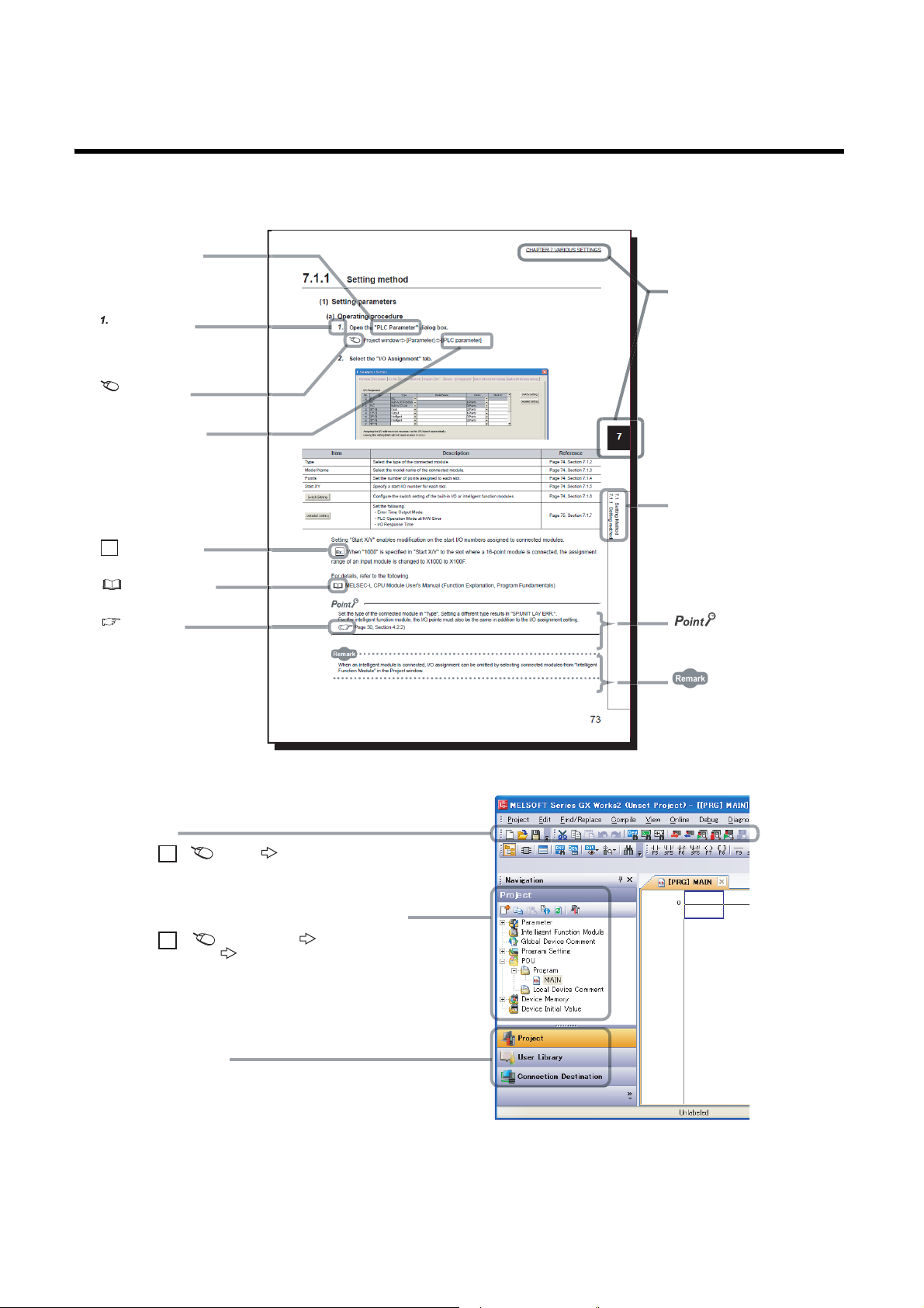
MANUAL PAGE ORGANIZATION
The section of
the current page is shown.
The chapter of
the current page is shown.
"" is used for
screen names and items.
[ ] is used for items
in the menu bar and
the project window.
shows operating
procedures.
shows reference
manuals.
shows notes that
requires attention.
shows mouse
operations.
*1
shows
reference pages.
shows setting or
operating examples.
Ex.
shows useful
information.
A window selected in the view selection area is displayed.
View selection area
[Online] [Write to PLC...]
Select [Online] on the menu bar,
and then select [Write to PLC...].
Project window
[Parameter]
[PLC Parameter]
Select [Project] from the view selection
area to open the Project window.
Menu bar
Ex.
Ex.
In the Project window, expand [Parameter] and
select [PLC Parameter].
In this manual, pages are organized and the symbols are used as shown below.
The following illustration is for explanation purpose only, and should not be referred to as an actual documentation.
*1 The mouse operation example is provided below.
14
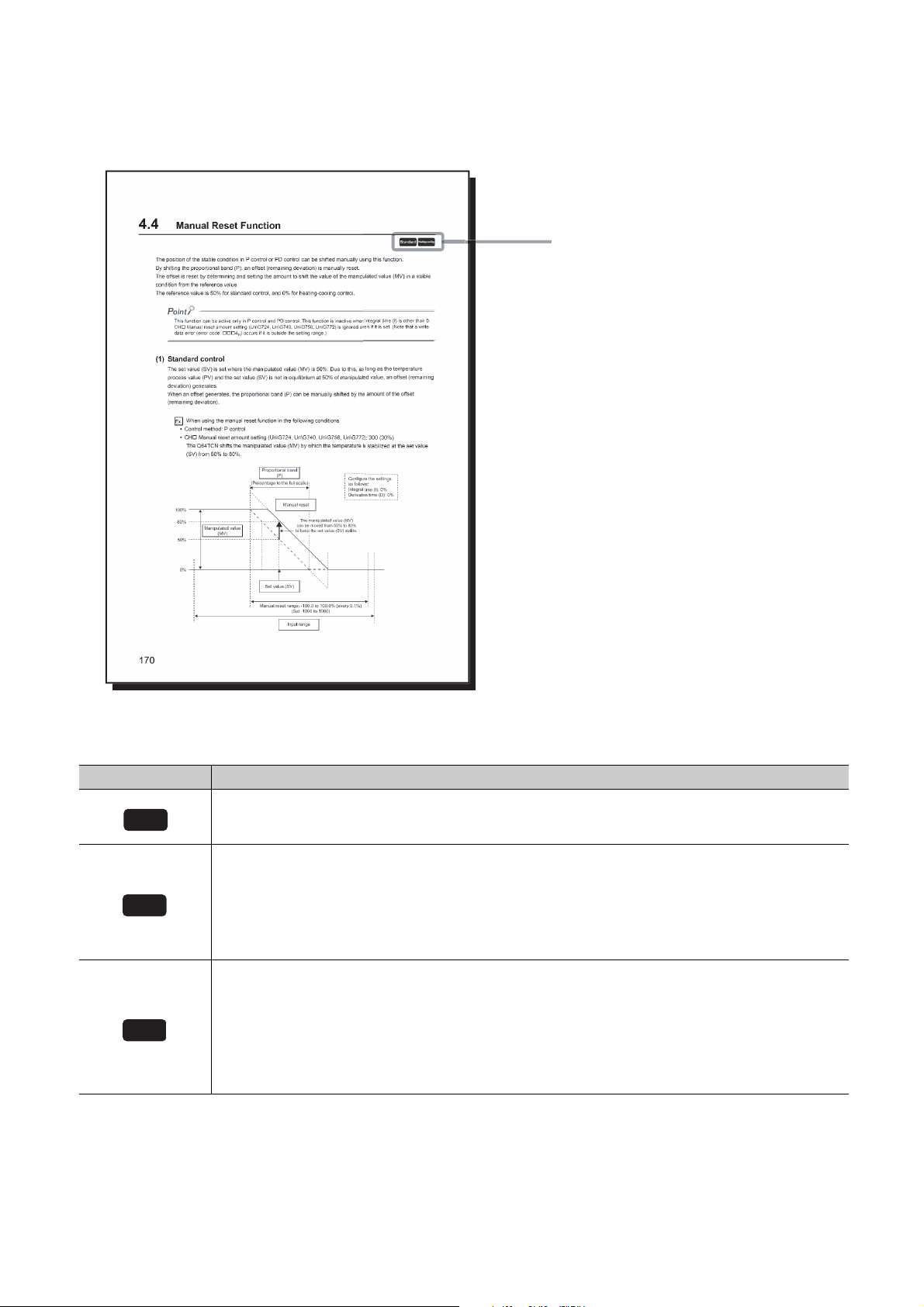
Pages describing buffer memory areas and functions are organized as shown below.
These icons indicate control modes
that can be used.
Common
Standard
Heating-cooling
The following illustration is for explanation purpose only, and should not be referred to as an actual documentation.
The following table describes the meaning of each icon.
Icon Meaning
This icon means that the buffer memory area or function can be used in all control modes.
This icon means that the buffer memory area or function for temperature control can be used in the standard
control.
The buffer memory area and function can be used in the following control modes and channels:
• CH1 to CH4 in the standard control
• CH3 and CH4 in the mix control (normal mode)
• CH3 and CH4 in the mix control (expanded mode)
This icon means that the buffer memory or function for temperature control can be used in the heating-cooling
control.
The buffer memory area and function can be used in the following control modes and channels:
• CH1 and CH2 in the heating-cooling control (normal mode)
• CH1 to CH4 in the heating-cooling control (expanded mode)
• CH1 in the mix control (normal mode)
• CH1 and CH2 in the mix control (expanded mode)
15

TERMS
Unless otherwise specified, this manual uses the following terms.
Term Description
Q64TCTTN The abbreviation for the Q64TCTTN temperature control module
Q64TCTTBWN
Q64TCRTN The abbreviation for the Q64TCRTN temperature control module
Q64TCRTBWN
Q64TCN A generic term for the Q64TCTTN, Q64TCTTBWN, Q64TCRTN, and Q64TCRTBWN
PID constants A generic term for the proportional band (P), integral time (I), and derivative time (D)
Temperature sensor A generic term for thermocouples and platinum resistance thermometers
Control method
Control mode
Fixed value action The operating status of when the set value (SV) is fixed
Full scale
Ramp action The operating status of when the set value (SV) is constantly changed
Number of loops
QCPU Another term for the MELSEC-Q series CPU module
Redundant CPU A generic term for the Q12PRHCPU and Q25PRHCPU
External input The abbreviation for input from connectors for external devices
External output The abbreviation for output to connectors for external devices
Programming tool A generic term for GX Works2 and GX Developer
GX Works2
GX Developer
GX Configurator-TC
Buffer memory
The abbreviation for the Q64TCTTBWN temperature control module with the
disconnection detection function
The abbreviation for the Q64TCRTBWN temperature control module with the
disconnection detection function
A generic term for two-position control, P control, PI control, PD control, and PID
control
A generic term for the standard control, heating-cooling control (normal mode),
heating-cooling control (expanded mode), mix control (normal mode), and mix control
(expanded mode)
A full input range. For example, when the selected input range is
-200.0°C to 400.0°C, the full scale is 600.0.
The number of feedback control systems (closed-loop control systems) that can be
configured using one module. Under the standard control, one loop consists of one
input and one output. Under the heating-cooling control, one loop consists of one input
and two outputs.
The product name of the software package for the MELSEC programmable
controllers
A setting and monitoring tool added in GX Developer (for temperature control
modules)
The memory of an intelligent function module used to store data (such as setting
values and monitored values) for communication with a CPU module
PACKING LIST
The following items are included in the package of this product.
Model Item name Quantity
Q64TCTTN Q64TCTTN temperature control module 1
Q64TCTTBWN Q64TCTTBWN temperature control module with the disconnection detection function 1
Q64TCRTN Q64TCRTN temperature control module 1
Q64TCRTBWN Q64TCRTBWN temperature control module with the disconnection detection function 1
Q64TCTTN/RTN-U-HW Before Using the Product 1
16
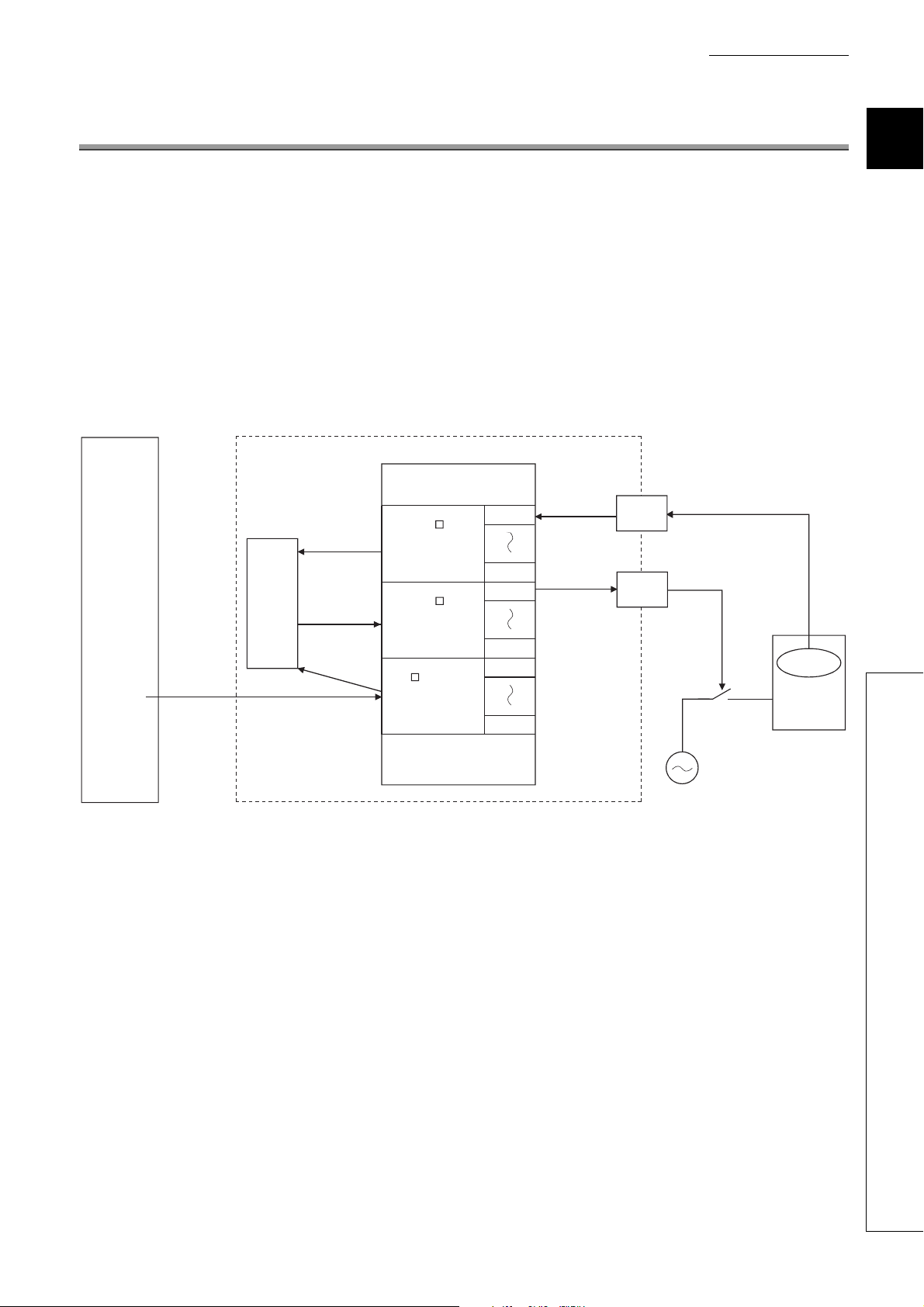
CHAPTER 1 OVERVIEW
Buffer memory
Programmable
controller CPU Q64TCTTN, Q64TCRTN
Initial
setting
(To instruction)
Set value (SV)
Set value (SV)
PID
operation
Temperature
process
value (PV)
Temperature
process
value (PV)
Manipulated
value (MV)
Manipulated
value (MV)
Temperature
Device to be
controlled
Input from temperature sensor
Transistor output
(ON/OFF pulse)
CH1
CH4
CH4
CH4
CH1
CH1
CH1
CH1
CH
Temperature
process value (PV)
(Un\G9 to Un\G12)
CH
Manipulated value
(MV)
(Un\G13 to Un\G16)
CH
Set value
(SV) setting
(Un\G34, Un\G66,
Un\G98, Un\G130)
This chapter describes the overview of the Q64TCN.
(1) The Q64TCTTN and Q64TCRTN
• The Q64TCTTN and Q64TCRTN perform PID operation to reach the target temperature based on input from
an external temperature sensor. The modules control temperature by transistor output.
• The Q64TCTTN and Q64TCRTN possess the auto tuning function by which proportional band (P), integral
time (I) and derivative time (D) for PID operation are automatically set.
• The Q64TCTTN accepts type K, J, T, B, S, E, R, N, U, L, PL II, and W5Re/W26Re thermocouples. The
Q64TCRTN accepts type Pt100 and JPt100 platinum resistance thermometers.
CHAPTER 1 OVERVIEW
1
17
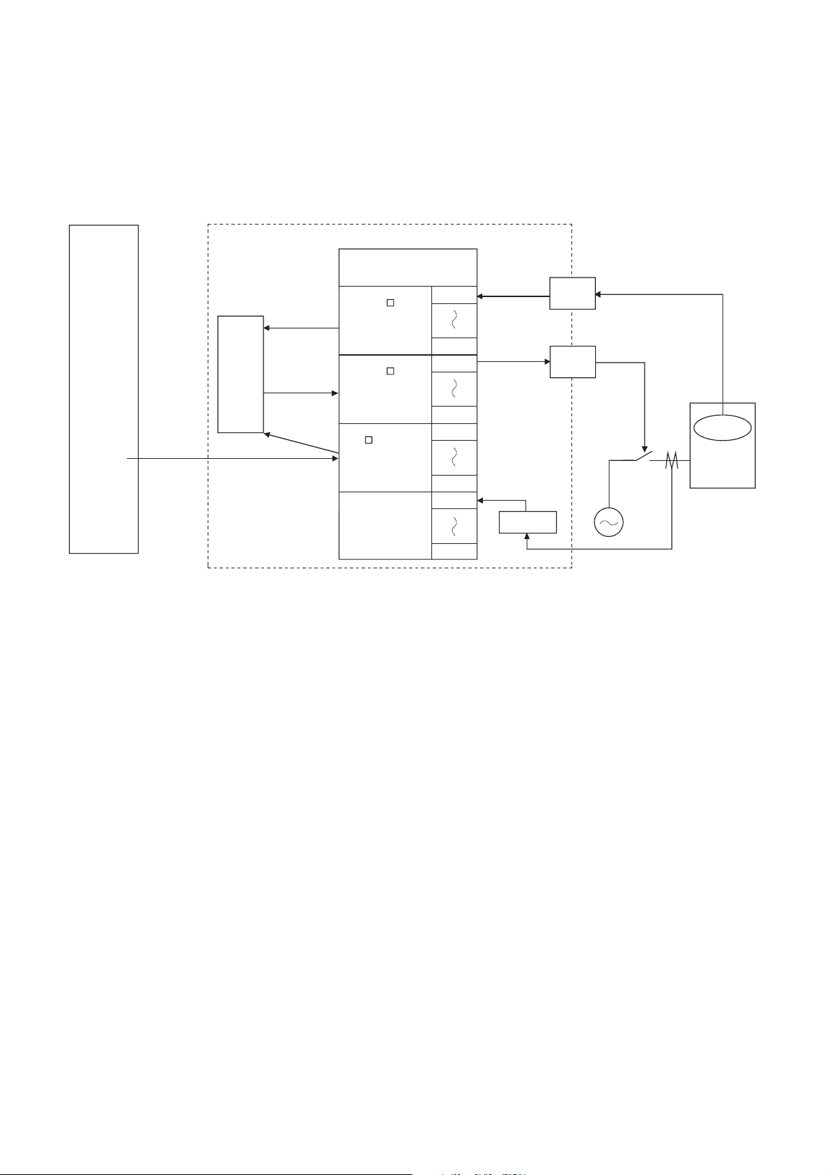
(2) The Q64TCTTBWN and Q64TCRTBWN
Buffer memory
Programmable
controller CPU
Initial
setting
(To instruction)
Set value (SV)
Set value (SV)
PID
operation
Temperature
process
value (PV)
Manipulated
value (MV)
Manipulated
value (MV)
Temperature
Device to be
controlled
Input from temperature sensor
Transistor output
(ON/OFF pulse)
CH1
CH4
CH4
CH4
CH1
CH1
CH1
CH1
Q64TCTTBWN, Q64TCRTBWN
CH4
CH1
Current
sensor
Disconnection
detection
Alarm
Temperature
process
value (PV)
CH
Temperature
process value (PV)
(Un\G9 to Un\G12)
CH
Manipulated value
(MV)
(Un\G13 to Un\G16)
CH
Set value
(SV) setting
(Un\G34, Un\G66,
Un\G98, Un\G130)
The Q64TCTTBWN and Q64TCRTBWN are Q64TCTTN and Q64TCRTN-based modules which possess an
additional function to detect heater disconnection using input from external current sensors.
18

CHAPTER 1 OVERVIEW
1.1 Features
(1) Optimum temperature adjustment control (PID control)
• The Q64TCN performs temperature adjustment control automatically when the user simply sets PID
constants necessary for PID operation: proportional band (P), integral time (I), derivative time (D), and
temperature set value (SV). No special instruction is necessary to perform PID control.
• Using the auto tuning function or self-tuning function enables the PID constants to be set automatically.
Complicated PID operational expressions to determine PID constants are not necessary.
(2) Selection of control mode
A control mode can be selected from the standard control (heating or cooling), heating-cooling control (heating
and cooling), or mix control (combination of the standard control and heating-cooling control).
(3) Four loops on one module
The maximum of four loops of temperature adjustment control can be performed simultaneously. In addition, loop
control can be performed using analog modules on the base unit or the network; input from an A/D converter
module or output to a D/A converter module can be processed.
(4) Simultaneous temperature rise of multiple loops
Temperatures of multiple loops can be adjusted to simultaneously reach the set value of each; temperatures are
controlled evenly without any partial heat exaggeration. This function saves energy and cost.
1
(5) Suppression of peak current
Current flows into a heater can be suppressed by controlling output so that each channel's output does not turn
on at the same time as other channels.
This function saves energy and cost.
(6) RFB limiter function
The RFB (Reset feed back) limiter suppresses overshoot which is liable to occur at a startup or when a
temperature process value (PV) is increased.
(7) Correction of temperature process value (PV)
The difference between the temperature process value (PV) and actual temperature can be corrected easily
using the following functions.
• Normal sensor correction (one-point correction) function: Corrects the difference by setting the rate of
correction value to the full scale of the input range.
• Sensor two-point correction function: Corrects the difference based on the inclination of the line on the two
points set in advance.
• Primary delay digital filter setting: Smoothens transient noise, and absorbs drastic change.
(8) E2PROM for backing up set values
The set values in the buffer memory, such as the setting related to PID control, can be stored into E2PROM for
data backup. The values do not need to be reset after turning the power on from off or releasing the CPU module
from its reset status.
Using the test function of the programming tool to write data directly to the buffer memory, the minimum
sequence program required is "LD**" + "OUT Yn1".
1.1 Features
19

(9) Detection of disconnection
Heater disconnection can be detected easily by the loop disconnection detection function.
The Q64TCTTBWN and Q64TCRTBWN can detect the disconnection of a heater accurately.
(10)Easy setting by GX Works2
Sequence program can be reduced by configuring the default setting or auto refresh setting on the screen. Also,
the setting status or operating status of the module can be checked easily.
20
CHAPTER 1 OVERVIEW
Set value data
storage area
Temperature
process value
data storage area
PID operation
Manipulated
value data storage
area
Temperature
sensor
Control
object
Q64TCN
Set value
(SV)
Temperature
process
value (PV)
Manipulated
value (MV)
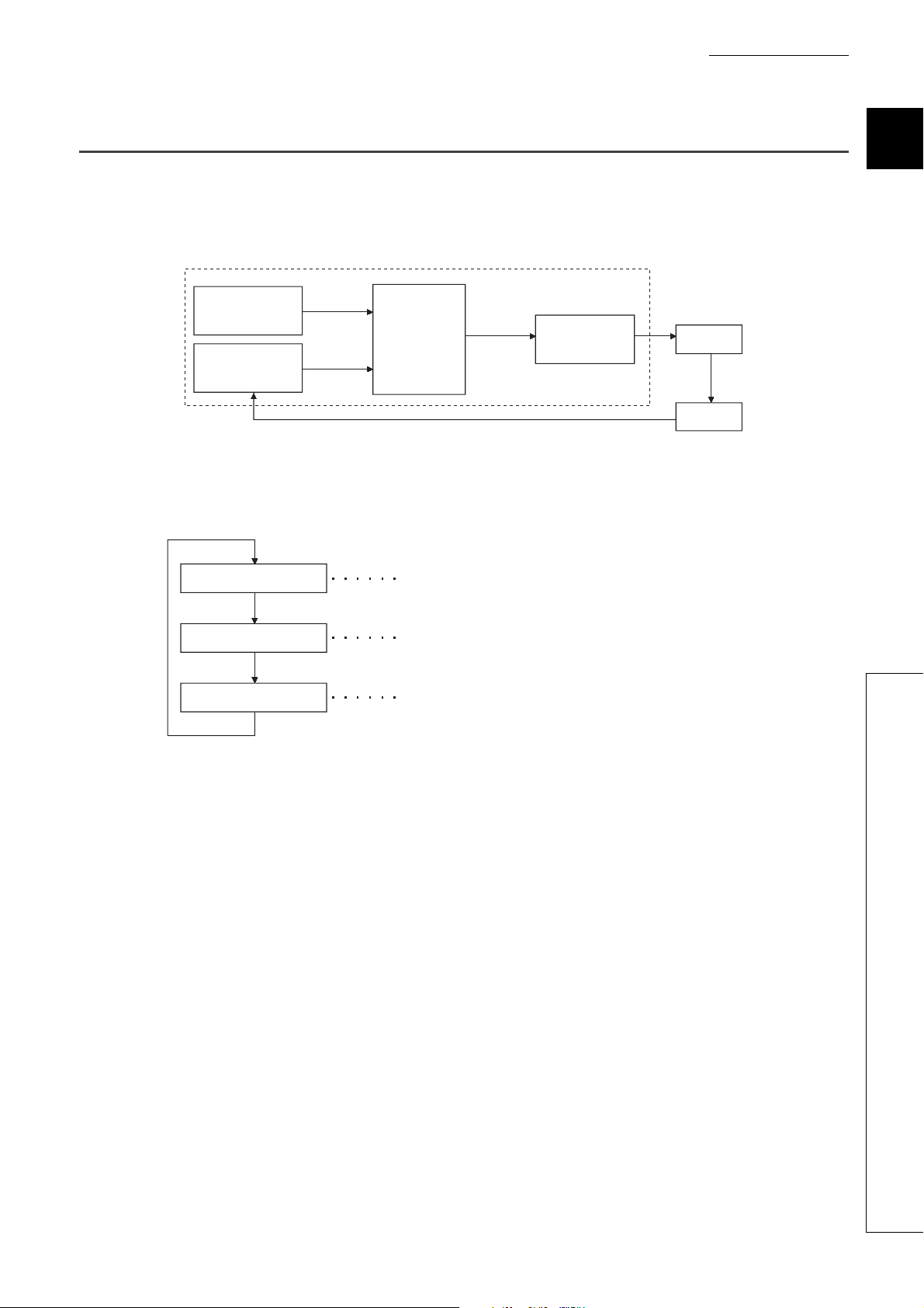
Import a signal from the temperature sensor and write it to the temperature
process value data storage area as a temperature process value (PV).
Perform PID operation using the Set value (SV)/temperature process
value (PV) values in the set value/temperature process value data
storage area.
Convert manipulated value (MV) obtained by the PID operation to
transistor-output on time and output it.
Read the temperature
process value (PV)
Perform PID operation
Output the manipulated
value (MV)
1.2 The PID Control System
(1) PID control system
The following figure shows a system of when performing the PID control.
(2) PID control procedure
The PID control is performed in the following procedure.
1
1.2 The PID Control System
21
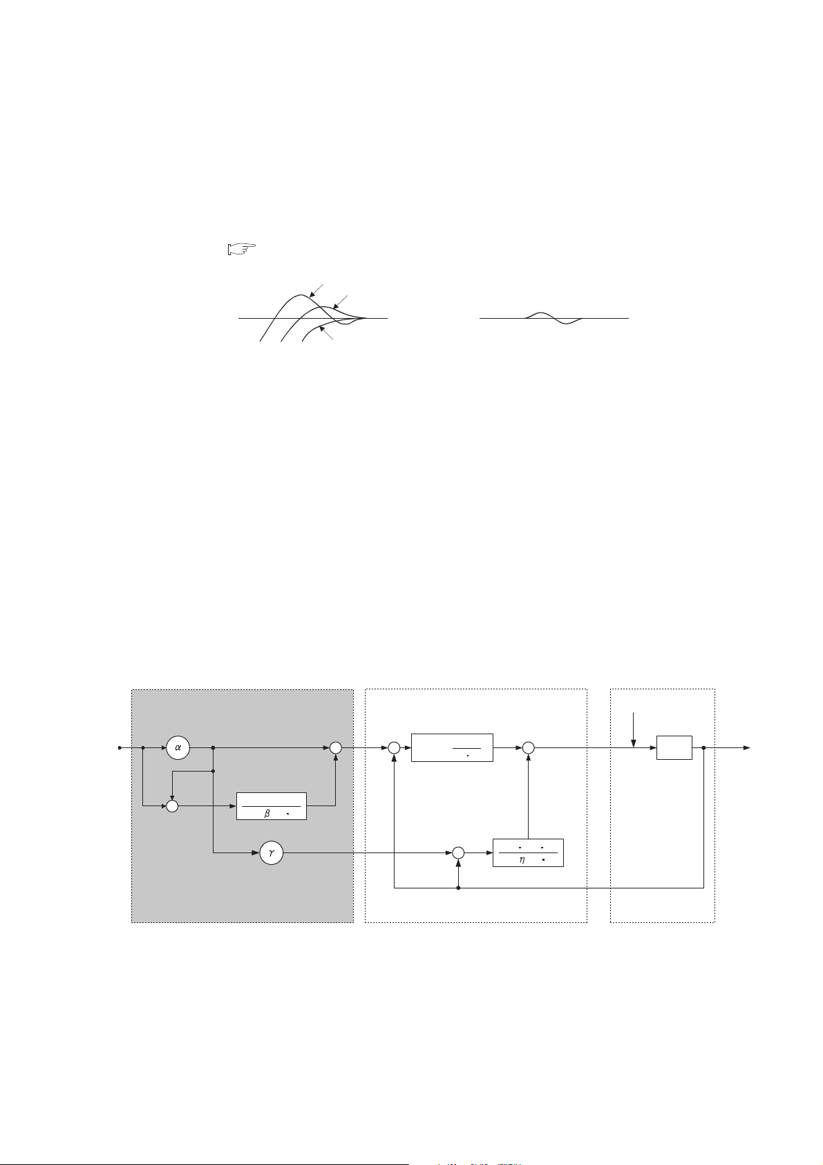
(3) PID control (simple two-degree-of-freedom)
PID control
Object to be
controlled
Disturbance D
1
1 + T
I s
1 + TD s
KP TD s
1
T
I s
KP (1 + )
Added function for two-degree-of-freedom
Manipulated
value (MV)
Set value
(SV)
G(s)
Temperature
process value (PV)
-
+
-
+
+
+
+
+
+
-
The Q64TCN operates in "simple two-degree-of-freedom". In this form of PID control, parameters are simplified
compared to the two-degree-of-freedom PID control.
In the simple two-degree-of-freedom, the module controls the target subject using not only PID constants but also
the control response parameter. The parameter can be set to "fast", "normal", or "slow". This setting enables the
form of "response to the change of the set value (SV)" to change maintaining "response to the disturbance" in a
good condition. ( Page 188, Section 4.7)
Fast
Normal
Set value
(SV)
Slow
Response to the change
of the set value (SV)
The following explains the difference between the one-degree-of-freedom PID control, two-degree-of-freedom
PID control, and simple two-degree-of-freedom PID control.
(a) One-degree-of-freedom PID control and two-degree-of-freedom PID control
• General PID control is called one-degree-of freedom PID control. In the one-degree-of freedom PID
control, when PID constants to improve "response to the change of the set value (SV)" are set, "response
to the disturbance" degrades. Conversely, when PID constants to improve "response to the disturbance"
are set, "response to the change of the set value (SV)" degrades.
• In the two-degree-of-freedom PID control, a manipulated value (MV) is determined considering the set
value (SV) or variations. In this form of PID control, "response to the change of the set value (SV)" and
"response to the disturbance" can be compatible with each other.
Set value
(SV)
Response to the disturbance
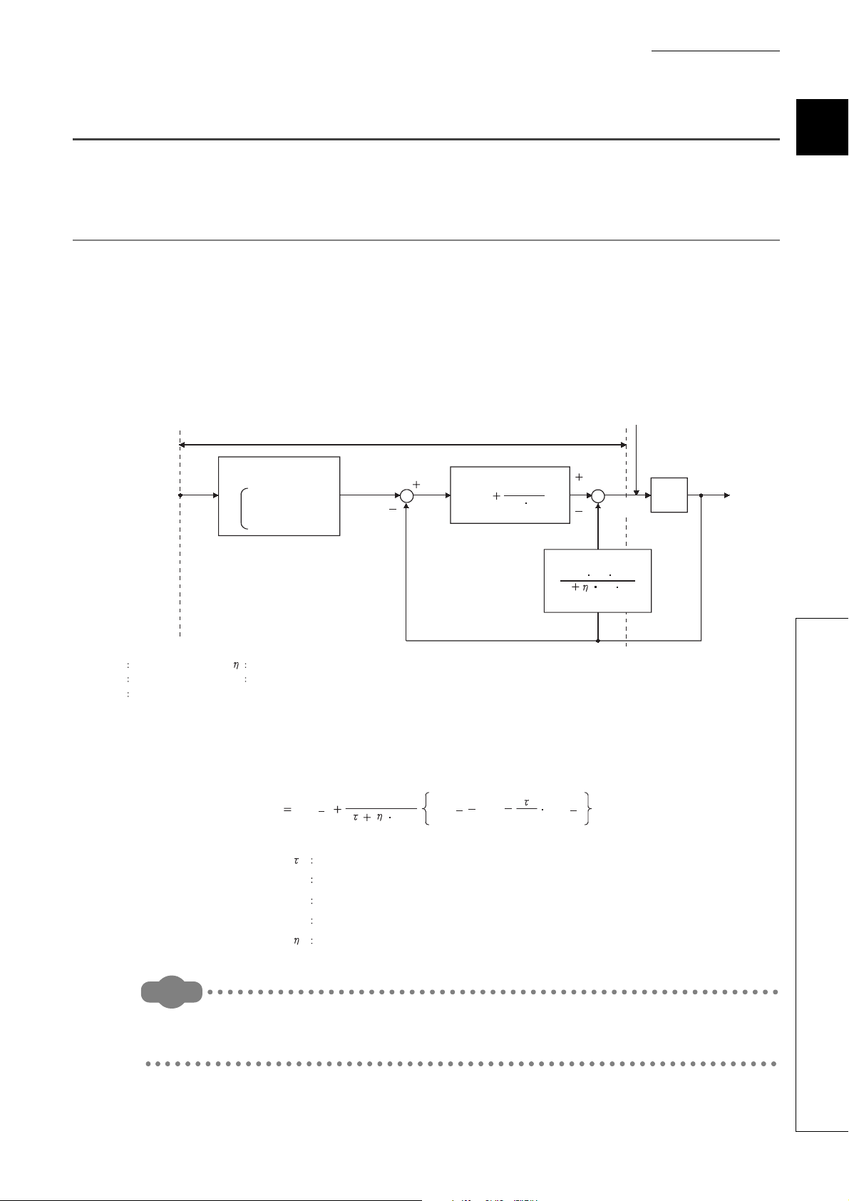
(b) Two-degree-of-freedom PID control and simple two-degree-of-freedom PID control
The following figure is a block diagram of the two-degree-of-freedom PID control.
By setting , , and above properly, optimum control can be achieved.
Note that required parameter settings increase and PID constants can hardly be auto-set by the auto tuning
function for complete two-degree-of-freedom PID control. Therefore, the Q64TCN operates in the simple two-
degree-of-freedom PID control for which parameters are simplified.
22
CHAPTER 1 OVERVIEW
Remark
Q64TCN
Control object
Slow
Normal
Fast
1
Disturbance D
G(s)
K
P TD s
1
TD s
Temperature
process value (PV)
Laplace transform conversion
DerivativeProportional gain
Integral time
Derivative time
Set value (SV)
K
P (1 )
Control response
parameters
TI s
KP
TI
TD
s
Manipulated
value (MV)
Sampling cycle
Incomplete derivative output
Temperature process value (PV)
Derivative time
Derivative
MV
n MVn 1
TD
(PV
n 1 PVn)
T
D
MVn 1
MV
PV
T
D
TD
1.3 About the PID Operation
The Q64TCN can perform PID control in process-value incomplete derivation.
1.3.1 Operation method and formula
The PID control in process-value incomplete derivation is an operation method which puts a primary delay filter on
input from a derivative action and eliminate high-frequency noise component in order to perform a PID operation on
the deviation (E).
(1) Algorithm of PID control in process-value incomplete derivation
The algorithm of PID control in process-value incomplete derivation is shown below.
1
(2) Formula
The formula used for the Q64TCN is shown below.
The PID control in process-value derivation is an operation method which uses the process value (PV) for the derivation
section in order to perform a PID operation. Not using deviation for the derivation section, drastic output change due to a
derivative action is reduced when deviation varies along with the setting value change.
23
1.3 About the PID Operation
1.3.1 Operation method and formula
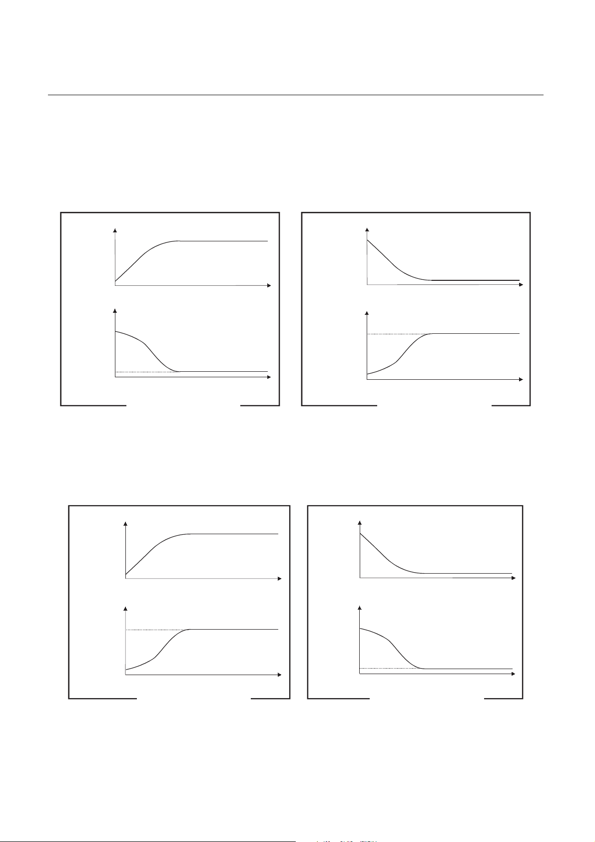
1.3.2 The Q64TCN actions
Manipulated
value
Manipulated
value
Temperature Temperature
Time
Time
Time
Time
Set value < Starting temperature Set value > Starting temperature
Set
value
Set
value
Manipulated
value
Temperature
Time
Time
Time
Time
Manipulated
value
Temperature
Set
value
Set value > Starting temperature Set value < Starting temperature
Set
value
The Q64TCN performs PID operations in forward actions and reverse actions.
(1) Forward action
In a forward action, the manipulated value (MV) is increased when the temperature process value (PV) increases
from the set value (SV).
A forward action is used for cooling control.
(2) Reverse action
In a reverse action, the manipulated value is increased when the temperature process value (PV) decreases from
the set value (SV).
A reverse action is used for heating control.
24

CHAPTER 1 OVERVIEW
E
Time
Time
Deviation
(E)
Manipulated
value (MV)
K
P E
Set value
(SV)
Set value
(SV)
Temperature process value (PV) Temperature process value (PV)
Offset
TimeTime
Offset
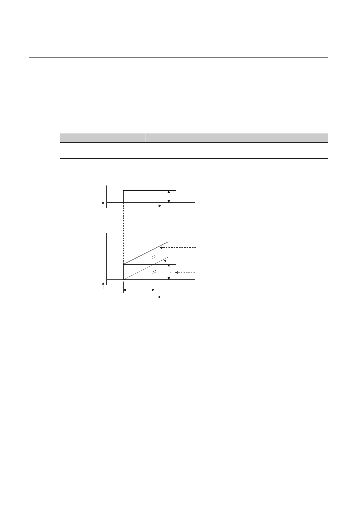
1.3.3 Proportional action (P-action)
A proportional action is an action to obtain the manipulated value (MV) proportional to the deviation (difference
between the set value (SV) and the process value (PV)).
(1) Proportional gain
In a proportional action, the relationship between changes in the deviation (E) and the manipulated value can be
expressed in the following formula:
MV = K
P•E
where Kp is a proportional constant and is called proportional gain. The manipulated value (MV) varies in the
range from -5.0% to 105.0%.
The following table describes the difference of actions depending on the value of Kp, proportional gain.
Condition Proportional action
Kp is a small value The control action slows down.
Kp is a large value
The following figure shows a proportional action of step responses where the deviation (E) is a fixed value.
The control action speeds up, though the temperature process value (PV) tends to
fluctuate around the set value.
1
(2) Offset
The certain amount of difference generates between the temperature process value (PV) and the set value (SV)
is called an offset (remaining deviation).
In an proportional action, an offset (remaining deviation) generates.
1.3 About the PID Operation
1.3.3 Proportional action (P-action)
25
1.3.4 Integral action (I-action)
An integral action is an action which continuously changes the manipulated value (MV) to eliminate the deviation (E)
when there is any.
The offset caused by a proportional action can be eliminated.
In an integral action, the time from a deviation occurrence until when the manipulated value (MV) of the integral action
becomes equals to that of the proportional action is called integral time, and is indicated as TI.
The following table describes the difference of actions depending on the value of T
Condition Integral action
TI is a small value
I is a large value The integral effect gets small, and time to eliminate the offset gets long.
T
The integral effect gets large, and time to eliminate the offset gets short.
Though, the temperature process value (PV) tends to fluctuate around the set value.
The following figure shows an integral action of step responses where the deviation (E) is a fixed value.
I, integral time.
Deviation
(E)
Manipulated
value (MV)
T
I
Time
K
P E
Time
E
Manipulated value of the Proportional action + Integral action
Manipulated value of the Integral action
Manipulated value of the Proportional action
An integral action is used as a PI action in combination with a proportional action, or PID action in combination with a
proportional and derivative actions.
An integral action cannot be used by itself.
26

CHAPTER 1 OVERVIEW
E
Manipulated value of the Proportional action
T
D
Time
Time
Deviation
(E)
Manipulated
value (MV)
K
P E
1.3.5 Derivative action (D-action)
A derivative action adds the manipulated value (MV) proportional to the rate of change to eliminate the deviation (E)
when it occurs.
A derivative action can prevent the control target from changing significantly due to disturbance.
In a derivative action, the time from a deviation occurrence until when the manipulated value (MV) of the derivative
action becomes equals to that of the proportional action is called derivative time, and is indicated as TD.
The following table describes the difference of actions depending on the value of T
Condition Derivative action
TD is a small value The derivative effect gets small.
The derivative effect gets large.
T
D is a large value
Though, the temperature process value (PV) tends to fluctuate around the set value
in short cycles.
The following figure shows a derivative action of step responses where the deviation (E) is a fixed value.
D, derivative time.
1
A derivative action is used as a PD action in combination with a proportional action, or PID action in combination with
a proportional and integral actions.
A derivative action cannot be used by itself.
1.3 About the PID Operation
1.3.5 Derivative action (D-action)
27

1.3.6 PID action
PID action
I action
P action
D action
PI action
Deviation
(E)
Manipulated
value (MV)
Time
Time
A PID action performs control using the manipulated value (MV) calculated by merging the proportional action, integral
action, and derivative action.
The following figure shows a PID action of step responses where the deviation (E) is a fixed value.
28
Loading...