


Air Conditioners For Building Application
Outdoor Unit
PURY-RP200YJM-A (-BS) |
|
PURY-RP250YJM-A (-BS) |
|
PURY-RP300YJM-A (-BS) |
For use with R410A |
|
MINERAL OIL COLLECTION (REFRIGERANT OIL RECOVERY) INSTRUCTIONS MANUAL
ANLEITUNGSHANDBUCH FÜR DIE MINERALÖLSAMMLUNG (KÄLTEMITTELÖLENTNAHME)
MANUEL D’INSTRUCTIONS POUR LA COLLECTE D’HUILE MINÉRALE (RÉCUPÉRATION DE L’HUILE FRIGORIFIQUE)
MANUAL DE INSTRUCCIONES PARA LA RECOGIDA DE ACEITE MINERAL (RECUPERACIÓN DE ACEITE REFRIGERANTE)
RACCOLTA DELL’OLIO MINERALE (RECUPERO DELL’OLIO REFRIGERANTE) MANUALE DI ISTRUZIONI
MANUAL DE INSTRUÇÕES DE RECOLHA DE ÓLEO MINERAL (RECUPERAÇÃO DO ÓLEO REFRIGERANTE)
P I E F D GB
, PURY-RP250YJM-A (-BS), PURY-RP300YJM-A (-BS) Installation Manual")
1. Unit Components
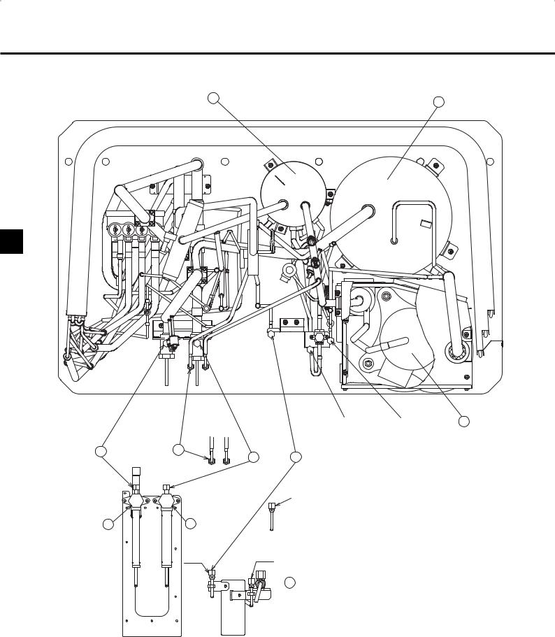
Figure 1 Top view of the refrigerant pipes inside an outdoor unit
H I
GB
CJ2 CJ1
C B
D A
CJ5
F G
CJ3 CJ4
 E
E
Figure 2 Valve types allocations
CJ4 |
CJ5 |
J |
A: Refrigerant charge port (for automatic charging only)
B: Check joint on the low-pressure side
A port through which additional refrigerant is charged after the completion of refrigerant oil recovery operation
C: Service port on the high-pressure valve Connecting port to the refrigerant circuit
•Evacuation port (high-pressure side)
•A port through which refrigerant for the indoor units is charged
D: Service port on the low-pressure valve Connecting port to the refrigerant circuit
•Evacuation port (low-pressure side)
•A port through which refrigerant for the
indoor units is charged
E: A valve to be closed after the completion of refrigerant oil recovery operation (BV3) (Be sure to close this valve after the completion of refrigerant oil recovery operation.)
F: High-pressure valve G: Low-pressure valve H: O/T
I: ACC
J: COMP
CJ3: Refrigerant charge port CJ4: Oil sampling port
CJ5: Refrigerant oil discharge port
2

2. Refrigerant Oil Recovery Operation Flow
2.1 Refrigerant oil recovery operation monitor display
1.How to read the LED on the service monitor
Units' operation status can be monitored on the LED display by setting the dipswitches SW1-1 through 1-10 on the MAIN board of the outdoor units.
Four 7-segment LEDs are used to display numerical values, flags, and alphabets to display various information.
7SEG LED
GB
The LEDs display such information as pressure and temperature in numerical values and operating conditions and the ON/OFF status of solenoid valve as flags.
● Display of numerical values
Example:When the pressure sensor reads 18.8 kg/cm2G (Item No. 58)
*The unit of pressure is in kg/cm2G.
*Use the following conversion formula to convert the displayed value into a value in SI unit (MPa). SI unit (MPa) = Displayed value (kg/cm2G) u0.098
● Flag display (Each set of two lines in vertical alignment indicates a flag.) Example:Outdoor unit in the 3-minute restart delay mode. (Item No. 14)
|
|
|
|
|
|
|
|
LD1 |
|
LD2 |
LD3 |
LD4 LD5 LD6 LD7 |
LD8 |
|
|
|
|||||||||
|
|
|
|
|
|
|
|
|
|
|
|
|
|
|
|
|
|
|
|
|
|
|
|||
2. Table of items that can be monitored on the LED on the outdoor unit circuit board |
|
|
|
|
|
|
|
|
|
||||||||||||||||
|
|
|
|
|
|
|
|
|
|
|
|
|
|
|
|
|
|
|
|
|
|
|
|
|
|
|
|
|
|
|
|
|
|
|
|
|
|
|
|
|
|
|
|
|
|
|
|
|
|
|
|
No |
|
|
|
|
SW1 |
|
|
|
|
|
|
|
Display content |
|
|
|
LED display |
|
|
Notes |
|||||
|
|
|
|
|
|
|
|
|
|
|
|
|
|
|
|
|
|
|
|
|
|
|
|||
1 |
2 |
3 |
4 |
5 |
6 |
7 |
8 |
|
9 |
|
10 |
|
LD1 |
LD2 |
LD3 |
LD4 |
LD5 |
LD6 |
LD7 |
LD8 |
LD9 |
LD10 |
|||
|
|
|
|
|
|
||||||||||||||||||||
|
|
|
|
|
|
|
|
|
|
|
|
|
|
|
|
|
|
|
|
|
|
|
|
|
|
58 |
0 |
1 |
0 |
1 |
1 |
1 |
0 |
0 |
|
0 |
|
0 |
High pressure (kgf/cm2G) |
|
|
|
-99.9 to 999.9 |
|
|
|
|||||
59 |
1 |
1 |
0 |
1 |
1 |
1 |
0 |
0 |
|
0 |
|
0 |
Low pressure (kgf/cm2G) |
|
|
|
-99.9 to 999.9 |
|
|
|
|||||
60 |
0 |
0 |
1 |
1 |
1 |
1 |
0 |
0 |
|
0 |
|
0 |
Intermediate pressure |
|
|
|
-99.9 to 999.9 |
|
|
|
|||||
|
|
(kgf/cm2G) |
|
|
|
|
|
|
|||||||||||||||||
45 |
1 |
0 |
1 |
1 |
0 |
1 |
0 |
0 |
|
0 |
|
0 |
Discharge temperature (°C) |
|
|
|
-99.9 to 999.9 |
|
|
|
|||||
|
|
|
|
|
|
|
|
|
|
|
|
|
|
|
|
|
|
|
|
|
|||||
131 |
1 |
1 |
0 |
0 |
0 |
0 |
0 |
1 |
|
0 |
|
0 |
Refrigerant oil recovery operation |
|
|
|
rEP steps |
|
|
Reversed |
|||||
|
|
|
|
|
|
|
|
|
|
|
|
|
steps |
|
|
|
|
|
|
|
|
|
|
|
display |
122 |
0 |
1 |
0 |
1 |
1 |
1 |
1 |
0 |
|
0 |
|
0 |
Refrigerant oil recovery |
|
|
|
|
0 to 9999 |
|
|
|
||||
|
|
remaining time (*1) |
|
|
|
|
|
|
|
||||||||||||||||
|
|
|
|
|
|
|
|
|
|
|
|
|
Refrigerant oil recovery |
|
|
|
|
|
|
|
|
|
|
Reversed |
|
120 |
0 |
0 |
0 |
1 |
1 |
1 |
1 |
0 |
|
0 |
|
0 |
completion indicator flag |
|
|
|
S-1 (0) r-1 (0) (*2) |
|
|
||||||
|
|
|
|
|
|
|
|
|
|
|
|
|
Refrigerant charge adjustment |
|
|
|
|
|
|
|
|
|
|
display |
|
|
|
|
|
|
|
|
|
|
|
|
|
|
completion indicator flag |
|
|
|
|
|
|
|
|
|
|
|
|
(*1) The initial remaining time that indicates the refrigerant oil recovery is 80. A countdown will start on step 3 in the cooling mode. The countdown does not include the time for checking the refrigerant charge amount.
(*2) S-1: Refrigerant oil recovery complete, S-0: Refrigerant oil recovery incomplete,
r-1: Refrigerant charge adjustment complete, r-0: Refrigerant charge adjustment incomplete.
3

2.2 Procedures for refrigerant oil recovery
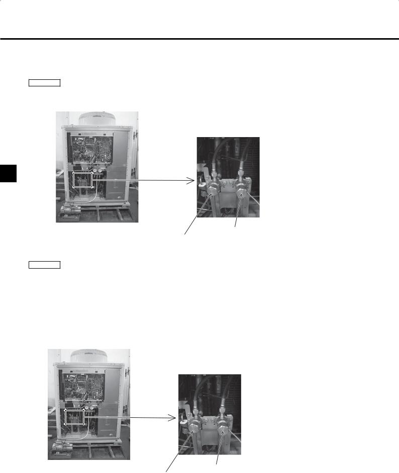
1Evacuating the existing pipes, and ensuring air tightness
Procedure 1 Charge airtight gas through the service port on both the high-pressure and low-pressure valves. The air tightness should be 4.15 MPa. After checking the air tightness, evacuate the air through the service port on both the high-pressure and low-pressure valves.
GB
Low-pressure valve
High-pressure valve
2Refrigerant charging
Procedure 2
•If the length or diameter of the refrigerant pipe is unknown
Charge the required amount of refrigerant (indoor units + BC controllers) through both high-pressure and low-pressure service port valves. •When refrigerant pipe diameter and length are already known
Charge the required amount of refrigerant (indoor units + BC controllers + pipes) through both the high-pressure and low-pressure service port valves. See the table below for the required amount of refrigerant for the indoor units and BC controllers. To calculate the required amount of refrigerant charged for the pipes, refer to 10.1. “Calculation of additional refrigerant charge” in the installation manual on the CD-ROM.
If there is excess refrigerant that cannot be charged, use it during oil recovery operation at step 4 (cooling operation).
Total capacity of |
Charged amount (kg) |
||
connected indoor units |
|||
|
|||
|
|
|
|
|
- 80 |
2.0 |
|
81 |
- 160 |
2.5 |
|
|
|
|
|
161 |
- 330 |
3.0 |
|
|
|
|
|
331 |
- 390 |
3.5 |
|
391 |
- 480 |
4.5 |
|
|
|
|
|
|
|
|
|
|
|
Charged amount per |
|
Total outdoor unit Model |
BC controller |
||
|
|
(Standard / Main) (kg) |
|
P200 |
2.0 |
||
|
|
||
P250 |
3.0 |
||
P300 |
|||
|
|||
|
|
|
|
Low-pressure valve
High-pressure valve
*After charging the required amount of refrigerant to the existing pipes, open the valve so that the pressure in the existing pipes and outdoor unit are equal. (Refer to Procedure 3.) Do not open the valve on the outdoor unit when the existing pipes are under vacuum. Doing so may cause the refrigerant that is dissolved in the refrigerant oil in the compressor to form and cause some oil to migrate to the existing pipes, resulting in insufficient lubrication.
4

3Opening the valves
Procedure 3 Open both the high-pressure and low-pressure valves.
Use a hexagonal wrench to open the valves. Refer to the table below for the proper wrench size.
Hexagonal wrench size
|
|
A |
|
|||
|
|
|
|
|
||
|
High- |
|
Low- |
|
|
|
|
pressure |
|
pressure |
|
||
8, 10, 12 HP |
8 mm |
|
8 mm |
|
|
|
GB |
||||||
|
|
|
|
|
||
|
|
|
|
|
||
|
|
|
|
|
|
|

 A
A
High-pressure valve
Low-pressure valve
4Connecting the refrigerant cylinder(s)
Procedure 4 If the required amount of refrigerant is not charged, disconnect the charging hose connected to the refrigerant cylinder from the service port on high-pressure and low-pressure side, and connect the charging hose to the refrigerant charge port CJ3
(only for automatic charging).
*Check that each cylinder has the correct amount of refrigerant.
*If the amount of refrigerant is insufficient, the units may stop during refrigerant oil recovery or it may take longer than usual to complete a test run.
Refrigerant charge port (CJ3)
5Setting the unit address and checking for proper system operation
Procedure 5 Set the unit address, turn on the power, and check for proper operation of the system.
*If an attempt is made to operate the outdoor unit before the refrigerant oil recovery operation is complete, an error code 7116 will appear on the remote controller. This does not indicate a malfunction. Wait for the oil recovery operation to be completed. The error code 7116 will go off upon completion of oil recovery operation.
5

GB
6Refrigerant oil recovery operation
Procedure 6 Set the dipswitches 3-1 and 4-8 to ON in that order. The compressor turns on, and oil recovery operation starts.
Procedure 7 The refrigerant oil recovery operation is explained in the next page. Wait for the operation to be automatically completed.
*If there was excess refrigerant that had not been charged at “2Refrigerant charging”, charge it during oil recovery operation at step 4 (cooling operation). After charging the refrigerant, close the valve on the refrigerant cylinder. (Even when the required amount of refrigerant is already charged, refrigerant charge is automatically adjusted.)
*If the cylinder runs out of refrigerant during the refrigerant oil recovery operation, continue the operation and replace the cylinder.
*If the cumulative oil recovery operation hour is more than three and a half hours, turn the dipswitches 4-8 and 3-1 to OFF to stop the operation and turn the dipswitches 4-7 on the units (OC) to OFF.
Wait for the operation to be automatically completed.
*Refer to the table at right for the maximum amount of refrigerant charge. Do not exceed the maximum amount.
If the refrigerant oil recovery operation does not finish after the maximum amount of refrigerant is charged, close the valve on refrigerant cylinder, and wait for the operation to be completed automatically.
*If the cylinder runs out of refrigerant during the refrigerant oil recovery operation, continue the operation and replace the cylinder.
I
Address switches |
|
|
|
|
|
Close the panel at |
SW5 |
||||
bottom front of the |
|
|
SW4 |
||
unit. |
OFF ON |
||||
|
|||||
SW3-1 |
|
|
|
|
1 |
|
|
|
|
||
|
|
|
|
||
|
|
|
|
|
2 |
|
|
|
|
|
|
|
|
|
|
|
3 |
|
|
|
|
|
|
|
|
|
|
|
4 |
|
|
|
|
|
|
|
|
|
|
|
5 |
|
|
|
|
|
|
|
|
|
|
|
6 |
|
|
|
|
|
|
|
|
|
|
|
7 |
|
|
|
|
|
|
|
|
|
|
|
8 |
|
|
|
|
|
|
|
|
|
|
|
9 |
|
|
|
|
|
|
|
|
|
|
|
10 |
|
|
|
|
|
|
|
|
|
|
|
|
|
SW3 |
||||
Outdoor unit capacity and the maximum amount of refrigerant charge
Outdoor unit
Maximum amount of refrigerant charge
capacity
(except for the indoor units and BC controllers) (kg)
RP200, 250, 300 |
20.0 |
LED monitor
SW3 |
SW1 |
Dipswitches |
SW2
Each dipswitch has 1 to 10 switches from the top. (OFF-left, ON-right)
(e.g., SW3-1 is the top switch of SW3. The figure at left indicates that only SW3-1 is set to ON.)
If the length or diameter of the refrigerant pipe is known, please make note of the following.
If more than the amount of refrigerant that you calculated is charged into the system in auto-charge mode, then there is no problem if you wish to close the cylinder valve while the unit is operating. The unit will stop operating of its own accord.
6

7Check for successful completion of the refrigerant oil recovery operation.
Procedure 8 Turn the dipswitches 1-4, 1-5, 1-6, and 1-7 to ON to verify that the refrigerant oil recovery operation is completed. “S-1” or “r-1” on the outdoor unit’s LED indicates a successful completion.
 LED
LED
GB
“S-1” “r-1”: The refrigerant oil recovery operation is successfully completed. Go to the next procedure.
“S-1” “r-0”: The refrigerant charge adjustment is not completed, but regular air conditioning operation can be started. If there was excess refrigerant that had not been charged, charge it through the low-pressure check joint (CJ2) during the air conditioning operation.
“S-0” “r-1”: The refrigerant oil recovery operation is not completed. To restart the refrigerant oil recovery operation, set the dipswitches 3-1 and 4-8 to ON in that order.
“S-0” “r-0”: The refrigerant oil recovery operation is not completed. To restart the refrigerant oil recovery operation, set the dipswitches 3-1 and 4-8 to ON in that order.
8Disconnecting the cylinder
Procedure 9 After completing the oil recovery operation, close the valve on the cylinder, and disconnect the cylinder within five minutes.
9Recording the amount of refrigerant that was charged
Procedure 10 Write on the control box panel the amount of refrigerant charged.
0Closing the valve on the connecting port to the refrigerant circuit
Procedure 11 Close BV3 completely. The refrigerant oil recovered from the existing pipes is sealed in an oil recovery vessel.
Turn the valve clockwise by 90 degrees. * Use a tool if necessary.
Compressor side
A B A
S O |
S O |
|
C |
Oil-recovery side |
|
<Factory setting> |
<After the oil-recovery test run> |
A Lever
B(Cap tightening torque: 20-25N•m (200-250 kg•cm))
C Rotation direction
7
1. Gerätekomponenten
Bild 1: Kältemittelleitungen eines Außengeräts in der Draufsicht
H I
D
CJ2 CJ1
C B
D A
CJ5
F G
CJ3 CJ4
 E
E
Bild 2: Ventiltypzuordnungen
CJ4 |
CJ5 |
J |
A: Kältemittelfüllanschluss (nur zum automatischen Befüllen)
B: Prüfverbindung an der Niederdruckseite
Ein Anschluss zum Nachfüllen von Kältemittel nach erfolgter Kältemittelölentnahme
C: Wartungsanschluss am Hochdruckventil Verbindungsanschluss zum Kältemittelkreis:
•Entlüftungsanschluss (Hochdruckseite)
•Ein Anschluss, über den Kältemittel für die Innengeräte aufgefüllt wird
D: Wartungsanschluss am Niederdruckventil Verbindungsanschluss zum Kältemittelkreis:
•Entlüftungsanschluss (Niederdruckseite)
•Ein Anschluss, über den Kältemittel für die Innengeräte aufgefüllt wird
E: Ein Ventil, das nach erfolgter Kältemittelölentnahme geschlossen werden muss (BV3)
(Sicherstellen, dass dieses Ventil nach erfolgter Kältemittelölentnahme geschlossen wird.)
F: Hochdruckventil
G: Niederdruckventil H: O/T
I: Akkumulator
J: Kompressor
CJ3: Kältemittelfüllanschluss CJ4: Ölprüfanschluss
CJ5: Kältemittelölablassanschluss
8

2. Arbeitsablauf bei der Kältemittelölentnahme
2.1 Monitoranzeige bei der Kältemittelölentnahme
1.Hinweise zum Lesen der LED am Wartungsmonitor
Der Betriebsstatus der Geräte kann an der LED-Anzeige durch Einstellen der Dip-Schalter SW1-1 bis 1-10 auf der Hauptplatine der Außengeräte überwacht werden.
Numerische Werte, Hinweissymbole und Buchstaben werden mit vier 7-Segment-LEDs angezeigt.
7-SEGMENT-LED
Die LEDs zeigen zum Beispiel Druckund Temperaturdaten als numerische Werte sowie Betriebszustände und den EIN/AUS-Status von Spulenventilen als Hinweissymbole an.
D
● Anzeige von numerischen Werten
Beispiel: Wenn der Drucksensor 18,8 kg/cm2G anzeigt (Punkt Nr. 58)
*Der Druck wird in kg/cm2G angezeigt.
*Der Anzeigewert kann anhand der folgenden Umrechnungsformel in SI-Einheiten (MPa) konvertiert werden. SI-Einheit (MPa) = Anzeigewert (kg/cm2G) u0,098
● Hinweissymbolanzeige (Jedes Set von zwei vertikal ausgerichteten Linien zeigt ein Symbol an.) Beispiel: Außengerät im Betriebszustand „Neustart 3 Minuten verzögert“. (Punkt Nr. 14)
|
|
|
|
|
|
|
|
LD1 |
|
LD2 |
LD3 |
LD4 LD5 LD6 |
LD7 |
LD8 |
|
|
|
|||||||||
|
|
|
|
|
|
|
|
|
|
|
|
|
|
|
|
|
|
|
|
|
|
|
||||
2. Tabelle der Punkte, die mit der LED an der Leiterplatte des Außengeräts überwacht werden können. |
|
|
|
|||||||||||||||||||||||
|
|
|
|
|
|
|
|
|
|
|
|
|
|
|
|
|
|
|
|
|
|
|
|
|
|
|
|
|
|
|
|
|
|
|
|
|
|
|
|
|
|
|
|
|
|
|
|
|
|
|
|
|
|
Nr. |
|
|
|
|
SW1 |
|
|
|
|
|
|
|
Anzeigeinhalt |
|
|
|
|
LED-Anzeige |
|
|
Hinweise |
|||||
|
|
|
|
|
|
|
|
|
|
|
|
|
|
|
|
|
|
|
|
|
|
|
|
|||
1 |
2 |
3 |
4 |
5 |
6 |
7 |
8 |
|
9 |
|
10 |
|
|
LD1 |
LD2 |
LD3 |
LD4 |
LD5 |
LD6 |
LD7 |
LD8 |
LD9 |
LD10 |
|||
|
|
|
|
|
|
|
||||||||||||||||||||
|
|
|
|
|
|
|
|
|
|
|
|
|
|
|
|
|
|
|
|
|
|
|
|
|
|
|
58 |
0 |
1 |
0 |
1 |
1 |
1 |
0 |
0 |
|
0 |
|
0 |
Hoher Druck (kgf/cm2G) |
|
|
|
|
-99,9 bis 999,9 |
|
|
|
|||||
59 |
1 |
1 |
0 |
1 |
1 |
1 |
0 |
0 |
|
0 |
|
0 |
Niedriger Druck (kgf/cm2G) |
|
|
|
|
-99,9 bis 999,9 |
|
|
|
|||||
60 |
0 |
0 |
1 |
1 |
1 |
1 |
0 |
0 |
|
0 |
|
0 |
Mittlerer Druck |
|
|
|
|
-99,9 bis 999,9 |
|
|
|
|||||
|
|
(kgf/cm2G) |
|
|
|
|
|
|
|
|||||||||||||||||
45 |
1 |
0 |
1 |
1 |
0 |
1 |
0 |
0 |
|
0 |
|
0 |
Ablasstemperatur (°C) |
|
|
|
|
-99,9 bis 999,9 |
|
|
|
|||||
|
|
|
|
|
|
|
|
|
|
|
|
|
|
|
|
|
|
|
|
|
|
|||||
131 |
1 |
1 |
0 |
0 |
0 |
0 |
0 |
1 |
|
0 |
|
0 |
Arbeitsschritte bei der |
|
|
|
|
rEP Schritte |
|
|
Umgekehrte |
|||||
|
|
|
|
|
|
|
|
|
|
|
|
|
Kältemittelölentnahme |
|
|
|
|
|
|
|
|
|
|
|
Anzeige |
|
122 |
0 |
1 |
0 |
1 |
1 |
1 |
1 |
0 |
|
0 |
|
0 |
Verbleibende Zeit bei der |
|
|
|
|
|
0 bis 9999 |
|
|
|
||||
|
|
Kältemittelölentnahme (*1) |
|
|
|
|
|
|
|
|
||||||||||||||||
|
|
|
|
|
|
|
|
|
|
|
|
|
Anzeigesymbol für |
|
|
|
|
|
|
|
|
|
|
|
|
|
|
|
|
|
|
|
|
|
|
|
|
|
|
abgeschlossene |
|
|
|
|
|
|
|
|
|
|
|
Umgekehrte |
|
120 |
0 |
0 |
0 |
1 |
1 |
1 |
1 |
0 |
|
0 |
|
0 |
Kältemittelölentnahme |
|
|
|
|
S-1 (0) r-1 (0) (*2) |
|
|
||||||
|
|
|
|
|
|
|
|
|
|
|
|
|
Anzeigesymbol für |
|
|
|
|
|
|
|
|
|
|
|
Anzeige |
|
|
|
|
|
|
|
|
|
|
|
|
|
|
abgeschlossene Anpassung der |
|
|
|
|
|
|
|
|
|
|
|
|
|
|
|
|
|
|
|
|
|
|
|
|
|
|
Kältemittelbefüllung |
|
|
|
|
|
|
|
|
|
|
|
|
|
(*1) Bei der Kältemittelölentnahme wird die verbleibende Zeit anfänglich als 80 angezeigt. Ein Countdown startet im Kühlbetrieb bei Schritt 3. Die Zeit zum Prüfen der Kältemittelfüllmenge ist im Countdown nicht eingeschlossen.
(*2) S-1: Kältemittelölentnahme abgeschlossen, S-0: Kältemittelölentnahme nicht abgeschlossen,
r-1: Anpassen der Kältemittelbefüllung abgeschlossen, r-0: Anpassen der Kältemittelbefüllung nicht abgeschlossen.
9
2.2 Kältemittelölentnahmeverfahren
1Entlüften der vorhandenen Rohrleitungen und gewährleisten der Luftdichtigkeit
Verfahren 1 Befüllen Sie das System über den Wartungsanschluss am Hochund Niederdruckventil mit Luftdichtigkeitsprüfgas.
Die Luftdichtigkeit sollte 4,15 MPa betragen. Entlüften Sie das System nach der Prüfung der Luftdichtigkeit über den Wartungsanschluss am Hochund Niederdruckventil.
D
Niederdruckventil
Hochdruckventil
2Kältemittelbefüllung
Verfahren 2
•Wenn die Länge oder der Durchmesser der Kältemittelrohrleitung unbekannt ist
Befüllen Sie das System mit der erforderlichen Menge von Kältemittel (Innengeräte + BC-Steuerungen) über die Hochund Niederdruckwartungsanschlussventile.
•Wenn der Durchmesser und die Länge der Kältemittelrohrleitung bekannt sind
Befüllen Sie das System mit der erforderlichen Menge von Kältemittel (Innengeräte + BC-Steuerungen + Leitungen) über die Hochund Niederdruckwartungsanschlussventile. Entnehmen Sie die für die Innengeräte und BC-Steuerungen erforderliche Menge von Kältemittel der Tabelle unten. Angaben zur Berechnung der zum Befüllen der Rohrleitungen erforderlichen Kältemittelmenge finden Sie unter 10.1. „Berechnen der Kältemittelnachfüllmenge“ im Installationshandbuch auf der CD-ROM.
Falls eine Restmenge von Kältemittel verbleibt, die nicht eingefüllt werden kann, kann diese bei der Ölentnahme in Schritt 4 (Kühlbetrieb) verwendet werden.
Gesamtkapazität |
|
||
der angeschlossenen |
Füllmenge (kg) |
||
Innengeräte |
|
||
|
- 80 |
2,0 |
|
|
|
|
|
81 |
- 160 |
2,5 |
|
|
|
|
|
161 |
- 330 |
3,0 |
|
331 |
- 390 |
3,5 |
|
|
|
|
|
391 |
- 480 |
4,5 |
|
|
|
|
|
|
|
|
|
Außengerätemodell |
Füllmenge je |
||
BC-Steuerung |
|||
(insgesamt) |
(Standard/Hauptgerät) |
||
|
|
(kg) |
|
P200 |
2,0 |
||
|
|
||
P250 |
3,0 |
||
|
|
||
P300 |
|||
|
|||
Niederdruckventil
Hochdruckventil
*Nach dem Befüllen der vorhandenen Rohrleitungen mit der erforderlichen Kältemittelmenge muss das Ventil geöffnet werden, um den Druck in den vorhandenen Rohrleitungen und dem Außengerät auszugleichen. (Siehe Verfahren 3.) Das Ventil am Außengerät darf nicht geöffnet werden, wenn die vorhandenen Rohrleitungen unter Unterdruck stehen. Andernfalls könnte das im Kältemittelöl gelöste Kältemittel im Kompressor ausschlagen, einen Teil des Öls in die vorhandenen Rohrleitungen verdrängen und in einer unzureichenden Schmierung resultieren.
10
3Öffnen der Ventile
Verfahren 3 Öffnen Sie das Hochund das Niederdruckventil.
Verwenden Sie zum Öffnen der Ventile einen Sechskantschlüssel. Die geeignete Schlüsselgröße kann der untenstehenden Tabelle entnommen werden.
Sechskantschlüsselgröße
|
|
A |
|
|
|
|
|
|
Hoher |
|
Niedriger |
|
Druck |
|
Druck |
8, 10, 12 HP |
8 mm |
|
8 mm |
|
|
|
|
D

 A
A
Hochdruckventil
Niederdruckventil
4Anschließen der/des Kältemittelzylinder/s
Verfahren 4 Wenn das System nicht mit der erforderlichen Kältemittelmenge befüllt ist, muss der am Kältemittelzylinder angeschlossene Füllschlauch vom Wartungsanschluss an der Hochoder Niederdruckseite abgetrennt und am Kältemittelfüllanschluss CJ3 angeschlossen werden (nur bei automatischer Befüllung).
*Vergewissern Sie sich, dass jeder Zylinder die korrekte Kältemittelmenge enthält.
*Bei einer unzureichenden Kältemittelmenge können die Geräte während der Kältemittelölentnahme stoppen oder das Durchführen des Testbetriebs kann länger als gewöhnlich dauern.
Kältemittelfüllanschluss (CJ3)
5Einstellen der Geräteadresse und prüfen des ordnungsgemäßen Systembetriebs
Verfahren 5 Stellen Sie die Geräteadresse ein, schalten Sie die Stromversorgung ein und prüfen Sie das System auf seinen ordnungsgemäßen
Betrieb.
*Wenn versucht wird, das Außengerät in Betrieb zu nehmen, bevor die Kältemittelölentnahme abgeschlossen ist, erscheint an der Fernbedienung der Fehlercode 7116. Dies weist nicht auf eine Funktionsstörung hin. Warten Sie, bis die Ölentnahme abgeschlossen ist. Der Fehlercode 7116 erlischt, wenn die Ölentnahme abgeschlossen ist.
11

D
6Kältemittelölentnahme
Verfahren 6 Stellen Sie die Dip-Schalter 3-1 und 4-8 in dieser Reihenfolge auf EIN. Der Kompressor schaltet ein und die Ölentnahme beginnt.
Verfahren 7 Die Kältemittelölentnahme wird auf der folgenden Seite erläutert. Warten Sie bis zum automatischen Abschluss des Entnahmevorgangs.
*Falls eine Restmenge von Kältemittel verbleibt, die unter „2 Kältemittelbefüllung“ nicht eingefüllt wurde, muss diese bei der Ölentnahme in Schritt 4 (Kühlbetrieb) nachgefüllt werden. Nach dem Befüllen des Systems mit Kältemittel muss das Ventil am Kältemittelzylinder geschlossen werden. (Die Kältemittelbefüllung wird auch dann automatisch angepasst, wenn das System bereits mit der erforderlichen Kältemittelmenge befüllt ist.)
*Falls der Kältemittelvorrat im Zylinder während der Kältemittelölentnahme erschöpft wird, setzen Sie den Vorgang fort und tauschen den Zylinder aus.
*Falls die Ölentnahme insgesamt mehr als dreieinhalb Stunden dauert, müssen die Dip-Schalter 4-8 und 3-1 auf AUS gestellt werden, um den Vorgang zu stoppen, und die Dip-Schalter 4-7 an den Geräten (OC) müssen ebenfalls auf AUS gestellt werden.
Warten Sie bis zum automatischen Abschluss des Entnahmevorgangs.
*Die maximale Kältemittelfüllmenge kann der Tabelle rechts entnommen werden. Die maximale Menge darf nicht überschritten werden.
Falls die Kältemittelölentnahme nach der Befüllung mit der maximalen Kältemittelmenge nicht beendet wird, schließen Sie das Ventil am Kältemittelzylinder und warten Sie, bis der Vorgang automatisch abgeschlossen wird.
*Falls der Kältemittelvorrat im Zylinder während der Kältemittelölentnahme erschöpft wird, setzen Sie den Vorgang fort und tauschen den Zylinder aus.
I
Adressschalter |
|
|
|
|
|
Tafel unten an der |
SW5 |
||||
Gerätefront |
|
|
SW4 |
||
schließen. |
OFF ON |
||||
|
|||||
SW3-1 |
|
|
|
|
1 |
|
|
|
|
||
|
|
|
|
||
|
|
|
|
|
2 |
|
|
|
|
|
|
|
|
|
|
|
3 |
|
|
|
|
|
|
|
|
|
|
|
|
|
|
|
|
|
4 |
|
|
|
|
|
|
|
|
|
|
|
5 |
|
|
|
|
|
|
|
|
|
|
|
6 |
|
|
|
|
|
|
|
|
|
|
|
7 |
|
|
|
|
|
|
|
|
|
|
|
8 |
|
|
|
|
|
|
|
|
|
|
|
9 |
|
|
|
|
|
|
|
|
|
|
|
10 |
|
|
|
|
|
|
|
|
|
|
|
|
|
SW3 |
||||
Außengerätekapazität und maximale
Kältemittelfüllmenge
Außengerätekap
Maximale Kältemittelfüllmenge (mit
azität
Ausnahme von Innengeräten und
BC-Steuerungen) (kg)
RP200, 250, 300 |
20,0 |
LED-Monitor
SW3 |
SW1 |
Dip-Schalter |
SW2
An jedem Dip-Schalter sind, von oben beginnend, die Schalter 1 bis 10 vorhanden. (OFF (AUS)-links, ON (EIN)-rechts)
(SW3-1 ist z. B. der oberste Schalter von SW3.
Das Bild links zeigt, dass nur SW3-1 auf EIN gestellt ist.)
Bitte beachten Sie Folgendes wenn die Länge oder der Durchmesser der Kältemittelrohrleitung bekannt ist.
Wenn im automatischen Befüllungsmodus mehr Kältemittel als berechnet in das System geladen wird, besteht kein Problem, wenn Sie das Ventil am Kältemittelzylinder während der Bedienung dieses Geräts schließen. Das Gerät stoppt daraufhin automatisch.
12
 Loading...