


 Loading...
 MITSUBISHI ELECTRIC
MELSEC System Q
Programmable Logic Controllers
User's Manual
DeviceNet Master-Slave Module
QJ71DN91
GX Configurator-DN
Art. no.: 139835 01 05 2003
SSH (NA)-080143 Version F
 MITSUBISHI ELECTRIC INDUSTRIAL AUTOMATION

• SAFETY PRECAUTIONS •
(Always read these instructions before using this equipment.)
Before using this product, please read this manual and the relevant manuals introduced in this manual carefully and pay full attention to safety to handle the product correctly.
The instructions given in this manual are concerned with this product. For the safety instructions of the programmable controller system, please read the User's Manual of the CPU module to use.
In this manual, the safety instructions are ranked as "DANGER" and "CAUTION".
!DANGER
!CAUTION
Indicates that incorrect handling may cause hazardous conditions, resulting in death or severe injury.
Indicates that incorrect handling may cause hazardous conditions, resulting in medium or slight personal injury or physical damage.
Note that the ! CAUTION level may lead to a serious consequence according to the circumstances. Always follow the instructions of both levels because they are important to personal safety.
Please save this manual to make it accessible when required and always forward it to the end user.
[DESIGN PRECAUTIONS]
!DANGER
•If a communications error occurs to a device network, the node in such a communications error will be in a state as follows:
(1)The master node (QJ71DN91) maintains input data which had been received from the slave node before the error occurred.
(2)Whether the slave node's output signal is turned off or maintained is determined by the slave node's specifications or the parameters set at the master node. When using QJ71DN91 as a slave node, the entered data from master node before the faulty node is maintained.
By referring to communications states of the slave node, arrange an interlock circuit in a sequential program and provide safety mechanism externally of the slave node in order the system to operate safely.
!CAUTION
•Do not bunch the control wires or communication cables with the main circuit or power wires, or install them close to each other.
They should be installed 300 mm (11.8 inch) or more from each other. Not doing so could result in noise that may cause malfunction.
A - 1 |
A - 1 |
[INSTALLATION PRECAUTIONS]
!CAUTION
•Use the PLC in an environment that meets the general specifications contained in the CPU User's Manual to use.
Using this PLC in an environment outside the range of the general specifications may cause electric shock, fire, malfunction, and damage to or deterioration of the product.
•When installing the module, securely insert the module fixing tabs into the mounting holes of the base module while pressing the installation lever located at the bottom of the module downward. Improper installation may result in malfunction, breakdown or dropping out of the module. Securely fix the module with screws if it is subject to vibration during use.
•Tighten the screws within the range of specified torque.
If the screws are loose, it may cause fallout, short circuits, or malfunction.
If the screws are tightened too much, it may cause damage to the screw and /or the module, resulting in fallout, short circuits or malfunction.
•Switch all phases of the external power supply off when mounting or removing the module. Not doing so may cause electric shock or damage to the module.
•Do not directly touch the conductive area or electric components of the module.
Doing so may cause malfunction or failure in the module.
[WIRING PRECAUTIONS]
!DANGER
•Make sure to shut off all the phases of the external power supply before starting installation or wiring. Otherwise, the personnel may be subjected to an electric shock or the product to a damage.
!CAUTION
•Be careful not to let foreign matters such as sawdust or wire chips get inside the module. These may cause fires, failure or malfunction.
•The top surface of the module is covered with protective film to prevent foreign objects such as cable offcuts from entering the module when wiring.
Do not remove this film until the wiring is complete.
Before operating the system, be sure to remove the film to provide adequate heat ventilation.
•Be sure to fix cables leading from the module by placing them in the duct or clamping them. Unless the cables are placed with a duct or clamped, the module or cables could be broken by swinging or moving of the cables or unintentional pulling to cause an operation error resulting from a contact error.
•Do not pull cables by holding them with a hand for removing the cables that are connected to the module. To remove a cable having a connector, hold the connector connected to the module with a hand. To remove a cable not having a connector, loosen the screws fastening to connect the module. The cables being pulled while they are still connected to the module could break the module or cables, or cause an operation error resulting from a contact error.
A - 2 |
A - 2 |

[CAUTIONS ON STARTUP AND MAINTENANCE]
!DANGER
•Always turn off all external power supply phases before touching any terminals. Failure to do this may result in malfunction.
•Always turn of all external power supply phases before cleaning or tightening the terminal screws.
Failure to do this may result in malfunction.
•Do not disassemble or modify any module.
This will cause failure, malfunction, injuries, or fire.
•Always turn off all external power supply phases before mounting or dismounting the module. Failure to do this may result in malfunction or damage to the module.
•Always make sure to touch the grounded metal to discharge the electricity charged in the body, etc., before touching the module.
Failure to do so may cause a failure or malfunctions of the module.
[DISPOSAL PRECATION]
!CAUTION
•Dispose of this product as industrial waste.
A - 3 |
A - 3 |

REVISIONS
|
|
|
|
The manual number is given on the bottom left of the back cover. |
Print Date |
Manual Number |
|
|
Revision |
Dec., 2000 |
SH (NA)-080143-A |
First Printing |
||
Jun., 2001 |
SH (NA)-080143-B |
|
|
|
Addition |
|
|
||
|
|
|
|
|
|
|
Section 2.3, 2.4 |
||
|
|
|
|
|
|
|
Delete |
|
|
|
|
Section 2.2.1, 2.2.2 |
||
|
|
|
|
|
|
|
Correction |
|
|
|
|
SAFETY PRECAUTIONS, About the Generic Terms and Abbreviations, |
||
|
|
Product Configuration, Section 2.2, 2.4, Section 6.2, 6.2.1, 6.2.2, 6.3.3, |
||
|
|
6.5 |
|
|
|
|
|
|
|
Feb., 2002 |
SH (NA)-080143-C |
|
|
|
Correction |
|
|||
|
|
|
||
|
|
About the Generic Terms and Abbreviations, Section 2.2, Section 6.2.1, |
||
|
|
6.2.2 |
|
|
Dec., 2002 |
SH (NA)-080143-D |
|
|
|
Addition |
|
|
||
|
|
|
|
|
|
|
Section 2.5 |
|
|
|
|
|
|
|
|
|
Correction |
Section 3.3.2, 3.4.1, Section 6.1, 6.2.1, 6.3.2, 6.4, 6.5, |
|
|
|
Section 2.2, |
||
|
|
Section 9.2.1, 9.2.2 |
||
Feb., 2003 |
SH (NA)-080143-E |
|
|
|
Correction |
|
|||
|
|
|
||
|
|
SAFETY PRECAUTIONS, INTRODUCTION, CONTENTS, Section 6.2.2, |
||
|
|
Section 6.3.3, Section 6.4, Section 6.5 |
||
May., 2003 |
SH (NA)-080143-F |
|
|
|
Correction |
|
|||
|
|
|
||
|
|
Section 6.3.1 |
|
|
|
|
|
|
|
Japanese Manual Version SH-080125-F
This manual confers no industrial property rights or any rights of any other kind, nor does it confer any patent licenses. Mitsubishi Electric Corporation cannot be held responsible for any problems involving industrial property rights which may occur as a result of using the contents noted in this manual.
2000 MITSUBISHI ELECTRIC CORPORATION
A - 4 |
A - 4 |
INTRODUCTION
Thank you for purchasing the MELSEC-Q series PLC.
Before using the equipment. please read this manual carefully to develop full familiarity with the functions and performance of the Q series PLC you have purchased, so as to ensure correct use.
|
CONTENTS |
|
|
SAFETY PRECAUTIONS.............................................................................................................................. |
A- 1 |
||
REVISIONS.................................................................................................................................................... |
A- 4 |
||
INTRODUCTION............................................................................................................................................ |
A- 5 |
||
CONTENTS.................................................................................................................................................... |
A- 5 |
||
Conformation to the EMC Directive and Low Voltage Instruction ................................................................ |
A- |
8 |
|
About the Generic Terms and Abbreviations ................................................................................................ |
A- 8 |
||
Product Configuration .................................................................................................................................... |
A- |
9 |
|
|
|
||
1 OVERVIEW |
1- 1 to 1- 2 |
||
1.1 |
Features ................................................................................................................................................... |
1- |
1 |
|
|
||
2 SYSTEM CONFIGURATION |
2- 1 to 2- 6 |
||
2.1 |
Overall Configuration ............................................................................................................................... |
2- |
1 |
2.2 |
Applicable Systems.................................................................................................................................. |
2- |
3 |
2.3 |
How to Check the Function Version, Serial No. and Software Version ................................................. |
2- |
4 |
2.4 About Use of the QJ71DN91 with the Q00J/Q00/Q01CPU ................................................................... |
2- 5 |
||
2.5 |
About Additional Function........................................................................................................................ |
2- |
6 |
2.6 |
Compatible DeviceNet Products from Other Manufacturers .................................................................. |
2- 6 |
|
|
|
||
3 SPECIFICATIONS |
3- 1 to 3- 51 |
||
3.1 |
Performance Specifications..................................................................................................................... |
3- |
1 |
3.1.1 Maximum transmitting distance when thick and thin cables coexist ............................................... |
3- |
1 |
|
3.2 |
Functions.................................................................................................................................................. |
3- |
2 |
3.2.1 Master function (I/O communication function).................................................................................. |
3- |
2 |
|
3.2.2 Master function (Message communication function) ....................................................................... |
3- |
8 |
|
3.2.3 Slave function (I/O communication function).................................................................................... |
3-11 |
||
3.3 |
I/O Signals for the PLC CPU ................................................................................................................... |
3-13 |
|
3.3.1 I/O signal list ...................................................................................................................................... |
3-13 |
||
3.3.2 Details of the I/O signals ................................................................................................................... |
3-14 |
||
3.4 |
Buffer Memory.......................................................................................................................................... |
3-24 |
|
3.4.1 Buffer memory list ............................................................................................................................. |
3-24 |
||
3.4.2 Buffer memory details ....................................................................................................................... |
3-26 |
||
3.5 |
Communication Performance.................................................................................................................. |
3-50 |
|
3.5.1 Scan time........................................................................................................................................... |
3-50 |
||
3.5.2 Communication cycle........................................................................................................................ |
3-51 |
||
3.5.3 Transmission delays ......................................................................................................................... |
3-51 |
||
A - 5 |
A - 5 |
4 SETUP AND PROCEDURES BEFORE OPERATION |
4- 1 to 4- 14 |
||
4.1 |
Setup and Procedures before Operation ................................................................................................ |
4- 1 |
|
4.1.1 When using the master function ....................................................................................................... |
4- |
1 |
|
4.1.2 When using the slave function.......................................................................................................... |
4- |
2 |
|
4.1.3 When using both the master function and slave function ................................................................ |
4- 3 |
||
4.2 |
Loading and Installation........................................................................................................................... |
4- |
4 |
4.2.1 Handling precautions ........................................................................................................................ |
4- |
4 |
|
4.2.2 Installation environment .................................................................................................................... |
4- |
4 |
|
4.3 |
Component Names and Settings ............................................................................................................ |
4- 5 |
|
4.3.1 Meanings of the LED displays .......................................................................................................... |
4- 6 |
||
4.3.2 Node number setting switch.............................................................................................................. |
4- |
7 |
|
4.3.3 Mode switch....................................................................................................................................... |
4- 7 |
||
4.4 |
Hardware Test.......................................................................................................................................... |
4- 8 |
|
4.5 |
Connecting the Communication Cables to the QJ71DN91 .................................................................... |
4- 9 |
|
4.6 |
Communication Test ............................................................................................................................... |
4- 10 |
|
4.7 |
Instructions for Connecting the Network Power Supply ........................................................................ |
4- 11 |
|
4.7.1 Network power supply unit installation position............................................................................... |
4- 11 |
||
4.7.2 Calculating network power supply unit installation position and current capacity.......................... |
4- 12 |
||
|
|
||
5 PARAMETER SETTINGS |
5- 1 to 5- 6 |
||
5.1 |
Description of Parameter Settings........................................................................................................... |
5- |
1 |
5.1.1 Parameters for the master function .................................................................................................. |
5- |
1 |
|
5.1.2 Parameters for the slave function..................................................................................................... |
5- |
2 |
|
5.1.3 Common parameters for the master/slave functions....................................................................... |
5- |
2 |
|
5.2 |
Setting Using the Sequence Program..................................................................................................... |
5- 2 |
|
5.3 |
Setting Using the Auto Configuration Function....................................................................................... |
5- |
3 |
|
|
||
6 UTILITY PACKAGE (GX Configurator-DN) |
6- 1 to 6- 21 |
||
6.1 |
Functions of the Utility Package .............................................................................................................. |
6- |
1 |
6.2 |
Installing and Uninstalling the Utility Package......................................................................................... |
6- |
2 |
6.2.1 User precautions ............................................................................................................................... |
6- |
2 |
|
6.2.2 Operating environment...................................................................................................................... |
6- |
4 |
|
6.3 |
Explanation of Utility Package Operation................................................................................................ |
6- |
5 |
6.3.1 How to perform common utility package operations........................................................................ |
6- |
5 |
|
6.3.2 Overview of operation ....................................................................................................................... |
6- |
8 |
|
6.3.3 Starting the intelligent function module utility .................................................................................. |
6- 10 |
||
6.4 |
Auto Refresh Settings ............................................................................................................................. |
6- 12 |
|
6.5 |
Monitor/Test ............................................................................................................................................ |
6- 14 |
|
6.6 |
Flash ROM Settings................................................................................................................................ |
6- 20 |
|
A - 6 |
A - 6 |
7 PROGRAMMING WHEN EXECUTING THE MASTER FUNCTION |
7- 1 to 7- 12 |
|||
7.1 |
Precautions on Programming .................................................................................................................. |
|
7- 1 |
|
7.2 |
System Configuration............................................................................................................................... |
|
7- |
2 |
7.3 |
Setting Parameters .................................................................................................................................. |
|
7- |
4 |
7.3.1 Parameter settings using the sequence program ............................................................................ |
|
7- 4 |
||
7.3.2 Creating parameters using auto configuration ................................................................................. |
|
7- |
6 |
|
7.3.3 Saving parameters in flash ROM...................................................................................................... |
|
7- 6 |
||
7.4 |
I/O Communication with Slave Nodes..................................................................................................... |
|
7- 7 |
|
7.5 |
Performing Message Communication ..................................................................................................... |
|
7- 8 |
|
7.5.1 Example of message communication read ...................................................................................... |
|
7- 8 |
||
7.5.2 Example of message communication write...................................................................................... |
|
7- 9 |
||
7.6 |
Obtaining Error Information .................................................................................................................... |
|
7- 10 |
|
7.7 |
Allocating Transmission/Reception Data Storage Devices for Future Expansion................................ |
|
7- 11 |
|
|
|
|||
8 PROGRAMMING WHEN EXECUTING THE SLAVE FUNCTION |
8- 1 to 8- 4 |
|||
8.1 |
System Configuration............................................................................................................................... |
|
8- |
1 |
8.2 |
Setting Parameters Using the Sequence Program................................................................................. |
|
8- 2 |
|
8.3 |
I/O Communication with the Master Node .............................................................................................. |
|
8- 3 |
|
8.4 |
Obtaining Error Information ..................................................................................................................... |
|
8- |
4 |
|
|
|||
9 TROUBLESHOOTING |
9- 1 to 9- 12 |
|||
9.1 |
Items to Check When an Error Occurs ................................................................................................... |
|
9- 2 |
|
9.1.1 Checking the LEDs ........................................................................................................................... |
|
9- 2 |
||
9.1.2 When communication with all slave nodes cannot be performed (using the master function) |
...... 9- |
3 |
||
9.1.3 When communication with a specific slave node cannot be performed |
|
|
|
|
|
(using the master function)................................................................................................................ |
|
9- |
4 |
9.1.4 When communication with the master node cannot be performed (using the slave function)....... |
9- 5 |
|||
9.2 |
Error Codes .............................................................................................................................................. |
|
9- 6 |
|
9.2.1 Communication error codes.............................................................................................................. |
|
9- 6 |
||
9.2.2 Execution error codes of message communication (using the master function only) .................... |
9- |
9 |
||
9.3 |
Verifying the QJ71DN91 Status on the GX Developer System Monitor ............................................... |
|
9- 11 |
|
|
|
|||
APPENDIX |
App- 1 to App- 7 |
|||
Appendix 1 External Dimension Diagram ................................................................................................. |
|
App- 1 |
||
Appendix 2 Differences between the QJ71DN91 and the AJ71DN91/A1SJ71DN91 ............................. |
|
App- 2 |
||
Appendix 3 Parameter Setting Sheet (For the Master Function) ............................................................. |
|
App- |
3 |
|
Appendix 4 Parameter Setting Sheet (For the Slave Function) ............................................................... |
|
App- |
4 |
|
Appendix 5 List of Communication Parameters of Slave Nodes Manufactured by Various |
|
|
||
|
Manufacturers ......................................................................................................................... |
|
App- 5 |
|
Appendix 6 EDS File of the QJ71DN91 .................................................................................................... |
|
App- 6 |
||
|
|
|||
INDEX |
Index- 1 to Index- 2 |
|||
A - 7 |
A - 7 |
Conformation to the EMC Directive and Low Voltage Instruction
For details on making Mitsubishi PLC conform to the EMC directive and low voltage instruction when installing it in your product, please see Chapter 3, "EMC Directive and Low Voltage Instruction" of the User's Manual (Hardware) of the PLC CPU to use.
The CE logo is printed on the rating plate on the main body of the PLC that conforms to the EMC directive and low voltage instruction.
BY making this product conform to the EMC directive and low voltage instruction, it is not necessary to make those steps individually.
About the Generic Terms and Abbreviations
Unless otherwise specified, this manual uses the following generic terms and abbreviations to explain QJ71DN91 DeviceNet Master·Slave Module.
Generic Term/Abbreviation |
Description |
|
|
Generic product name of the product types SWnD5C-GPPW-E, SWnD5C-GPPW-EA, |
|
GX Developer |
SWnD5C-GPPW-EV and SWnD5C-GPPW-EVA. |
|
|
"n" in the model is 4 or greater. |
|
QCPU (Q mode) |
Generic term for Q00JCPU, Q00CPU, Q01CPU, Q02CPU, Q02HCPU, Q06HCPU, |
|
Q12HCPU, Q25HCPU, Q12PHCPU, Q25PHCPU |
||
|
||
GX Configurator-DN |
Abbreviation for DeviceNet Master-Slave Module setting/Monitor Tool GX |
|
Configurator-DN (SW1D5C-QDNU-E) |
||
|
||
QJ71DN91 |
Abbreviation for QJ71DN91 DeviceNet Master-Slave Module |
|
Personal computer |
IBM PC/AT® or compatible computer with DOS/V. |
A - 8 |
A - 8 |
Product Configuration
The following is a list of the components in this product configuration.
Model name |
Product name |
|
Quantity |
|
QJ71DN91 |
QJ71DN91 DeviceNet master-slave module |
|
1 |
|
Terminal resistor 121Ω , 1/4W |
|
2 |
||
|
Connector |
|
|
1 |
SW1D5C-QDNU-E |
GX Configurator-DN Version 1 |
(1-license product) |
(CD-ROM) |
1 |
SW1D5C-QDNU-EA |
GX Configurator-DN Version 1 |
(Multiple-license product) |
(CD-ROM) |
1 |
A - 9 |
A - 9 |

1 OVERVIEW
MELSEC-Q
1 OVERVIEW
1 |
|
This manual explains the specifications and name of each component of the |
|
|
|
||
|
|
QJ71DN91 DeviceNet master/slave module, which is used in combination with the |
|
|
|
MELSEC-Q Series PLC CPU. |
|
|
|
Please see DeviceNet Specification Manual (Release 2.0), Volumes 1 and 2, for the |
|
|
|
specifications of DeviceNet. |
|
|
|
DeviceNet is a registered trademark of Open DeviceNet Vendor Association, Inc. |
|
|
|
|
|
|
|
POINT |
|
|
|
Most of the DeviceNet products on the market are assumed to be compatible. |
|
|
|
However, compatibility with the products of other manufacturers is not guaranteed. |
|
|
1.1 Features |
||
This section explains the features of the QJ71DN91.
(1)The module conforms to the DeviceNet Specifications Manual (Release 2.0).
(2)The module can function as a master node, slave node, or master/slave node of DeviceNet.
Master station Slave side M S

 I/O communication between the master station and slave station is possible.

 Communication is not possible.
QJ71DN91
: DeviceNet slave master
(Node No. 5)
M
M
Master made by other manufacturer
(Node No. 10) |
M |
|
S |
|
|
|
24V power |
|
|
(Node No. 2) |
supply |
|
|
S
QJ71DN91 slave
(Node No. 3)
S
 (Node No. 4)
S
QJ71DN91 master + slave (Node No. 6)
S
M
S 
(Node No. 7)
S (Node No. 8) |
S |
QJ71DN91 |
slave |
(Node No. 9) |
QJ71DN91 slave (Node No. 1)
(3)The parameters of QJ71DN91 can be set by any of the following three methods:
•Setting the parameters using GX Configurator-DN
•Setting the parameters using the TO instruction of a sequence program
•Setting the parameters using auto configuration
1 - 1 |
1 - 1 |
1 OVERVIEW |
|
|
|
|
|
|
|
|
|
MELSEC-Q |
|
|||||
|
|
|
|
|
|
|
|
|
|
|
|
|
|
|||
|
(4) When the module functions as a master node of DeviceNet, I/O communication |
|
||||||||||||||
|
||||||||||||||||
|
and message communication with a DeviceNet slave node are possible. |
1 |
||||||||||||||
|
(5) When the module functions as a master node of DeviceNet, the module can |
|||||||||||||||
|
communicate with a maximum of 63 slave nodes. |
|
|
|
|
|
|
|||||||||
|
|
|
|
|
|
|||||||||||
|
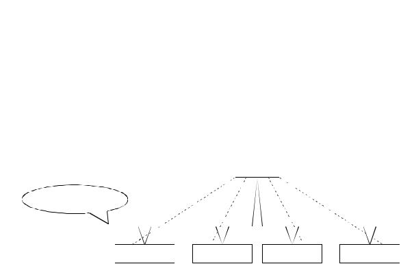
(6) Selection is available from four types of I/O communication methods when this |
|
||||||||||||||
|
module functions as a master node in DeviceNet. They are polling, bit strobe, |
|
||||||||||||||
|
change-of-state and cyclic which are defined in DeviceNet. |
|
|
|
|
|
|
|||||||||
|
However, only one type of communication method can be selected for each slave |
|
||||||||||||||
|
node. |
|
|
|
|
|
|
|
|
|
|
|
|
|
||
|
|
|
|
|
|
QJ71DN91 |
|
|
|
|
|
|
||||
|
|
|
|
Polling |
|
|
|
Change-of-state |
|
|||||||
|
|
|
|
|
|
|
|
|
|
|
||||||
|
DeviceNet network |
|
|
|
|
|
|
|
|
|
|
|
|
|
||
|
|
|
|
Bit strobe |
|
|
|
Cyclic |
|
|
|
|
|
|
||
|
|
|
|
|
|
|
|
|
|
|
|
|
|
|
|
|
|
Slave node 1 |
Slave node 2 |
|
Slave node 3 |
Slave node 4 |
|
||||||||||
For I/O communication, see Section 3.2.1.
(7)When the module functions as a master node of DeviceNet, an I/O communication with input of 256 words (4,096 points) and output of 256 words (4,096 points) can be performed.
(8)When the module functions as a master node of DeviceNet, a message communication of 240 byte data can be performed at one time.
(9)When the module functions as a slave node of DeviceNet, I/O communication with input of 64 words (1,024 points) and output of 64 words (1,024 points) can be performed.
(10)When the module functions as a slave node of DeviceNet, I/O communication can be performed via polling.
1 - 2 |
1 - 2 |
2 SYSTEM CONFIGURATION
MELSEC-Q
2 SYSTEM CONFIGURATION
This chapter explains the system configuration of DeviceNet.
|
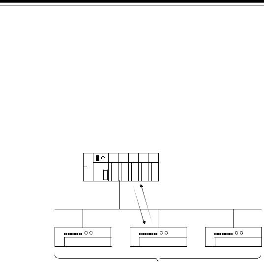
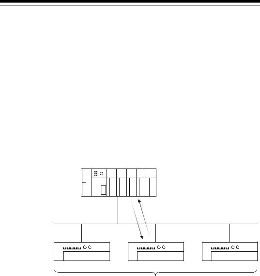
2.1 Overall Configuration |
|
||||||||||||||||||
2 |
|
|
|
|
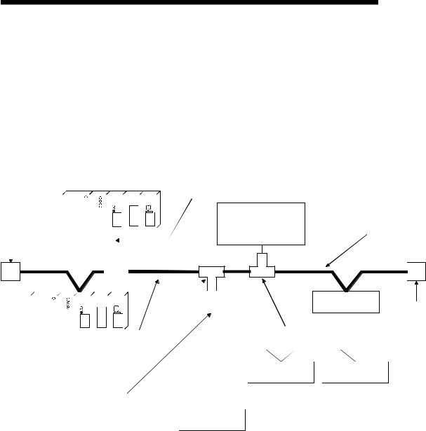
A total of 64 modules including a master node, slave nodes and a master/slave node |
|||||||||||||||
|
|
|
|
|
can be connected. |
|
||||||||||||||
|
|
|
|
|||||||||||||||||
|
|
|
|
|
Each node is connected via a tap from the trunk line or directly to the trunk line. |
|||||||||||||||
|
|
|
|
|
The following shows an example of a system configuration: |
|||||||||||||||
|
|
|
Master node |
|
||||||||||||||||
|
|
|
|
|
|
|
|
|
|
|
|
|
|
|
|
|
|
|
Drop line |
|
|
|
|
|
|
|
|
|
|
|
|
|
|
|
|
|
|
|
|
||
|
Terminal resistor |
|
|
|
|
|
|
|
|
|
|
|
|
|
|
|
|
Network power-supply |
|
|
|
|
|
|
|
|
|
|
|
|
|
|
|
|
|
|
|
|
|||
|
|
|
|
|
|
|
|
|
|
|
|
|
|
|
|
|
|
|||
|
|
|
|
|
|
|
|
|
|
|
|
|
|
|
|
|
||||
|
|
|
|
|
|
|
|
|
|
|
|
|
|
|
|
|
module (24V DC) |
Trunk line (main line) |
||
|
|
|
|
|
|
|
|
|
|
|
|
|
|
|
|
|||||
|
|
|
|
|
|
|
|
|
|
|
|
|
|
|
|
|||||
|
(121Ω , 1/4W) |
|
|
|
|
|
|
|
|
|
|
|
|
|
|
|
|
|
|
|
|
|
|
|
|
|
|
|
|
|
|
|
|
|
|
|
|
|
|
||
|
|
|
|
|
|
|
|
|
|
|
|
|
|
|
|
|
|
|
|
|
|
|
|
|
|
|
|
|
|
|
|
|
|
|
|
|
|
|
|
|
|
|
|
|
|
|
|
|
|
|
|
|
|
|
|
|
|
|
|
|
|
|
|
|
|
|
|
|
|
|
|
|
|
|
|
|
|
|
|
|
|
|
|
Slave node
|
|
|
|
|
|
|
|
|
|
|
|
|
|
|
|
|
|
|
|
Slave node |
Terminal resistor |
|
|
|
|
|
|
|
|
|
|
|
|
|
|
|
|
|
|
|
|
|
|||
|
|
|
|
|
|
|
|
|
|
|
|
|
|
|
|
|
|
|
|
|
|
|
|
|
|
|
|
|
|
|
|
|
|
|
|
|
|
|
|
|
|
|
|
|
|
|
|
|
|
|
|
|
|
|
|
|
|
Tap |
|
|
|
|
|
Power supply tap |
|
|
(121Ω , 1/4W) |
|
|
|
|
|
|
|
|
|
|
|
|
|
|
|
|
|
|
|
|
||||
|
|
|
|
|
|
|
|
|
|
|
|
|
|
|
|
|
|
|
||||
|
|
|
|
|
|
|
|
|
|
|
|
|
|
|
|
|
|
|
|
|||
|
|
|
|
|
|
|
|
|
|
|
|
|
|
|
|
|
|
|
|
|||
|
|
|
|
|
|
|
|
|
|
|
|
|
|
|
|
|
|
|
|
|||
|
|
|
|
|
|
|
|
|
|
|
|
|
|
|
|
|
|
|
|
|||
|
|
|
|
|
|
|
|
|
|
|
|
|
|
|
|
|
|
|
|
|
|
|
|
|
|
|
|
|
|
|
|
|
|
|
|
|
|
|
|
|
|
|
|
|
|
|
|
|
|
|
|
|
|
|
|
|
|
|
|
|
|
|
Slave node |
Slave node |
|
|||
|
|
|
|
|
|
|
|
|
|
|
|
|
|
|
|
|
|
|||||
|
|
|
|
|
|
|
|
|
|
|
|
|
|
|
|
|
|
|||||
|
|
|
Drop line (branch line) |
|
|
|
|
|
|
|
|
|
|
|||||||||
|
|
|
|
|
|
|
|
|
|
|
|
|
|
|
|
|
|
|
|
|
|
|
|
|
|
|
|
|
|
|
|
|
|
|
|
Slave node |
|
|
|
||||||
1)The QJ71DN91 can be used as a master node, a slave node or a master/slave node.
2)A combined maximum of 64 master node and slave nodes can be connected.
3)There is no need to connect the master node and slave nodes in the order of node number.
4)The network cable consists of trunk line (main line) and drop lines (branch lines).
Terminal resistors are required on both sides of the trunk line.
5)It is necessary to connect the network power supply in order to supply the power supply to the communication circuit in addition to the operating power supply of each node.
6)Use the terminal resistors included in the package, or they must be furnished by the user.
2 - 1 |
2 - 1 |

2SYSTEM CONFIGURATION
(1)Network specification
MELSEC-Q
The following explains the network specifications of DeviceNet that uses the QJ71DN91.
(a)Communication speed
The communication speed can be selected from 125kbaud, 250kbaud, or 500kbaud using the mode switch of the QJ71DN91.
The maximum cable length varies depending on the communication speed. 2 See Section 3.1, "Performance Specifications" for details.
(b)Supplying power to the network
The following describes the method of supplying network power to each node:
1)Connect a dedicated power supply tap to the trunk-line cable and install the network power-supply module.
2)The power is supplied from the network power-supply module to each node via the network cable.
Remarks
Inquire to ODVA about the following devices required to construct a DeviceNet network.
•Network power-supply module
•Power supply tap
•Tap
•Terminal resistor
•Network cable
Contact at ODVA is as follows:
Open DeviceNet Vendor Association, Inc. Address
20423 State Road 7 - Suite 499 - Boca Raton, FL 33498 U.S.A. TEL. +1-954-340-5412
FAX. +1-954-340-5413 or +1-561-477-6621
2 - 2 |
2 - 2 |

2 SYSTEM CONFIGURATION
2.2 Applicable Systems
MELSEC-Q
This section describes the system configuration for the QJ71DN91.
(1) Applicable module and the number of modules that can be installed
The following are the CPU module in which the QJ71DN91 can be installed and the number of modules that can be installed.
|
Applicable module |
Number of modules that |
Remarks |
||
|
can be installed |
||||
|
|
|
|
|
|
|
|
Q00JCPU |
Maximum 16 |
( |
1) |
|
|
Q00CPU |
Maximum 24 |
||
|
|
Q01CPU |
|
|
|
|
|
|
|
|
|
|
|
Q02CPU |
|
|
|
CPU module |
|
Q02HCPU |
|
Can be installed in Q mode only |
|
|
Q06HCPU |
Maximum 64 |
|||
|
|
( 1) |
|
||
|
|
Q12HCPU |
|
|
|
|
|
Q25HCPU |
|
|
|
|
|
Q12PHCPU |
Maximum 64 |
( |
1) |
|
|
Q25PHCPU |
|
|
|
 1 See User's Manual (Function Explanation, Program Fundamentals) for the CPU module to use.
(2) Base unit in which the conversion module can be installed
The QJ71DN91 can be installed in any I/O slot ( 2) of the base unit. However, a power shortage may occur depending on the combination with other installed modules and the number of modules used, so always take into consideration the power supply capacity when installing modules.
 2 Limited to the range of the number of I/O points in the CPU module.
(3) Compatibility with a multiple PLC system
First read the QCPU (Q mode) (Function Explanation, Program Fundamentals) User's Manual if the QJ71DN91 is used with a multiple PLC system.
(a)Compatible QJ71DN91
Use a QJ71DN91 with function version B or higher if using the module in a multiple PLC system.
(b)Intelligent function module parameters
Perform PLC write of the intelligent function module parameters to the control PLC of the QJ71DN91 only.
2 - 3 |
2 - 3 |

2SYSTEM CONFIGURATION
(4)Software packages supported
MELSEC-Q
Correspondence between systems which use QJ71DN91s and software packages are as shown below.
The GX Developer is necessary when using a QJ71DN91.
|
|
Software Version |
||
|
|
GX Developer |
GX Configurator-DN 2 |
|
Q00J/Q00/ |
Single PLC system |
Version 7 or later |
Version 1.10L or later |
|
|
|
|||
Q01CPU |
Multiple PLC system |
Version 8 or later |
||
|
||||
|
|
|||
|
|
|
|
|
Q02/Q02H/ |
Single PLC system |
Version 4 or later |
Version 1.00A or later |
|
Q06H/Q12H/ |
|
|
|
|
|
|
|
||
Q25HCPU |
Multiple PLC system |
Version 6 or later |
Version 1.10B or later |
|
|
|
|
|
|
Q12PH/ |
Single PLC system |
Version 7.10L or later |
Version 1.13P or later |
|
|
||||
Q25PHCPU |
Multiple PLC system |
|||
|
|
|||
|
|
|
||
|
|
|
|
|
 2 Version 1.14Q or earlier is incompatible with Each Node Communication Error Status (addresses 1C0H to 1C3H/448 to 451). Use the product of Version 1.15R or later.
(5) Precautions on wiring
In order to avoid the effects of noise, the DeviceNet communication cable, power cable and signal lines for the I/O module should be installed in such a way that they are sufficiently away from each other.
(6) Remote operation is not allowed from other DeviceNet node
Each DeviceNet node on DeviceNet cannot read/write/monitor the sequence program or data of the PLC CPU where the QJ71DN91 is installed.
2.3 How to Check the Function Version, Serial No. and Software Version
This section describes how to check the function version and serial No. of the
QJ71DN91 and the GX Configurator-DN software version.
(1)How to check the function version and serial No. of the QJ71DN91
(a)To check the version using the "SERIAL column of the rating plate" located on the side of the module
Serial No. (first 5 digits)
 Function version
03052


(b)To check the version using the GX Developer See Section 9.3 of this manual.
2 - 4 |
2 - 4 |
2 SYSTEM CONFIGURATION
MELSEC-Q
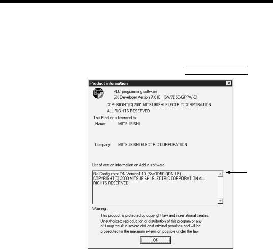
(2) How to check the GX Configuration-DN software version
The GX Configurator-DN software version can be checked in GX Developer's
"Product information" screen.
[Startup procedure]
GX Developer  "Help"
 Product information
Software version
(In the case of GX Developer Version 7)
2.4 About Use of the QJ71DN91 with the Q00J/Q00/Q01CPU
Here, use of the QJ71DN91 with the Q00J/Q00/Q01CPU is explained.
(1)Number of QJ71DN91 that can be installed when the Q00J/Q00/
Q01CPU is used.
See item 2.2 concerning the number of QJ71DN91 that can be installed when the
Q00J/Q00/Q01CPU is used.
(2) Limitations when using the Q00J/Q00/Q01CPU
When using Q00J/Q00/Q01CPU, use QJ71DN91 which function version is B and first 5 digits of the serial No. is 03052 or later.
2 - 5 |
2 - 5 |

2 SYSTEM CONFIGURATION
MELSEC-Q
2.5 About Additional Function
The added function is described below.
Function |
Serial No. |
Function Outline |
Reference Section |
Addition of Each Node Communication |
First five digits of |
Indicates whether an I/O |
|
Error Status (addresses 01C0H to 01C3H |
serial No. are |
communication error has |
Section 3.4.1 (10) |
/448 to 451) |
04102 or later |
occurred or not in each node. |
|
POINT
Refer to Section 2.3 for the way to confirm the serial No.
2.6 Compatible DeviceNet Products from Other Manufacturers
It is assumed that most of the DeviceNet products on the market are compatible.
However, compatibility with the products of other manufacturers is not guaranteed.
2 - 6 |
2 - 6 |

3 SPECIFICATIONS
MELSEC-Q
3 SPECIFICATIONS
3.1 Performance Specifications
This section explains the performance specifications for QJ71DN91, I/O signals for
PLC CPU and specifications for buffer memory.
See the PLC CPU User's Manual to be used for the general specifications for
QJ71DN91.
|
|
|
|
Item |
|
|
|
|
Specifications |
|
|
||
|
|
|
|
Node type |
|
|
Device net master (Group 2 only client) |
|
|
||||
|
|
|
|
|
|
|
|
||||||
3 |
|
|
|
Node numbers which can be set |
0 to 63 |
|
|
|
|
|
|||
|
|
|
Number of |
|
Message connection |
63 |
|
|
|
|
|
||
|
|
|
When |
connections |
|
|
|
|
|
|
|||
|
|
|
that be |
|
I/O connection |
63 (polling, bit strobe, change of state, cyclic) |
|
|
|||||
|
|
|
|
|
|
||||||||
|
|
|
master |
created |
|
|
|
||||||
|
|
|
|
|
|
|
|
|
|
|
|
||
|
|
|
|
|
I/O |
Send |
Max. 4096 points (512 bytes), max. 256 bytes per 1 node |
|
|||||
|
|
|
function |
|
|
|
|||||||
|
|
|
Amount of |
|
communica- |
|
|||||||
|
|
|
|
|
Receive |
Max. 4096 points (512 bytes), max. 256 bytes per 1 node |
|
||||||
|
|
|
|
|
tion |
|
|||||||
|
|
|
|
communica- |
|
|
|||||||
|
|
|
|
|
Message |
Send |
Max. 240 bytes |
|
|
|
|
||
|
|
|
|
tion data |
|
communica- |
|
|
|
|
|||
|
|
|
|
|
Receive |
Max. 240 bytes |
|
|
|
|
|||
|
|
specifications |
|
|
|
tion |
|
|
|
|
|||
|
|
|
Node type |
|
|
Device net slaves (Group 2 server) |
|
|
|
||||
|
|
|
Setting possible node number |
0 to 63 |
|
|
|
|
|
||||
|
|
|
Number of |
|
|
|
|
|
|
|
|
|
|
|
|
When slave |
connections |
|
I/O connection |
1 (polling) |
|
|
|
|
|
||
|
|
Communication |
function |
that can be |
|
|
|
|
|
|
|
|
|
|
|
created |
|
|
|
|
|
|
|
|
|
||
|
|
|
|
|
|
|
|
|
|
|
|
||
|
|
|
Amount of |
|
I/O |
Send |
Max. 1024 points (128 bytes) |
|
|
|
|||
|
|
|
communica- |
communica- |
|
|
|
||||||
|
|
|
Receive |
Max. 1024 points (128 bytes) |
|
|
|
||||||
|
|
|
tion data |
|
tion |
|
|
|
|||||
|
|
Communications speed |
|
|
One speed can be selected from 125 kbps, 250 kbps and 500kbps. |
||||||||
|
|
|
|
|
|||||||||
|
|
|
|
|
|
|
|
|
Maximum transmitting distance of |
Length of drop line |
|||
|
|
|
|
|
|
|
|
Communic |
|
trunk line |
|
||
|
|
|
|
|
|
|
|
|
|
|
|
||
|
|
|
|
|
|
|
|
ations |
Thick |
Thin |
Thick and |
|
|
|
|
|
|
|
|
|
|
speed |
thin cables |
Maximum |
Total |
||
|
|
|
Maximum cable length |
|
|
Cables |
Cables |
||||||
|
|
|
|
|
|
coexist |
|
|
|||||
|
|
|
|
|
|
|
|
|
|
|
|
|
|
|
|
|
|
|
|
|
|
125 kbaud |
500 m |
|
|
|
156 m |
|
|
|
|
|
|
|
|
250 kbaud |
250 m |
100 m |
See 3.1.1 |
6 m |
78 m |
|
|
|
|
|
|
|
|
500 kbaud |
100 m |
|
|
|
39 m |
|
|
|
Current consumption required on the network |
0.03 A |
|
|
|
|
|
||||
|
|
Number of times to write flash ROM |
|
|
Max. 100000 times |
|
|
|
|
||||
|
|
No. of I/O occupied points |
|
|
32 points (I/O allocation: Intelligent 32 points) |
|
|
||||||
|
|
5 V DC internal current consumption |
|
|
0.17 A |
|
|
|
|
|
|||
|
|
Weight |
|
|
|
|
|
0.11 kg |
|
|
|
|
|
 : The maximum cable length complies with that in the device net specification (Release 2.0) Volumes 1 and 2.
3.1.1 Maximum transmitting distance when thick and thin cables coexist
The table below lists both the maximum transmitting distance when thick and thin cables coexist.
Communication speed |
Maximum transmitting distance of trunk line when thick |
|
and thin cables coexist |
||
|
||
125 kbaud |
Thick cable length + 5 Thin Cable length < 500 m |
|
250 kbaud |
Thick cable length +2.5 Thin cable length < 250 m |
|
500 kbaud |
Thick cable length + Thin cable length < 100 m |
3 - 1 |
3 - 1 |

3 SPECIFICATIONS
3.2 Functions
This section explains the functions of the QJ71DN91.
MELSEC-Q
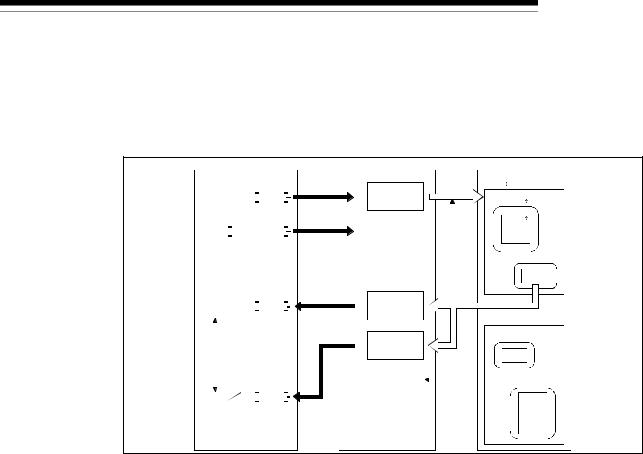
3.2.1 Master function (I/O communication function)
The I/O communication function executes the I/O data communication with each slave |
|||||
node. |
|
|
|
|
|
In the I/O communication function, the connection type can be set according to the |
|||||
specification of the slave node. |
|
|
|
|
|
There are four connection types: polling, bit strobe, change-of-state, and cyclic. The |
|
||||
|
|||||
connection type can be set with a parameter. |
|
|
3 |
||
(1) When GX Configurator-DN is used |
|
||||
|
|
|
|||
|
The following explains the I/O communication function when the GX |
|
|||
|
Configurator-DN is used. |
|
|
|
|
|
|
|
|
|
|
|
PLC CPU |
QJ71DN91 |
Slave node |
||
|
SET Y11 |
|
|
1) |
I/O communication |
|
|
|
|
|
|
|
|||
3) |
request |
2) |
|||||
0700H |
|||||||
|
X |
|
|
|
|||
|
|
Master function |
|
||||
|
|
|
|
|
receive |
Transmission |
|
|
|
|
|
|
data area |
|
|
|
|
|
|
|
07FFH |
|
|
|
|
4) |
0900H |
5) |
|||
|
Y |
||||||
|
|
Master function |
|
||||
|
|
|
|||||
|
|
|
|
|
transmit |
Reception |
|
|
|
|
|
|
data area |
|
|
|
|
|
|
|
09FFH |
|
|
[I/O communication]
1)When the I/O communication request (Y11) is set, the I/O communication with each slave node starts. It is not necessary to set Y11, however, when the auto communication start is set with a parameter.
[Reception data]
2)The input status from each slave node is automatically stored in the "master function reception data" area of the buffer memory in the QJ71DN91.
3)The input status stored in the "master function reception data" area of the buffer memory is loaded onto the PLC CPU by the auto refresh setting.
[Transmission data]
4)The ON/OFF information to be sent to the slave node is written into the "master function transmission data" area of the buffer memory by the auto refresh setting.
5)The ON/OFF information stored in the "master function transmission data" area is automatically sent to a slave node.
3 - 2 |
3 - 2 |
3 SPECIFICATIONS
MELSEC-Q
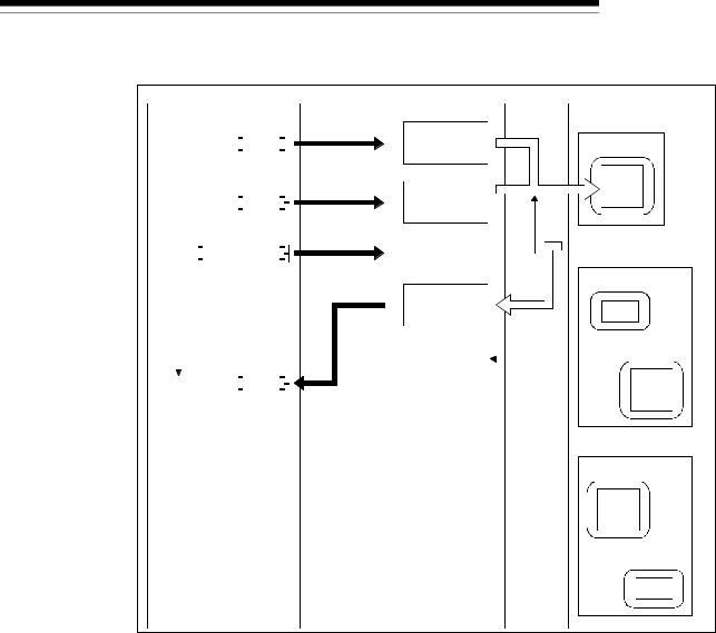
(2)When the sequence program is used
The following explains the I/O communication function when the sequence program is used.
PLC CPU |
QJ71DN91 |
Slave node |
1)I/O communication
|
|
|
|
|
|
SET Y11 |
|
|
|
|
request |
|
|||
|
|
|
|
|
|||||||||||
|
|
|
|
||||||||||||
|
|
|
|
|
|
|
|
|
|
|
|
|
|
|
|
|
|
|
3) |
0700H |
2) |
||||||||||
|
|
|
|
|
|
|
|
FROM |
|
|
|
|
Master function |
|
|
|
|
|
|
|
|
|
|
|
|||||||
|
|
X01 |
|
|
|
receive |
Transmission |
||||||||
I/O communication |
data area |
|
|||||||||||||
in progress |
07FFH |
|
|||||||||||||
|
|
|
|
|
|
|
TO |
|
|
|
4) |
0900H |
3) |
||
|
|
|
|
|
|
|
|
|
|
|
|||||
|
|
|
|
|
|
|
|
|
|
|
|||||
|
|
|
|
|
|
|
|
||||||||
|
|
|
|
||||||||||||
|
|
|
|
|
|
|
|
|
|
|
|
Master function |
|
||
X01 |
|
||||||||||||||
|
transmit |
Reception |
|||||||||||||
I/O communicating |
|
||||||||||||||
data area |
|
||||||||||||||
|
|
|
|
|
|
|
|
|
|
|
|
|
09FFH |
|
|
[I/O communication]
1)When the I/O communication request (Y11) is set, the I/O communication with each slave node starts. It is not necessary to set Y11, however, when the auto communication start is set with a parameter.
[Reception data]
2)The input status from each slave node is automatically stored in the "master function receive data" area of the buffer memory in the QJ71DN91.
3)The input status stored in the "master function receive data" area of the buffer memory is loaded onto the PLC CPU by the FROM instruction of the sequence program.
[Transmission data]
4)The ON/OFF information to be sent to the slave node is written into the "master function transmit data" area of the buffer memory by the TO instruction of the sequence program.
5)The ON/OFF information stored in the "master function transmit data" area is automatically sent to the slave node.
3 - 3 |
3 - 3 |

3 SPECIFICATIONS
MELSEC-Q
(3) Overview of each connection type
The following explains an overview of each connection type used during the I/O communication.
(a) Polling
As shown in the following diagram, the communication method by which the communication with each slave node is repeated, as described from 1) to 6), is the polling communication. The connection that uses this communication is the polling connection.
1)The master node transmits the output data.
2)The slave node transmits input data by setting 1) to trigger.
3)The master node transmits the output data.
4)The slave node transmits input data by setting 3) to trigger.
5)The master node transmits the output data.
6)The slave node transmits input data by setting 5) to trigger.
Master node
1)
4) |
6) |
3) |
5) |
2) |
|
Slave node
3 - 4 |
3 - 4 |

3 SPECIFICATIONS
MELSEC-Q
(b) Bit strobe
As shown in the following diagram, the communication method by which the communication with each slave node is repeated, as described from 1) to 4), is the bit strobe communication. The connection that uses this communication is the bit strobe connection.
1)Output information of a maximum of one bit is transmitted simultaneously to each slave node.
2)The slave node transmits the input data by setting the transmission of
1)to trigger.
3)The slave node transmits the input data by setting the transmission of
1)to trigger.
4)The slave node transmits the input data by setting the transmission of
1)to trigger.
Master node
4)
2) |
1) |
3) |
|
|
|||||||||||||||||
|
|
|
|
|
|
|
|
|
|
|
|||||||||||
|
|
|
|
|
|
|
|
|
|
|
|
|
|
|
|
|
|
|
|
|
|
|
|
|
|
|
|
|
|
|
|
|
|
|
|
|
|
|
|
|
|
|
|
|
|
|
|
|
|
|
|
|
|
|
|
|
|
|
|
|
|
|
|
|
|
Slave node
3 - 5 |
3 - 5 |
3 SPECIFICATIONS
MELSEC-Q
(c) Change-of-state
As shown in the following diagram, the communication method that executes the communication of [1] and [2] as the I/O data changes is the change-of-state communication, and the connection that uses this communication is the change-of-state connection.
No data transmission is performed unless the I/O data is changed.
1)When the output data of the master node changes, the data is sent to the slave node.
2)When the input data of the slave node changes, the data is sent to the master node.
There is no concept of the network scan in the change-of-state communication.
Master node
1)2)
Slave node
3 - 6 |
3 - 6 |
3 SPECIFICATIONS
MELSEC-Q
(d) Cyclic
As shown in the following diagram, the communication method that regularly repeats the communication of [1] and [2] is the cyclic communication, and the connection that uses this communication is the cyclic connection.
1)The data of the master node is sent to the slave node.
2)The data of the slave node is sent to the master node.
The cycle of the cyclic communication can be specified for each slave node.
Specify the cycle of the cyclic communication in the following parameter items:
Transmission cycle from master node: Production inhibit time Transmission cycle from slave node: Expected packet rate
There is no concept of the network scan in the cyclic communication.
Master node
1)2)
Slave node
3 - 7 |
3 - 7 |
3 SPECIFICATIONS
3.2.2 Master function (Message communication function)
MELSEC-Q
The message communication function is used to get and set the attribute data of a slave node.
(1) Getting attributes
|
|
PLC CPU |
|
|
QJ71DN91 |
|
|
Slave node (MAC ID) |
|||||||||||||||
|
|
|
|
|
|
|
|
|
|
1) |
|
0110H |
Message |
2) |
Class |
||||||||
|
|
|
|
|
|
|
TO |
|
|
|
|
|
|
|
communication |
|
|
Instance |
|||||
|
|
|
|
|
|
|
|
|
|
|
|||||||||||||
|
|
|
|
|
|
|
|
|
|
|
|
|
011FH command area |
|
|
||||||||
|
|
|
|
|
|
|
|
|
|
|
|
|
|
|
|
|
|
|
|
||||
|
|
|
|
|
|
|
|
|
|
2) |
|
|
Message |
|
|
|
Attribute |
||||||
|
|
|
|
|
SET |
Y12 |
|
|
|
|
|
|
communication |
|
|
|
|
|
|
|
|||
|
|
|
|
|
|
|
|
|
|
|
|
|
|
request |
|
|
|
Attribute |
|||||
|
|
|
|
|
|
|
|
|
|
|
|
|
|
|
|
|
|
|
|
Instance |
|||
|
|
|
|
|
|
|
|
|
|
|
|
|
|
|
|
|
|
|
|
|
Attribute |
||
|
|
|
|
|
|
|
|
|
|
6) |
|
0120H |
Message |
3) |
|
|
|
|
|
||||
|
|
|
|
|
|
|
|
|
|
|
|
|
|
|
|
||||||||
|
|
|
|
|
|
|
FROM |
|
|
|
|
|
|
|
communication |
|
|
|
|
|
|
|
|
|
|
|
|
|
|
|
|
|
|
|
|
|
|
|
|
|
|||||||
|
|
|
|
|
|
|
|
|
|
|
|
|
|
|
|
||||||||
|
|
X02 X05 |
|
|
|
|
|
|
012FH |
result area |
|
|
Class |
||||||||||
|
|
|
|
|
|
|
|
|
|
|
|
|
|
|
|
|
|||||||
|
|
|
|
|
|
|
|
|
|
|
|
|
0130H |
Message |
|
|
Instance |
||||||
|
|
|
|
|
|
|
|
|
|
|
|
|
|
|
|
|
|||||||
|
|
|
|
|
|
|
|
|
|
|
|
|
|
|
communication |
|
|
|
|
|
|
|
|
|
|
|
|
|
|
|
|
|
|
|
|
|
01A7H |
data area |
|
|
|
Attribute |
|||||
|
|
|
|
|
|
|
|
|
|
|
|
|
|
|
|
|
|
|
|
|
|
||
|
|
|
|
|
|
|
4) |
|
|
Message |
|
|
|
|
|
|
|
||||||
|
|
|
|
|
|
|
|
|
|
|
|
|
|
|
communication |
|
|
|
|
Instance |
|||
|
|
|
|
|
|
|
|
|
|
|
|
|
|
|
|
|
|
||||||
|
|
|
|
|
|
|
FROM |
|
|
|
|
|
|
|
complete |
|
|
|
|
Attribute |
|||
|
|
|
|
|
|
|
|
|
|
|
|
|
|
|
|
|
|
||||||
|
|
|
|
|
|
|
|
|
|
|
|
|
|
|
|
|
|
|
|
||||
|
X02 X05 |
|
|
|
5) |
|
|
|
|
|
|
|
|
|
|
|
|
||||||
Message communication |
|
|
|
|
|
|
|
|
Attribute |
|
|||||||||||||
completion |
|
|
|
|
|
|
|
|
|
|
|
|
|
|
Attribute |
||||||||
 : In DeviceNet, the area used for reading and writing via communication is specified by the numbers representing the class ID, instance ID, and attribute ID. For details, refer to the manual of each slave node.
1)The TO instruction of the sequence program sets to get attributes in the "message communication command" area of the buffer memory.
2)When the message communication request (Y12) is turned ON by the sequence program, the data, which is set in the "message communication command" area in the buffer memory, is sent to the slave node and the message communication starts.
3)When the QJ71DN91 receives data from the slave node, it is processed as follows:
•The specific data of the slave node that is set in the "message communication command" area is stored in the "message communication data" area of the buffer memory.
•The processing result of message communication is stored in the "message communication result" area of the buffer memory.
4)The message communication is completed when the processing result is stored in the "message communication result" area of the buffer memory, and the message communication completion (X02) is automatically turned ON.
5)Upon normal completion, the data in the slave node, which is stored in the "message communication data" area of the buffer memory, is loaded onto the PLC CPU by the FROM instruction of the sequence program.
6)If the message communication error signal (X05) is turned ON, the FROM instruction reads the contents of the "message communication result" area, and the cause of the error is verified.
3 - 8 |
3 - 8 |
3SPECIFICATIONS
(2)Setting attributes
MELSEC-Q
PLC CPU |
|
QJ71DN91 |
|
Slave node (MAC ID) |
||||||
|
|
|
|
1) |
0110H |
Message |
3) |
Class |
||
|
TO |
|
|
|
|
communication |
|
Instance |
||
|
|
|
|
|||||||
|
|
|
|
|
011FH command area |
|
||||
|
|
|
|
|
|
|
Attribute |
|||
|
|
|
|
|
0130H |
|
|
|
||
2) |
Message |
|
|
|
|
|||||
|
|
Attribute |
||||||||
|
|
|
||||||||
|
TO |
|
|
|
|
communication |
|
|
||
|
|
|
|
|
|
|
|
|
||
|
|
|
|
|
01A7H |
data area |
|
|
|
|
|
|
|
|
|
|
|
|
|
|
|
3)Message
|
|
|
|
SET Y12 |
|
|
|
communication |
|
|
Class |
|||||
|
|
|
|
|
|
|
|
|||||||||
|
|
|
|
|
|
|
|
|
|
request |
|
|
||||
|
|
|
|
|
|
|
|
|
|
|
|
|
|
|||
|
|
|
|
|
|
|
|
|
0120H |
Message |
4) |
|
Instance |
|||
|
|
|
|
|
|
|
|
|
|
|
|
|
|
|||
|
|
|
|
|
|
|
|
|
|
|
communication |
|
|
Attribute |
||
|
|
|
|
|
|
|
|
|
|
|
result area |
|
|
|||
|
|
|
|
|
|
|
|
|
012FH |
|
|
|
|
|||
|
|
|
|
|
|
|
|
|
|
|
|
|
|
|
||
|
|
|
|
|
|
|
5) |
|
Message |
|
|
Instance |
||||
|
|
|
|
|
|
|
|
communication |
|
|
|
|||||
|
|
|
|
|
|
Next |
|
|
|
complete |
|
|
|
Attribute |
||
|
|
|
|
|
|
|
|
|
|
|
|
|||||
|
|
|
|
|
|
processing |
|
|
|
|
|
|
|
|
|
|
|
X02 X05 |
|
6) |
|
|
|
|
|
|
|
Attribute |
|||||
Message |
|
|
|
communication |
|
|
|
completion |
Class |
||
|
|||
|
Instance |
||
|
|
Attribute |
|
|
|
|
|
|
|
Attribute |
|
|
|
Instance |
|
|
|
Attribute |
|
1)The TO instruction of the sequence program sets to set attributes in the "message communication command" area of the buffer memory.
2)The TO instruction of the sequence program writes the data to be written in the "message communication data" area of the buffer memory.
3)When the message communication request (Y12) is turned ON, the data, which is stored in the "message communication data" area of the buffer memory, is written to the slave node in the area specified by the "message communication command."
4)When the write process is finished, the message communication result is stored in the "message communication result" area of the buffer memory.
5)The message communication is completed when the processing result is stored in the "message communication result" area of the buffer memory, and the message communication completion (X02) is automatically turned ON.
6)If the message communication error signal (X05) is turned ON, the FROM instruction reads the contents of the "message communication result" area, and the cause of the error is verified.
3 - 9 |
3 - 9 |

3SPECIFICATIONS
(3)Reading the communication error information
MELSEC-Q
|
|
|
PLC CPU |
|
|
QJ71DN91 |
|
|
Slave node (MAC ID) |
||||||||||||||||
|
|
|
|
|
|
|
|
|
|
|
|
|
0110H |
|
|
|
|
I/O |
Class 1 |
||||||
|
|
|
|
|
|
|
|
|
|
1) |
|
Message |
communication |
||||||||||||
|
|
|
|
|
|
|
|
|
|
|
|
|
|
|
|
|
|
||||||||
|
|
|
|
|
|
|
TO |
|
|
|
|
|
|
|
|
communication |
|
|
Instance |
||||||
|
|
|
|
|
|
|
|
|
|
|
|
|
|||||||||||||
|
|
|
|
|
|
|
|
|
|
|
|
|
|
||||||||||||
|
|
|
|
|
|
|
|
|
|
|
|
|
011FH command area |
|
|
||||||||||
|
|
|
|
|
|
|
|
|
|
|
|
|
|
|
|
Attribute |
|
||||||||
|
|
|
|
|
|
|
|
|
|
2) |
|
|
Message |
|
|
|
|||||||||
|
|
|
|
SET |
Y12 |
|
|
|
|
|
|
communication |
|
|
|
Attribute |
|||||||||
|
|
|
|
|
|||||||||||||||||||||
|
|
|
|
|
|
|
|
|
|
|
|
|
|
request |
|
|
|
|
|
Instance |
|||||
|
|
|
|
|
|
|
|
|
|
|
|
|
|
|
|
|
|
||||||||
|
|
|
|
|
|
|
|
|
|
|
|
|
|
|
|
|
|
|
|
|
|
||||
|
|
|
|
|
|
|
|
|
|
|
|
|
|
|
|
Slave |
2) |
|
|
||||||
|
|
|
|
|
|
|
|
|
|
|
|
|
|
|
|
information |
|
|
|
|
Attribute |
|
|||
|
|
|
|
|
|
|
|
|
|
|
|
|
|
|
|
|
|
|
|
||||||
|
|
|
|
|
|
|
|
|
|
|
|
|
|
|
|
storage area |
|
|
|
|
|||||
|
|
|
|
|
|
|
|
|
|
|
|
|
0120H |
|
|
|
|
|
|
|
|
Attribute |
|||
|
|
|
|
|
|
|
|
|
|
5) |
|
|
Message |
|
|
|
|
|
|
|
|||||
|
|
|
|
|
|
|
|
|
|
|
|
|
|
|
|
Attribute |
|||||||||
|
|
|
|
|
|
|
|
|
|
|
|
|
|
|
|||||||||||
|
|
|
|
|
|
|
FROM |
|
|
|
|
|
|
|
|
communication |
|
|
|
|
|||||
|
X02 X05 |
|
|
|
|
|
|
|
012FH |
|
result area |
|
|
|
|
|
|
|
|||||||
|
|
|
|
|
|
|
|
|
|
|
|
|
|
|
|
|
|
|
|
|
|
|
|
||
|
|
|
|
|
|
|
|
|
|
|
|
|
0130H |
|
Message |
|
|
|
|
|
|
|
|||
|
|
|
|
|
|
|
|
|
|
|
|
|
|
|
|
|
|
Class |
|||||||
|
|
|
|
|
|
|
|
|
|
|
|
|
|
|
|
communication |
|
|
|||||||
|
|
|
|
|
|
|
|
|
|
|
|
|
|
|
|
|
|
||||||||
|
|
|
|
|
|
|
|
|
|
|
|
|
01A7H |
|
data area |
|
|
Instance |
|||||||
|
|
|
|
|
|
|
|
|
|
|
|
|
|
|
|
|
|
|
|||||||
|
|
|
|
|
|
3) |
|
Message |
|
|
|
|
|
||||||||||||
|
|
|
|
|
|
|
|
|
|
Attribute |
|||||||||||||||
|
|
|
|
|
|
|
|
|
|
|
|
|
|
communication |
|
|
|
|
|
|
|
||||
|
|
|
|
|
|
|
|
|
|
|
|
|
|
|
|
|
Attribute |
|
|||||||
|
|
|
|
|
|
|
FROM |
|
|
|
|
|
|
complete |
|
|
|
||||||||
|
|
|
|
|
|
|
|
|
|
|
|
|
|
||||||||||||
|
X02 X05 |
|
4) |
|
|
|
|
|
|
|
|
|
|
Attribute |
|||||||||||
Message communication |
|
|
|
|
|
|
|
|
|
|
|
|
|
||||||||||||
completion |
Instance |
|
|
|
Attribute |
The status of each slave station is stored during I/O communication.
1)The TO instruction of the sequence program sets to read the communication error information in the "message communication command" area of the buffer memory.
2)When the message communication request (Y12) is turned ON by the sequence program, the error information of the applicable slave node that has been accumulated in the QJ71DN91 is read and processed as follows:
•The error information of the slave node that was set by the "message communication command" area is stored in the "message communication data" area of the buffer memory.
•The processing result of the message communication is stored in the "message communication result" area of the buffer memory.
3)When the processing result is stored in the "message communication result" area of the buffer memory, the message communication completion (X02) is automatically turned ON.
4)The communication error information of the slave node, which is stored in the "message communication data" area of the buffer memory, is loaded onto the PLC CPU by the FROM instruction of the sequence program.
5)If the message communication error signal (X05) is turned ON, the FROM instruction reads the contents of the "message communication result" area, and the cause of the error is verified.
3 - 10 |
3 - 10 |
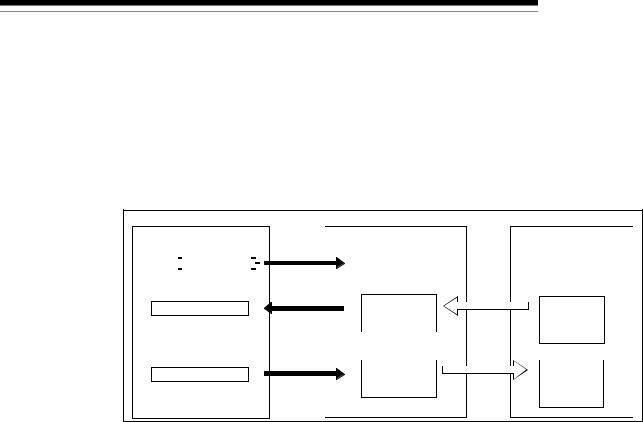
3 SPECIFICATIONS
3.2.3 Slave function (I/O communication function)
MELSEC-Q
The I/O communication function executes the communication of the I/O data with the master node using the polling method.
(1) When GX Configurator-DN is used
The following explains the I/O communication function when the GX Configurator-DN is used.
|
|
PLC CPU |
|
QJ71DN91 |
Master node |
||||
|
|
|
|
|
1) |
|
I/O communication |
|
|
|
|
|
SET Y11 |
|
|
|
|
||
|
|
|
|
|
0B00H |
request |
2) |
||
|
|
|
|
3) |
|||||
|
|
|
Slave function |
||||||
|
|
|
|
||||||
|
|
|
X |
|
|
receive |
Transmission |
||
|
|
|
|
|
|||||
|
|
|
|
|
|
|
0B3FH |
data area |
|
|
|
|
|
|
|
|
|
|
|
|
|
|
|
4) |
0C00H |
Slave function |
5) |
||
|
|
|
|
||||||
|
|
|
|
||||||
|
|
|
Y |
|
|
transmit |
Reception |
||
|
|
|
|
|
|||||
|
|
|
|
|
|
|
0C3FH |
data area |
|
|
|
|
|
|
|
|
|
||
|
|
|
|
|
|
|
|
|
|
[I/O communication]
1)Communication with the master node starts when the I/O communication request (Y11) is turned ON.
[Reception data]
2)Transmission data from the master node is automatically stored in the "slave function receive data" area of the buffer memory in the QJ71DN91.
3)Transmission data from the mater node, which is stored in the "slave function receive data" area of the buffer memory, is loaded onto the PLC CPU by the auto refresh setting.
[Transmission data]
4)With the auto refresh setting, the ON/OFF information to be sent to the master node is written in the "slave function transmit data" area of the buffer memory.
5)The ON/OFF information, which is stored in the "slave function transmit data" area of the buffer memory, is automatically sent to the master node.
3 - 11 |
3 - 11 |

3SPECIFICATIONS
(2)When the sequence program is used
MELSEC-Q
The following explains the I/O communication function when the sequence program is used.
PLC CPU |
QJ71DN91 |
Master node |
1)I/O communication
|
|
|
|
SET Y11 |
|
|
request |
2) |
||||
|
|
|
|
|||||||||
|
|
|
|
|
|
|
|
|
|
|
|
|
|
|
|
|
|
FROM |
|
3) |
0B00H |
Slave function |
|||
|
|
|
|
|
|
|
||||||
|
|
|
|
|
|
|
|
receive |
|
|||
X01 |
|
Transmission |
||||||||||
0B3FH |
data area |
|||||||||||
I/O communicating |
|
|
|
|||||||||
|
|
|
|
|
TO |
|
4) |
0C00H |
Slave function |
5) |
||
|
|
|
|
|
|
|||||||
|
|
|
|
|
|
|
|
transmit |
Reception |
|||
X01 |
0C3FH |
data area |
||||||||||
I/O communicating |
|
|||||||||||
|
|
|
||||||||||
[I/O communication]
1)Communication with the master node starts when the I/O communication request (Y11) is turned ON.
[Reception data]
2)Transmission data from the master node is automatically stored in the "slave function receive data" area of the buffer memory in the QJ71DN91.
3)The transmission data from the master node, which is stored in the "slave function receive data" area of the buffer memory, is loaded onto the PLC CPU by the FROM instruction of the sequence program.
[Transmission data]
4)The TO instruction of the sequence program writes the ON/OFF information to be sent to the master node in the "slave function transmit data" area of the buffer memory.
5)The ON/OFF information, which is stored in the "slave function transmit data" area of the buffer memory, is automatically sent to the master node.
3 - 12 |
3 - 12 |
Loading...