


 Loading...
 SAFETY PRECAUTIONS
(Please read these instructions before using this equipment.)
Before using this product, please read this manual and the relevant manuals introduced in this manual carefully and pay full attention to safety to handle the product correctly.
Refer to the Users manual of the QCPU module to use for a description of the PLC system safety precautions.
In this manual, the safety instructions are ranked as "DANGER" and "CAUTION".

 DANGER

 CAUTION
Indicates that incorrect handling may cause hazardous conditions, resulting in death or severe injury.
Indicates that incorrect handling may cause hazardous conditions, resulting in medium or slight personal injury or physical damage.
Depending on circumstances, procedures indicated by  CAUTION may also be linked to serious results.
In any case, it is important to follow the directions for usage.
Please save this manual to make it accessible when required and always forward it to the end user.
A - 1

For Safe Operations
1. Prevention of electric shocks
 DANGER
 Never open the front case or terminal covers while the power is ON or the unit is running, as this may lead to electric shocks.
 Never run the unit with the front case or terminal cover removed. The high voltage terminal and charged sections will be exposed and may lead to electric shocks.
 Never open the front case or terminal cover at times other than wiring work or periodic inspections even if the power is OFF. The insides of the module and servo amplifier are charged and may lead to electric shocks.
 Completely turn off the externally supplied power used in the system before mounting or removing the module, performing wiring work, or inspections. Failing to do so may lead to electric shocks.
 When performing wiring work or inspections, turn the power OFF, wait at least ten minutes, and then check the voltage with a tester, etc. Failing to do so may lead to electric shocks.
 Be sure to ground the module, servo amplifier and servomotor (Ground resistance : 100
  or less). Do not ground commonly with other devices.
 The wiring work and inspections must be done by a qualified technician.
 Wire the units after installing the module, servo amplifier and servomotor. Failing to do so may lead to electric shocks or damage.
 Never operate the switches with wet hands, as this may lead to electric shocks.
 Do not damage, apply excessive stress, place heavy things on or sandwich the cables, as this may lead to electric shocks.
 Do not touch the module, servo amplifier, servomotor connector or terminal blocks while the power is ON, as this may lead to electric shocks.
 Do not touch the built-in power supply, built-in grounding or signal wires of the module and servo amplifier, as this may lead to electric shocks.
2. For fire prevention
 CAUTION
 Install the module, servo amplifier, servomotor and regenerative resistor on incombustible. Installing them directly or close to combustibles will lead to fire.
 If a fault occurs in the module or servo amplifier, shut the power OFF at the servo amplifier's power source. If a large current continues to flow, fire may occur.
 When using a regenerative resistor, shut the power OFF with an error signal. The regenerative resistor may abnormally overheat due to a fault in the regenerative transistor, etc., and may lead to fire.
 Always take heat measures such as flame proofing for the inside of the control panel where the servo amplifier or regenerative resistor is installed and for the wires used. Failing to do so may lead to fire.
 Do not damage, apply excessive stress, place heavy things on or sandwich the cables, as this may lead to fire.
A - 2

3. For injury prevention
 CAUTION
 Do not apply a voltage other than that specified in the instruction manual on any terminal. Doing so may lead to destruction or damage.
 Do not mistake the terminal connections, as this may lead to destruction or damage.
 Do not mistake the polarity ( + / - ), as this may lead to destruction or damage.
 Do not touch the heat radiating fins of module or servo amplifier, regenerative resistor and servomotor, etc., while the power is ON and for a short time after the power is turned OFF. In this timing, these parts become very hot and may lead to burns.
 Always turn the power OFF before touching the servomotor shaft or coupled machines, as these parts may lead to injuries.
 Do not go near the machine during test operations or during operations such as teaching. Doing so may lead to injuries.
4. Various precautions
Strictly observe the following precautions. Mistaken handling of the unit may lead to faults, injuries or electric shocks.
(1) System structure
 CAUTION
 Always install a leakage breaker on the module and servo amplifier power source.
 If installation of an electromagnetic contactor for power shut off during an error, etc., is specified in the instruction manual for the servo amplifier, etc., always install the electromagnetic contactor.
 Install the emergency stop circuit externally so that the operation can be stopped immediately and the power shut off.
 Use the module, servo amplifier, servomotor and regenerative resistor with the correct combinations listed in the instruction manual. Other combinations may lead to fire or faults.
 Use the CPU module, base unit and positioning module with the correct combinations listed in the instruction manual. Other combinations may lead to faults.
 If safety standards (ex., robot safety rules, etc.,) apply to the system using the module, servo amplifier and servomotor, make sure that the safety standards are satisfied.
 Construct a safety circuit externally of the module or servo amplifier if the abnormal operation of the module or servo amplifier differ from the safety directive operation in the system.
 In systems where coasting of the servomotor will be a problem during the forced stop, emergency stop, servo OFF or power supply OFF, use dynamic brakes.
 Make sure that the system considers the coasting amount even when using dynamic brakes.
 In systems where perpendicular shaft dropping may be a problem during the forced stop, emergency stop, servo OFF or power supply OFF, use both dynamic brakes and electromagnetic brakes.
 The dynamic brakes must be used only on errors that cause the forced stop, emergency stop, or servo OFF. These brakes must not be used for normal braking.
 The brakes (electromagnetic brakes) assembled into the servomotor are for holding applications, and must not be used for normal braking.
A - 3

 CAUTION
 The system must have a mechanical allowance so that the machine itself can stop even if the stroke limits switch is passed through at the max. speed.
 Use wires and cables that have a wire diameter, heat resistance and bending resistance compatible with the system.
 Use wires and cables within the length of the range described in the instruction manual.
 The ratings and characteristics of the parts (other than module, servo amplifier and servomotor) used in a system must be compatible with the module, servo amplifier and servomotor.
 Install a cover on the shaft so that the rotary parts of the servomotor are not touched during operation.
 There may be some cases where holding by the electromagnetic brakes is not possible due to the life or mechanical structure (when the ball screw and servomotor are connected with a timing belt, etc.). Install a stopping device to ensure safety on the machine side.
(2) Parameter settings and programming
 CAUTION
 Set the parameter values to those that are compatible with the module, servo amplifier, servomotor and regenerative resistor model and the system application. The protective functions may not function if the settings are incorrect.
 The regenerative resistor model and capacity parameters must be set to values that conform to the operation mode, servo amplifier and servo power supply module. The protective functions may not function if the settings are incorrect.
 Set the mechanical brake output and dynamic brake output validity parameters to values that are compatible with the system application. The protective functions may not function if the settings are incorrect.
 Set the stroke limit input validity parameter to a value that is compatible with the system application. The protective functions may not function if the setting is incorrect.
 Set the servomotor encoder type (increment, absolute position type, etc.) parameter to a value that is compatible with the system application. The protective functions may not function if the setting is incorrect.
 Set the servomotor capacity and type (standard, low-inertia, flat, etc.) parameter to values that are compatible with the system application. The protective functions may not function if the settings are incorrect.
 Set the servo amplifier capacity and type parameters to values that are compatible with the system application. The protective functions may not function if the settings are incorrect.
 Use the program commands for the program with the conditions specified in the instruction manual.
 Set the sequence function program capacity setting, device capacity, latch validity range, I/O assignment setting, and validity of continuous operation during error detection to values that are compatible with the system application. The protective functions may not function if the settings are incorrect.
A - 4

 CAUTION
 Some devices used in the program have fixed applications, so use these with the conditions specified in the instruction manual.
 The input devices and data registers assigned to the link will hold the data previous to when communication is terminated by an error, etc. Thus, an error correspondence interlock program specified in the instruction manual must be used.
 Use the interlock program specified in the intelligent function module's instruction manual for the program corresponding to the intelligent function module.
(3) Transportation and installation
 CAUTION
 Transport the product with the correct method according to the mass.
 Use the servomotor suspension bolts only for the transportation of the servomotor. Do not transport the servomotor with machine installed on it.
 Do not stack products past the limit.
 When transporting the module or servo amplifier, never hold the connected wires or cables.
 When transporting the servomotor, never hold the cables, shaft or detector.
 When transporting the module or servo amplifier, never hold the front case as it may fall off.
 When transporting, installing or removing the module or servo amplifier, never hold the edges.
 Install the unit according to the instruction manual in a place where the mass can be withstood.
 Do not get on or place heavy objects on the product.
 Always observe the installation direction.
 Keep the designated clearance between the module or servo amplifier and control panel inner surface or the module and servo amplifier, module or servo amplifier and other devices.
 Do not install or operate modules, servo amplifiers or servomotors that are damaged or that have missing parts.
 Do not block the intake/outtake ports of the servo amplifier and servomotor with cooling fan.
 Do not allow conductive matter such as screw or cutting chips or combustible matter such as oil enter the module, servo amplifier or servomotor.
 The module, servo amplifier and servomotor are precision machines, so do not drop or apply strong impacts on them.
 Securely fix the module, servo amplifier and servomotor to the machine according to the instruction manual. If the fixing is insufficient, these may come off during operation.
 Always install the servomotor with reduction gears in the designated direction. Failing to do so may lead to oil leaks.
A - 5

 CAUTION
 Store and use the unit in the following environmental conditions.
Environment |
Conditions |
|
||
Module/Servo amplifier |
|
Servomotor |
||
|
|
|||
Ambient |
According to each instruction manual. |
|
0°C to +40°C (With no freezing) |
|
temperature |
|
(32°F to +104°F) |
||
|
|
|||
Ambient humidity |
According to each instruction manual. |
|
80% RH or less |
|
|
(With no dew condensation) |
|||
|
|
|
||
Storage |
According to each instruction manual. |
|
-20°C to +65°C |
|
temperature |
|
(-4°F to +149°F) |
||
|
|
|||
Atmosphere |
Indoors (where not subject to direct sunlight). |
|||
No corrosive gases, flammable gases, oil mist or dust must exist |
||||
|
||||
Altitude |
1000m (3280.84ft.) or less above sea level |
|||
Vibration |
According to each instruction manual |
|||
 When coupling with the servomotor shaft end, do not apply impact such as by hitting with a hammer. Doing so may lead to detector damage.
 Do not apply a load larger than the tolerable load onto the servomotor shaft. Doing so may lead to shaft breakage.
 When not using the module for a long time, disconnect the power line from the module or servo amplifier.
 Place the module and servo amplifier in static electricity preventing vinyl bags and store.
 When storing for a long time, please contact with our sales representative. Also, execute a trial operation.
 Make sure that the connectors for the servo amplifier and peripheral devices have been securely installed until a click is heard.
Not doing so could lead to a poor connection, resulting in erroneous input and output.
(4) Wiring
 CAUTION
 Correctly and securely wire the wires. Reconfirm the connections for mistakes and the terminal screws for tightness after wiring. Failing to do so may lead to run away of the servomotor.
 After wiring, install the protective covers such as the terminal covers to the original positions.
 Do not install a phase advancing capacitor, surge absorber or radio noise filter (option FR-BIF) on the output side of the servo amplifier.
 Correctly connect the output side (terminal U, V, W). Incorrect connections will lead the servomotor to operate abnormally.
 Do not connect a commercial power supply to the servomotor, as this may lead to trouble.
A - 6
 CAUTION
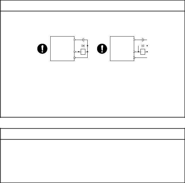
 Do not mistake the direction of the surge absorbing diode installed on the DC relay for the control signal output of brake signals, etc. Incorrect installation may lead to signals not being output when trouble occurs or the protective functions not functioning.
Servo amplifier |
24VDC |
Servo amplifier |
24VDC |
|
DOCOM |
DOCOM |
|||
|
|
|||
Control output |
RA |
Control output |
RA |
|
signal |
signal |
|||
DICOM |
|
DICOM |
|
|
For the sink output interface |
For the source output interface |
|||
 Do not connect or disconnect the connection cables between each unit, the encoder cable or PLC expansion cable while the power is ON.
 Securely tighten the cable connector fixing screws and fixing mechanisms. Insufficient fixing may lead to the cables combing off during operation.
 Do not bundle the power line or cables.
 Use applicable solderless terminals and tighten them with the specified torque.
If any solderless spade terminal is used, it may be disconnected when the terminal screw comes loose, resulting in failure.
(5) Trial operation and adjustment
 CAUTION
 Confirm and adjust the program and each parameter before operation. Unpredictable movements may occur depending on the machine.
 Extreme adjustments and changes may lead to unstable operation, so never make them.
 When using the absolute position system function, on starting up, and when the module or absolute value motor has been replaced, always perform a home position return.
 Before starting test operation, set the parameter speed limit value to the slowest value, and make sure that operation can be stopped immediately if a hazardous state occurs.
A - 7

(6) Usage methods
 CAUTION
 Immediately turn OFF the power if smoke, abnormal sounds or odors are emitted from the module, servo amplifier or servomotor.
 Always execute a test operation before starting actual operations after the program or parameters have been changed or after maintenance and inspection.
 Do not attempt to disassemble and repair the units excluding a qualified technician whom our company recognized.
 Do not make any modifications to the unit.
 Keep the effect or electromagnetic obstacles to a minimum by installing a noise filter or by using wire shields, etc.
Electromagnetic obstacles may affect the electronic devices used near the module or servo amplifier.
 When using the CE Mark-compliant equipment design, refer to the "EMC Installation Guidelines" (data number IB(NA)-67339) and refer to the corresponding EMC guideline information for the servo amplifiers and other equipment.
 Note that when the reference axis speed is designated for interpolation operation, the speed of the partner axis (2nd axis, 3rd axis and 4th axis) may be larger than the set speed (larger than the speed limit value).
 Use the units with the following conditions.
Item |
Conditions |
Input power |
According to each instruction manual. |
Input frequency |
According to each instruction manual. |
Tolerable momentary power failure |
According to each instruction manual. |
A - 8
(7) Corrective actions for errors
 CAUTION
 If an error occurs in the self diagnosis of the module or servo amplifier, confirm the check details according to the instruction manual, and restore the operation.
 If a dangerous state is predicted in case of a power failure or product failure, use a servomotor with electromagnetic brakes or install a brake mechanism externally.
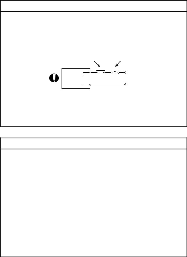
 Use a double circuit construction so that the electromagnetic brake operation circuit can be operated by emergency stop signals set externally.
Shut off with servo ON signal OFF, alarm, electromagnetic brake signal.
Servomotor
RA1
Electro-  magnetic
  brakes
Shut off with the emergency stop signal(EMG).
EMG
24VDC
 If an error occurs, remove the cause, secure the safety and then resume operation after alarm release.
 The unit may suddenly resume operation after a power failure is restored, so do not go near the machine. (Design the machine so that personal safety can be ensured even if the machine restarts suddenly.)
(8) Maintenance, inspection and part replacement
 CAUTION
 Perform the daily and periodic inspections according to the instruction manual.
 Perform maintenance and inspection after backing up the program and parameters for the module and servo amplifier.
 Do not place fingers or hands in the clearance when opening or closing any opening.
 Periodically replace consumable parts such as batteries according to the instruction manual.
 Do not touch the lead sections such as ICs or the connector contacts.
 Before touching the module, always touch grounded metal, etc. to discharge static electricity from human body. Failure to do so may cause the module to fail or malfunction.
 Do not directly touch the module's conductive parts and electronic components. Touching them could cause an operation failure or give damage to the module.
 Do not place the module or servo amplifier on metal that may cause a power leakage or wood, plastic or vinyl that may cause static electricity buildup.
 Do not perform a megger test (insulation resistance measurement) during inspection.
 When replacing the module or servo amplifier, always set the new module settings correctly.
  When the module or absolute value motor has been replaced, carry out a home position return operation using one of the following methods, otherwise position displacement could occur.
1)After writing the servo data to the positioning module using programming software, switch on the power again, then perform a home position return operation.
A - 9
 CAUTION
 After maintenance and inspections are completed, confirm that the position detection of the absolute position detector function is correct.
 Do not drop or impact the battery installed to the module.
Doing so may damage the battery, causing battery liquid to leak in the battery. Do not use the dropped or impacted battery, but dispose of it.
 Do not short circuit, charge, overheat, incinerate or disassemble the batteries.
 The electrolytic capacitor will generate gas during a fault, so do not place your face near the module or servo amplifier.
 The electrolytic capacitor and fan will deteriorate. Periodically replace these to prevent secondary damage from faults. Replacements can be made by our sales representative.
 Lock the control panel and prevent access to those who are not certified to handle or install electric equipment.
 Do not mount/remove the module onto/from the base unit more than 50 times (IEC61131-2- compliant), after the first use of the product. Failure to do so may cause malfunction.
 Do not burn or break a module and servo amplifier. Doing so may cause a toxic gas.
(9) About processing of waste
When you discard module, servo amplifier, a battery (primary battery) and other option articles, please follow the law of each country (area).
 CAUTION
 This product is not designed or manufactured to be used in equipment or systems in situations that can affect or endanger human life.
 When considering this product for operation in special applications such as machinery or systems used in passenger transportation, medical, aerospace, atomic power, electric power, or submarine repeating applications, please contact your nearest Mitsubishi sales representative.
  Although this product was manufactured under conditions of strict quality control, you are strongly advised to install safety devices to forestall serious accidents when it is used in facilities where a breakdown in the product is likely to cause a serious accident.
(10) General cautions
 CAUTION
 All drawings provided in the instruction manual show the state with the covers and safety partitions removed to explain detailed sections. When operating the product, always return the covers and partitions to the designated positions, and operate according to the instruction manual.
A - 10

REVISIONS
|
|
The manual number is given on the bottom left of the back cover. |
Print Date |
Manual Number |
Revision |
May., 2005 |
IB(NA)-0300117-A |
First edition |
Dec., 2011 |
IB(NA)-0300117-B |
[Partial correction] |
|
|
Safety instructions, Section 4.3.1 Partial change of sentence |
|
|
|
Japanese Manual Version IB-0300098
This manual confers no industrial property rights or any rights of any other kind, nor does it confer any patent licenses. Mitsubishi Electric Corporation cannot be held responsible for any problems involving industrial property rights which may occur as a result of using the contents noted in this manual.
♥ 2005 MITSUBISHI ELECTRIC CORPORATION
A - 11
INTRODUCTION
Thank you for purchasing the Mitsubishi general-purpose programmable logic controller MELSEC-Q Series. Always read through this manual, and fully comprehend the functions and performance of the Q Series PLC before starting use to ensure correct usage of this product.
|
CONTENTS |
|
|
|
SAFETY INSTRUCTIONS............................................................................................................................ |
|
A- |
1 |
|
REVISIONS................................................................................................................................................... |
|
A- 11 |
||
INTRODUCTION........................................................................................................................................... |
|
A 12 |
||
CONTENTS................................................................................................................................................... |
|
A- 13 |
||
About Manuals .............................................................................................................................................. |
|
A- 19 |
||
Using This Manual......................................................................................................................................... |
|
A- 19 |
||
Conformation to the EMC Directive.............................................................................................................. |
|
A- 19 |
||
Generic Terms and Abbreviations ................................................................................................................ |
|
A- 20 |
||
Component List ............................................................................................................................................. |
|
A- 20 |
||
|
|
|
|
|
Section 1 Product Specifications and Handling |
|
|
|
|
|
|
|
||
1. Product Outline |
1- |
1 to 1- 28 |
||
1.1 |
Positioning control.................................................................................................................................... |
|
1- |
2 |
1.1.1 Features of QD75MH........................................................................................................................ |
|
1- 2 |
||
1.1.2 Purpose and applications of positioning control............................................................................... |
|
1- |
5 |
|
1.1.3 Mechanism of positioning control ..................................................................................................... |
|
1- |
7 |
|
1.1.4 Overview of positioning control functions ......................................................................................... |
|
1- |
8 |
|
1.1.5 Outline design of positioning system............................................................................................... |
|
1- 18 |
||
1.1.6 Communicating signals between QD75MH and each module....................................................... |
|
1- 19 |
||
1.2 |
Flow of system operation........................................................................................................................ |
|
1- 22 |
|
1.2.1 Flow of all processes........................................................................................................................ |
|
1- 22 |
||
1.2.2 Outline of starting ............................................................................................................................. |
|
1- 24 |
||
1.2.3 Outline of stopping ........................................................................................................................... |
|
1- 26 |
||
1.2.4 Outline for restarting......................................................................................................................... |
|
1- 28 |
||
|
|
|
|
|
2. System Configuration |
2- |
1 to 2- |
8 |
|
2.1 |
General image of system......................................................................................................................... |
|
2- 2 |
|
2.2 |
Component list ......................................................................................................................................... |
|
2- 4 |
|
2.3 |
Applicable system .................................................................................................................................... |
|
2- 6 |
|
2.4 |
How to check the function version and SERIAL No. .............................................................................. |
|
2- 8 |
|
|
|
|
||
3. Specifications and Functions |
3- |
1 to 3- 24 |
||
3.1 |
Performance specifications...................................................................................................................... |
|
3- |
2 |
3.2 |
List of functions ....................................................................................................................................... |
|
3- |
4 |
3.2.1 QD75MH control functions................................................................................................................ |
|
3- 4 |
||
3.2.2 QD75MH main functions................................................................................................................... |
|
3- 6 |
||
|
A - 12 |
|
|
|

3.2.3 QD75MH sub functions and common functions .............................................................................. |
|
3- 8 |
||
3.2.4 Combination of QD75MH main functions and sub functions.......................................................... |
|
3- 12 |
||
3.3 Specifications of input/output signals with PLC CPU ............................................................................ |
|
3- 14 |
||
3.3.1 List of input/output signals with PLC CPU....................................................................................... |
|
3- 14 |
||
3.3.2 Details of input signals (QD75MH |
PLC CPU)............................................................................. |
|
3- 15 |
|
3.3.3 Details of output signals (PLC CPU |
QD75MH) .......................................................................... |
|
3- 17 |
|
3.4 Specifications of interfaces with external devices.................................................................................. |
|
3- 18 |
||
3.4.1 Electrical specifications of input signals .......................................................................................... |
|
3- 18 |
||
3.4.2 Signal layout for external device connection connector.................................................................. |
|
3- 19 |
||
3.4.3 List of input signal details................................................................................................................. |
|
|
3- 20 |
|
3.4.4 Interface internal circuit .................................................................................................................... |
|
|
3- 21 |
|
3.5 External circuit design............................................................................................................................. |
|
|
3- 22 |
|
|
|
|
||
4. Installation, Wiring and Maintenance of the Product |
4- |
1 to 4- 18 |
||
4.1 Outline of installation, wiring and maintenance....................................................................................... |
|
4- |
2 |
|
4.1.1 Installation, wiring and maintenance procedures............................................................................. |
|
4- |
2 |
|
4.1.2 Names of each part........................................................................................................................... |
|
|
4- 3 |
|
4.1.3 Handling precautions ........................................................................................................................ |
|
|
4- |
5 |
4.2 Installation ................................................................................................................................................ |
|
|
4- |
7 |
4.2.1 Precautions for installation................................................................................................................ |
|
|
4- |
7 |
4.3 Wiring....................................................................................................................................................... |
|
|
4- 10 |
|
4.3.1 Precautions for wiring....................................................................................................................... |
|
|
4- 10 |
|
4.4 Confirming the installation and wiring..................................................................................................... |
|
|
4- 16 |
|
4.4.1 Items to confirm when installation and wiring are completed ......................................................... |
|
4- 16 |
||
4.5 Maintenance............................................................................................................................................ |
|
|
4- 17 |
|
4.5.1 Precautions for maintenance ........................................................................................................... |
|
|
4- 17 |
|
4.5.2 Disposal instructions ........................................................................................................................ |
|
|
4- 17 |
|
|
|
|
||
5. Data Used for Positioning Control (List of buffer memory addresses) |
5- |
1 to 5-172 |
||
5.1 Types of data............................................................................................................................................ |
|
|
5- 2 |
|
5.1.1 Parameters and data required for control......................................................................................... |
|
5- |
2 |
|
5.1.2 Setting items for positioning parameters .......................................................................................... |
|
5- |
6 |
|
5.1.3 Setting items for OPR parameters.................................................................................................... |
|
|
5- 8 |
|
5.1.4 Setting items for servo parameters................................................................................................... |
|
|
5- |
9 |
5.1.5 Setting items for positioning data..................................................................................................... |
|
|
5- 11 |
|
5.1.6 Setting items for block start data ..................................................................................................... |
|
|
5- 14 |
|
5.1.7 Setting items for condition data ....................................................................................................... |
|
|
5- 15 |
|
5.1.8 Types and roles of monitor data ...................................................................................................... |
|
|
5- 18 |
|
5.1.9 Types and roles of control data ....................................................................................................... |
|
|
5- 20 |
|
5.2 List of parameters ................................................................................................................................... |
|
|
5- 24 |
|
5.2.1 Basic parameters 1 .......................................................................................................................... |
|
|
5- 24 |
|
5.2.2 Basic parameters 2 .......................................................................................................................... |
|
|
5- 28 |
|
5.2.3 Detailed parameters 1...................................................................................................................... |
|
|
5- 30 |
|
5.2.4 Detailed parameters 2...................................................................................................................... |
|
|
5- 38 |
|
5.2.5 OPR basic parameters..................................................................................................................... |
|
|
5- 50 |
|
5.2.6 OPR detailed parameters ................................................................................................................ |
|
|
5- 56 |
|
|
A - 13 |
|
|
|
5.2.7 Servo parameters (Basic setting) .................................................................................................... |
5- 62 |
||
5.2.8 Servo parameters (Gain • filter setting)........................................................................................... |
5- 68 |
||
5.2.9 Servo parameters (Expansion setting) ............................................................................................ |
5- 80 |
||
5.2.10 Servo parameters (Input/Output setting)....................................................................................... |
5- 86 |
||
5.3 |
List of positioning data ............................................................................................................................ |
5- 90 |
|
5.4 |
List of block start data ............................................................................................................................ |
5-106 |
|
5.5 |
List of condition data .............................................................................................................................. |
5-112 |
|
5.6 |
List of monitor data................................................................................................................................. |
5-118 |
|
5.6.1 System monitor data ....................................................................................................................... |
5-118 |
||
5.6.2 Axis monitor data............................................................................................................................. |
5-128 |
||
5.7 |
List of control data.................................................................................................................................. |
5-148 |
|
5.7.1 System control data ........................................................................................................................ |
5-148 |
||
5.7.2 Axis control data.............................................................................................................................. |
5-150 |
||
|
|
||
6. Sequence Program Used for Positioning Control |
6- 1 to 6- 72 |
||
6.1 |
Precautions for creating program ........................................................................................................... |
6- |
2 |
6.2 |
List of devices used................................................................................................................................. |
6- |
5 |
6.3 |
Creating a program ................................................................................................................................. |
6- 15 |
|
6.3.1 General configuration of program.................................................................................................... |
6- 15 |
||
6.3.2 Positioning control operation program............................................................................................. |
6- 16 |
||
6.4 |
Positioning program examples ............................................................................................................... |
6- 20 |
|
6.5 |
Program details ....................................................................................................................................... |
6- 52 |
|
6.5.1 Initialization program ........................................................................................................................ |
6- 52 |
||
6.5.2 Start details setting program ............................................................................................................ |
6- 53 |
||
6.5.3 Start program.................................................................................................................................... |
6- 55 |
||
6.5.4 Continuous operation interrupt program.......................................................................................... |
6- 64 |
||
6.5.5 Restart program ............................................................................................................................... |
6- 66 |
||
6.5.6 Stop program.................................................................................................................................... |
6- 69 |
||
|
|
||
7. Memory Configuration and Data Process |
7- 1 to 7- 20 |
||
7.1 |
Configuration and roles of QD75MH memory......................................................................................... |
7- 2 |
|
7.1.1 Configuration and roles of QD75MH memory.................................................................................. |
7- 2 |
||
7.1.2 Buffer memory area configuration .................................................................................................... |
7- |
5 |
|
7.2 |
Data transmission process ...................................................................................................................... |
7- 8 |
|
A - 14

Section 2 Control Details and Setting
8. OPR Control |
8- 1 to 8- 16 |
|
8.1 Outline of OPR control ............................................................................................................................. |
8- |
2 |
8.1.1 Two types of OPR control................................................................................................................. |
8- 2 |
|
8.2 Machine OPR........................................................................................................................................... |
8- 5 |
|
8.2.1 Outline of the machine OPR operation............................................................................................. |
8- 5 |
|
8.2.2 Machine OPR method....................................................................................................................... |
8- 6 |
|
8.2.3 OPR method (1): Near-point dog method ........................................................................................ |
8- 7 |
|
8.2.4 OPR method (2): Count method 1) .................................................................................................. |
8- 9 |
|
8.2.5 OPR method (3): Count method 2) ................................................................................................. |
8- 11 |
|
8.2.6 OPR method (4): Data set method.................................................................................................. |
8- 13 |
|
8.3 Fast OPR................................................................................................................................................. |
8- 14 |
|
8.3.1 Outline of the fast OPR operation.................................................................................................... |
8- 14 |
|
8.4 Selection of OPR set condition .............................................................................................................. |
8- 16 |
|
8.4.1 Outline of the selection of OPR set condition.................................................................................. |
8- 16 |
|
|
|
|
9. Major Positioning Control |
9- 1 to 9-116 |
|
9.1 Outline of major positioning controls ....................................................................................................... |
9- |
2 |
9.1.1 Data required for major positioning control ...................................................................................... |
9- |
4 |
9.1.2 Operation patterns of major positioning controls ............................................................................. |
9- |
5 |
9.1.3 Designating the positioning address................................................................................................ |
9- 15 |
|
9.1.4 Confirming the current value............................................................................................................ |
9- 16 |
|
9.1.5 Control unit "degree" handling ......................................................................................................... |
9- 18 |
|
9.1.6 Interpolation control.......................................................................................................................... |
9- 21 |
|
9.2 Setting the positioning data ................................................................................................................... |
9- 25 |
|
9.2.1 Relation between each control and positioning data ...................................................................... |
9- 25 |
|
9.2.2 1-axis linear control .......................................................................................................................... |
9- 27 |
|
9.2.3 2-axis linear interpolation control ..................................................................................................... |
9- 29 |
|
9.2.4 3-axis linear interpolation control ..................................................................................................... |
9- 33 |
|
9.2.5 4-axis linear interpolation control ..................................................................................................... |
9 -39 |
|
9.2.6 1-axis fixed-feed control................................................................................................................... |
9- 44 |
|
9.2.7 2-axis fixed-feed control (interpolation) ........................................................................................... |
9- 46 |
|
9.2.8 3-axis fixed-feed control (interpolation) ........................................................................................... |
9- 48 |
|
9.2.9 4-axis fixed-feed control (interpolation) .......................................................................................... |
9- 52 |
|
9.2.10 2-axis circular interpolation control with sub point designation .................................................... |
9- 54 |
|
9.2.11 2-axis circular interpolation control with center point designation ................................................ |
9- 60 |
|
9.2.12 1-axis speed control ....................................................................................................................... |
9- 68 |
|
9.2.13 2-axis speed control ....................................................................................................................... |
9- 71 |
|
9.2.14 3-axis speed control ....................................................................................................................... |
9- 74 |
|
9.2.15 4-axis speed control ....................................................................................................................... |
9- 78 |
|
9.2.16 Speed-position switching control (INC mode)............................................................................... |
9- 83 |
|
9.2.17 Speed-position switching control (ABS mode).............................................................................. |
9- 91 |
|
9.2.18 Position-speed switching control ................................................................................................... |
9- 99 |
|
9.2.19 Current value changing................................................................................................................ |
9- 106 |
|
A - 15 |
|
|
9.2.20 NOP instruction ............................................................................................................................ |
9- 111 |
||
9.2.21 JUMP instruction .......................................................................................................................... |
9- 112 |
||
9.2.22 LOOP............................................................................................................................................ |
9- 114 |
||
9.2.23 LEND ............................................................................................................................................ |
9- 115 |
||
|
|
||
10. High-Level Positioning Control |
10- 1 to 1026 |
||
10.1 |
Outline of high-level positioning control .............................................................................................. |
10- |
2 |
10.1.1 Data required for high-level positioning control............................................................................ |
10- |
3 |
|
10.1.2 "Block start data" and "condition data" configuration................................................................... |
10- |
4 |
|
10.2 |
High-level positioning control execution procedure ............................................................................ |
10- |
6 |
10.3 |
Setting the block start data .................................................................................................................. |
10- |
7 |
10.3.1 Relation between various controls and block start data .............................................................. |
10- |
7 |
|
10.3.2 Block start (normal start) .............................................................................................................. |
10- |
8 |
|
10.3.3 Condition start .............................................................................................................................. |
1010 |
||
10.3.4 Wait start....................................................................................................................................... |
1011 |
||
10.3.5 Simultaneous start ...................................................................................................................... |
1012 |
||
10.3.6 Repeated start (FOR loop) ......................................................................................................... |
1013 |
||
10.3.7 Repeated start (FOR condition) .................................................................................................. |
1014 |
||
10.3.8 Restrictions when using the NEXT start...................................................................................... |
1015 |
||
10.4 |
Setting the condition data ................................................................................................................... |
1016 |
|
10.4.1 Relation between various controls and the condition data ......................................................... |
1016 |
||
10.4.2 Condition data setting examples ................................................................................................. |
1019 |
||
10.5 |
Multiple axes simultaneous start control ............................................................................................ |
1020 |
|
10.6 |
Start program for high-level positioning control ................................................................................. |
1023 |
|
10.6.1 Starting high-level positioning control.......................................................................................... |
1023 |
||
10.6.2 Example of a start program for high-level positioning control .................................................... |
1024 |
||
|
|
||
11. Manual Control |
11- 1 to 1136 |
||
11.1 |
Outline of manual control .................................................................................................................... |
11- |
2 |
11.1.1 Three manual control methods..................................................................................................... |
11- 2 |
||
11.2 |
JOG operation...................................................................................................................................... |
11- 4 |
|
11.2.1 Outline of JOG operation .............................................................................................................. |
11- 4 |
||
11.2.2 JOG operation execution procedure ............................................................................................ |
11- 7 |
||
11.2.3 Setting the required parameters for JOG operation..................................................................... |
11- |
8 |
|
11.2.4 Creating start programs for JOG operation................................................................................. |
1110 |
||
11.2.5 JOG operation example............................................................................................................... |
1113 |
||
11.3 |
Inching operation................................................................................................................................. |
1117 |
|
11.3.1 Outline of inching operation ......................................................................................................... |
1117 |
||
11.3.2 Inching operation execution procedure ....................................................................................... |
1120 |
||
11.3.3 Setting the required parameters for inching operation ............................................................... |
1121 |
||
11.3.4 Creating a program to enable/disable the inching operation...................................................... |
1122 |
||
11.3.5 Inching operation example........................................................................................................... |
1125 |
||
11.4 |
Manual pulse generator operation...................................................................................................... |
1127 |
|
11.4.1 Outline of manual pulse generator operation.............................................................................. |
1127 |
||
11.4.2 Manual pulse generator operation execution procedure ............................................................ |
1131 |
||
11.4.3 Setting the required parameters for manual pulse generator operation .................................... |
1132 |
||
11.4.4 Creating a program to enable/disable the manual pulse generator operation........................... |
1133 |
||
|
A - 16 |
|
|
12. Control Sub Functions |
12- 1 to 12-106 |
||
12.1 |
Outline of sub functions ....................................................................................................................... |
12- |
2 |
12.1.1 Outline of sub functions ................................................................................................................ |
12- |
2 |
|
12.2 |
Sub functions specifically for machine OPR ....................................................................................... |
12- 4 |
|
12.2.1 OPR retry function......................................................................................................................... |
12- |
4 |
|
12.2.2 OP shift function ........................................................................................................................... |
12- |
8 |
|
12.3 |
Functions for compensating the control ............................................................................................. |
1211 |
|
12.3.1 Backlash compensation function................................................................................................. |
1211 |
||
12.3.2 Electronic gear function ............................................................................................................... |
1213 |
||
12.3.3 Near pass function ....................................................................................................................... |
1220 |
||
12.4 |
Functions to limit the control ............................................................................................................... |
1223 |
|
12.4.1 Speed limit function...................................................................................................................... |
1223 |
||
12.4.2 Torque limit function..................................................................................................................... |
1225 |
||
12.4.3 Software stroke limit function....................................................................................................... |
1229 |
||
12.4.4 Hardware stroke limit function ..................................................................................................... |
1235 |
||
12.4.5 Forced stop function..................................................................................................................... |
1239 |
||
12.5 |
Functions to change the control details.............................................................................................. |
1242 |
|
12.5.1 Speed change function ................................................................................................................ |
1242 |
||
12.5.2 Override function.......................................................................................................................... |
1249 |
||
12.5.3 Acceleration/deceleration time change function ......................................................................... |
1252 |
||
12.5.4 Torque change function ............................................................................................................... |
1256 |
||
12.6 |
Absolute position system .................................................................................................................... |
1259 |
|
12.7 |
Other functions.................................................................................................................................... |
1261 |
|
12.7.1 Step function................................................................................................................................. |
1261 |
||
12.7.2 Skip function................................................................................................................................. |
1266 |
||
12.7.3 M code output function................................................................................................................. |
1269 |
||
12.7.4 Teaching function......................................................................................................................... |
1273 |
||
12.7.5 Target position change function .................................................................................................. |
1279 |
||
12.7.6 Command in-position function ..................................................................................................... |
1283 |
||
12.7.7 Acceleration/deceleration processing function............................................................................ |
1286 |
||
12.7.8 Pre-reading start function............................................................................................................. |
1289 |
||
12.7.9 Deceleration start flag function................................................................................................... |
1294 |
||
12.7.10 Stop command processing for deceleration stop function ..................................................... |
1298 |
||
12.7.11 Speed control 10 x multiplier setting for degree axis function ............................................. |
12101 |
||
12.7.12 Operation setting for incompletion of OPR function ............................................................. |
12103 |
||
12.8 Servo ON/OFF .................................................................................................................................. |
12105 |
||
12.8.1 Servo ON/OFF ........................................................................................................................... |
12105 |
||
12.8.2 Follow up function ...................................................................................................................... |
12106 |
||
|
|
||
13. Common Functions |
13- 1 to 13- 8 |
||
13.1 |
Outline of common functions ............................................................................................................... |
13- 2 |
|
13.2 |
Parameter initialization function........................................................................................................... |
13- |
3 |
13.3 |
Execution data backup function .......................................................................................................... |
13- 5 |
|
13.4 |
External signal selection function ........................................................................................................ |
13- |
7 |
13.5 |
External I/O signal logic switching function......................................................................................... |
13- |
8 |
A - 17
14. Dedicated Instructions |
14- |
1 to 1418 |
|||||||
14.1 List of dedicated instructions ............................................................................................................... |
|
14- |
2 |
||||||
14.2 Interlock during dedicated instruction is executed.............................................................................. |
|
14- |
2 |
||||||
14.3 PSTRT1, PSTRT2, PSTRT3, PSTRT4............................................................................................... |
|
14- 3 |
|||||||
14.4 TEACH1, TEACH2, TEACH 3, TEACH 4 ........................................................................................... |
|
14- 7 |
|||||||
14.5 PFWRT................................................................................................................................................ |
|
1411 |
|||||||
14.6 PINIT.................................................................................................................................................... |
|
1415 |
|||||||
|
|
|
|
|
|
|
|
|
|
15. Troubleshooting |
15- |
1 to 1560 |
|||||||
15.1 Error and warning details..................................................................................................................... |
|
15- |
2 |
||||||
15.2 List of errors ......................................................................................................................................... |
|
15- |
6 |
||||||
15.2.1 QD75MH detection error............................................................................................................... |
|
15- 6 |
|||||||
15.2.2 MR-J3-B detection error............................................................................................................... |
|
1536 |
|||||||
15.3 List of warnings ................................................................................................................................... |
|
1550 |
|||||||
15.3.1 QD75MH detection warning......................................................................................................... |
|
1550 |
|||||||
15.3.2 MR-J3-B detection warning ......................................................................................................... |
|
1556 |
|||||||
15.4 LED display functions ......................................................................................................................... |
|
1560 |
|||||||
|
|
|
|
|
|
|
|
||
Appendices |
Appendix- 1 to Appendix-72 |
||||||||
Appendix 1 Functions........................................................................................................................ |
Appendix- 3 |
||||||||
Appendix 1.1 Multiple CPU correspond function.......................................................................... |
Appendix- 3 |
||||||||
Appendix 1.2 The combination of software package for QD75MH and QCPU .......................... |
Appendix- 3 |
||||||||
Appendix 2 Positioning data (No.1 to 600) List of buffer memory addresses................................. |
Appendix- 4 |
||||||||
Appendix 3 Connection with servo amplifiers ................................................................................. |
Appendix28 |
||||||||
Appendix 3.1 Connection of SSCNET |
|
|
cables |
Appendix28 |
|||||
|
|
||||||||
|
|
||||||||
Appendix 3.2 Wiring of SSCNET |
|
|
cables |
Appendix30 |
|||||
|
|
||||||||
|
|
||||||||
Appendix 4 Connection with external device connector ................................................................. |
Appendix34 |
||||||||
Appendix 4.1 Connector............................................................................................................... |
Appendix34 |
||||||||
Appendix 4.2 Wiring of manual pulse generator cable ............................................................... |
Appendix36 |
||||||||
Appendix 5 Comparisons with conventional positioning modules.................................................. |
Appendix37 |
||||||||
Appendix 5.1 Comparisons with QD75P model.......................................................................... |
Appendix37 |
||||||||
Appendix 5.2 Comparisons with QD75M1/ QD75M2/ QD75M4 models ................................... |
Appendix38 |
||||||||
Appendix 6 Positioning control troubleshooting .............................................................................. |
Appendix51 |
||||||||
Appendix 7 List of buffer memory addresses.................................................................................. |
Appendix57 |
||||||||
Appendix 8 External dimension drawing ......................................................................................... |
Appendix71 |
||||||||
|
|
||||||||
INDEX |
Index- 1 to Index - 10 |
||||||||
INDEX..................................................................................................................................................... |
|
Index - 1 |
|||||||
A - 18

About Manuals
The following manuals are also related to this product.
In necessary, order them by quoting the details in the tables below.
Related Manuals
Manual Name
Manual Number
(Model Code)
GX Configurator-QP Operating Manual
Describes how to use GX Configurator-QP for the following and other purposes: creating data (parameters, positioning data, etc.), sending the data to the module, monitoring the positioning
SH-080172
operations, and testing.
(13JU19)
(The manual is supplied with the software.)
Using This Manual
The symbols used in this manual are shown below.
Pr. |
....... |
Symbol indicating positioning parameter and OPR parameter item. |
|
....... |
Symbol indicating positioning data, block start data and condition |
Da. |
||
|
|
data item. |
Md. |
....... |
Symbol indicating monitor data item. |
Cd. |
....... |
Symbol indicating control data item. |
(A serial No. is inserted in the  mark.)
Conformation to the EMC Directive
The CE logo is printed on the rating plate on the main body of the PLC that conforms to the EMC directive instruction.
To make this product conform to the EMC directive instruction, please refer to section 4.3.1 "Precautions for wiring" of the chapter 4 "Installation, Wiring and Maintenance of the Product" and the EMC Installation Guidelines (IB(NA)67339).
Representation of numerical values used in this manual.
 Buffer memory addresses, error codes and warning codes are represented in decimal.
 X/Y devices are represented in hexadecimal.
 Setting data and monitor data are represented in decimal or hexadecimal. Data ended by "H" or "h" are represented in hexadecimal.
(Example) 10.........Decimal 10H ......Hexadecimal
A - 19
Generic Terms and Abbreviations
|
|
|
|
|
|
|
Unless specially noted, the following generic terms and abbreviations are used in this |
||||
|
|
|
|
|
|
|
manual. |
||||
|
|
|
|
|
|
|
|
|
|
|
|
Generic term/abbreviation |
|
|
|
|
Details of generic term/abbreviation |
||||||
PLC CPU |
|
|
Generic term for PLC CPU on which QD75MH can be mounted. |
||||||||
QD75MH |
|
|
Generic term for positioning module QD75MH1, QD75MH2 and QD75MH4. |
||||||||
|
|
|
|
|
|
|
|
The module type is described to indicate a specific module. |
|||
MR-J3-B |
|
|
Servo amplifier: Abbreviation for MR-J3- B. ( = capacity) |
||||||||
Peripheral device |
|
Generic term for DOS/V personal computer that can run the following "GX Developer" and |
|||||||||
|
|
|
|
|
|
|
|
"GX Configurator-QP". |
|||
GX Developer |
|
Abbreviation for GX Developer (SW4D5C-GPPW-E or later). |
|||||||||
GX Configurator-QP |
|
Abbreviation for GX Configurator-QP (SW2D5C-QD75P-E (Version 2.21X) or later). |
|||||||||
Servo amplifier (drive unit) |
|
Abbreviation for SSCNET |
|
|
compatible servo amplifier (drive unit). |
||||||
|
|
|
|||||||||
|
|
|
|||||||||
Manual pulse generator |
|
Abbreviation for manual pulse generator (MR-HDP01) (prepared by user). |
|||||||||
DOS/V personal computer |
IBM PC/AT® and compatible DOS/V compliant personal computer. |
||||||||||
Personal computer |
|
Generic term for DOS/V personal computer. |
|||||||||
Workpiece |
|
|
Generic term for moving body such as workpiece and tool, and for various control targets. |
||||||||
Axis 1, axis 2, axis 3, |
|
Indicates each axis connected to QD75MH. |
|||||||||
axis 4 |
|
|
|
|
|
|
|||||
1-axis, 2-axis, 3-axis, |
|
Indicates the number of axes. (Example: 2-axis = Indicates two axes such as axis 1 and axis 2, |
|||||||||
4-axis |
|
|
axis 2 and axis 3, and axis 3 and axis 1.) |
||||||||
|
|
|
|
|
|
||||||
OPR |
|
|
Generic term for "Home position return". |
||||||||
OP |
|
|
Generic term for "Home position". |
||||||||
SSCNET |
|
|
|
|
|
(Note) |
|
High speed synchronous communication network between QD75MH and servo amplifier. |
|||
|
|
|
|
|
|
|
|||||
(Note): SSCNET: Servo System Controller NETwork
Component List
The table below shows the component included in respective positioning modules:
Module name |
|
Quantity |
|
|
QD75MH1 |
QD75MH2 |
QD75MH4 |
||
|
||||
QD75MH1 positioning module |
1 |
|
|
|
QD75MH2 positioning module |
|
1 |
|
|
QD75MH4 positioning module |
|
|
1 |
|
Before Using the Product |
|
1 |
|
A - 20

Section 1 Product Specifications and Handling
Section 1
Section 1 is configured for the following purposes (1) to (5).
(1)To understand the outline of positioning control, and the QD75MH specifications and functions
(2)To carry out actual work such as installation and wiring
(3)To set parameters and data required for positioning control
(4)To create a PLC program required for positioning control
(5)To understand the memory configuration and data transmission process
When diverting any of the program examples introduced in this manual to the actual system, fully verify that there are no problems in the controllability of the target system.
Read "Section 2" for details on each control.
Chapter 1 |
Product outline .............................................................................................. |
1- 1 to 1- |
28 |
Chapter 2 |
System configuration .................................................................................... |
2- 1 to 2- |
8 |
Chapter 3 Specifications and Functions........................................................................ |
3- 1 to 3- |
24 |
|
Chapter 4 Installation, Wiring and Maintenance of the Product ................................... |
4- 1 to 4- |
16 |
|
Chapter 5 Data Used for Positioning Control................................................................ |
5- 1 to 5-172 |
||
Chapter 6 |
PLC Program Used for Positioning Control ................................................. |
6- 1 to 6- 72 |
|
Chapter 7 |
Memory Configuration and Data Process.................................................... |
7- 1 to 7- 20 |
|

MEMO

1
Chapter 1 Product Outline
The purpose and outline of positioning control using QD75MH are explained in this chapter. Reading this chapter will help you understand what can be done using the positioning system and which procedure to use for a specific purpose.
By understanding "What can be done", and "Which procedure to use" beforehand, the positioning system can be structured smoothly.
1.1 Positioning control ........................................................................................................ |
1- |
2 |
|
1.1.1 |
Features of QD75MH ..................................................................................... |
1- 2 |
|
1.1.2 Purpose and applications of positioning control ............................................ |
1- |
5 |
|
1.1.3 Mechanism of positioning control................................................................... |
1- |
7 |
|
1.1.4 Overview of positioning control functions....................................................... |
1- |
8 |
|
1.1.5 Outline design of positioning system............................................................. |
1- 18 |
||
1.1.6 Communicating signals between QD75MH and each module .................... |
1- 19 |
||
1.2 Flow of system operation ............................................................................................ |
1- 22 |
||
1.2.1 |
Flow of all processes ..................................................................................... |
1- 22 |
|
1.2.2 |
Outline of starting........................................................................................... |
1- 24 |
|
1.2.3 |
Outline of stopping......................................................................................... |
1- 26 |
|
1.2.4 |
Outline for restarting ...................................................................................... |
1- 28 |
|
1 - 1

1 PRODUCT OUTLINE
1.1 Positioning control
1.1.1 Features of QD75MH
The features of the QD75MH are shown below.
MELSEC-Q
(1)Availability of one, two, and four axis modules
(a)One, two and four axis positioning modules are available.
They can be selected according to the PLC CPU type and the number of required control axes. (Refer to Section 2.2.)
(b)For connecting any of the QD75MH modules to the base unit, a single slot and 32 dedicated I/O channels are required.
Within the limit imposed by the maximum number of inputs and outputs supported by the PLC CPU, up to 64 modules can be used. (Refer to Section 2.3.)
(2)Wide variety of positioning control functions
(a)A wide variety of positioning control functions essential to any positioning system are supported: positioning to an arbitrary position, fixed-feed control, equal-speed control, and so on. (Refer to Section 5.3 and 9.2.)
1)Up to 600 positioning data items, including such information as positioning addresses, control systems, and operation patterns, can be prepared for each axis.
Using the prepared positioning data, the positioning control is performed independently for each axis. (In addition, such controls as interpolation involving two to four axes and simultaneous startup of multiple axes are possible.)
2)Independent control of each axis can be achieved in linear control mode (executable simultaneously over four axes).
Such control can either be the independent positioning control using a single positioning data or the continuous positioning control enabled by the continuous processing of multiple positioning data.
3)Coordinated control over multiple axes can take the form of either the linear interpolation through the speed or position control of two to four axes or the circular interpolation involving two axes.
Such control can either be the independent positioning control using a single positioning data or the continuous positioning control enabled by the continuous processing of multiple positioning data.
(b)For each positioning data, the user can specify any of the following control systems: position control, speed control, speed-position switching control, position-speed switching control, and so on. (Refer to Section 5.3 and 9.2.)
1 - 2

1 PRODUCT OUTLINE
MELSEC-Q
(c)Continuous positioning control using multiple positioning data can be executed in accordance with the operation patterns the user assigned to the positioning data. (Refer to Section 5.3 and 9.1.2.)
Continuous positioning control can be executed over multiple blocks, where each block consists of multiple positioning data. (Refer to Section 10.3.2.)
(d)OPR control is given additional features (Refer to Section 8.2.)
Four different machine OPR methods are provided: the near point dog method, two count methods, and the data set method.
(e)Two acceleration/deceleration control methods are provided: automatic trapezoidal acceleration/deceleration and S-pattern acceleration/ deceleration. (Refer to Section 12.7.7.)
(3)Quick startup (Refer to Section 3.1.)
A positioning operation starts up quickly taking as little as 3.5 ms to 4 ms. When operation using simultaneous start function or interpolation operation is executed, the axes start without delay.
(Example) Axis 1 and Axis 3 are started by the |
: No delay in Axis 1 and |
simultaneous start function |
Axis 3 start |
Axis 2 and Axis 4 are started by the |
: No delay in Axis 2 and |
interpolation operation |
Axis 4 start |
(4)SSCNET makes the connection to the servo amplifier possible
(a)The QD75MH can be directly connected to the servo amplifier using the MELSERVO (Mitsubishi's servo amplifier: MR-J3-B).
(b)Because the SSCNET cable is used to connect the QD75MH and the servo amplifier, or servo amplifiers, saving wiring can be realized. The cable between the QD75MH and servo amplifier or servo amplifiers can be extended up to 50m (164.04ft.).
(c)By the use of SSCNET cable (Optical communication), influence of electromagnetic noise and others from servo amplifier, etc. are reduced.
(d)The servo parameters can be set on the QD75MH side to write or read them to/from the servo amplifier using the SSCNET .
.
(e)The actual current value and error description contained in the servo can be checked by the buffer memory of the QD75MH.
(5)Easy application to the absolute position system
(a)The absolute position-corresponding servo amplifier is connected to have an application to the absolute position system.
(b)Once the OP have been established, the OPR operation can also be made unnecessary when the power is supplied.
(c)With the absolute position system, the data set method OPR is used to establish the OP.
(d)When the setting unit is "degree", the absolute position system with unlimited length feed can be configured.
1 - 3

1 PRODUCT OUTLINE
MELSEC-Q
(6) Control can be realized with the mechanical system input
The external inputs, such as external start, stop, and speed/position switching is used to perform the positioning control without using the PLC program.
(7) Easy maintenance
Each QD75MH positioning module incorporates the following improvements in maintainability:
(a)Data such as the positioning data and parameters can be stored on a flash ROM inside the QD75MH, eliminating the need of a battery for retaining data. (Refer to Section 7.1.1.)
(b)Error messages are classified in more detail to facilitate the initial troubleshooting procedure. (Refer to Section 15.1.)
(c)The module retains 16 error messages and 16 warning messages recently output, offering more complete error and warning histories.
(Refer to Section 5.6.1.)
(8)Support of intelligent function module dedicated instructions
Dedicated instructions such as the positioning start instruction, and teaching instruction are provided.
The use of such dedicated instruction simplifies PLC programs.(Refer to Chapter 14.)
(9) Setups, monitoring, and testing through GX Configurator-QP
Using GX Configurator-QP, the user can control the QD75MH parameters and positioning data without having to be conscious of the buffer memory addresses. Moreover, GX Configurator-QP has a test function which allows the user to check the wiring before creating a PLC program for positioning control, or test operation the QD75MH using created parameters and positioning data for checking their integrity.
The control monitor function of GX Configurator-QP allows the user to debug programs efficiently.
(10) Addition of forced stop function
As forced stop input signal to the connector for external equipment connection is added, batch forced stop is available for all axes of servo amplifier.
(Refer to Section 12.4.5.)
Selection for whether using "Forced stop input signal" or not can be made with parameter.
1 - 4

1 PRODUCT OUTLINE
1.1.2 Purpose and applications of positioning control
MELSEC-Q
"Positioning" refers to moving a moving body, such as a workpiece or tool (hereinafter, generically called "workpiece") at a designated speed, and accurately stopping it at the target position. The main application examples are shown below.
 Punch press (X, Y feed positioning)
Y axis |
Gear and ball screw |
Y axis |
X axis |
320mm |
160mm |
15m/min |
servomotor |
|
|
(2000r/min) |
|||
|
|
|
Y axis |
Press |
15m/min |
|
|
|
|
|
|||
|
|
|
|
punching |
(1875r/min) |
|
|
|
|
|
|
12s |
|
Servo |
Press head |
|
|
|
|
|
|
|
|
|
|
|
|
|
|
|
|
|
|
|
|
|
|
|
X axis |
|||||||||||||||||
amplifier |
|
|
|
|
|
|
|
|
|
|
|
|
|
|
|
|
|
|
|
|
|
|
|
|
|
|
|
|
|
|
|
|
|
|
|
|
|
|
|
|
Gear and rack & pinion |
|
|
|
|
|
|
|
|
|
|
|
|
|
|
|
|
|
X axis |
|
|
PLC |
|||||||||||||||||||||||
|
|
|
|
|
|
|
|
|
|
|
|
|
|
|
|
servomotor |
|
|
MELSEC-Q QD75MH |
|||||||||||||||||||||||
|
|
|||||||||||||||||||||||||||||||||||||||||
|
Servo |
|
|
|
|
|||||||||||||||||||||||||||||||||||||
Y axis |
amplifier |
|
|
|
|
|
|
|||||||||||||||||||||||||||||||||||
|
|
|
|
|
||||||||||||||||||||||||||||||||||||||
|
|
|
|
|
|
|
|
|
|
|
|
|
|
|
|
|
|
|
|
|
|
|
|
|
|
|
|
|
|
|
|
|
|
|
|
|
|
|
|
|
|
|
|
|
|
|
|
|
|
|
|
|
|
|
|
|
|
|
|
|
|
|
|
|
|
|
|
|
|
|
|
|
|
|
|
|
|
|
|
|
|
|
|
|
|
|
|
|
|
|
|
|
|
|
|
|
|
|
|
|
|
|
|
|
|
|
|
|
|
|
|
|
|
|
|
|
|
|
|
|
|
|
|
|
|
|
X axis |
|
|
|
|
|
|
|
|
|
|
|
|
|
|
|
|
|
|
|
|
|
|
|
|
|
|
|
|
|
|
|
|
|
|
|
|
|
|
|
|
|
|
||
•To punch insulation material or leather, etc., as the same shape at a high yield, positioning is carried out with the X axis and Y axis servos.
•After positioning the table with the X axis servo, the press head is positioned with the Y axis servo, and is then punched with the press.
•When the material type or shape changes, the press head die is changed, and the positioning pattern is changed.
 Palletizer
Conveyor control |
|
|
Conveyor |
|
|
|
||||
|
|
|
|
|
|
|||||
Servomotor |
|
|
|
|
|
|
|
|
|
|
|
|
|
|
|
|
|
|
|
||
(with brakes) |
|
|
|
|
|
|
|
|
|
|
|
|
|
|
|
|
|
|
|
|
|
Servo |
|
G |
|
|
|
|
Position detector |
|
||
|
|
|
|
|
|
|||||
|
|
|
|
|
|
|
|
|||
|
|
|
|
|||||||
|
Reduction |
|
|
|
|
Palletizer |
||||
amplifier |
|
|
|
|
|
|||||
|
gears |
|
|
|
|
|
|
|
||
|
|
Unloader control |
||||||||
|
|
|
Ball screw |
|
|
|
|
|
||
|
|
|
(From QD75MH) |
|
|
|
||||
|
|
|
|
|
|
|||||
|
|
|
PLC |
|
|
|
|
|
||
|
|
|
|
|
|
|
||||
|
|
|
MELSEC-Q |
|
|
|
|
|
||
|
|
|
QD75MH |
|
|
|
|
|
||
|
|
|
|
|
|
|
||||
•Using the servo for one axis, the palletizer is positioned at a high accuracy.
•The amount to lower the palletizer according to the material thickness is saved.
 Compact machining center (ATC magazine positioning)
Servomotor
|
|
|
Coupling Reduction |
|
|
|
|
|
|
|
|
|
|
|
|
|
|
|
|||||||||||
|
|
|
|
|
gears |
ATC tool |
|
|
|
|
|
|
|
|
|
|
|
|
|
|
|
||||||||
|
|
|
|
|
|
|
|
|
|
|
|
|
|
|
|
|
|
||||||||||||
|
|
|
|
|
|
|
|
|
|
|
|
|
|
|
|
|
|
|
|
|
|
|
|
|
|||||
Servo |
|
|
|
|
|
|
|
|
magazine |
|
|
|
|
|
|
|
|
|
|
|
|
|
|
|
|||||
|
|
|
|
|
|
|
|
|
|
|
|
|
|
|
|
|
|
|
|
|
|
|
|
|
|
|
|
||
amplifier |
|
|
|
|
|
Tool |
|
|
|
|
|
|
|
|
|
|
|
|
|
|
|
|
|
|
|
|
|||
|
|
|
Positioning |
|
|
|
|
|
|
|
|
|
|
|
|
|
|
|
|
|
|
|
|
||||||
|
|
|
|
|
|
|
|
|
|
|
|
|
|
|
|
|
|
|
|
|
|
|
|||||||
|
|
|
|
|
|
|
|
|
|
|
|
|
|
|
|
|
|
|
|
|
|
|
|||||||
|
|
|
|
|
|
|
|
|
|
|
|
|
|
|
|
|
|
|
|
|
|
|
|||||||
|
|
|
pin |
(12 pcs., 20 pcs.) |
|
|
|
|
|
|
|
|
|
|
|
|
|
|
|||||||||||
|
|
|
|
|
|
|
|
|
|
|
|
|
|
|
|
|
|||||||||||||
|
|
|
PLC |
|
|
|
Rotation direction |
|
|
|
|
|
|
Rotation direction |
|||||||||||||||
|
|
|
|
|
|
|
|
|
|
|
|
||||||||||||||||||
|
|
|
MELSEC-Q |
|
|
|
for calling |
|
|
|
|
|
|
|
|
|
|
for calling |
|||||||||||
|
|
|
|
|
|
|
|
|
|
|
|
|
|
|
|
||||||||||||||
|
|
|
|
|
|
|
|
|
|
2 11, 12, 1, 2 or 3 |
|
|
|
|
20 |
|
|
2 |
|
17 to 20, 1 to 5 |
|||||||||
|
|
|
|
|
|
|
12 |
1 |
1819 |
1 |
|
||||||||||||||||||
|
|
|
|
|
|
|
|
|
|
3 4 |
|
|
|
||||||||||||||||
|
|
|
11 |
|
|
|
3 |
|
|
|
|
Current |
|
|
|
|
|
|
|
Current |
|||||||||
|
|
|
|
|
|
|
|
|
|
|
|
|
|
|
|||||||||||||||
|
|
|
|
|
|
|
|
|
|
|
|
|
|
17 |
|
|
|
|
|
|
|
5 |
|
||||||
QD75MH |
|
|
10 |
|
|
|
|
|
4 |
|
|
|
value |
16 |
|
|
|
|
|
|
|
|
|
6 |
|
value |
|||
|
|
|
|
|
|
|
|
|
retrieval |
|
|
|
|
|
|
|
|
|
|
retrieval |
|||||||||
|
|
|
|
|
|
|
|
|
|
|
|
|
|
|
|
|
|
|
|
|
|
|
|
||||||
|
|
|
|
|
|
|
|
|
|
|
|
15 |
|
|
|
|
|
|
|
|
|
|
|||||||
9 |
|
|
|
5 |
|
|
|
|
|
|
|
|
|
|
|
7 |
|
||||||||||||
|
|
|
|
|
|
|
|
|
|
position |
14 |
|
|
|
|
|
9 |
8 |
|
|
position |
||||||||
|
|
|
|
|
|
|
8 |
|
|
6 |
|
|
|
|
|
13 |
12 |
|
10 |
|
|
|
|
||||||
|
|
|
|
|
|
|
7 |
|
|
|
|
|
|
|
|||||||||||||||
|
|
|
|
|
|
|
|
|
|
|
|
|
11 |
|
Rotation direction |
||||||||||||||
|
|
|
|
|
|
|
|
|
|
Rotation direction |
|
|
|
|
|
|
|
||||||||||||
|
|
|
|
|
|
|
|
|
|
|
|
|
|
|
|
||||||||||||||
|
|
|
|
|
|
|
|
|
|
for calling 5, 6, 7, 8, 9 or 10 |
|
|
for calling 7 to 16 |
||||||||||||||||
|
|
|
|
<No. of tools: 12> |
<No. of tools: 20> |
|
|||||||||||||||||||||||
•The ATC tool magazine for a compact machining center is positioned.
•The relation of the magazine's current value and target value is calculated, and positioning is carried out with forward run or reverse run to achieve the shortest access time.
1 - 5
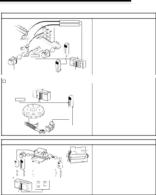
1 PRODUCT OUTLINE
MELSEC-Q
 Lifter (Storage of Braun tubes onto aging rack)
|
|
|
|
|
|
|
|
|
|
|
|
|
|
|
|
|
|
|
|
|
Unloader |
|
||
|
|
|
|
|
|
|
|
|
|
|
|
|
|
|
|
|
|
|
|
|
|
|
|
|
|
|
|
|
|
|
|
|
|
|
|
|
|
|
|
|
|
|
|
|
Loader/unloader |
||||
|
|
|
|
|
|
|
|
|
|
|
|
|
|
|
|
|
|
|
|
|
|
|
|
|
|
|
|
|
|
|
|
|
|
|
|
|
|
|
|
|
|
|
|
|
|
|
|
|
|
|
|
|
|
|
|
|
|
|
|
|
|
|
|
|
|
|
|
|
|
|
|
|
|
|
|
|
|
|
|
|
|
|
|
|
|
|
|
|
|
|
|
|
|
|
|
|
|
|
|
|
B conveyor |
|
|
|
|
|
|
|
|
|
|
|
Aging rack |
|||||||||||
|
Lifter |
|
|
|
|
|
|
|
|
|
|
|
|
|
|
|||||||||
|
|
|
|
|
|
|
|
|
|
|
|
|
|
|
|
|
|
|
|
|
|
|||
|
|
|
|
|
|
|
|
|
|
|
|
|
|
|
|
|
|
|
|
|
||||
|
|
|
|
|
|
|
|
|
|
|
|
|
|
|
|
|
|
|
|
|
|
|
|
|
|
|
|
|
|
|
|
|
|
|
|
|
|
|
|
|
|
|
|
|
|
||||
Counter- |
|
|
|
|
|
|
|
C conveyor |
|
|
|
|
|
|
|
|
||||||||
|
|
|
|
A conveyor |
|
|
|
|
|
|
|
|
Servo |
|||||||||||
weight |
|
|
|
|
|
|
|
|
|
|
|
|
||||||||||||
|
|
|
|
|
|
|
|
|
|
|
|
|
|
|
|
|
|
|||||||
Reduction |
|
|
|
|
|
|
|
|
|
|
|
|
|
G2 |
|
|
amplifier |
|||||||
|
|
|
|
|
|
|
|
|
|
|
|
|
|
|
||||||||||
|
|
|
|
|
|
|
|
|
|
|
|
|
|
|
|
|
|
|||||||
|
|
|
|
|
|
|
|
|
|
|
|
|
|
|
|
|
|
|
|
|
||||
gears |
|
|
|
|
|
|
|
|
|
|
|
|
|
|
|
|
|
|
QD75MH |
|||||
|
|
|
|
Loader |
|
|
|
|
|
Servomotor |
|
|
||||||||||||
|
G1 |
|
|
|
|
|
|
|
|
|
|
|||||||||||||
|
|
|
|
|
|
|
Servo |
|
|
|
|
|
||||||||||||
|
Servomotor |
|
|
|
|
|
|
|
|
|
|
|
||||||||||||
|
|
|
|
|
|
|
|
|
|
|
|
|||||||||||||
|
|
|
|
|
|
|
amplifier |
|
|
|
|
|
||||||||||||
|
(with brakes) |
|
|
|
|
|
|
|
|
|
|
|
||||||||||||
|
|
|
|
|
|
|
|
|
|
|
|
|
|
|
|
|
|
|||||||
•During the aging process of Braun tubes, storage onto the rack is carried out by positioning with the AC servo.
•The up/down positioning of the lifter is carried out with the 1-axis servo, and the horizontal position of the aging rack is positioned with the 2-axis servo.
|
|
|
|
|
|
|
|
|
|
|
|
|
PLC MELSEC-Q |
|
|
|
|
|
|
|
|
|
|
|
|
|
|
|
|
|
|
|
|
|
|
|
|
|
|
|
|
|
|
Index table (High-accuracy indexing of angle) |
|||||||||||
|
|
||||||||||||
|
|
|
|
|
|
|
|
|
|
||||
|
|
|
|
|
PLC |
|
QD75MH |
• The index table is positioned at a high accuracy |
|||||
|
|
|
|
|
MELSEC-Q |
|
|
using the 1-axis servo. |
|||||
|
|
Digital switch |
|
|
Servo |
||||||||
|
|
|
|
||||||||||
|
|
|
|
amplifier |
|||||||||
|
|
|
|
|
|
|
|
|
|
|
|
|
|
|
|
|
|
|
|
|
|
|
|
|
|
|
|
|
|
|
|
|
|
|
|
|
|
|
|
|
|
|
|
Index table |
|
|
|
||||||||
|
|
|
|
|
|
|
|
|
|
|
|
|
|
|
|
|
|
|
|
|
|
|
|
|
|
|
|
|
|
|
|
|
|
|
|
|
|
|
|
|
|
|
|
|
|
|
|
|
|
|
|
|
|
Detector |
Worm gears |
|
|
|
|
|
|
|
|
|
|
|
|
|
|
|
Servomotor |
||||||||||
 Inner surface grinder
|
|
Servomotor |
|
|
|
|
|
|
|
|
|
|
|
|
|
|
|
|
|
||||||||
|
|
Motor |
|
|
Workpiece |
|
|
|
|
|
|
|
|
|
|||||||||||||
|
|
|
|
|
|
|
|
|
|
|
|
|
|
|
|
|
|
|
|
|
|
|
|
|
|
||
|
|
|
|
|
|
|
|
|
|
|
IM |
|
|
|
|
|
|
|
|
|
|
|
|
|
|||
|
|
|
|
|
|
|
|
|
G |
|
|
G |
|
|
Grinding stone |
|
|
|
|
|
|
||||||
|
|
|
|
|
|
|
|
|
|
|
|
|
|
|
|
|
|
Motor |
|
|
|
|
|
|
|
||
|
Inverter |
|
|
|
|
|
|
|
|
|
|
|
|
|
|
G |
|
|
|
|
|
|
|
||||
|
|
|
|
Servo |
|
|
|
|
|
|
|
IM |
|
|
|
|
|
|
|||||||||
|
|
|
|
|
|
|
|
|
|
|
|
|
|
|
|
|
|
|
|
|
|
|
|
|
|
||
|
|
|
|
|
|
|
|
|
amplifier |
|
|
|
|
|
|
|
|
|
Inverter |
||||||||
|
|
|
|
|
|
|
|
|
|
|
Fix the grinding |
|
|
|
|
|
|
|
|
|
|
||||||
220VAC |
|
|
|
|
|
|
|
|
|
|
|
|
|
|
|
||||||||||||
|
|
|
|
stone, feed the |
|
|
|
|
|
|
|
|
|
|
|||||||||||||
60Hz |
|
|
|
|
|
|
|
|
|
|
|
|
|
|
|
|
|
|
|
||||||||
|
|
|
|
|
|
|
|
|
workpiece, and grind. |
|
|
|
|
|
|
|
|
|
|||||||||
|
|
|
|
|
|
|
|
|
|
|
|
|
|
|
|
|
|
|
|
||||||||
|
|
|
|
|
|
|
|
|
|
|
|
|
|
|
|
|
|
|
|
||||||||
|
|
|
|
|
|
|
|
|
|
|
Operation panel |
|
|
|
|
|
|
|
|
|
|||||||
|
|
|
|
|
|
|
|
|
|
|
|
|
|
|
|
|
|
a. Total feed |
d. Rough grind- |
||||||||
|
|
|
|
|
|
|
|
|
|
|
|
|
|
|
a |
|
d |
||||||||||
|
|
|
|
|
|
|
|
|
|
|
|
|
|
|
|
amount ( m) |
ing speed ( m/s) |
||||||||||
|
|
|
|
|
|
|
|
|
|
|
|
|
|
|
b |
|
e |
b. Finishing |
e. Fine grinding |
||||||||
PLC |
|
|
|
|
|
|
|
|
|
|
|
|
|
feed amount ( m) |
speed ( m/s) |
||||||||||||
|
|
|
|
|
|
c |
|
|
c. Compensation |
|
|
|
|
|
|
||||||||||||
|
|
|
|
|
|
|
|
|
|
|
|
|
|
|
|
|
|||||||||||
MELSEC-Q |
|
|
|
|
|
|
|
|
|
amount ( m) |
|
|
|
|
|
|
|||||||||||
|
|
|
|
|
|
|
|
|
|
|
|
|
|||||||||||||||
QD75MH
•The grinding of the workpiece's inner surface is controlled with the servo and inverter.
•The rotation of the workpiece is controlled with the 1-axis inverter, and the rotation of the grinding stone is controlled with the 2-axis inverter. The workpiece is fed and ground with the 3-axis servo.
1 - 6
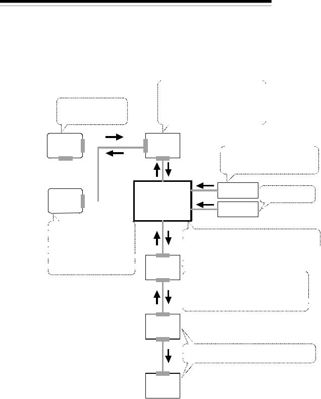
1 PRODUCT OUTLINE
1.1.3 Mechanism of positioning control
MELSEC-Q
In the positioning system using the QD75MH, various software and devices are used for the following roles. The QD75MH realizes complicated positioning control when it reads in various signals, parameters and data and is controlled with the PLC CPU.
Creates control order and conditions as a sequence program.
Stores the created program.
The QD75MH outputs the start signal and  stop signal following the stored program.
QD75MH errors, etc., are detected.
GX Developer  PLC CPU
 Outputs signals such as the start
signal, forced stop input signal, stop
signal, limit signal and control changeover signal to the QD75MH.
GX Configurator  -QP
-QP
 Sets the parameters and
 positioning data for control.
 Outputs the start command for
 JOG operation, etc., during test
 operation with the test mode.
 Monitors the positioning operation.
|
|
|
|
|
|
External signal Issues commands by |
|
|
|
|
|
|
|
|
|
|
|
|
|
|
QD75MH positioning |
|
|
|
transmitting pulses. |
||
|
|
|||||
module |
|
|
|
Manual pulse |
||
|
|
|||||
|
|
|
|
|
|
generator |
|
|
|
|
|
|
|
|
|
|
|
|
|
|
|
|
|
|
|
|
|
 Stores the parameter and data.
 Outputs datas to the servo according to the
 instructions from the PLC CPU, GX Configurator-QP,
 external signals and manual pulse generator.
  Servo
Servo 


 amplifier


 Receives positioning commands and control
 commands from QD75MH, and drives the motor.
 Outputs the positioning data of the motor
 data and etc., and external input signal of the
 servo amplifier to the QD75MH by the SSCNET
  .
.
Motor
 Carries out the actual work according to commands
  from the servo.
Workpiece
(Note): For QD75MH1, 2 and 4, use SW2D5C-QD75P (Version 2.21X) or later of the GX Configurator.
1 - 7
Loading...