

Page 1
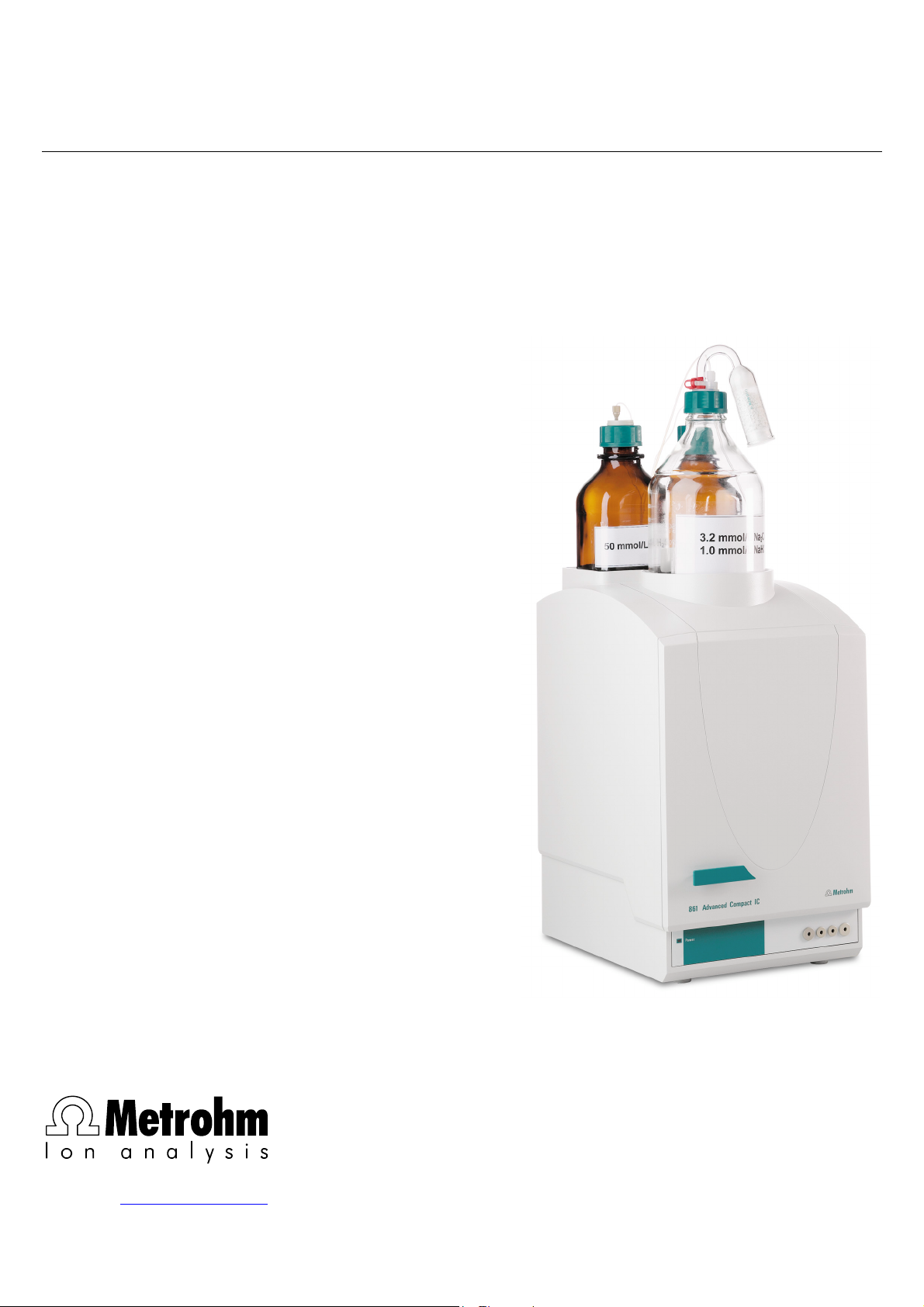
861 Advanced Compact IC
CH-9101 Herisau/Switzerland
E-Mail info@metrohm.com
Internet www.metrohm.com
Instructions for Use
8.861.1033
Page 2

Page 3
CH-9101 Herisau/Switzerland
E-Mail info@metrohm.com
Internet www.metrohm.com
861 Advanced Compact IC
8.861.1033 Instructions for Use
8.861.1033 05.2005 / chs
Page 4

Teachware
Metrohm AG
Oberdorfstrasse 68
CH-9101 Herisau
teachware@metrohm.com
1. Edition 2005
These instructions are protected by copyright. All rights reserved.
Although all the information given in these instructions has been checked with great care, errors
cannot be entirely excluded. Should you notice any mistakes please inform the author at the
address given above.
Page 5

Table of contents
Table of contents
1 Introduction ................................................................ 1
1.1 Instrument description ................................................................................1
1.2 Parts and controls .......................................................................................3
1.2.1 Front.................................................................................................................... 3
1.2.2 Rear panel .......................................................................................................... 4
1.2.3 Interior 2.861.0010.............................................................................................. 5
1.2.4 Interior 2.861.0020.............................................................................................. 7
1.2.5 Interior 2.861.0040.............................................................................................. 9
1.3 Information on the Instructions for Use...................................................11
1.3.1 Organization .....................................................................................................11
1.3.2 Notation and pictograms.................................................................................. 12
1.4 Safety notes ...............................................................................................13
1.4.1 Electrical safety................................................................................................. 13
1.4.2 General precautionary rules ............................................................................. 13
2 Installation ............................................................... 14
2.1 Overview ....................................................................................................14
2.1.1 Flow chart ......................................................................................................... 14
2.1.2 Connections in the 861 Advanced Compact IC .............................................. 14
2.2 Setting up the instrument..........................................................................16
2.2.1 Packaging.........................................................................................................16
2.2.2 Check................................................................................................................ 16
2.2.3 Location ............................................................................................................ 16
2.3 Attaching the accessories.........................................................................17
2.3.1 Connection of detector block........................................................................... 17
2.3.2 Connection of syringe and aspirating tubing...................................................18
2.3.3 Connection of the drain tube for the inner compartment ................................ 18
2.3.4 Connection of the drain tube for bottle rack ....................................................18
2.3.5 Connection of PEEK capillaries........................................................................ 18
2.3.6 Filter unit PEEK ................................................................................................. 19
2.4 Mains connection ......................................................................................21
2.4.1 Setting the mains voltage................................................................................. 21
2.4.2 Fuses ................................................................................................................ 22
2.4.3 Mains cable and mains connection ................................................................. 22
2.4.4 On/off switching of the instrument ...................................................................22
2.5 Connection to PC ......................................................................................23
2.5.1 Connecting cable .............................................................................................23
2.5.2 Software installation.......................................................................................... 23
2.5.3 First Login ......................................................................................................... 24
2.5.4 Create a system ............................................................................................... 24
2.6 High-pressure pump .................................................................................25
2.6.1 Removing the transport security screws.......................................................... 25
2.6.2 Installing the pulsation dampener.................................................................... 25
2.6.3 Connecting the eluent bottle ............................................................................ 26
2.6.4 Deaerating the pump and rinsing the pulsation dampener............................. 28
2.7 Precolumns and separating columns ......................................................30
2.7.1 Precolumns....................................................................................................... 30
2.7.2 General information on separating columns ................................................... 31
2.7.3 Selecting the sample loop................................................................................ 31
2.7.4 Installation of the separating column without suppressor module «MSM II» .. 32
2.7.5 Installation of the separating column with suppressor module «MSM II» ....... 33
861 Advanced Compact IC / Instructions for Use 8.861.1033
I
Page 6

Table of contents
2.8 Suppressor module «MSM II» ...................................................................34
2.8.1 General information on suppressor module «MSM II» .................................... 34
2.8.2 Preparation of the peristaltic pump.................................................................. 35
2.8.3 Connection of supply bottles ........................................................................... 38
2.8.4 Connection of the suppressor module «MSM II»............................................. 40
2.9 853 CO2 Suppressor..................................................................................42
2.9.1 853 CO2 Suppressor - Installation ................................................................... 42
2.9.2 853 CO2 Suppressor – Mains connection ....................................................... 42
2.9.3 853 CO2 Suppressor – Connection to 861 ...................................................... 42
2.9.4 853 CO2 Suppressor – Tubing connection...................................................... 43
2.10 Putting into operation................................................................................43
2.10.1 Putting into operation without suppressor module «MSM II» .......................... 43
2.10.2 Putting into operation with suppressor module «MSM II» ............................... 45
2.11 Connection of external devices ................................................................48
2.11.1 Connection of the 838 Advanced Sample Processor ..................................... 48
2.11.2 Connection of the 813 Compact Autosampler ................................................ 50
3 Operation .................................................................. 53
3.1 «IC Net» - Terms.........................................................................................53
3.2 Measuring operation .................................................................................53
3.2.1 Opening a system ............................................................................................ 53
3.2.2 Connect a system ............................................................................................ 54
3.2.3 Instrument icon................................................................................................. 54
3.2.4 Hardware start/stop and baseline recording ................................................... 55
3.2.5 Determination start/stop................................................................................... 55
3.3 Settings ......................................................................................................56
3.3.1 Instrument control for connected system ........................................................ 56
3.3.2 Hardware settings ............................................................................................ 62
4 Notes - Maintenance - Faults ................................... 66
4.1 Practical notes on ion chromatography ...................................................66
4.1.1 Separating columns ......................................................................................... 66
4.1.2 High-pressure pump ........................................................................................ 67
4.1.3 Eluents.............................................................................................................. 67
4.1.4 Peristaltic pump................................................................................................ 68
4.1.5 Suppressor module «MSM II» .......................................................................... 68
4.1.6 Connections ..................................................................................................... 69
4.2 Maintenance and servicing .......................................................................69
4.2.1 General information.......................................................................................... 69
4.2.2 Passivation ....................................................................................................... 70
4.2.3 Recycling.......................................................................................................... 70
4.2.4 Shutdown ......................................................................................................... 70
4.2.5 Changing separating columns......................................................................... 71
4.2.6 Maintenance work at the pump head .............................................................. 72
4.2.7 Regeneration of the suppressor module «MSM II».......................................... 76
4.2.8 Cleaning the suppressor.................................................................................. 77
4.2.9 Replacing the suppressor................................................................................ 79
4.2.10 Replacing the pump tubing ............................................................................. 80
4.3 Faults and malfunctions............................................................................82
4.3.1 Error messages ................................................................................................ 82
4.3.2 Malfunctions and their rectification .................................................................. 82
4.4 Diagnostic tests / Validation / GLP ...........................................................84
5 Appendix ................................................................... 85
5.1 Technical data............................................................................................85
II
861 Advanced Compact IC / Instructions for Use 8.861.1033
Page 7

Table of contents
5.1.1 Conductivity measurement .............................................................................. 85
5.1.2 Conductivity detector ....................................................................................... 85
5.1.3 Injection valve ................................................................................................... 86
5.1.4 High-pressure pump ........................................................................................ 86
5.1.5 Peristaltic pump................................................................................................ 87
5.1.6 Suppressor module «MSM II» .......................................................................... 87
5.1.7 Leak detector.................................................................................................... 87
5.1.8 RS232 interface ................................................................................................ 87
5.1.9 Analog output ................................................................................................... 88
5.1.10 Remote interface .............................................................................................. 88
5.1.11 Mains connection ............................................................................................. 89
5.1.12 Safety specifications......................................................................................... 89
5.1.13 Electromagnetic compatibility (EMC)............................................................... 89
5.1.14 Ambient temperature........................................................................................ 89
5.1.15 Housing ............................................................................................................ 90
5.2 Standard equipment..................................................................................91
5.3 Optional accessories ................................................................................96
5.3.1 General accessories......................................................................................... 96
5.3.2 High-pressure pump ........................................................................................ 97
5.3.3 Separating columns and precolumns.............................................................. 98
5.3.4 Column heating .............................................................................................. 100
5.3.5 Communication .............................................................................................. 101
5.4 Warranty and Conformity........................................................................102
5.4.1 Warranty.......................................................................................................... 102
5.4.2 Declaration of Conformity............................................................................... 103
5.4.3 Quality Management Principles .....................................................................104
5.5 Index.........................................................................................................105
861 Advanced Compact IC / Instructions for Use 8.861.1033
III
Page 8

Table of contents
List of figures
Figure 1: Front 861 Advanced Compact IC.............................................................. 3
Figure 2: Rear panel 861 Advanced Compact IC..................................................... 4
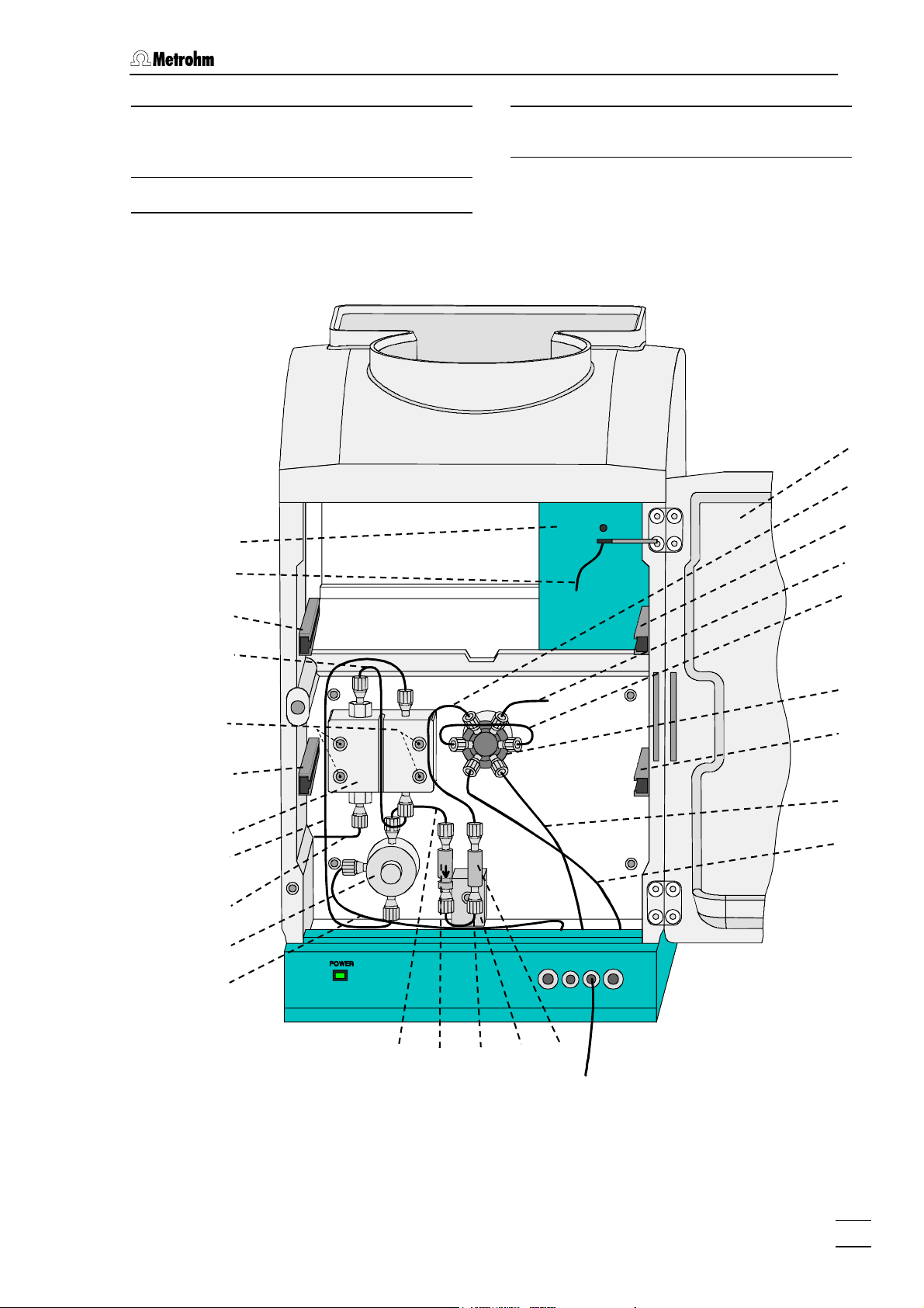
Figure 3: Interior of the IC 2.861.0010 (with permanently attached accessories
and 1.733.0110 Detector block)................................................................ 5
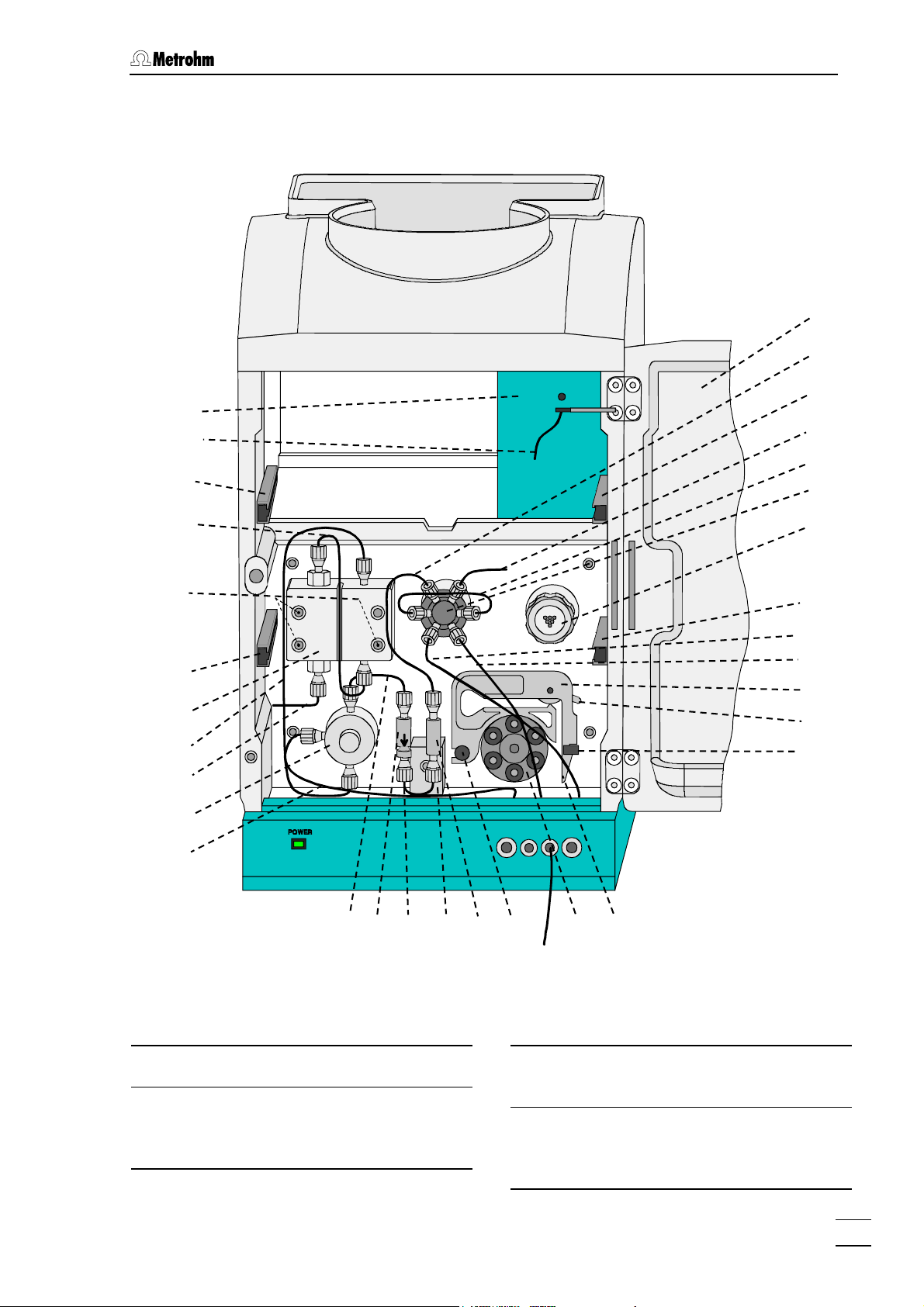
Figure 4: Interior of the IC 2.861.0020 (with permanently attached accessories,
suppressor module «MSM II» and 1.733.0110 Detector block) ................ 7
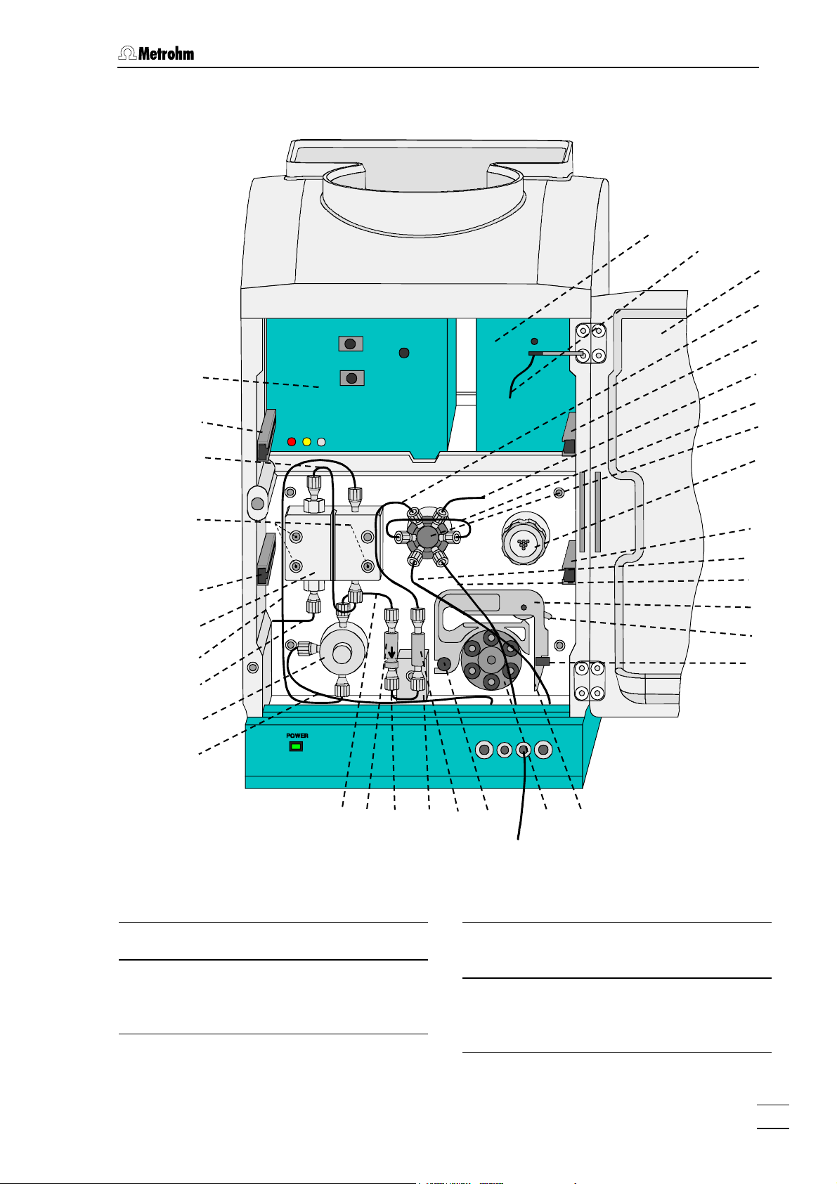
Figure 5: Interior of the IC 2.861.0040 (with permanently attached accessories,
1.733.0110 Detector block, suppressor module «MSM II» and 853 CO
Suppressor)............................................................................................... 9
Figure 6: Connecting diagram for 2.861.0010 Compact IC without suppressor ... 15
Figure 7: Connecting diagram for 2.861.0020 Compact IC with suppressor
module «MSM II» 46 ................................................................................ 15
Figure 8: Connecting diagram for 2.861.0040 Compact IC with suppressor
module «MSM II» 46 and 853 CO
Suppressor MCS 53......................... 16
2
Figure 9: Connectors for capillaries........................................................................ 19
Figure 10: 6.2821.120 Filter unit PEEK ..................................................................... 20
Figure 11: Setting the mains voltage........................................................................ 22
Figure 12: Connection of the pulsation dampener................................................... 26
Figure 13: Connection of eluent bottle ..................................................................... 28
Figure 14: Installation of column without suppressor............................................... 33
Figure 15: Installing pump tubings ........................................................................... 36
Figure 16: Connection of separation column with suppressor module «MSM II» .... 37
Figure 17: Connection of supply bottles................................................................... 40
Figure 18: Connections at suppressor module «MSM II»........................................ 41
Figure 19: Components of the pump head .............................................................. 73
Figure 20: Replacement of the piston seal 98.......................................................... 74
Figure 21: Components of inlet valve 99 and outlet valve 100 ............................... 76
Figure 22: Assembling the suppressor .................................................................... 78
2
IV
861 Advanced Compact IC / Instructions for Use 8.861.1033
Page 9

Table of contents
List of numbered parts and controls
1 Door to interior
35 Connection capillary
2 Connection purge valve
3 Connection for syringe
4 Feedthrough
5 Pilot lamp
6 Bottle rack
7 Opening
8 Opening
9 Connection for drain tube
10 Opening
11 Opening
12 Opening for detector cable
13 Knurled screw
14 Detachable rear panel
15 Transport security screws
16 Mains switch
17 Mains connection plug
36 Connection capillary
37 Purge valve
38 Aspirating capillary
39 Connection capillary
40 Pump head
41 Mounting rail
42 Fastening screws
43 Connection capillary
44 Inlet capillary for detector block
45 Detector block
46 Suppressor module «MSM II»
47 Tubing cartridge
48 Contact pressure lever
49 Holding clamp
50 Snap-action lever
51 Pump drive
18 Fuse holder
19 Serial number
20 Analog output
21 Remote interface
22 Connection for detector block
23 RS232 interface
24 Inlet capillary for injection valve
25 Mounting rail
26 Column connection capillary
27 Sample loop
28 Injection valve
29 Aspirating tubing
30 Connection capillary to syringe
31 PEEK coupling
32 Leak detector
33 Connection capillary
52 Mounting pin
53 853 CO
Suppressor
2
54 Compression fitting
55 Compression fitting
56 Capillary
57 Filter-Screw of Filter Unit
58 Filter
59 Filter-Housing of Filter Unit
60 Pulsation dampener
61 Connection to injection valve
62 Connection to purge valve
63 Aspirating tubing
64 Tubing nipple
65 Threaded stopper
66 Bottle attachment
67 Eluent bottle
34 Filter unit PEEK
861 Advanced Compact IC / Instructions for Use 8.861.1033
68 Aspirating filter
V
Page 10

Table of contents
69 CO2 absorber
70 Cotton wool
71 SGJ clip
72 Absorber tube
73 Separating column
74 Column holder
75 Aspirating tubing for H
76 Aspirating tubing for H
O
2
2SO4
77 Coupling
78 Pump tubing (6.1826.110) for H
79 Pump tubing (6.1826.110) for H
2SO4
O
2
80 Stopper (orange-yellow)
81 PEEK Coupling with filter and tubing
security device
82 Suppressor inlet capillary for eluent
83 Suppressor outlet capillary for eluent
105 Sealing ring
106 Sleeve
107 Sapphire sleeve
108 Sapphire sphere
109 Ceramic holder for sapphire sphere
110 Seal
111 Screw nut
112 Connection piece
113 Suppressor rotor
114 Suppressor holder
115 Slot in the suppressor holder
84 Suppressor inlet capillary for H
85 Suppressor inlet capillary for H
86 Suppressor outlet capillary for H
87 Suppressor outlet capillary for H
88 Bottle attachment
89 Supply bottle
90 Screw for piston cartridge
91 Zircon piston
92 Spring retainer
93 Spring
94 Piston cartridge
95 Piston guide sleeve
96 Sapphire supporting ring
97 Sapphire supporting ring
98 Piston seal
99 Inlet valve
O
2
2SO4
O
2
2SO4
100 Outlet valve
101 Screw holder
102 Special tool
103 Special tool
104 Valve housing
VI
861 Advanced Compact IC / Instructions for Use 8.861.1033
Page 11

1.1 Instrument description
1 Introduction
1.1 Instrument description
The 861 Advanced Compact IC is a PC-controlled system for ion
chromatographic analyses. The three following versions are available:
• 2.861.0010 without suppressor
• 2.861.0020 with suppressor module «MSM II»
• 2.861.0040 with suppressor module «MSM II»
and 853 CO
The extremely compact housing of the 861 Advanced Compact IC contains everything needed to carry out ion chromatography at the highest
quality level:
• Injection valve – for individual injections or for use with a sample
changer such as the Metrohm 838 Advanced Sample Processor
Suppressor (MCS)
2
• High-pressure pump – extremely low-pulsation double piston
pump with a flow range from 0.2 … 2.5 mL/min and a maximum
pressure of 35 MPa (350 bar)
• Pulsation dampener – even with low-level pressure variations the
pulsation dampener reliably protects the column against damage
• Column chamber – the perfect insulation of the housing provides
not only thermally stable conditions for the separation column but
also shields the system against electromagnetic interference
• Columns – whether anion columns with or without suppression,
separation columns for cations or organic acids – the 861 Advanced Compact IC can accommodate them all
• Suppressor module – the Metrohm suppressor module (MSM) is
already integrated in the versions 2.861.0020 and 2.861.0040 –
pressure-resistant, with fully automatic regeneration, highest performance and optimal reproducibility
• Peristaltic pump – integrated two-channel peristaltic pump with a
flow rate of 0.4 … 0.5 mL/min for regeneration and rinsing of the
suppressor module «MSM II» built into the versions 2.861.0020 and
2.861.0040.
• Detector – conductivity detector with outstanding temperature
stability. The detector temperature varies by less than 0.01°C and
can be optimally adapted to the ambient conditions.
• 853 CO
pressor (MCS) is built in downline from the suppressor module
«MSM II». The·853 CO
the eluent. This reduces the background conductivity, improves detection sensitivity and minimizes the injection and carbonate peak.
861 Advanced Compact IC / Instructions for Use 8.861.1033
Suppressor – in Version 2.861.0040 the 853 CO2 Sup-
2
Suppressor (MCS) removes the CO2 from
2
1
Page 12

1 Introduction
All components which come into contact with eluent and sample
are metal-free.
The operation of the 861 Advanced Compact IC takes place via a PC
connected to the RS232 interface with the help of the «IC Net» control
and evaluation program. This PC program can be used to create systems for recording and evaluating chromatograms. Time programs can
also be created in which a large number of instrument functions can be
triggered for each program step. It is also possible to use programmable signals to control external instruments via the remote interface.
The «IC Net» operating software meets all the requirements you could
place today on a modern integration software: single or multi-point calibration, internal or external standard, selectable algorithms for non-linear calibration, various integration modes with integration parameters
and integration events, different methods for peak recognition, peak
editor, free scaling, superimposing several chromatograms, use of
sample tables and batch reprocessing; a powerful and GLP-conform
report generator with output interfaces for monitor, printer and external
databases.
The independent «Autodatabase» PC program supplied can be used to
save and handle results and chromatograms produced by the «IC Net»
program in a database. With «Autodatabase» data can be sorted, filtered and searched with the help of different criteria. In addition, data
and curves can be printed out according to user-defined report templates.
The «IC Net» software can be configured and used in order to comply
with the Electronic Records and Signatures Rule, known as 21 CFR
Part 11, established by the U.S. Food and Drug Administration (FDA).
For this purpose the program contains password protection, user administration, electronic signatures, audit trail and administration of methods and results in databases. To use the 21 CFR Part 11 features of
«IC Net» the operating system Windows 2000 or Windows XP with
NTFS file system is required.
2
861 Advanced Compact IC / Instructions for Use 8.861.1033
Page 13
1.2 Parts and controls
1.2 Parts and controls
In this Section you will find the numbers and designations of the parts
and controls of the 861 Advanced Compact IC. The numbering applies throughout the Instructions for Use, i.e. bold numbers in the text
3
(e.g.
1.2.1 Front
6
) refer to the parts and controls illustrated here.
1
5
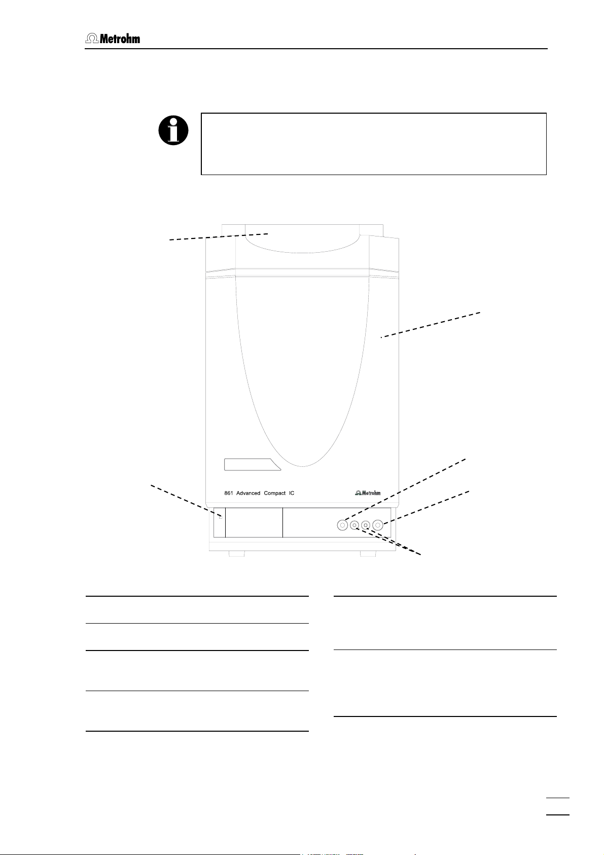
Figure 1: Front 861 Advanced Compact IC
Door to inner compartment
1
Connection purge valve
2
Connection for 6.2816.020 syringe
3
for aspiration of the sample
Feedthrough
4
for capillaries
2
3
4
Pilot lamp
5
is on when the instrument is switched
on
Bottle rack
6
for holding supply bottles with eluent,
regeneration solution, and rinsing solution
861 Advanced Compact IC / Instructions for Use 8.861.1033
3
Page 14
1 Introduction
1.2.2 Rear panel
12
13
19
20
21
7
8
9
10
11
13
14
15
16
17
18
22
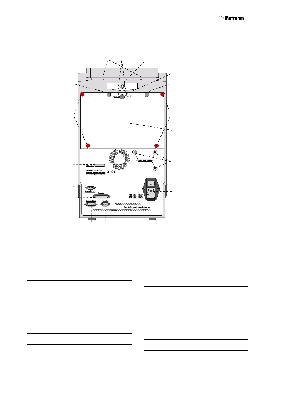
Figure 2: Rear panel 861 Advanced Compact IC
Opening
7
for in- and outlets
Opening
8
for in- and outlets
Connection for drain tube
9
for discharge of spilled liquid from the
bottle rack
Opening
10
for in- and outlets
Opening
11
for in- and outlets
Opening for detector cable
12
Knurled screw
13
for fastening the rear panel
23
Detachable rear panel
14
Access to the inner compartment
Transport security screws
15
to secure the pump head when the instrument is transported
Mains switch
16
to switch instrument on and off:
I = ON 0 = OFF
Mains connection plug
17
Mains connection, see Section 2.4
Fuse holder
18
Changing the fuses, see Section 2.4.2
Serial number
19
Analog output
20
output for analogue signal
4
861 Advanced Compact IC / Instructions for Use 8.861.1033
Page 15
1.2 Parts and controls
Remote interface
21
Remote-I/O lines for connection of external devices
Connection for detector block
22
1.2.3 Interior 2.861.0010
45
44
41
RS232 interface
23
PC connection
1
24
25
26
27
43
42
41
40
39
38
37
36
28
25
29
30
3435
313233
Figure 3: Interior of the IC 2.861.0010 (with permanently attached accesso-
ries and 1.733.0110 Detector block)
861 Advanced Compact IC / Instructions for Use 8.861.1033
5
Page 16

1 Introduction
1 Door to inner compartment
Inlet capillary for injection valve
24
PEEK capillary 6.1831.010,
length L = 24 cm
Mounting rail
25
for 6.2027.0X0 column holder
Column connection capillary
26
6.1831.010 PEEK capillary,
length L = 30 cm
Sample loop
27
20 µL PEEK sample loop 6.1825.210
Injection valve
28
Aspirating tubing
29
for sample;
PTFE-tubing 6.1803.020,
length L = 52 cm
Connection capillary
35
6.1831.010 PEEK capillary,
length L = 13 cm
Connection capillary
36
6.1831.010 PEEK capillary,
length L = 15 cm
Purge valve
37
Aspirating capillary
38
Connection for 6.1834.010 aspirating
tubing
Connection capillary
39
Connection pump head – purge
valve, fixed mounting
Pump head (6.2824.100)
40
Mounting rail
41
for cartridge holder
Connection capillary to syringe
30
6.1803.020 PTFE tubing,
length L = 30 cm
PEEK coupling (6.2744.040)
31
Leak detector
32
Connection capillary
33
6.1831.010 PEEK capillary,
length L = 13 cm
Filter unit PEEK (6.2821.120)
34
Fastening screws
42
for pump head 40
Connection capillary
43
in pump head, fixed mounting
Inlet capillary for detector block
44
PEEK capillary, fixed mounting
Detector block (1.732.0110)
45
6
861 Advanced Compact IC / Instructions for Use 8.861.1033
Page 17
1.2 Parts and controls
1.2.4 Interior 2.861.0020
1
24
25
45
44
41
26
27
28
43
42
41
40
39
38
37
36
35
46
25
30
29
47
48
49
323334
31
52
51
50
Figure 4: Interior of the IC 2.861.0020 (with permanently attached accesso-
ries, suppressor module «MSM II» and 1.733.0110 Detector
block)
1 Door to inner compartment
24 Inlet capillary for injection valve
PEEK capillary 6.1831.010,
length L = 24 cm
861 Advanced Compact IC / Instructions for Use 8.861.1033
25 Mounting rail
for 6.2027.0X0 column holder
26 Column connection capillary
6.1831.010 PEEK capillary,
length L = 30 cm
7
Page 18

1 Introduction
27 Sample loop
20 µL PEEK sample loop 6.1825.210
28 Injection valve
29 Aspirating tubing
for sample;
PTFE-tubing 6.1803.020,
length L = 52 cm
30 Connection capillary to syringe
6.1803.020 PTFE tubing,
length L = 30 cm
31 PEEK coupling (6.2744.040)
32 Leak detector
33 Connection capillary
6.1831.010 PEEK capillary,
length L = 13 cm
34 Filter unit PEEK (6.2821.120)
41 Mounting rail
for cartridge holder
42 Fastening screws
for pump head 40
43 Connection capillary
in pump head, fixed mounting
44 Inlet capillary for detector block
PEEK capillary, fixed mounting
45 Detector block (1.732.0110)
Suppressor module «MSM II»
46
(inlet and outlet capillaries are not
shown)
Tubing cartridge (6.2755.000)
47
for 6.1826.110 pump tubing
Contact pressure lever
48
for adjusting the contact pressure
35 Connection capillary
6.1831.010 PEEK capillary,
length L = 13 cm
36 Connection capillary
6.1831.010 PEEK capillary,
length L = 15 cm
37 Purge valve
38 Aspirating capillary
Connection for 6.1834.010 aspirating
tubing
39 Connection capillary
Connection pump head – purge
valve, fixed mounting
40 Pump head (6.2824.100)
Holding clamp
49
for locking the tubing cartridge into
place
Snap-action lever
50
for releasing the tubing cartridge
Pump drive
51
roller head with contact rollers
Mounting pin
52
for attaching the tubing cartridges
8
861 Advanced Compact IC / Instructions for Use 8.861.1033
Page 19
1.2 Parts and controls
1.2.5 Interior 2.861.0040
45
44
1
24
25
53
41
43
42
41
40
39
38
37
36
26
27
28
46
25
30
29
47
48
49
35
Figure 5: Interior of the IC 2.861.0040 (with permanently attached accesso-
ries, 1.733.0110 Detector block, suppressor module «MSM II» and
853 CO
Suppressor)
2
1 Door to inner compartment
24 Inlet capillary for injection valve
PEEK capillary 6.1831.010,
length L = 24 cm
861 Advanced Compact IC / Instructions for Use 8.861.1033
323334
31
52
51
50
25 Mounting rail
for 6.2027.0X0 column holder
26 Column connection capillary
6.1831.010 PEEK capillary,
length L = 30 cm
9
Page 20

1 Introduction
27 Sample loop
20 µL PEEK sample loop 6.1825.210
28 Injection valve
29 Aspirating tubing
for sample;
PTFE-tubing 6.1803.020,
length L = 52 cm
30 Connection capillary to syringe
6.1803.020 PTFE tubing,
length L = 30 cm
31 PEEK coupling (6.2744.040)
32 Leak detector
33 Connection capillary
6.1831.010 PEEK capillary,
length L = 13 cm
34 Filter unit PEEK (6.2821.120)
41 Mounting rail
for cartridge holder
42 Fastening screws
for pump head 40
43 Connection capillary
in pump head, fixed mounting
44 Inlet capillary for detector block
PEEK capillary, fixed mounting
45 Detector block (1.732.0110)
46 Suppressor module «MSM II»
(inlet and outlet capillaries are not
shown)
47 Tubing cartridge (6.2755.000)
for 6.1826.110 pump tubing
48 Contact pressure lever
for adjusting the contact pressure
35 Connection capillary
6.1831.010 PEEK capillary,
length L = 13 cm
36 Connection capillary
6.1831.010 PEEK capillary,
length L = 15 cm
37 Purge valve
38 Aspirating capillary
Connection for 6.1834.010 aspirating
tubing
39 Connection capillary
Connection pump head – purge
valve, fixed mounting
40 Pump head (6.2824.100)
49 Holding clamp
for locking the tubing cartridge into
place
50 Snap-action lever
for releasing the tubing cartridge
51 Pump drive
roller head with contact rollers
52 Mounting pin
for attaching the tubing cartridges
53
853 CO
Suppressor
2
(inlet and outlet capillaries are not
shown)
10
861 Advanced Compact IC / Instructions for Use 8.861.1033
Page 21

1.3 Information on the Instructions for Use
1.3 Information on the Instructions for Use
Please read through these Instructions for Use carefully before you put
the 861 Advanced Compact IC into operation. The Instructions for Use
contain information and warnings to which the user must pay attention
in order to assure safe operation of the instrument.
1.3.1 Organization
These Instructions for Use 8.861.1033 for the 861 Advanced Compact IC provide a comprehensive overview of installation, startup procedure, operation, fault rectification and technical specifications of this
instrument. The Instructions for Use are organized as follows:
Sect. 1 Introduction
General description of instrument, parts and controls and
safety notes
Sect. 2 Installation
Installation of instrument, accessories,
and external devices
Sect. 3 Operation
Introduction to the operation using an example
Sect. 4 Notes - Maintenance - Faults
Notes on ion chromatography, maintenance, fault rectification, diagnostic tests, validation
Sect. 5 Appendix
Technical data, standard equipment, options, warranty,
declarations of conformity, index
To find the required information on the instruments, use either the Ta-
ble of contents or the Index at the back.
As a supplement to the Instructions for Use, the Metrohm Monograph
8.792.5003 "Practical Ion Chromatography" is also supplied. This
provides an introduction to the theoretical fundamentals and general information about determinations.
861 Advanced Compact IC / Instructions for Use 8.861.1033
11
Page 22
1 Introduction
1.3.2 Notation and pictograms
The following notations and pictograms (symbols) are used in these Instructions for Use:
Fill Menu item, parameter or entry
value
in the software
SYSTEM STATE Program window
in the software
<OK> Button
in the software
22 Part or control of 861
Hazard
This symbol draws attention to a
possible danger to life or of injury if
the associated directions are not
followed correctly.
Warning
This symbol draws attention to possible damage to instruments or instrument parts if the associated directions are not followed correctly.
Caution
This symbol marks important information. First read the associated directions before you continue.
Comment
This symbol marks additional information and tips.
12
861 Advanced Compact IC / Instructions for Use 8.861.1033
Page 23
1.4 Safety notes
1.4 Safety notes
1.4.1 Electrical safety
While electrical safety in the handling of the 861 Advanced Compact IC
is assured in the context of the specifications EN / IEC 61010-1 (protection class
noted:
• Mains connection
Setting of the mains voltage, checking the mains fuse and the
mains connection must be effected in accordance with the instruc-
tions in Section 2.4.
• Opening the 861 Advanced Compact IC
If the 861 Advanced Compact IC is connected to the power supply,
the instrument must not be opened nor must parts be removed from it,
otherwise there is a danger of coming into contact with components
which are live. Therefore always disconnect the instrument from all
voltage sources before you open it and ensure that the mains cable
is disconnected from mains connection
I, degree of protection IP20), the following points should be
17
!
• Protection against static charges
Electronic components are sensitive to static charging and can be
destroyed by discharges. Before you touch any of the components inside the 861 Advanced Compact IC, you should ground yourself and
any tools you are using by touching a grounded object (e.g. housing
of the instrument or a radiator) to eliminate any static charges which
exist.
1.4.2 General precautionary rules
• Handling of solvents
Check all lines of the IC system periodically for possible leaks. Follow
the relevant instructions regarding the handling of flammable and/or
toxic solvents and their disposal.
861 Advanced Compact IC / Instructions for Use 8.861.1033
13
Page 24
2 Installation
2 Installation
2.1 Overview
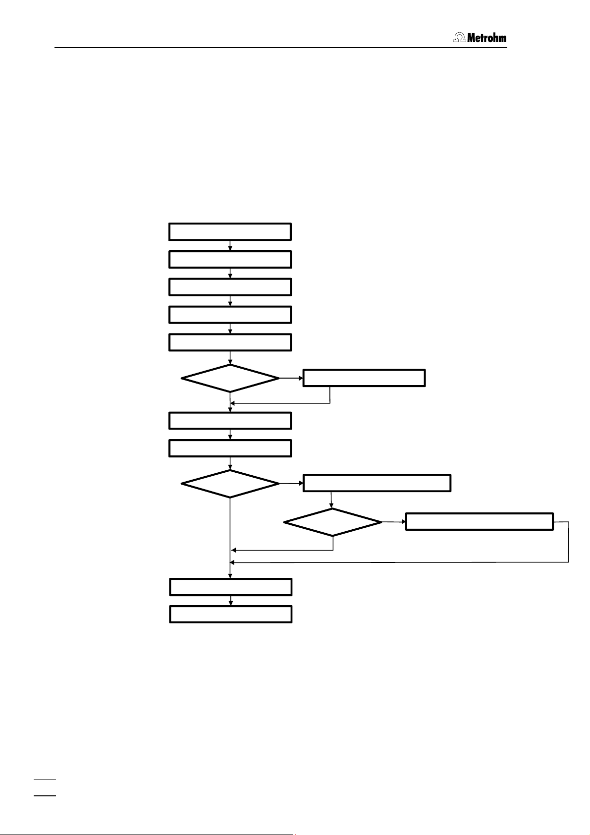
2.1.1 Flow chart
The following flow chart provides an overview of all installation work.
You will find more detailed information in the relevant Sections.
Setting up sect. 2.2
Installing accessories
Mains connection
Connecting PC sect. 2.5
Connecting high press. pump sect. 2.6
Precolumn
No
Choosing sample loop sect. 2.7.3
Connecting column sect. 2.7.4/5
Suppressor module
(MSM II)?
No
sect. 2.3
sect. 2.4
Yes
Connecting precolumn sect. 2.7.1
Yes
Connecting suppressor module (MSM II) sect. 2.8
853 CO
2
Suppressor?
No
Yes
Connecting 853 CO2 Suppressor sect. 2.9
Conditioning sect. 2.10
Connecting extern al devices sect. 2.11
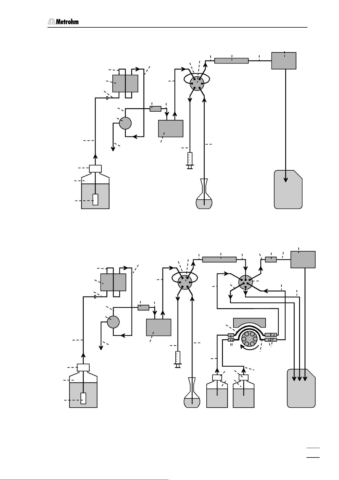
2.1.2 Connections in the 861 Advanced Compact IC
The two following illustrations show the internal connections in the 861
Advanced Compact IC in schematic form. The meanings of the various
numbered components are given in the detailed illustrations and descriptions in Sections 2.2 – 2.11.
14
861 Advanced Compact IC / Instructions for Use 8.861.1033
Page 25
2.1 Overview
66
67
68
63
40
38
43
35
37
Eluent
36
39
34
60
24
33
30
27
26
28
Injection valve
29
Sample
73
Column
44
45
Detector
Waste
66
67
63
Figure 6: Connecting diagram for 2.861.0010 Compact IC without suppres-
sor
45
31
44
Detector
39
27
28
26
73
82
83
43
40
38
34
24
33
85
87
46
84
86
35
37
78
36
60
30
29
76
77
88
81
79
75
89
68
Eluent
Figure 7: Connecting diagram for 2.861.0020 Compact IC with suppressor
module «MSM II»
861 Advanced Compact IC / Instructions for Use 8.861.1033
Sample
46
H
2SO4
H2O
Waste
15
Page 26
2 Installation
66
67
68
63
38
40
43
35
37
Eluent
36
39
34
24
33
27
28
26
85
73
87
82
83
46
53
84
44
Detector
86
45
78
60
30
29
76
77
88
81
79
75
89
Sample
H
2SO4
H2O
Waste
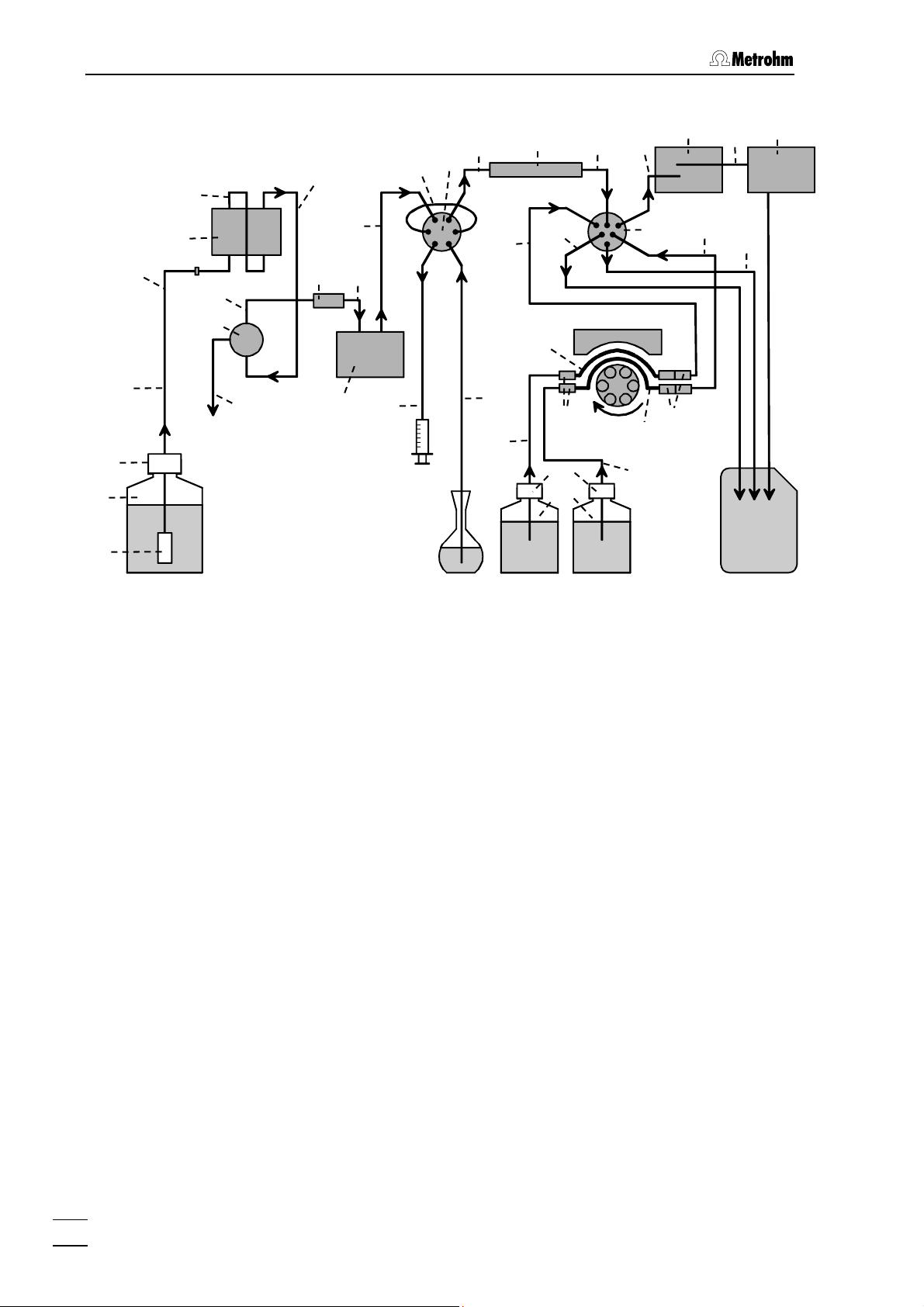
Figure 8: Connecting diagram for 2.861.0040 Compact IC with suppressor
module «MSM II»
46
and 853 CO2 Suppressor MCS 53.
2.2 Setting up the instrument
2.2.1 Packaging
The 861 Advanced Compact IC is supplied together with the separately
packed accessories in special packagings containing shock-absorbing
foam linings designed to provide excellent protection. The instrument
itself is packed in an evacuated polyethylene bag to prevent the ingress
of dust. Please store all these special packagings as only they assure
transport of the instrument free from damage.
2.2.2 Check
After receipt, immediately check whether the shipment is complete and
has arrived without damage (compare with delivery note and list of
accessories in Section 5.2). In the case of transport damage, see instructions in Section 5.4.1 "Warranty".
2.2.3 Location
Position the instrument in the laboratory at a location convenient for operation, free from vibrations and protected against a corrosive atmosphere and contamination by chemicals.
16
861 Advanced Compact IC / Instructions for Use 8.861.1033
Page 27
2.3 Attaching the accessories
To avoid disturbing temperature influences on the insulated column
compartment, the instrument must be protected against direct sunlight.
2.3 Attaching the accessories
2.3.1 Connection of detector block
The metal-free 1.732.0110 Detector block belongs to the scope of
supply of the 861 Advanced Compact IC; it must be inserted in the instrument and connected up. Proceed as follows:
If the detector block needs to be replaced then the cell constant of
the new one must be entered. On the rear of the detector block the
cell constant measured in the factory is printed on: c = XX.X /cm. This
value should be entered in the software (see Cap. 3.3.2) in order to
ensure that the conductivity is displayed accurately.
1 Install detector block
• Unscrew the four knurled screws 13 from the top rear panel
14 of the 861 Advanced Compact IC and remove rear panel
(see Figure 2)
• Position detector block 45 from the back in the space pro-
vided in the 861 Advanced Compact IC and push fully to the
front (see Figure 3, Figure 4 and Figure 5).
• Insert the cable permanently attached to the detector block
45 in one of the openings 12 and the outlet capillary in one of
the openings 8 of the rear panel 14.
You can now place the 853 CO
tector block of Version 2.861.0040 so that you do not have to
Suppressor beside the de-
2
remove the rear panel again (see Figure 5). Connecting the
853 is described in detail in Section 2.9. Pull the Remote cable and the mains cable out of opening 11 in the rear panel.
2 Replace rear panel
• Replace rear panel 14 and screw onto the 861 Advanced
Compact IC using the four knurled screws 13.
3 Connect detector block
• Plug the gray connecting cable permanently attached to the
detector block 45 into connection 22 "Detector Block" of the
861 Advanced Compact IC and fasten to the instrument by
tightening the screws in the cable connector (see Figure 2).
4 Connect waste container
• Lead the outlet capillary of the detector block 45 to a suffi-
ciently large waste container and fix in place.
861 Advanced Compact IC / Instructions for Use 8.861.1033
17
Page 28

2 Installation
2.3.2 Connection of syringe and aspirating tubing
For manual filling of the sample loops 27 mounted on the injection
valves, the 6.2816.020 Syringe and the PTFE aspirating tubing 29 already screwed to the valve are needed. These accessories are
mounted or adjusted as follows:
1 Connect syringe
• Remove the plastic stopper from connection socket 3 on the
front side of the 861 Advanced Compact IC (see Figure 1).
• Push 6.2816.020 Syringe (without needle) as far as it will go
into connection socket 3.
2 Lead aspirating tubing to the outside
• Lead the PTFE aspirating tubing 29 connected to the injec-
tion valve 28 through one of the feedthroughs 4 to the outside.
2.3.3 Connection of the drain tube for the inner compartment
The 861 Advanced Compact IC has a connection at the front to which a
drain tube for discharged liquids in the inner compartment can be attached. Proceed as follows:
1 Connect drain tube
• Mount 6.1816.020 Silicone tubing on connection nipple on
the lower right side.
2 Lead drain tube to collecting vessel
• Lead the other end of the drain tube to a suitable collecting
vessel and fix in place.
2.3.4 Connection of the drain tube for bottle rack
The 861 Advanced Compact IC has a connection at the rear to which a
drain tube for discharged liquids in the bottle rack can be attached.
Proceed as follows:
1 Connect drain tube
• Mount 6.1816.020 Silicone tubing on connection nipple 9
(see Figure 2).
2 Lead drain tube to collecting vessel
• Lead the other end of the drain tube to a suitable collecting
vessel and fix in place.
2.3.5 Connection of PEEK capillaries
For the connections between high-pressure pump and detector block
6.1831.010 PEEK capillaries (i.d. = 0.25 mm, o.d. =
which are connected using either 6.2744.010 PEEK compression fit-
tings (long) or 6.2744.070 PEEK compression fittings (short).
18
861 Advanced Compact IC / Instructions for Use 8.861.1033
1
/16") are used
Page 29
2.3 Attaching the accessories
These PEEK connectors can also be used to connect 6.1822.010 PTFE
microcapillaries (i.d. = 0.3 mm). Proceed as follows:
Capillaries fitted with new connectors must have a perfectly flat cut
surface. To cut PEEK or PTFE capillaries it is best to use the
6.2621.080 Capillary tubing cutter.
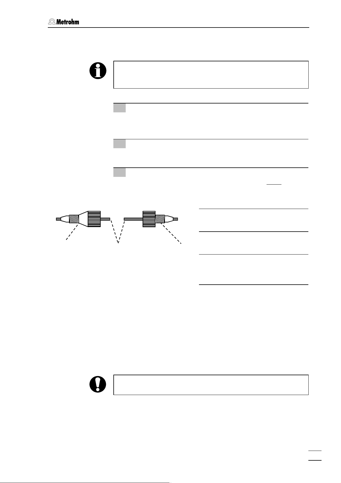
1 Mount compression fitting
• Slide a compression fitting 54 (6.2744.010) or a compression
fitting 55 (6.2744.070) over the end of the capillary 56 to be
fastened as shown in Figure 9.
2 Insert capillary in connection
• Push capillary end in the corresponding connection as far as
it will go (to avoid dead volume).
3 Tighten compression fitting
• Tighten compression fitting 54 or 55 by hand (never use
tools).
54
56
Figure 9: Connectors for capillaries
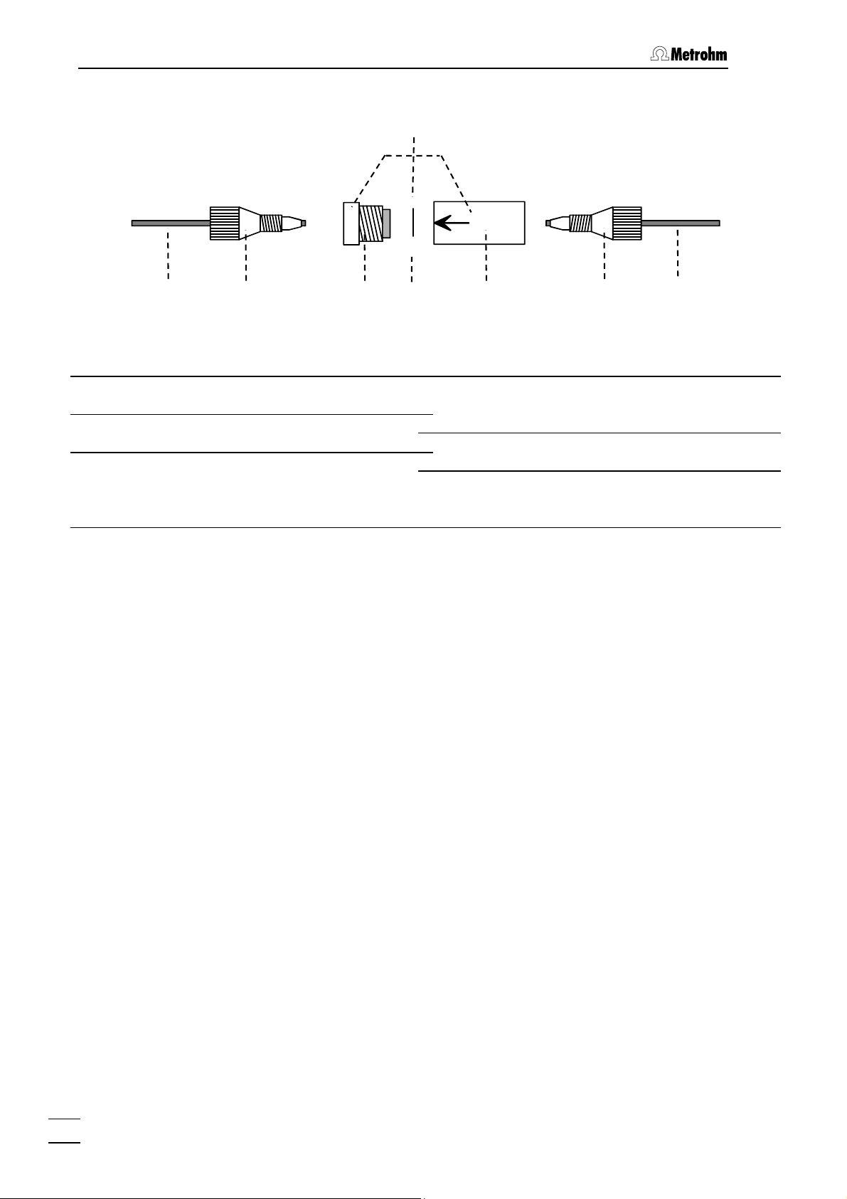
2.3.6 Filter unit PEEK
One 6.2821.120 Filter unit PEEK (see Figure 10) is installed between
the high-pressure pump and injection valve 28. This filter unit serves to
avoid contamination by abrasive particles of the piston seals.
The Filter unit PEEK 34 consists of the filter-housing 59, the filter-screw
57 and the 6.2821.130 Filter 58. For the connection of capillaries 56
PEEK compression fittings 54/55 (6.2744.010 or 6.2744.070) must be
used. New filters 58 are available as an option with the ordering number
6.2821.130 (set of 10).
When connecting the filter unit please note the flow direction arrow
printed on the housing.
55
Compression fitting
54
(6.2744.010)
Compression fitting
55
(6.2744.070)
Capillary
56
6.1831.010 PEEK capillary or
6.1822.010 PTFE microcapillary
861 Advanced Compact IC / Instructions for Use 8.861.1033
19
Page 30
2 Installation
34
56
54 57
Figure 10: 6.2821.120 Filter unit PEEK
34 Filter unit PEEK (6.2821.120)
54 Compression fitting (6.2744.010)
56 Capillary
6.1831.010 PEEK capillary or 6.1822.010
PTFE microcapillary
58
59
Filter screw of filter unit
57
54
Part of 6.2821.120 Filter unit
6.2821.130 Filter
58
Filter housing of filter unit
59
Part of 6.2821.120 Filter unit
56
20
861 Advanced Compact IC / Instructions for Use 8.861.1033
Page 31

2.4 Mains connection
2.4 Mains connection
Follow the instructions below for connecting to the power supply. If the
instrument is operated with a mains voltage set wrongly and/or wrong
mains fuse, there is a danger of fire!
2.4.1 Setting the mains voltage
Before switching on the 861 Advanced Compact IC for the first time
check that the mains voltage set on the instrument (see Figure 11)
matches the local mains voltage. If this is not
the mains voltage on the instrument as follows:
1 Disconnect mains cable
Disconnect mains cable from mains connection plug 17 of the
861 Advanced Compact IC.
the case, you must reset
2 Remove fuse holder
Using a screwdriver, loosen fuse holder 18 below the mains
connection plug 17 and take out completely.
3 Check and change fuse if necessary
Carefully take the fuse installed for the desired mains voltage out
of fuse holder 18 and check its specifications (the position of the
fuse in the fuse holder is marked by the white arrow imprinted
next to the mains voltage range):
100…120 V 1.0 A (slow-blow) Metrohm No. U.600.0016
220…240 V 0.5 A (slow-blow) Metrohm No. U.600.0013
4 Insert fuse
Change fuse if necessary and reinsert in fuse holder 18.
5 Install fuse holder
Depending on the desired mains voltage, insert fuse holder 18
in the 861 Advanced Compact IC so that the corresponding
mains voltage range can be read normally and the adjacent
white arrow points to the white bar imprinted below the fuse
holder (see Figure 11).
861 Advanced Compact IC / Instructions for Use 8.861.1033
21
Page 32

2 Installation
V
220 – 240 V
16
17
18
220 - 240 V
2.4.2 Fuses
100 – 120
16 Mains switch
to switch instrument on and off:
I = ON 0 = OFF
17 Mains connection plug
Mains connection, see Section 2.4.3
100 - 120 V
100 - 120 V
220 - 240 V
18 Fuse holder
Figure 11: Setting the mains voltage
One of the two fuses 1 A/slow-blow for 100…120 V or 0.5 A/slow-blow
for 220…240 V is installed in fuse holder 18 of the 861 Advanced Compact IC as standard.
Ensure that the instrument is never put into operation with fuses of another type, otherwise there is danger of fire!
When checking or changing fuses proceed as described in Section
2.4.1.
2.4.3 Mains cable and mains connection
Mains cable
The instrument is supplied with one of three mains cables
• 6.2122.020 with plug SEV 12 (Switzerland, …)
• 6.2122.040 with plug CEE(7), VII (Germany, …)
• 6.2133.070 with plug NEMA 5-15 (USA, …)
which are three-cored and fitted with a plug with a grounding pin. If a
different plug has to be fitted, the yellow/green lead (IEC standard)
must be connected to protective ground (protection class 1).
Any break in the grounding inside or outside the instrument can make
it a hazard!
Mains connection
Plug the mains cable into mains connection plug 17 of the 861 Advanced Compact IC (see Figure 11).
2.4.4 On/off switching of the instrument
The 861 Advanced Compact IC is switched on and off using mains
switch 16. When the instrument is switched on, the mains pilot lamp 5
lights up.
22
861 Advanced Compact IC / Instructions for Use 8.861.1033
Page 33

2.5 Connection to PC
2.5 Connection to PC
2.5.1 Connecting cable
Always switch off 861 Advanced Compact IC and PC before you connect the two instruments with the 6.2134.100 Cable.
Connect the RS232 interface 23 at the 861 Advanced Compact IC to
the serial COM1 port at the PC using the 6.2134.100 Cable (9-pin/9pin). If only a 25-pin COM interface is available on the PC then the
6.2125.110 Adapter cable or a commercially available adapter must be
used.
2.5.2 Software installation
The operation of the 861 Advanced Compact IC requires the PC program «IC Net», which is part of the 6.6034.033 CD (included in the accessories). This program runs under Windows 2000 and Windows XP
operating systems and is installed as follows:
1 Install program
• Insert the installation CD 6.6034.033 into your CD-ROM drive.
• If the autorun option for the CD drive is disabled, select
<Start> and Run. Browse for the Setup.exe file on the installa-
tion CD and click on
• Click "
IC Net" and follow the on-screen prompts of the Setup
<OK>.
program (see Instructions for Use «IC Net», Section 1.5 for a
more detailed description).
2 Files
The software package will be installed in the desired directory.
Icons are created in the program folder and in the startup folder.
In addition to the program files, the following folders are installed:
Data Folder for storage of chromatogram files
(
*.chw) and batch reprocessing files (*.bar)
Devices Folder for storage of device files (*.dev)
Excelreport Folder for Excel reports (*.xls)
Methods Folder for storage of method files (*.mtw)
Reports Folder for storage of report files (*.txt)
and graphic files (
Systems Folder with subfolders with system files
*.smt) and sample queue files (*.que).
(
*.wmf)
The installed files (incl. system and method files) are generally not
write-protected. To prevent these files from being deleted by mistake,
switch on the write-protection or make a backup copy in another directory.
861 Advanced Compact IC / Instructions for Use 8.861.1033
23
Page 34

2 Installation
2.5.3 First Login
Starting and closing of the Software is described in the provided Software Instructions for Use «IC Net», Section 2.
Add User window (see below) opens the first time you launch the
The
program after installing the software and a user with Administrator access rights is created.
2.5.4 Create a system
Create in «IC Net» a system to control the 861 Advanced Compact IC.
Proceed as described in Section 4.4.1 of the Software Instructions for
Use «IC Net»: System wizard. Add your version of the 861 Advanced
Compact IC (they are listed under "Metrohm Detectors") to the system,
and choose the port to which it is connected.
24
861 Advanced Compact IC / Instructions for Use 8.861.1033
Page 35

2.6 High-pressure pump
2.6 High-pressure pump
In order to avoid damage to the pump it must never be operated dry.
Each time that the pump is switched on always first check that the
eluent supply has been connected up correctly and that sufficient eluent is present in the eluent bottle.
2.6.1 Removing the transport security screws
In order to prevent the pump drive from being damaged during transport the pump head is fitted with three transport security screws 15 (see
Figure 2). These transport security screws must be removed before the
high-pressure pump is started up. Also remove the red sticker attached
to the pump head.
In order to avoid damage to the pump head these three security
screws should be attached to the pump head each time that the 861
Advanced Compact IC is to be transported.
2.6.2 Installing the pulsation dampener
To protect the column material against pressure drops caused by the
injection valve, the 6.2620.150 Pulsation dampener MF has to be in-
stalled between the high-pressure pump and the injection valve of the
861 Advanced Compact IC. Proceed as follows (see Figure 12):
1 Install pulsation dampener
• Position the pulsation dampener 60 in the interior of the Com-
pact IC on the base.
2 Connection to the pump
• Unscrew PEEK capillary 33 of coupling 31 and attach it to
connection 62 of the pulsation dampener 60.
3 Connection to injection valve
• Unscrew PEEK capillary 24 of coupling 31 and attach it to
connection 61 of the pulsation dampener 60.
The pulsation dampener is filled with isopropanol and must be rinsed
with eluent before connection to a separating column (see Section
2.6.4).
The 6.2620.150 Pulsation dampener can be operated in both directions.
861 Advanced Compact IC / Instructions for Use 8.861.1033
25
Page 36

2 Installation
s
24
35
37
28
34
33
62 61
Figure 12: Connection of the pulsation dampener
24 Inlet capillary for injection valve
PEEK capillary 6.1831.010,
length L = 24 cm
28 Injection valve
33 Inlet capillary for injection valve
PEEK capillary 6.1831.010,
length L = 13 cm
34 Filter unit PEEK (6.2821.120)
2.6.3 Connecting the eluent bottle
The eluent supply line from the storage bottle to the high-pressure
pump is connected as follows (see Figure 13):
60
35 Connection capillary
6.1831.010 PEEK capillary,
length L = 13 cm
37 Purge valve
Pulsation dampener (6.2620.150)
60
Connection to injection valve
61
Connection to purge valve
62
Only degassed (with N
, He or vacuum) and microfiltered (0.45 µm
2
filter) eluents should be used!
The 6.1608.070 Eluent bottle (2 L) supplied is not suitable for vacu-
um degassing. Use a pressure-resistant container for this.
Care must be taken that the eluent used is freely miscible with any
olvent remaining in the pump head (the pump head leaves the fac-
26
861 Advanced Compact IC / Instructions for Use 8.861.1033
Page 37

2.6 High-pressure pump
tory filled with either isopropanol or methanol/water). If this is not the
case then the pump must first be rinsed with a solvent which is miscible with both the previous eluent and the following eluent (e.g. acetone).
1 Prepare eluent bottle
• Prepare, microfilter (0.45 µm microfilter) and degas (with N2,
He, or vacuum) the suitable eluent for the required application and separating column.
• Fill eluent into eluent vessel 67 (clear glass, 2 L).
• Place eluent bottle 67 at the front in bottle holder 6 on the 861
Advanced Compact IC (see Figure 1).
2 Install bottle attachment
• Firmly screw threaded stopper 65 (6.1446.040; part of
6.1602.160) into the smaller threaded opening (M6) of bottle
attachment 66 (6.1602.105; part of 6.1602.160).
• Firmly screw aspirating filter 68 onto aspirating tubing 63.
• Pull the other end of aspirating tubing 63 through the larger
threaded opening (M8) of bottle attachment 66 from below.
• Push O-ring (E.301.0021; part of 6.1602.160) over the free
end of aspirating tubing 63 and move it towards bottle attachment 66.
• Push tubing nipple 64 (4.420.4300; part of 6.1602.160) over
the free end of aspirating tubing 63, move it as far as required towards bottle attachment 66 and screw it loosely in the
larger opening of bottle attachment 66.
• Insert aspirating tubing 63 with screwed-on aspiration filter 68
into eluent bottle 67 and screw bottle attachment 66 onto
eluent bottle 67.
• Pull aspirating tubing 63 so far through the opening of tubing
nipple 64 that aspirating filter 68 is touching the bottom of
eluent bottle 67.
• Fix aspirating tubing 63 in place by screwing shut tubing
nipple 64.
3 Mount CO2 absorber tube
• First place a piece of cotton wool 70 followed by CO2 ab-
sorber 69 (e.g. Merck soda lime pellets with indicator, no.
6839.1000) in the large opening of absorber tube 72 and then
close it with the plastic lid.
• Fasten absorber tube 72 to bottle attachment 66 with the aid
of SGJ clip .
4 Connect aspirating tubing to pump
• Insert the free end of aspirating tubing 63 into one of the ope-
nings 8 in the interior of the 861 Advanced Compact IC (see
Figure 2).
• Pull aspirating tubing 63 sufficiently far into the interior of the
861 Advanced Compact IC / Instructions for Use 8.861.1033
27
Page 38

2 Installation
861 Advanced Compact IC, cut off to the required length and
push at least 5 mm of it onto aspirating capillary 38 (see
Figure 3 and Figure 4 and Figure 5) of the high-pressure
pump (it may be necessary to use emery paper).
• If necessary, fix aspirating tubing 63 in the required position
in the interior with the aid of the Y.107.0150 self-adhesive
strap.
72
71
70
69
63
64
65
66
Aspirating tubing (6.1834.010)
63
Tubing nipple (4.420.4300; M8)
64
with E.301.0021 O-ring
Threaded stopper (6.1446.040; M6)
65
Bottle attachment (6.1602.105)
66
Eluent bottle (6.1608.070)
67
67
Aspirating filter (6.2821.090)
68
CO
absorber
2
Cotton wool
SGJ clip (6.2023.020)
Absorber tube (6.1609.000)
68
Figure 13: Connection of elu-
69
70
71
72
ent bottle
2.6.4 Deaerating the pump and rinsing the pulsation dampener
The first time that it is started up the high-pressure pump must be deaerated. Proceed as follows:
1 Prepare for deaeration
• Open the rotary knob on purge valve 37 by approx. ½ turn in
the counterclockwise direction (see Figure 3 and Figure 4 and
Figure 5).
• Remove the plastic stopper from connection 2 on the front
panel of 861 Advanced Compact IC (see Figure 1).
• Push 6.2816.020 Syringe (without needle) into connection 2
until the stop is reached.
2 Open and connect system
• Start the «IC Net» PC program, if it has not been already
been started (see Section 2.5.3).
• Select
tem created in Section 2.5.4, and click on
28
861 Advanced Compact IC / Instructions for Use 8.861.1033
File / Open / System in the main window. Select the sys-
<Open>.
Page 39

2.6 High-pressure pump
• Select the
Connect to workplace item of the Control menu in this
window.
3 Set flow rate to 2 mL/min
• Double-click the 861 icon in the system window to open the
window for manual control of the 861 Advanced Compact IC
(see below).
• Set the flow rate to
• Click to
<Send to unit> to send this value to the 861 Advanced
2 mL/min in the Flow field.
Compact IC.
4 Deaerate pump
• Make sure that the aspirating tubing 63 for the high-pressure
pump has been immersed into the eluent.
• Click the
sure pump.
• Use the syringe inserted into connection 2 to aspirate air until
eluent flows bubble-free into the syringe.
• Click the
861 Advanced Compact IC / Instructions for Use 8.861.1033
<On> button for IC pump to switch on the high-pres-
<Off> button for IC pump to switch off the high-pres-
29
Page 40

2 Installation
sure pump.
• Close the rotary knob on purge valve 37 by turning it in a
clockwise direction (see Figure 3 and Figure 4 and Figure 5).
• Remove the syringe from connection 2.
5 Rinse pulsation dampener
• Place a beaker beneath the column connection capillary 26.
• Click the
<On> button for IC pump to switch on the high-pres-
sure pump and rinse the pulsation dampener 60 filled with
isopropanol for approx. 10 min with eluent.
• Click the
<Off> button for IC pump to switch off the high-pres-
sure pump.
6 Reduce flow rate
• Reset the original flow rate under Flow (e.g. 0.5 mL/min).
• Click
<Send to unit> to send this value to the 861 Advanced
Compact IC.
• Click
<Save> to save the values.
2.7 Precolumns and separating columns
2.7.1 Precolumns
The use of easily exchangeable precolumns protects the separating
columns and prolongs their lifetime. The precolumns available from
Metrohm are either real precolumns or precolumn cartridges, which are
used together with a cartridge holder. For the installation of a precolumn cartridge into the accompanying cartridge holder see the attached
leaflet.
The precolumn that is suitable for your separating column can be
found in the Metrohm IC Column Catalog which can be obtained
from your local Metrohm agency, the data sheet accompanying your
separating column, the product information about separating columns
that can be found under http://www.metrohm.com
phy products, or let your agency advise you directly.
New IC precolumns are normally filled with solution and sealed at both
ends. Before the precolumn is installed in the system, it must be ensured that this solution is freely miscible with the eluent used (check
manufacturer's specifications).
, ion chromatogra-
30
861 Advanced Compact IC / Instructions for Use 8.861.1033
Page 41

2.7 Precolumns and separating columns
1 Connect precolumn
• Remove end caps from the precolumn.
• Fit compression fitting to the connection capillary 26 moun-
ted to the injection valve (see Section 2.3.5).
• Screw column connection capillary 26 to precolumn.
• Cut off a small piece, approx. 5 cm, from the 6.1831.010
PEEK capillary and fit compression fittings to both ends (see
Section 2.3.5).
• Mount the prepared capillary to the outlet of the precolumn.
When you install the column always ensure that this is inserted correctly in accordance with the flow direction (if existent) shown.
2 Rinse the precolumn
• Place a beaker beneath outlet capillary.
• Switch on IC Pump in «IC Net» and rinse precolumn for
approx. 10 min with eluent.
• Switch off IC Pump.
2.7.2 General information on separating columns
The precolumn that is suitable for your separating column can be
found in the Metrohm IC Column Catalog, the product information
about separating columns that can be found under http://www.met-
rohm.com, ion chromatography products, or let your agency advise
you directly.
New IC columns are normally supplied filled with liquid and sealed at
both ends. Before inclusion in the system you must make sure that
this solution is fully miscible with the eluent to be used (observe the information provided by the manufacturer).
The separating columns and precolumns currently available from
Metrohm can be found in the Metrohm IC Column Catalog, or on the
Internet under http://www.metrohm.com
duct section. Each column is supplied with a test chromatogram and a
data sheet. More detailed information about special IC applications can
be found in the relevant "Application Bulletins" or "Application No-
tes"; these are available on the Internet under http://www.metrohm.com
in the applications sector, or can be requested free of charge from your
local Metrohm agency.
When you install the column always ensure that this is inserted correctly in accordance with the flow direction shown.
2.7.3 Selecting the sample loop
Selection of the sample loop depends on the separating column used.
Normally the following sample loops are used:
861 Advanced Compact IC / Instructions for Use 8.861.1033
in the ion chromatography pro-
31
Page 42

2 Installation
Anion columns 100 µL
Cation columns 10 µL
Columns for suppressor technique 20 µL
The following sample loops are installed in the 861 Advanced Compact
IC:
Version Sample loop Volume
2.861.0010 6.1825.210 (PEEK) 20 µL
2.861.0020 6.1825.210 (PEEK) 20 µL
2.861.0040 6.1825.210 (PEEK) 20 µL
If desired, the built-in sample loop can be replaced by one of the sample loops available as an option (see Section 5.3.1).
2.7.4 Installation of the separating column without suppressor module «MSM II»
With the 2.861.0010 Compact IC without suppressor module «MSM II»,
the IC separating column is installed as follows (see Figure 14):
1 Connect column to injection valve
• Remove end caps from column 73.
• without precolumn:
Screw inlet end of separating column 73 (note flow direction)
to column connection capillary 26 mounted on the injection
valve.
• with precolumn:
See relevant leaflet.
2 Rinse column
• Place a beaker beneath the column outlet.
• Open software window for manual system control.
• If necessary, modify
ted separating column and click on
Flow rate to the value suited for the inser-
<Send to unit> to send this
value to the 861 Advanced Compact IC.
• Switch on high-pressure pump (
IC pump) by clicking <On>
and rinse column with eluent for approx. 10 min.
• Switch off high-pressure pump by clicking
<Off>.
3 Connect column to detector block
• Screw outlet end of separating column 73 to the inlet capillary
44 permanently mounted on the detector block 45.
4 Column attachment
• Insert one or two column holders 74 (6.2027.030, 6.2027.040
or 6.2027.050) in the mounting rails 25 and fasten separating
column 73 in the column holder 74.
32
861 Advanced Compact IC / Instructions for Use 8.861.1033
Page 43

2.7 Precolumns and separating columns
45
44
74
25
28
73
25
74
26
25 Mounting rail
for column holder 74
26 Column connection capillary
Connection injection valve 28 –
separating column 73
28 Injection valve
44 Inlet capillary for detector
block
PEEK capillary, fixed mounting
45 Detector block (1.733.0110)
Separating column
73
Column holder (6.2027.0X0)
74
Figure 14: Installation of column without suppressor
2.7.5 Installation of the separating column with suppressor module «MSM II»
With the versions 2.861.0020 and 2.861.0040 Compact IC with suppressor module «MSM II», the IC separating column is first connected to
the injection valve or precolumn. The connection to the suppressor
module «MSM II» and the detector block is described in Section 2.8.
1 Connect column to injection valve
• Remove end caps from column 73.
• Screw inlet end of separating column 73 (note flow direction)
to column connection capillary 26 or to the already installed
precolumn (procedure see Section 2.7.4).
2 Rinse column
• Place a beaker beneath the column outlet.
• Open software window for manual system control.
• If necessary, modify
ted separating column and click on
value to the 861 Advanced Compact IC.
• Switch on high-pressure pump (
and rinse column with eluent for approx. 10 min.
• Switch off high-pressure pump by clicking
Flow rate to the value suited for the inser-
<Send to unit> to send this
IC pump) by clicking <On>
<Off>.
861 Advanced Compact IC / Instructions for Use 8.861.1033
33
Page 44

2 Installation
3 Connect column to suppressor module «MSM II»
• Screw the outlet end of separating column 73 to the "Sup-
pressor inlet capillary for eluent" 82, which is permanently attached to the suppressor module «MSM II» 46.
4 Fix column
• Insert one or two column holders 74 (6.2027.030, 6.2027.040
or 6.2027.050) in the mounting rails 25 and fasten separating
column 73 in the column holder 74.
2.8 Suppressor module «MSM II»
2.8.1 General information on suppressor module «MSM II»
The suppressor module «MSM II» for chemical suppression installed
in the 2.861.0020 and 2.861.0040 Compact IC comprises a total of 3
suppressor units which are in turn used for suppression, regenerated
with sulfuric acid and rinsed with water. To record every new chromatogram under comparable conditions, work is normally carried out with
freshly regenerated suppressor. Switching is either automatic together
with the valve switching or manual.
The suppressor units must never be regenerated with H
same flow direction used for the eluent. You should thus always install
2SO4
in the
the inlet and outlet capillaries as described in Section 2.8.4 according
to the scheme shown in Figure 18.
For operation of the suppressor module «MSM II» the two-channel
peristaltic pump built into the versions 2.861.0020 and 2.861.0040 is
used which conveys the regeneration solution (normally 20 mmol/L
H
) and the rinsing solution (normally dist. H2O) to the suppressor
2SO4
units (flow rate of 0.5 mL/min).
The three inlets and outlets numbered 1...3 on the suppressor module
«MSM II» each have 2 permanently mounted PTFE capillaries, which
must be connected as described in Section 2.8.4 (see Figure 16 and
Figure 18).
In order to protect the suppressor module «MSM II» from foreign bodies
or bacterial growth a 6.2821.130 Filter 58 (forms part of "PEEK coupling
81 with filter and tubing security device" 6.2744.180) must be mounted
between the peristaltic pump and the inlet capillary of suppressor module «MSM II».
The suppressor module «MSM II» must never
be switched in the dry
state as there is a danger of blocking. Before every switching operation of the suppressor module «MSM II», the three suppressor units
must have been rinsed for at least ½ h with eluent, regeneration and
rinsing solution.
34
861 Advanced Compact IC / Instructions for Use 8.861.1033
Page 45

2.8 Suppressor module «MSM II»
2.8.2 Preparation of the peristaltic pump
Before start-up the accessories for the 2-channel peristaltic pump built
into the 861 Advanced Compact IC must be mounted according to
Figure 15. Proceed as follows:
1 Remove tubing cartridges
• Loosen both tubing cartridges 47 from the holding clamp 49
by pressing down snap-action lever 50 and remove from
mounting pin 52 (see Figure 16).
2 Insert pump tubings
• Press contact pressure lever 48 on both tubing cartridges
down as far as it will go.
• Insert the pump tubings 78 and 79 (6.1826.110) into each of
the tubing cartridges as shown in Figure 15. The orangeyellow stopper 80 must click into the corresponding holder on
the left-hand side of the tubing cartridge.
3 Attach coupling to pump tubing
• Attach PEEK coupling 77 to the aspiration end of pump tub-
ings 78 / 79 (see Figure 15).
Mount PEEK coupling 81 with filter and tubing security device
•
(6.2744.180) to the delivery end of pump tubing 78 / 79.
This is done by dismantling the tubing security device and
first pushing the sleeve nut and the compression piece onto
the tubing.
Attach the tubing to the PEEK coupling and screw the sleeve
nut onto the coupling in order to secure the tubing.
4 Attach tubing cassettes
• Hinge the tubing cassettes on holding pin 52 and press
down on the right-hand side until spring lever 50 clicks into
position in holding clip 49. Take care that the pump tubing
does not kink.
5 Connect suppressor inlet capillary
• Attach "Suppressor inlet capillary for H2O" 84 / "Suppressor
inlet capillary for H
" 85 with a compression fitting 54 to
2SO4
the Coupling 81.
861 Advanced Compact IC / Instructions for Use 8.861.1033
35
Page 46

2 Installation
54 77
75/76
78/79
80
Figure 15: Installing pump tubings
47 Tubing cartridge (6.2755.000)
48 Contact pressure lever
for adjusting the contact pressure
47 48
50
80 81
54
Pump tubing (6.1826.110) for
78
2SO4
H
Pump tubing (6.1826.110) for H
79
58
84/85
O
2
50 Snap-action lever
for releasing the tubing cartridge
54 Compression fitting (6.2744.010)
58 Filter 6.2821.130
Aspirating tubing for H
75
Aspirating tubing for H
76
Coupling (6.2744.034)
77
O
2
2SO4
Stopper (orange-yellow)
80
PEEK coupling with filter and tub-
81
ing security device 6.2744.180
84 Suppressor inlet capillary for H2O
85 Suppressor inlet capillary for
2SO4
H
36
861 Advanced Compact IC / Instructions for Use 8.861.1033
Page 47

2.8 Suppressor module «MSM II»
45
82
87
86
76
75
28
26
77
44
31
25
74
83
73
46
25
74
47
48
84
85
49
52
85
84
Figure 16: Connection of separation column with suppressor module «MSM
II»
25 Mounting rail
for 6.2027.0X0 column holder
26 Column connection capillary
6.1831.010 PEEK capillary,
length L = 30 cm
28 Injection valve
31 PEEK coupling (6.2744.040)
44 Inlet capillary for detector block
PEEK capillary, fixed mounting
50
81
51
79 78
46 Suppressor module «MSM II»
(inlet and outlet capillaries are not
shown)
47 Tubing cartridge (6.2755.000)
for pump tubing 78/79
48 Contact pressure lever
for adjusting the contact pressure
49 Holding clamp
for locking the tubing cartridge into
place
45 Detector block (1.732.0110)
861 Advanced Compact IC / Instructions for Use 8.861.1033
37
Page 48

2 Installation
50 Snap-action lever
for releasing the tubing cartridge
51 Pump drive
roller head with contact rollers
52 Mounting pin
for attaching the tubing cartridges
73 Separating column
74 Column holder (6.2027.0X0)
75 Aspirating tubing for H2O
76 Aspirating tubing for H2SO4
77 Coupling (6.2744.034)
78 Pump tubing (6.1826.110) for
2SO4
H
79 Pump tubing (6.1826.110) for H2O
81 PEEK coupling with filter and tub-
ing security device 6.2744.180
Suppressor inlet capillary for
82
eluent
Suppressor outlet capillary for elu-
83
ent
Suppressor inlet capillary for H
84
Suppressor inlet capillary for
85
2SO4
2SO4
H
Suppressor outlet capillary for H
86
Suppressor outlet capillary for
87
H
2
O
2
O
2.8.3 Connection of supply bottles
The supply lines for the regeneration and rinsing solution between the
storage bottles and the peristaltic pump are installed as follows (see
Figure 17):
1 Prepare supply bottle for H2SO4
• Prepare regeneration solution suited for the desired applica-
tion and separating column (normally 50 mmol/L H
• Fill regeneration solution into supply bottle 89 (amber glass,
1 L) and label the bottle.
• Screw bottle attachment 88 on to supply bottle 89.
• Place supply bottle 89 at one of the rear positions of the bot-
tle rack 6 on the 861 Advanced Compact IC (see Figure 1).
2 Connect aspirating tubing for H2SO4
• Prepare aspirating tubing 76: Cut a piece of the 6.1803.020
PTFE tubing to the required length (normally approx. 120
cm).
• Pull one end of aspirating tubing 76 through a PEEK com-
pression fitting 54 (6.2744.010) so that approx. 30 cm of the
tubing projects.
• Screw PEEK compression fitting 54 with tubing into one
opening of bottle attachment 88 attached to the regeneration
solution storage bottle and tighten it so that the tubing is
firmly held.
• Insert the free end of aspirating tubing 76 into one of the
openings in 8 of the 861 Advanced Compact IC (see Figure
2SO4
).
38
861 Advanced Compact IC / Instructions for Use 8.861.1033
Page 49

2.8 Suppressor module «MSM II»
2) from above and pull it sufficiently far into the interior.
• Mount a coupling 77 (6.2744.030) to the inlet end of the rear
pump tubing 78.
• Mount a 6.2744.010 Compression fitting at the end of the as-
pirating tubing 76 and screw this compression fitting on to
the coupling 77 (see Figure 16).
3 Prepare supply bottle for H2O
• Prepare rinsing solution suited for the desired application and
separating column (normally dist. H
O).
2
• Fill rinsing solution into supply bottle 89 (amber glass, 1 L)
and label the bottle.
• Screw bottle attachment 88 on to supply bottle 89.
• Place supply bottle 89 beside the other supply bottle on the
bottle rack 6 on the 861 Advanced Compact IC (see Figure
1).
4 Connect aspirating tubing for H2O
• Prepare aspirating tubing 75: Cut a piece of the 6.1803.020
PTFE tubing to the required length (normally approx. 120
cm).
• Pull one end of aspirating tubing 75 through a PEEK com-
pression fitting 54 (6.2744.010) so that approx. 30 cm of the
tubing projects.
• Screw PEEK compression fitting 54 with tubing into one
opening of bottle attachment 88 attached to the rinsing solution storage bottle and tighten it so that the tubing is firmly
held.
• Insert the free end of aspirating tubing 75 into one of the
openings in 8 of the 861 Advanced Compact IC (see Figure
2) from above and pull it sufficiently far into the interior.
• Mount a coupling 77 (6.2744.030) to the inlet end of the front
pump tubing 79.
• Mount a 6.2744.010 Compression fitting at the end of the as-
pirating tubing 75 and screw this compression fitting on to
the coupling 77 (see Figure 16).
861 Advanced Compact IC / Instructions for Use 8.861.1033
39
Page 50

2 Installation
75/76
54
88
89
Figure 17: Connection of supply bottles
54 Compression fitting
(6.2744.010)
75 Aspirating tubing for H2O
76 Aspirating tubing for H2SO4
Bottle attachment
88
(6.1602.150)
Supply bottle 6.1608.023
89
2.8.4 Connection of the suppressor module «MSM II»
The three inlets and outlets numbered 1...3 on the suppressor module
«MSM II» 46 each have 2 permanently mounted PTFE capillaries, which
must be connected as follows (see Figure 16 and Figure 18).
1 Inlet capillary for eluent
• Screw inlet capillary 82 marked with "Eluent" of suppressor
module «MSM II» 46 to outlet end of separating column 73
using a 6.2744.010 Compression fitting.
2 Outlet capillary for eluent
• Screw outlet capillary 83 marked with "Detector" of suppres-
sor module «MSM II» 46 to coupling 31 using a 6.2744.010
Compression fitting.
• Screw inlet capillary 44 of detector block 45 to other end of
coupling 31.
83
For Version 2.861.0040 the outlet capillary
"Detector") of suppressor module «MSM II» 46 should be connected to the inlet
Section 2.9).
3 Inlet capillary for H2SO4
• Attach inlet capillary 85 marked with "H2SO4" of suppressor
module «MSM II» 46 using a 6.2744.010 Compression fitting
to the PEEK Coupling 81 connected to the rear pump tubing
78.
Eluent in
of the 853 CO2 Suppressor (see
(marked with
4 Outlet capillary for H2SO4
• Pull outlet capillary 87 marked with "Waste" of the suppressor
40
861 Advanced Compact IC / Instructions for Use 8.861.1033
Page 51

2.8 Suppressor module «MSM II»
module «MSM II» 46 from below through one of the openings
8 out of the inner compartment of the 861 Advanced Com-
pact IC.
• Lead outlet capillary 87 to a sufficiently large waste container
and fix it in place.
Eluent
82
H2SO4
Waste
85
87
83
1
2
3
84
Detector
H2O
86
Waste
Figure 18: Connections at suppressor module
«MSM II»
5 Inlet capillary for H2O
• Attach inlet capillary 84 marked with "H2O" of suppressor mo-
dule «MSM II» 46 using a 6.2744.010 Compression fitting to
the PEEK Coupling 81 connected to the front pump tubing
79.
82 Suppressor inlet capillary
for eluent
83 Suppressor outlet capil-
lary for eluent
84 Suppressor inlet capillary
O
for H
2
85 Suppressor inlet capillary
2SO4
for H
86 Suppressor outlet capil-
lary for H
O
2
87 Suppressor outlet capil-
lary for H
2SO4
6 Outlet capillary for H2O
• Pull outlet capillary 86 marked with "Waste" of the suppressor
module «MSM II» 46 from below through one of the openings
8 out of the inner compartment of the 861 Advanced Compact IC.
• Lead outlet capillary 86 to a sufficiently large waste container
and fix it in place.
7 Fasten capillaries to the side walls
• If necessary, the two aspirating tubings 75 and 76 can be fi-
xed in the required position in the interior with the help of a
Y.107.0150 self-adhesive strap.
• If necessary, the two outlet capillaries 86 and 87 can be fixed
in the required position in the interior with the help of a
Y.107.0150 self-adhesive strap.
861 Advanced Compact IC / Instructions for Use 8.861.1033
41
Page 52

2 Installation
2.9 853 CO2 Suppressor
More detailed information about the 853 CO
found in the 8.853.1003 Instructions for Use provided.
Compact IC Version 2.861.0040 is supplied with the 853 CO
pressor.
2.9.1 853 CO2 Suppressor - Installation
The 853 CO2 Suppressor should be placed beside detector block 45
(see Section 2.3.1 and Figure 5). The power supply of the 853 must be
placed outside the 861 housing. Lead the Remote cable and the mains
cable out through opening 11 of the rear panel (the rear panel must be
removed for this).
Make sure that the power supply always has a dry location and protect
it against the direct effects of liquids.
2.9.2 853 CO2 Suppressor – Mains connection
The 853 CO2 Suppressor has an external power supply (6.2152.020)
supplying it with a voltage of 15V (DC). The 853 CO
trolled via a Remote line to the 861 Advanced Compact IC.
Suppressor can be
2
Sup-
2
Suppressor is con-
2
1 Connection 853 – Power supply
• Connect the external power supply (6.2152.020) with the
6.2108.120 Cable to the 853 CO
2
DC connections on the rear panels of each instrument).
2 Mains connection
• Insert the mains cable into the mains connection of the exter-
nal power supply (6.2152.020) then connect it to the mains
supply (100-240 V).
Mains cable
The instrument is supplied with one of three mains cables
• 6.2122.020 with plug SEV 12 (Switzerland, …)
• 6.2122.040 with plug CEE(7), VII (Germany, …)
• 6.2133.070 with plug NEMA 5-15 (USA, …)
which is three-cored and fitted with a plug with an earthing pin. If a different plug has to be fitted, the yellow/green lead (IEC standard) must
be connected to protective earth (protection class 1).
2.9.3 853 CO2 Suppressor – Connection to 861
Suppressor (use the 15V
The 853 CO2 Suppressor is controlled from the 861 Advanced Compact
IC.
42
861 Advanced Compact IC / Instructions for Use 8.861.1033
Page 53

2.10 Putting into operation
1 Electrical connection 853 – 861
• Use the 6.2143.230 Cable to connect the Remote input of the
853 CO
Suppressor to Remote interface 21 of the 861 Ad-
2
vanced Compact IC.
• On the rear of the Remote connector further devices can be
connected via Remote connections.
In the PC program «IC Net» (from Version 2.3 SR2) the 853 CO
pressor can be controlled by the system driver of the 861 (Version
2.861.0040) (see «IC Net» Instructions for Use, Section 6.26).
2.9.4 853 CO2 Suppressor – Tubing connection
The 853 CO2 Suppressor is included between suppressor module
«MSM II» 46 and detector block 45.
1 Connection suppressor module «MSM II» – 853
• Connect outlet capillary 83 (marked with "Detector") of sup-
pressor Module «MSM II» 46 to the inlet Eluent in of the 853
CO
Suppressor using a 6.2744.010 Compression fitting.
2
2 Connection Detector block – 853
• Connect inlet capillary 44 of detector block 45 to the outlet
Eluent out of the 853 CO
Suppressor using a 6.2744.010
2
Compression fitting.
2.10 Putting into operation
Sup-
2
2.10.1 Putting into operation without suppressor module «MSM II»
Before sample solutions can be injected at the 2.861.0010 Compact
IC (without
then conditioned with eluent until the baseline is stable. Proceed as follows:
When inserting the column always make sure that it is inserted correctly in the flow direction shown on the sticker (the arrow must point
in the flow direction).
1 Open and connect system
suppressor), the entire system must be tested for leaks and
• Start the «IC Net» PC program, if it has not already been
started (see Section 2.5.3).
• Select
File / Open / System in the main window. Open the sys-
tem file created in Section 2.5.4 for the 861 Advanced Compact IC.
861 Advanced Compact IC / Instructions for Use 8.861.1033
43
Page 54

2 Installation
• Select the
Connect to workplace item from the Control menu of
the system window.
2 Open control window
• Double-click the 861 icon in the system window. The control
window for manual control of the 861 Advanced Compact IC
appears, which indicates conductivity, pressure and current
system parameters.
Make sure that the set flow does not exceed the maximum
permissible flow for the particular column (see column data
sheet).
44
861 Advanced Compact IC / Instructions for Use 8.861.1033
Page 55

2.10 Putting into operation
3 Start system
• Make sure, that the aspirating tubing 63 for the high-pressure
pump is immersed in the eluent.
• Select
Startup hardware (Measure baseline) from the Control
menu in the system window. The high-pressure pump is
started, at the same time, a chromatogram window is opened
where the baseline is recorded continuously.
4 Check for leaks
• Check all capillaries and their connections between the high-
pressure pump and the detector block for escaping liquid. If
eluent escapes anywhere then the appropriate compression
fitting must be tightened further or changed.
5 Condition system
• Rinse the system with eluent until the desired stability of the
baseline is reached (normally 30…60 min; if the eluent is
changed, the establishment of the ion exchanger equilibrium
on the separating column can take longer).
• The instrument is now ready for sample determinations using
the selected system.
2.10.2 Putting into operation with suppressor module «MSM II»
Before sample solutions can be injected at the versions 2.861.0020
and 2.861.0040 (with
tem must be tested for leaks and then conditioned with eluent until the
baseline is stable. At the same time, the suppressor module must be
conditioned. Proceed as follows:
When inserting the column always make sure that it is inserted correctly in the flow direction shown on the sticker (the arrow must point
in the flow direction).
1 Open and connect system
• Start the «IC Net» PC program, if it has not already been star-
ted (see Section 2.5.3).
• Select
tem file created in Section 2.5.4 for the 861 Advanced Compact IC.
suppressor module «MSM II» 46), the entire sys-
File / Open / System in the main window. Open the sys-
861 Advanced Compact IC / Instructions for Use 8.861.1033
45
Page 56

2 Installation
• Select
Connect to workplace in the Control menu in this window.
2 Open control window
• Double-click the 861 icon in the system window. The control
window for manual control of the 861 Advanced Compact IC
appears, which indicates conductivity, pressure and current
system parameters.
Make sure that the set flow does not exceed the maximum
permissible flow for the particular column (see column data
sheet).
3 Start system
• Make sure that the aspirating tubing 63 for the high-pressure
pump is immersed in the eluent.
• Select
Startup hardware (Measure baseline) in the Control menu
of the system window. The high-pressure pump, peristaltic
pump and, if present and activated under
46
861 Advanced Compact IC / Instructions for Use 8.861.1033
Configuration (see
Page 57

2.10 Putting into operation
Section 3.3.1), the 853 will start up. At the same time a chromatogram window opens in which the baseline is shown continuously.
4 Set contact pressure for pump tubings
• Press contact pressure lever 48 on both tubing cartridges 47
upwards until regeneration and rinsing solution just start to be
drawn in.
• Then press contact pressure lever 48 upward by 1 more click
in order to achieve an optimal contact pressure.
5 Check for leaks
• Check all capillaries and their connections between the highpressure pump and the detector block and between the peristaltic pump and the suppressor module «MSM II» for escaping liquid. If eluent escapes anywhere then the appropriate
compression fitting must be tightened further or changed.
6 Condition system
• Rinse the system with eluent until the desired stability of the
baseline is reached (normally 30…60 min; if the eluent is
changed, the establishment of the ion exchanger equilibrium
on the separating column can take longer). During that time,
step the suppressor at least 3 times (approx. every 10...20
minutes), so that after this time the suppressor module is sufficiently conditioned too.
• The instrument is now ready for sample determinations using
the selected system.
Pump tubings are consumable material with a lifetime which depends
on the contact pressure. This is why the tubing cartridges should be
raised completely by loosening snap-action lever on the right-hand side if the pump is to remain switched off for a considerable length of
time (the set contact pressure remains unchanged).
861 Advanced Compact IC / Instructions for Use 8.861.1033
47
Page 58

2 Installation
2.11 Connection of external devices
2.11.1 Connection of the 838 Advanced Sample Processor
The 838 Advanced Sample Processor, which is optionally available
from Metrohm, is an automatic sampler for ion chromatography. The
838 Advanced Sample Processor (RS232 interface) is connected to the
PC. The control programs are drawn up in the «IC Net» software. In order to synchronize program sequences the 838 Advanced Sample Processor and the 861 Advanced Compact IC are connected via the
6.2141.190 Remote cable.
Proceed as follows (after the connection of the 861 Advanced Compact
IC):
1 Electrical connection 838 – PC
• Connect the RS232 interface of the 838 Advanced Sample
Processor to a serial COM interface of the PC using a
6.2134.100 Connection cable(9-pin/9-pin).
2 Electrical connection 861 – 838
• Connect Remote connection 21 of the 861 Advanced Com-
pact IC and the Remote connection of the 838 Advanced
Sample Processors using a 6.2141.190 Cable (see 838 In-
structions for Use).
On Version 2.861.0040 the 853 CO
Suppressor is already
2
connected to Remote interface 21. Connect the 6.2141.190
Cable to the rear of the Remote connector.
3 Tubing connection 838 – Injection valve
• Screw off aspirating tubing 29 from injection valve 28 and
remove from feedthrough 4.
• Cut the PEEK capillary tubing mounted on the 838 Advanced
Sample Processor to the required length (so that it can be
connected to injection valve 28 of the 861).
• Pull the free end of the PEEK capillary tubing through open-
ing 8 of the 861 Advanced Compact IC and use a 6.2744.010
PEEK Compression fitting to screw it onto injection valve 28.
4 Tubing connection Injection valve – Waste
• Insert 6.2744.020 Coupling (from the 861 accessories) into
connection 3 of the 861 Advanced Compact IC.
• Screw aspirating tubing 29 into the 6.2744.020 Coupling and
insert into the waste container.
5 Setting up the 861/838 system
• Select File / Open / System in the main window of the «IC Net »
software. Open the system for the 861 Advanced Compact IC
that you have created in Section 2.5.4.
48
861 Advanced Compact IC / Instructions for Use 8.861.1033
Page 59

2.11 Connection of external devices
• Add the 838 Advanced Sample Processor to the system (via
Setup / New devices / Install new devices.., see «IC Net» Instruc-
tions for Use, Section 4.4.4):
6 Creating a program for the 838
• Open the window with the system settings of the 838 (with a
double-click on the 838 icon or via the right-hand mouse key
open).
• Click on the
cessor is controlled by a command sequence on the
Program tab. The 838 Advanced Sample Pro-
Program
tab.
• Create a program (see «IC Net» Instructions for Use, Section
6.26.3):
At the command Scan Wait1 the 838 will wait for an incoming Remote signal on line 3 (defined in the subtab
on / Scan). It will receive this Remote signal from a Remote
Configurati-
command included in the time program of the 861 (see below). The 861 and 838 are synchronized in this way.
For more detailed information about the control of the 838
Advanced Sample Processors via «IC Net» please refer to «IC
Net» Software Instructions for Use, Section 6.26.3.
7 Creating a time program for the 861
• Open the window with the system settings of the 861 (with a
861 Advanced Compact IC / Instructions for Use 8.861.1033
49
Page 60

2 Installation
double-click on the 838 icon or via the right-hand mouse key
open).
• Open the
Program tab.
• Create a time program:
The Remote command sends a signal to the 838 via Remote line 3. This signal tells the 838 (which is waiting after
the Scan command) to continue with its command sequence.
The two Valve commands switch the injection valve at the
861 to the positions Fill and Inject.
For more detailed information about the control please refer
to Section 3.3.1 or the «IC Net» Software Instructions for Use.
In order for the 861 – 838 connection to function properly Remote line 3 at the 861 Advanced Compact IC must be set to 0
each time that a determination is started (System startup values:
Set Remote line 3 = 0).
2.11.2 Connection of the 813 Compact Autosampler
The 813 Compact Autosampler, which is optionally available from Metrohm, is an automatic sampler for ion chromatography. The 813 Compact Autosampler (Remote connection) is connected to Remote connection 21 of the 861 Advanced Compact IC using the 25-pin
6.2141.130 Remote cable. The control of the 813 Compact Autosampler takes place using Remote commands in the time program of the
861 Advanced Compact IC.
Proceed as follows:
1 Electrical connection 861 – 813
• Connect Remote connection 21 of the 861 Advanced Com-
pact IC and the Remote connection of the 813 Compact Autosampler using the 6.2141.130 Cable (see 813 Instructions
for Use).
50
861 Advanced Compact IC / Instructions for Use 8.861.1033
Page 61

2.11 Connection of external devices
On Version 2.861.0040 the 853 CO
Suppressor is already
2
connected to Remote interface 21. Connect the 6.2141.190
Cable to the rear of the Remote connector.
2 Tubing connection 813 – Injection valve
• Screw off aspirating tubing 29 from injection valve 28 and
remove from feedthrough 4.
• Cut the PEEK capillary tubing mounted on the 813 Compact
Autosampler to the required length (so that it can be connected to injection valve 28 of the 861).
• Pull the free end of the PEEK capillary tubing through opening 8 of the 861 Advanced Compact IC and use a 6.2744.010
PEEK Compression fitting to screw it onto injection valve 28.
3 Tubing connection Injection valve– Waste
• Insert 6.2744.020 Coupling (from the 861 accessories) into
connection 3 of the 861 Advanced Compact IC.
• Screw aspirating tubing 29 into the 6.2744.020 Coupling and
insert into the waste container.
4 Setting a method on the 813
• Use the 813 keyboard on the 813 Compact Autosampler to
set the required method (see 813 Instructions for Use).
5 Creating a time program for the 861
• In the main window of the «IC Net» software select File / Open /
System. Open the system for the 861 Advanced Compact IC
that you have created in Section 2.5.4.
• Open the window with the system settings of the 861 (with a
double-click on the 861 icon or via the right-hand mouse key
open).
• Open the
Program tab.
• Create a time program:
The Remote command sends a signal to the 813 via Remote line 3. The function of this signal depends on the method
861 Advanced Compact IC / Instructions for Use 8.861.1033
51
Page 62

2 Installation
selected at the 813 (see 813 Instructions for Use, Section
3.4).
The two Valve commands switch the injection valve of the
861 to the positions Fill and Inject.
For more detailed information about the control please refer
to Section 3.3.1 or the «IC Net» Software Instructions for Use.
In order for the 861 – 813 connection to function properly Remote line 3 at the 861 Advanced Compact IC must be set to 0
each time that a determination is started (System startup values:
Set Remote line 3 = 0).
52
861 Advanced Compact IC / Instructions for Use 8.861.1033
Page 63

3.1 «IC Net» - Terms
3 Operation
This Section describes only the most important points concerning the
operation of the 861 Advanced Compact IC. For further details please
refer to the «IC Net» Instructions for Use and to the on-line help in the
PC program.
3.1 «IC Net» - Terms
System
In the «IC Net» software a System contains the devices set under Settings for this system, the created time programs, the data acquisition
parameters and the methods that have been optimized for a specific
separating column and the determination to be carried out with it. Several systems can be defined and saved as system files (
Systems folder (see «IC Net» Software Instructions for Use, Section 4).
Determinations (single determinations or using a sample table) are started via the system.
Each system is linked to a method.
*.smt) in the
Method
A Method contains all the information necessary for data acquisition,
integration, peak evaluation and results calculation. It can be re-
garded as being a skeleton chromatogram, i.e. a chromatogram without any data. Methods are saved as method files (
folder.
ods
Chromatogram
A chromatogram is the graphical presentation of the elution curve (signal vs. time) that is recorded after chromatographic separation has taken place on the column.
Chromatograms are saved as chromatogram files (
folder. In addition to the measuring data, the chromatogram files also
contain the method parameters and system settings used for data acquisition, processing and remote control.
3.2 Measuring operation
3.2.1 Opening a system
A system window can be opened with IC Net / File / Open / System and
selecting the required system file. It contains icons for data recorders,
Watch window (screen) and all devices which have been installed in
the system. Opening displays the System window on the screen. Here
we can see the example system window for a 861 Advanced Compact
IC:
*.mtw) in the Meth-
*.chw) in the Data
861 Advanced Compact IC / Instructions for Use 8.861.1033
53
Page 64

3 Operation
3.2.2 Connect a system
The selected system must be linked to the workplace for controlling the
instrument and starting determination processes. Systems are linked by
selecting
structions for Use «IC Net 2.3», Section 4.3.1).
SYSTEM / Control / Connect to workplace (see also Software In-
3.2.3 Instrument icon
System disconnected System connected
The instrument icon for the 861 Advanced Compact IC is one of the
three elements in the System window. If the system is linked (see Sec-
tion 3.2.2), the icon is provided with two buttons for manual operation of
the injection valve:
System connected
Injection valve in
"INJECT" position
Injection valve in "FILL"
position
<Inject> Switch over the injection valve to position "INJECT".
<Fill> Switch over the injection valve to position "FILL".
When you click with the right mouse button on the instrument icon, you
will see the following menu:
54
861 Advanced Compact IC / Instructions for Use 8.861.1033
Page 65

3.2 Measuring operation
Open Opens the window for System Settings.
Hardware Opens the window for Hardware Settings.
Diagnostics Opens the Diagnosis window.¨
Unlink Delete the 861 icon from the system.
3.2.4 Hardware start/stop and baseline recording
Start
Starting the hardware (by selecting
) on the 861 Advanced Compact IC includes sending the System
ware
startup values
defined for the system, starting the high-pressure pump,
(if present) the peristaltic pump and (if present and activated under
figuration
, see Section 3.3.1) the 853.
At the same time recording the measuring signal is started, using
the method defined for the system. The measuring signal is recorded
regardless of the set chromatogram
is stopped with
SYSTEM / Control / Stop data acquisition or a new determi-
nation is started. Alternatively data recording can also be stopped by
clicking on
in the chromatogram window. In this case the user will
be asked if the recorded baseline is to be saved or not.
SYSTEM / Control / Startup hard-
Con-
Duration, until either data recording
Stop
If
SYSTEM / Control / Shutdown hardware is selected then the high-pres-
sure pump and (if present) peristaltic pump at the 861 Advanced Compact IC are stopped immediately. The current determination and processing an active sample table are also stopped. In addition the Remote output lines are set to the values defined under
lines after power on.
3.2.5 Determination start/stop
Start
By selecting
started using the settings of the selected system. At the start the
startup values defined under
Advanced Compact IC. If they are not already in operation the highpressure and peristaltic pumps will be started. Depending on the set
Start mode, the time program and data recording will either start imme-
diately (for
switched to the "INJECT" position (for
Stop
If
SYSTEM / Control / Stop determination is selected then the current de-
termination is stopped. Data recording and the time program are
stopped immediately. The recorded chromatogram is saved automatically, if the option
under
Passport / Processing.
SYSTEM / Control / Start determination a determination is
Start with determination) or only when the injection valve is
Save chromatogram after the run has been switched on
Hardware / Remote
System startup values will be set at the 861
Start with inject).
Alternatively the determination can also be stopped by clicking on
the chromatogram window. In this case the user will always be asked if
the recorded baseline is to be saved or not.
861 Advanced Compact IC / Instructions for Use 8.861.1033
in
55
Page 66

3 Operation
3.3 Settings
3.3.1 Instrument control for connected system
A double-click on the instrument icon or selection of the Open menu
item using the right mouse button opens the system settings window.
For a connected system, the
control of the 861 Advanced Compact IC functions and setting of startup values to be sent to the instrument. This tab shows the current measurement values for conductivity and pressure.
Control tab is displayed. It allows manual
Conductivity, µS/cm Live display of measured conductivity.
Pressure, MPa Live display of measured pressure.
The color settings for this two fields can be
changed by clicking the fields with the right
mouse button and selecting the menu item
Choose color / ... .
Actual values Display of actual values
Flow, mL/min Display of flow rate of the high-pressure pump.
Pressure max, MPa
Pressure min, MPa Display of minimum pressure limit for high-
Full scale, µS/cm Display of selected full scale range.
Remote lines Display of current remote line settings.
Valve Injection valve
<Inject> Switch injection valve to "INJECT" position.
<Fill> Switch injection valve to "FILL" position.
Display of maximum pressure limit for highpressure pump.
pressure pump.
56
861 Advanced Compact IC / Instructions for Use 8.861.1033
Page 67

3.3 Settings
Suppressor Suppressor module «MSM II»
(inactive with version 2.861.0010)
<Step> Switch the suppressor module to the next posi-
tion. The time since the last switching of the
suppressor module is displayed in the field beside the
IC pump High-pressure pump
<On> Start high-pressure pump.
<Off> Stop high-pressure pump.
Peristaltic pump Peristaltic pump
<Step> button.
(inactive with version 2.861.0010)
<On> Start peristaltic pump.
<Off> Stop peristaltic pump.
CO2 Suppressor 853 CO
Suppressor
2
(only displayed with version 2.861.0040)
<On> Start 853 CO
<Off> Stop 853 CO
System startup values
The system startup values are sent and applied
Suppressor.
2
Suppressor.
2
to the 861 Advanced Compact IC each time the
system is connected, a determination is started,
or the values are sent manually with
unit>.
Flow, mL/min Startup value for flow rate of the high-pressure
<Send to
pump.
Entry range:
Pressure max, MPa Startup value for maximum pressure limit for
0.20 ... 2.50 mL/min
high-pressure pump. This limit is controlled
even without connection to the PC.
Entry range:
If the
Pressure max must not exceed 25.0 MPa (250 bar).
Pressure min, MPa Startup value for minimum pressure limit for
0.0 ... 35.0 MPa
Flow is higher than 1.5 mL/min, the defined
high-pressure pump. This limit is controlled
even without connection to the PC.
Entry range:
Full scale, µS/cm Startup value for full scale range.
Selection:
Remote lines Startup value for remote line settings 1…8.
Selection:
0.0 ... 35.0 MPa
50, 250, 1000, 5000 µS/cm
0, 1
861 Advanced Compact IC / Instructions for Use 8.861.1033
57
Page 68

3 Operation
Time program
On the
Program tab of the system settings window a user-defined time
program for instrument control can be entered. This program is started
automatically as defined in the
ther at the moment the determination is started (
or at the moment the sample is injected (
Start mode window (see Section 4.3.3) ei-
Start with determination)
Start with inject).
Program tab contains the two following subpages:
The
Program Main time program with all program steps.
Remote configuration Possibility for creation of user-defined remote
commands.
Program
On the
Program subpage, program steps including time, program in-
struction and parameter can be entered.
Time (1st column) Time at which program instruction is applied.
Entry range: 0.0 ... 999.9 min
If no time is entered, the program instruction is
applied together with the last instruction with
time entry.
Command (2nd column) Program instruction (see List of program in-
structions).
In addition to these predefined instructions,
user-defined remote commands can be entered if activated on the
Remote configuration
tab.
Parameter (3rd column) Parameter for program instruction (see List of
program instructions).
ENABLED Enable program start (a disabled program is
not started).
<Add> Add new program instruction.
<Delete> Delete selected program instruction.
<Verify> Test the time program (error messages are dis-
played if program is wrong).
58
861 Advanced Compact IC / Instructions for Use 8.861.1033
Page 69

3.3 Settings
List of program instructions
The following program instructions can be added to the time program
on the
Program subpage:
Valve Inject, Fill
FullScale 50, 250, 1000,
5000 µS/cm
ICPump on, off
Flow 0.2 ... 2.5 mL/min
Pmax 0.0 ... 35.0 MPa
Pmin 0.0 ... 35.0 MPa
Remote 0, 1, *, p
Program END, RESET
Suppressor
Peristaltic on, off
Switch suppressor module «MSM
Switch injection valve to "INJECT"
or "FILL" position.
Set full scale range to the selected
value.
Switch on or off the high-pressure
pump.
Set flow rate of the high-pressure
pump to the desired value.
Set maximum pressure limit for the
high-pressure pump to the desired
value.
Set minimum pressure limit for the
high-pressure pump to the desired
value.
Set remote output lines 1...8 to the
desired values. For entry of the first
value, enter
1, 0, p or *. For entry of
the other values, move the cursor in
front of the value to be changed and
1, 0, p or *.
enter
END flag can be used to end a
The
program, especially if the program
time should be longer than the chromatogram duration. Additional steps
after this flag are not allowed. The
RESET flag is used to reset the pa-
rameters to the system startup values.
II» to the next position.
Switch on or off the peristaltic
pump.
861 Advanced Compact IC / Instructions for Use 8.861.1033
59
Page 70

3 Operation
Remote configuration
On the
Remote configuration subtab user-defined remote commands can
be defined, which can be inserted into a time program.
Name (1st column) User-definable name of the remote command
(e.g.
Start_838).
Remote command (2nd column)
Setting the remote output lines 1…8.
Selection:
For entry of the first value, enter
0 (line off, inactive, open)
1 (line on, active, 0 V)
p (pulse)
* (leave line in current status)
1, 0, p or *. For
entry of the other values, move the cursor in
front of the value to be changed and enter
p or *.
1, 0,
<Add> Add new remote command.
<Delete> Delete selected remote command.
<Activate> Activate the defined remote commands for in-
sertion into the time program.
60
861 Advanced Compact IC / Instructions for Use 8.861.1033
Page 71

3.3 Settings
Configuration
The
Configuration tab in the system settings window contains configura-
tion settings for the 861 Advanced Compact IC.
861 unit version Selection of instrument version:
Suppressor Suppressor module «MSM II»:
Autostep with Switches automatically to next position when
the injection valve is switched to
Use peristaltic pump If this option is disabled, the peristaltic pump is
Fill or Inject.
not switched on automatically at the start of a
determination or with
Use CO2 Suppressor (only displayed with version 2.861.0040)
Startup hardware.
If this option is disabled, the 853 CO2 Suppressor is not switched on automatically at the start
of a determination or with
Polarity Selection of the polarity of the output signal:
+ positive polarity (for anions)
– negative polarity (for cations)
Startup hardware.
861 Advanced Compact IC / Instructions for Use 8.861.1033
61
Page 72

3 Operation
Links
The
Links tab in the window for the system settings serves to select and
set the COM port (for details see Software Instructions for Use «IC Net
2.3», Section 5.2.4 Links).
3.3.2 Hardware settings
Selection of the Hardware menu item using the right mouse button
opens the hardware settings window consisting of the three tabs
, Outputs and Alarm stops.
ware
Hardware
This tab of the hardware settings window defines general parameters
which are set automatically at power on of the instrument.
Hard-
Remote lines after power on
The remote output lines 1…8 are set to
these values after power on or a manual
stop with
Selection:
62
861 Advanced Compact IC / Instructions for Use 8.861.1033
Shutdown hardware.
0, 1
Page 73

3.3 Settings
Thermostat Operating temperature of the conductivity
cell.
Selection:
25, 30, 35, 40, 45 °C, off
Thermostatting functions only if the ambient temperature is at least 5°C lower than the operating
temperature. It normally takes 30
power on until a temperature stability of
…
60 min after
±
0.01 °C is
attained.
Flow correction Factor for correction of the difference be-
tween displayed and actual flow rate of
the high-pressure pump.
Range:
0.9 ... 1.09
The correction factor is determined as
follows by measuring the actual flow rate
using a graduated cylinder:
Flow correction =
Measured flow rate
Displayed flow rate
Cell constant Cell constant of the conductivity cell for
correct display of the absolute conductivity. If you connect a new detector block
enter the cell constant printed on the detector block into this field.
Range:
0.1 ... 1000 /cm
For a precise determination of the cell
constant, pump a calibration solution of
known conductivity through the IC system, observe the displayed conductivity
and change the cell constant until the
correct conductivity value is displayed.
<Break times> Possibility for changing the break times
for injection valve Valve and suppressor
module
Suppressor.
861 Advanced Compact IC / Instructions for Use 8.861.1033
63
Page 74

3 Operation
Outputs
The
Outputs tab of the hardware settings window defines remote output
signals to be set automatically if specific events occur.
Event Events for automatic remote signal output:
Inject Switching of the injection valve to the "INJECT"
position.
Fill Switching of the injection valve to the "FILL" po-
sition.
Suppressor step Switching of the suppressor module to the next
position.
Pump stop (P max/min)
Pump stopped because pressure limits are exceeded.
Hardware error Hardware error detected at the 861 Advanced
Compact IC (high-pressure pump, injection
valve, or suppressor not working correctly).
Alarm leak detector Internal leak.
Remote line Set remote output lines 1…8.
Selection: 0 (line off, inactive, open)
PowerOn values Display of the power on startup values for
1 (line on, active, 0 V)
p (pulse output)
* (leave line in current status)
remote output lines set on the
Hardware
tab.
Pulse length Length of a pulse in ms.
64
861 Advanced Compact IC / Instructions for Use 8.861.1033
Page 75

3.3 Settings
Alarm stops
The
Alarm stops tab of the hardware settings window defines the events
for which the instrument is stopped immediately. At an alarm stop, highpressure pump and peristaltic pump are stopped immediately, the running determination and the active sample queue are also stopped.
Event Events for alarm stop:
Pump stop Pump stopped because pressure limits are ex-
Hardware error
ceeded.
Hardware error detected at the 861 Advanced
Compact IC (high-pressure pump, injection
valve, or suppressor not working correctly).
Leak
Leak detector has detected solvent in the in-
strument’s interior. This information is also
stored in the instrument itself, so that it is
stopped automatically even without connection
Power on
to the PC.
Temporary power failure at the 861 Advanced
Compact IC hardware.
861 Advanced Compact IC / Instructions for Use 8.861.1033
65
Page 76

4 Notes - Maintenance - Faults
4 Notes - Maintenance
- Faults
4.1 Practical notes on ion chromatography
4.1.1 Separating columns
Separation efficiency
The attainable quality of analyses with the 861 Advanced Compact IC
depends to a large extent on the separation efficiency of the column
used. When purchasing an IC column you should ensure that the separation efficiency suffices for the analysis problems at hand. Ascertain
the characteristic data of the IC column on the standard chromatogram enclosed with the column such as capacity factors, selectivity,
plate number and resolution and check these data with your own measurements. If any difficulties arise, you should always first check the
quality of the column by recording a standard chromatogram.
Detailed information about the separating columns available from Metrohm can be found in the data sheet accompanying your separating
column, in the Metrohm IC Column Catalog, which is available from
your local Metrohm agency, or on the Internet under http://www.met-
rohm.com in the ion chromatography product sector. Information about
special IC applications can be found in the relevant "Application Bul-
letins" or "Application Notes"; these are available on the Internet under http://www.metrohm.com
quested free of charge from your local Metrohm agency.
Protection
To protect the column against foreign particles which could have an
adverse influence on the separation efficiency, we advise you to subject
both the eluents and all samples to microfiltration (0.45 µm filter) and
to siphon the eluent through the 6.2821.090 Aspirating Filter.
To avoid contamination by abrasive particles arising from piston seals
of the IC Pump, it is advantageous to install an in-line filter between
the pump and the injection valve. In the 861 Advanced Compact IC a
6.2821.120 Filter unit PEEK is already mounted for this purpose (see
Section 2.3.6).
The use of readily interchangeable precolumns serves to protect the
actual separating columns and increase their service life appreciably.
The precolumn that is suitable for your separating column can be found
in the Metrohm IC Column Catalog which is available from your local
Metrohm agency, the data sheet accompanying your separating column, the product information about separating columns that can be
found under http://www.metrohm.com
or let your agency advise you directly.
in the applications sector, or can be re-
, ion chromatography products,
66
861 Advanced Compact IC / Instructions for Use 8.861.1033
Page 77
4.1 Practical notes on ion chromatography
Storage
Always store the separating columns sealed when not in use and filled
in accordance with the manufacturer’s specifications.
Regeneration
If the separation properties of the column have deteriorated, it can be
regenerated in accordance with the column manufacturer’s specifications. With the separating columns available from Metrohm (see
Metrohm’s “Range of IC columns”), the instructions for regeneration
can be found on the leaflet enclosed with every column.
In the case of separating columns with carrier material based on silica,
…
only solutions with pH 2
wise the columns could be damaged.
7 may be used for regeneration, other-
4.1.2 High-pressure pump
Pulsation dampener
The MF 6.2620.150 Pulsation dampener belongs to the standard accessories of the 861 Advanced Compact IC; its installation is described
in Section 2.6.2. It is used to reduce interfering pulsation in highly sensitive measurements and also protects the column material against pressure shocks caused by the injection.
Maintenance
To protect the pump against foreign particles we advise you to subject
the eluent to microfiltration (0.45 µm filter) and siphon the eluent
through the 6.2821.090 Aspirating filter.
In many cases an unstable baseline (pulsation, flow fluctuations) can
be traced to contaminated valves or faulty, leaky piston seals.
Contaminated valves are cleaned by rinsing with water, RBS solution
or acetone (see Section 4.2.6). When the cleaned valves are reinstalled
you must ensure that the flow direction is correct.
The replacement of piston seals is described in Section 4.2.6.
Salt crystals between the piston and the seal are the cause of abrasive
particles, which can enter the eluent. These lead to contaminated
valves, pressure rise and in extreme cases to scratched pistons. It is
thus essential to ensure that no precipitates can appear (see also
Section 4.1.3).
4.1.3 Eluents
Treatment
For the preparation of the eluents only chemicals of a purity degree of
at least "p.a." should be used. For diluting please use only high purity
water.
Fresh eluents should always be microfiltered (0.45 µm filter) and de-
gassed (with N
861 Advanced Compact IC / Instructions for Use 8.861.1033
, He or vacuum). For alkaline eluents and eluents with
2
67
Page 78

4 Notes - Maintenance - Faults
low buffering capacity one should preferably use a CO2 absorber (see
Section 2.6.3).
The supply vessel containing the eluent must be closed as tightly as
possible to avoid excessive evaporation. This is primarily important with
eluents containing organic solvents (e.g. acetone), the evaporation of
which can lead to drifts in the long term. If work is performed in a very
sensitive range, even if one drop of condensate falls back in the eluent
this can cause a noticeable change in the background conductivity.
Influence of various parameters on anion columns
• Concentration: An increase in the concentration usually leads
to shorter retention times and quicker separation, but also to a higher background conductivity.
• pH: pH alterations lead to shifts in the dissociation
equilibrium and thus to changes in the retention times.
• Organic modifiers: Addition of an organic solvent (e.g. methanol,
Eluent change
When changing the eluent you must make sure that no precipitation
can occur. This means that solutions used in sequence must be miscible. If the system needs to be rinsed with organic solvents then it may
be necessary to use several solvents with increasing or decreasing
lipophilicity (e.g. water ↔ acetone ↔ chloroform).
4.1.4 Peristaltic pump
The pump tubings used by the peristaltic pump are consumable material with a limited lifetime and should be exchanged at regular intervals
(approx. every 4 weeks under continuous use; see Section 4.2.10).
The working life of pump tubing depends to a considerable extent on
the contact pressure. This is why the contact pressure must be correctly set as described in Section 2.10.2. If the pump is to remain
switched off for a lengthy period of time the tubing cartridges 47 should
be raised completely by loosening the snap-action lever 50 on the righthand side (the set contact pressure remains unchanged).
acetone, acetonitrile) to aqueous eluents
generally accelerates lipophilic ions.
4.1.5 Suppressor module «MSM II»
Protection
To avoid contamination of the suppressor module «MSM II» by foreign
particles or bacterial growth, a filter 6.2821.130 58 (part of the "PEEK
Coupling 81 with filter and tubing security device" 6.2744.180 ) must be
installed between peristaltic pump and inlet capillaries of the suppressor module «MSM II» (see Section 2.8.2).
68
861 Advanced Compact IC / Instructions for Use 8.861.1033
Page 79

4.2 Maintenance and servicing
Operation
The suppressor module «MSM II» comprises a total of 3 suppressor
units which are in turn used for suppression, regenerated with sulfuric
acid and rinsed with water. To record every new chromatogram under
comparable conditions, work is normally carried out with freshly regenerated suppressor. Switching takes place automatically together with
the valve switching.
Suppressor units must never be regenerated with H
flow direction in which the eluent was pumped. This is why you should
always connect the inlet and outlet capillaries according to the arrangement shown in Figure 18 in Section 2.8.4.
Suppressor module «MSM II» must never
tion in a dry condition as this could cause a blockage. Each time before the suppressor module «MSM II» is switched on one further step
the three suppressor units must be rinsed for at least 30 min with eluent, regenerating and rinsing solutions.
Maintenance
In the event of reduced capacity or high counter-pressure the suppressor module «MSM II» must be regenerated (Section 4.2.7), cleaned
(Section 4.2.8) or exchanged (Section 4.2.9).
4.1.6 Connections
All connections between injection valve, column and detector must be
as short as possible, have a low dead volume and be absolutely tight.
The PEEK capillary after the detector block must be free from constriction (the measuring cell is tested to 5 MPa = 50 bar back pressure).
Use PEEK capillaries with 0.25 mm i.d. for the capillary connection between injection valve 28 and detector block 45.
in the same
2SO4
be switched to the next posi-
4.2 Maintenance and servicing
4.2.1 General information
Care
The 861 Advanced Compact IC requires proper care and attention.
Excessive contamination of the instrument could possibly lead to malfunctions and a shorter service life of the inherently rugged mechanical
and electronic parts.
For protection against escaping liquids the two drain tubes for the inner
compartment (Section 2.3.3) and for the bottle rack (Section 2.3.4) must
be mounted.
Spilled chemicals and solvents should be wiped up immediately. It is
especially important to protect the plug connections at the rear of the
instrument (particular the mains plug) against contamination.
861 Advanced Compact IC / Instructions for Use 8.861.1033
69
Page 80

4 Notes - Maintenance - Faults
Although constructional measures have been designed to virtually
eliminate such a situation, should corrosive media penetrate the interior of the instruments the mains plug of the 861 Advanced Compact
IC must be immediately disconnected to prevent extensive damage to
the instrument electronics. Inform Metrohm service if your instrument(s) have been damaged in such a way.
The instrument must not be opened by untrained personnel. Please
comply with the safety notes in Section 1.4.1.
Maintenance by Metrohm service
Maintenance of the 861 Advanced Compact IC is best done as part of
an annual service performed by specialists from the Metrohm company. If work is frequently performed with caustic and corrosive chemicals,
it may be necessary to shorten the interval between servicing.
The Metrohm service department is always willing to offer expert advice
on the maintenance and servicing of all Metrohm instruments.
4.2.2 Passivation
Passivation of the complete IC System (without column) by rinsing with
20...50 mL 0.2 mol/L HNO
the measuring properties of the cell are observed. For passivation the
separating column 73 is removed from the 861 Advanced Compact IC.
The two in- and outlet capillaries are directly connected to each other
using the Coupling (6.2620.060).
4.2.3 Recycling
To keep the eluent consumption between injections to a minimum when
the system is at rest (e.g. overnight), the so-called recycling procedure
can be used. In recycling the eluent exiting the outlet capillary of the detector block is led back directly to the eluent supply vessel 67. The IC
system is thus quickly ready for new injections without a long conditioning period.
Instead of threaded stopper 65 the 4.420.0311 Tubing nipple (M6),
which belongs to the accessories of the 6.1602.160 Bottle attachment,
can be used together with the second E.301.0021 O-ring (which is also
included) for returning the eluent (see Section 2.6.3).
The recycling procedure must not
• in operation with the suppressor module «MSM II»
• with alkaline eluents
• with the 6.1010.000 IC Cation column METROSEP Cation 1-2.
is only required when unusual alterations to
3
be used
4.2.4 Shutdown
If the 861 Advanced Compact IC is shut down for a considerable length
of time, the entire IC system (without
70
861 Advanced Compact IC / Instructions for Use 8.861.1033
column and suppressor) must be
Page 81

4.2 Maintenance and servicing
rinsed free from salt with methanol/water (1:4) to avoid crystallization
of eluent salts with the corresponding subsequent damage.
For rinsing the connections to the separating column and the suppressor module are removed; the two capillaries 26 and 44 (see Figure 14
and Figure 16) are directly connected to each other using a coupling.
Rinse with methanol/water (1:4) until the conductivity drops below
10 µS/cm.
Before taking it back into operation, rinse the system with eluent (be-
fore the connection of the separation column).
4.2.5 Changing separating columns
It is recommended that the precolumn is also changed each time you
change the separation column).
Identical separation system
If you wish to replace an IC separating column by a column of the same
type, proceed as follows (see Figure 14 and Figure 16):
1 Remove old column
• Switch off high-pressure pump and wait for pressure to drop.
• Unscrew column 73 from inlet capillary 44 of the detector
block or from suppressor inlet capillary 82.
• Unscrew column 73 from column connection capillary 26 or
the precolumn.
2 Connect new column to injection valve
• Remove end caps from column 73.
• Screw inlet end of separating column 73 (note flow direction)
to column connection capillary 26 or to the precolumn (see
Section 2.7.4/2.7.5).
3 Rinse column
• Place beaker beneath the column outlet.
• Switch on high-pressure pump and rinse column with eluent
for approx. 10 min, then switch off pump.
4 Connect column to detector block
• Screw outlet end of separating column 73 to inlet capillary 44
or suppressor inlet capillary 82.
Changing the separation system
If you wish to replace an IC separating column by a column of a different type, proceed as follows (see Figure 14 and Figure 16):
1 Remove old column
• Switch off high-pressure pump and wait for pressure to drop.
• Unscrew column 73 from inlet capillary 44 of the detector
block or from the suppressor inlet capillary 82.
861 Advanced Compact IC / Instructions for Use 8.861.1033
71
Page 82

4 Notes - Maintenance - Faults
• Unscrew column 73 from column connection capillary 26 or
the precolumn.
2 Rinse with eluent
• Place beaker beneath the column connection capillary 26.
• Rinse IC system with eluent used for the separating column
(flow rate 1 mL/min) for approx. 15 min.
3 Connect new column to injection valve
• Remove end caps from column 73.
• Screw inlet end of separating column 73 (note flow direction)
to column connection capillary 26 or to the precolumn (see
Section 2.7.4/2.7.5).
4 Rinse column
• Place beaker beneath the column outlet.
• Set flow rate for new separating column.
• Switch on high-pressure pump and rinse column with eluent
for approx. 10 min, then switch off pump.
5 Connect column to detector block
• Screw outlet end of separating column 73 to inlet capillary 44
or suppressor inlet capillary 82.
4.2.6 Maintenance work at the pump head
In many cases, an unstable baseline (pulsation, flow fluctuations) can
be traced to contaminated valves or faulty, leaky piston seals at the
high-pressure pump. For cleaning contaminated valves and/or replacement of wear parts such as pistons, piston seals and valves, proceed as follows:
1 Detach pump head
• Switch off pump drive of the IC Pump.
• Disconnect aspirating tubing 63 from aspirating capillary 38
at the pump head 40 (see Figure 3 / Figure 4 / Figure 5).
• Unscrew connection capillary 39 from the pump head 40.
• Remove the pump head 40 by slackening the 4 securing
screws on the front of the pump head with the aid of the Allen
key 6.2621.030 from the pump housing. The main piston is
located at the left (when viewed from the front) and the auxiliary piston is located at the right.
2 Disassemble pump head
• Strip down pump head 40 in accordance with Figure 19. Main
and auxiliary pistons are identical with the following exceptions:
- The spring 93 of the auxiliary piston (right piston) is more
powerful (longer) than that of the main piston (left piston).
- Inlet and outlet valve are not present in the secondary cy-
linder.
72
861 Advanced Compact IC / Instructions for Use 8.861.1033
Page 83

4.2 Maintenance and servicing
91
To prevent the piston
93
, the screw 90 must be undone very carefully by hand.
3 Cleaning/replacement of piston 91
• Pistons contaminated by abrasive particles or deposits are
cleaned with scouring powder and rinsed free of any particles
with dist. water.
• Relatively badly contaminated or scratched pistons must be
replaced (spare part: 6.2824.070 Zircon piston).
4 Replacement of piston seal 98
• To remove damaged piston seals 98 the special tool 102 is
used. This is screwed into the seal 98, which can then be
pulled out (see Figure 20A).
When the special tool
the latter is completely destroyed!
suddenly jumping out of the piston cartridge
102
is screwed into the piston seal
98
• To install a new piston seal 98 the special tool 103 is used.
• First the new seal is inserted firmly in the recess of tool 103
by hand (see Figure 20B). The seal spring must be located on
the outside.
• The tool 103 together with the seal is then inserted in the
pump head 40 and the seal pressed into the pump head recess with the aid of tool 102 (see Figure 20C).
40
101
100
90 91
Figure 19: Components of the pump head
861 Advanced Compact IC / Instructions for Use 8.861.1033
92
93
94
95
96
97
99
98
101
73
Page 84

4 Notes - Maintenance - Faults
A
40
102
103
B
C
Figure 20: Replacement of the piston seal
40 Pump head (6.2824.100)
Screw (3.709.1100) for piston car-
90
tridge 94
Zirconium piston (6.2824.070) with
91
piston shaft
Spring retainer
92
Spring (6.2824.050) for main piston
93
or
Spring (6.2824.060) for auxiliary piston
Piston cartridge (4.709.0760)
94
Piston guide sleeve (4.709.4380)
95
98
102
98
103
98
Sapphire supporting ring
96
(6.2824.030)
Piston guide sleeve (4.709.4370)
97
Piston seal (6.2741.020)
98
Inlet valve (6.2824.090)
99
Outlet valve (6.2824.080)
100
Screw holder for valve
101
Special tool (6.2617.010) to remove
102
the piston seal 98
Special tool (6.2617.010) to install
103
the piston seal 98
40
The seal surface in the pump head
contact with tool)!
5 Cleaning/replacement of inlet valve 99 and outlet
valve 100
• Contaminated or blocked valves are cleaned by rinsing with
dist. water, RBS solution or acetone. The rinsing effect can be
reinforced by brief treatment in an ultrasonic bath (max. 20 s;
if longer the sapphire sphere of the valve can be damaged).
• If this does not have the desired effect, the valves can be dis-
assembled as shown in Figure 21. The valve components are
pushed out with the aid of a syringe needle inserted through
74
861 Advanced Compact IC / Instructions for Use 8.861.1033
must not be damaged (avoid
Page 85

4.2 Maintenance and servicing
the upper opening in the valve housing. The individual components are rinsed with dist. water and/or acetone, and the
sapphire sphere cleaned with a paper towel. The valve is then
reassembled in accordance with Figure 21. The components
of the inlet and outlet valves are identical, they are distinguished only by the positioning of the sapphire sleeve 107
and the ceramic holder 109 (see Figure 21).
• Valves that fail to function faultlessly after such cleaning must
be replaced.
• In the reinstallation of the inlet valve 99 or the outlet valve 100
on no account must the two outwardly identical valves be interchanged. To determine which valve is which, note that the
liquid flows through the pump head from the bottom up. The
flow direction of the valves can be checked simply by blowing
through the clean valve. Both valves are installed with the
black face in the direction of the pump head (see Figure 19).
99
If by mistake an inlet valve
100
, an extreme pressure buildup occurs within the working cylinder,
which is not detected by the pressure transducer and will destroy the
98
piston seal
!
is installed instead of the outlet valve
6 Mounting the pump head
• Reassemble the components of the pump head 40 as shown
in Figure 19. Tighten the screw 90 by hand. First screw in piston cartridge 94 manually until the stop is reached and then
use a wrench to turn it through a further 15°. Firmly tighten the
two valve screw holders 101 with a wrench.
• Reattach pump head 40 to the pump with the help of the 4
fixing screws. Firmly tighten them with the 6.2621.030 Allen
key.
To ensure that the pump head is not positioned wrongly, the
holes at the rear for the clamping bolts have different depths,
i.e. 1 clamping bolt is longer than the rest. The deepest hole
must naturally accommodate the longest bolt. If this is not the
case, the pump will not function properly.
• Screw connection capillary 39 to pump head 40 (see
Figure 3 / Figure 4 / Figure 5).
• Connect aspirating tubing 63 to aspirating capillary 38 at
the pump head 40.
861 Advanced Compact IC / Instructions for Use 8.861.1033
75
Page 86
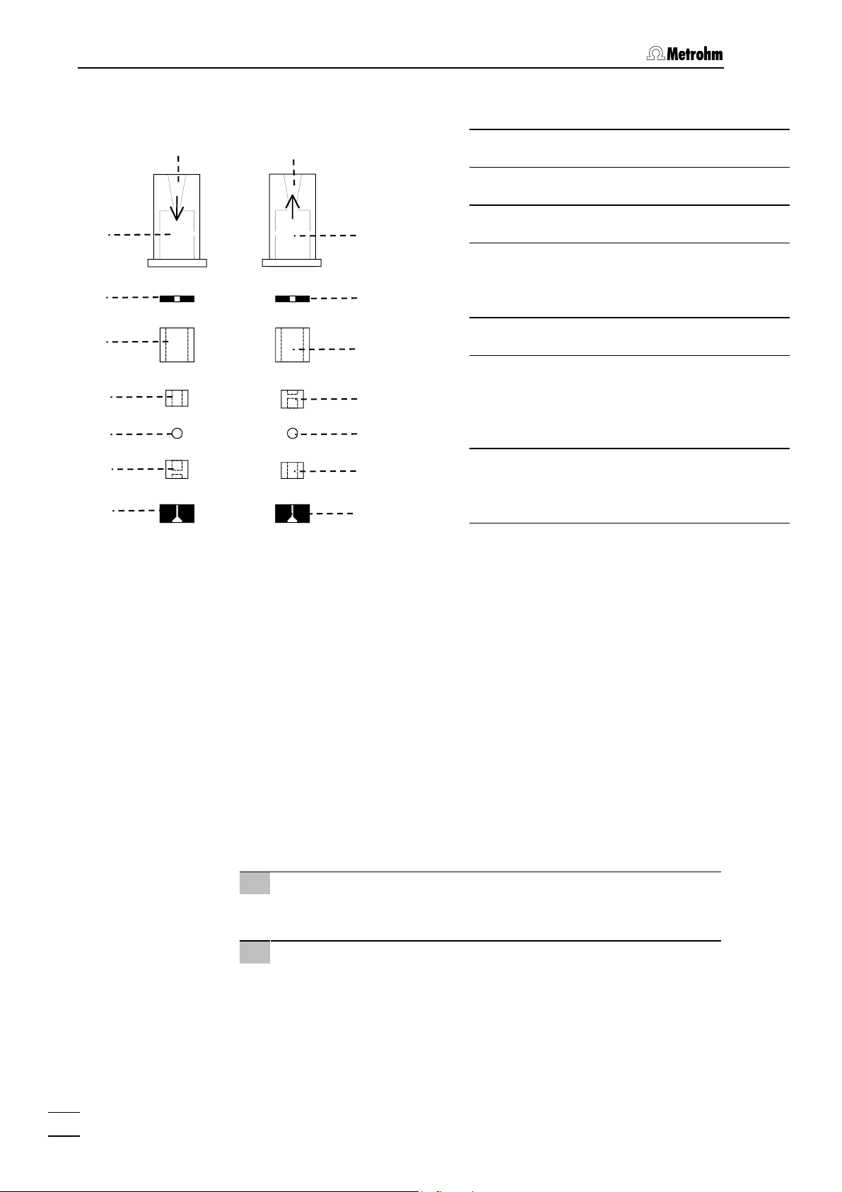
4 Notes - Maintenance - Faults
104
105
106
107
108
109
110
99
Inlet valve
100
Outlet valve
104
105
106
109
108
107
110
Valve housing
104
Sealing ring (black)
105
Sleeve
106
Sapphire sleeve
107
The bright side must point towards the
sapphire sphere.
Sapphire sphere
108
Ceramic holder for sapphire
109
sphere
The large recess must point in the direction of the sapphire sphere
Seal
110
The larger opening must point outwards
Figure 21: Components of inlet valve
99
and outlet valve
100
4.2.7 Regeneration of the suppressor module «MSM II»
Regenerating a suppressor operating at reduced
capacity
If the suppressor units are exposed to certain heavy metals (e.g. iron)
or organic contaminants for long periods of time, these can no longer
be completely removed by the regeneration solution normally used (50
mmol/L H
which, in milder cases, results in a reduced sensitivity to phosphates
and, in severe cases, in a strong increase in the baseline. If such capacity problems occur at one or several positions, the suppressor units
must be treated as follows:
1 Disconnect suppressor from IC system
• Disconnect suppressor from separating column and detector.
2 Regenerate suppressor
• Rinse each suppressor unit for about 15 min with one of the
). This diminishes the capacity of the suppressor units,
2SO4
following solutions:
Contamination with heavy metals
1 mol/L H
/ 0.1 mol/L oxalic acid
2SO4
Contamination with organic cationic complexing agents
76
861 Advanced Compact IC / Instructions for Use 8.861.1033
Page 87

4.2 Maintenance and servicing
0.1 mol/L H2SO4 / 0.1 mol/L oxalic acid / acetone 5%
Severe contamination with organic substances
0.2 mol/L H
/ acetone ≥ 20%
2SO4
The 6.1826.110 Pump tubing is made of PVC and must
not be used for rinsing with solutions which contain organic solvents. In such cases, rinse with different pump
tubing or a different pump.
3 Connect suppressor to IC system
• Reconnect suppressor to the IC system. If capacity problems
persist, replace the suppressor rotor (see Section 4.2.9).
4.2.8 Cleaning the suppressor
It may be necessary to clean the suppressor in the following cases:
• High counterpressure on the suppressor connection tubing
• Irremediable blockage of the suppressor (the suppressor can no
longer deliver solutions)
• Irremediable obstruction of the suppressor (the suppressor can
no longer be switched to next position)
To clean the connection piece and the rotor, proceed as follows (see
Figure 22):
1 Disconnect suppressor from IC system
• Disconnect input capillary 82 of the suppressor module «MSM
II» 46 from the separating column 73 (see Figure 16).
• Disconnect output capillary 83 from inlet capillary 44.
• Disconnect inlet capillaries 84 and 85 from the PEEK Cou-
pling 81 (supply from peristaltic pump).
2 Dismantle suppressor
• Unscrew nut 111 from suppressor holder 114.
• Pull out connection piece 112 and suppressor rotor 113 from
suppressor holder 114 (the connection piece and the rotor
normally stick together). If this is not the case, take a sharp
object, insert it in slot 115 of the suppressor holder and use it
to pull out suppressor rotor 113).
• Loosen connection piece 112 from suppressor rotor 113.
3 Clean input and output leads
• Connect each of the 6 capillary tubings attached to connec-
tion piece 112 to the high-pressure pump one after another,
and pump through ultrapure water.
• Check whether solution emerges from connection piece 112.
If one of the input or output leads remains blocked, replace
861 Advanced Compact IC / Instructions for Use 8.861.1033
77
Page 88

4 Notes - Maintenance - Faults
the connection piece 112 (order number 6.2832.010).
4 Clean suppressor rotor
• Clean the sealing surface of suppressor rotor 113 using a lint-
free cloth and ethanol.
5 Insert suppressor rotor
• Insert suppressor rotor 113 in suppressor holder 114 in such
a way that the tubing connections at the rear of the rotor fit in
the corresponding openings inside the rotor, and that one of
the three holes in the rotor can be seen from below in one of
the openings of the holder.
• If the rotor has been inserted correctly, its sealing surface will
be about 4 mm inside the holder. If this is not the case, bring
the rotor into the correct position from below with the aid of a
sharp object (e.g. a screwdriver).
Rotors which are not inserted correctly can be destroyed
when starting operation.
6 Clean connection piece
• Clean the sealing surface of connection piece 112 using a lint-
free cloth and ethanol.
7 Insert connection piece
• Insert connection piece 112 in suppressor holder 114 in such
a way that connection "1" is at the top, and that the three lugs
on the connection piece fit in the corresponding openings of
the holder.
• Screw nut 111 onto the thread of suppressor holder 114
manually (do not
111
112
use tools).
113
114
115
Figure 22: Assembling the suppressor
78
861 Advanced Compact IC / Instructions for Use 8.861.1033
Page 89

4.2 Maintenance and servicing
Screw nut
111
Connection piece (6.2832.010)
112
with input and output leads
Suppressor rotor (6.2832.000)
113
8 Connect and condition the suppressor
• Reconnect the suppressor to the IC system.
• Before switching the suppressor to the next position for the
first time, rinse all 3 suppressor units with solution for 5 min.
4.2.9 Replacing the suppressor
The suppressor in the suppressor block may have to be replaced in the
following cases:
• Irremediable loss of suppressor capacity (reduced phosphate
sensitivity and/or strong rise in baseline)
Suppressor holder
114
Slot in the suppressor holder
115
• Irremediable blockage of the suppressor (the suppressor can no
longer deliver solutions)
Both the 6.2832.000 Suppressor rotor and the 6.2832.010 Connection
piece with the input and output leads can be replaced. To replace these
components proceed as follows (see Figure 22):
1 Disconnect suppressor from IC system
• Disconnect all input and output leads of the suppressor from
IC system and peristaltic pump.
2 Dismantle suppressor
• Unscrew nut 111 from suppressor holder 114.
• Pull out connection piece 112 and suppressor rotor 113 from
suppressor holder 114 (the connection piece and the rotor
normally stick together). If this is not the case, take a sharp
object, insert it in slot 115 of the suppressor holder and use it
to pull out suppressor rotor 113).
• Loosen connection piece 112 from suppressor rotor 113.
3 Clean suppressor rotor
• Clean the sealing surface of new suppressor rotor 113
(6.2832.000) using a lint-free cloth and ethanol.
4 Insert suppressor rotor
• Insert new suppressor rotor 113 in suppressor holder 114 in
such a way that the tubing connections at the rear of the rotor
fit in the corresponding openings inside the rotor and that
one of the three holes in the rotor can be seen from below in
861 Advanced Compact IC / Instructions for Use 8.861.1033
79
Page 90

4 Notes - Maintenance - Faults
one of the openings of the holder.
• If the rotor has been inserted correctly, its sealing surface will
be about 4 mm inside the holder. If this is not the case, bring
the rotor into the correct position from below with the aid of a
sharp object (e.g. a screwdriver).
Rotors which are not inserted correctly can be destroyed
when starting operation.
5 Clean connection piece
• Clean the sealing surface of new connection piece 112
(6.2832.010) with the aid of a lint-free cloth and ethanol.
6 Insert connection piece
• Insert new connection piece 112 in suppressor holder 114 in
such a way that connection "1" is at the top and that the three
lugs on the connection piece fit in the corresponding openings of the holder.
• Screw nut 111 onto the thread of suppressor holder 114
manually (do not
use tools).
7 Connect and condition the suppressor
• Reconnect the suppressor to the IC system.
• Before switching the suppressor to the next position for the
first time, rinse all 3 suppressor units with solution for 5 min.
4.2.10 Replacing the pump tubing
The pump tubings used by the peristaltic pump are consumable material with a limited lifetime and should be exchanged at regular intervals
(approx. every 4 weeks under continuous use).
The working life of pump tubing depends to a considerable extent on
the contact pressure. This is why the contact pressure must be correctly set as described in Section 2.10.2. If the pump is to remain
switched off for a lengthy period of time the tubing cartridges 47 should
be raised completely by loosening the snap-action lever 50 on the righthand side (the set contact pressure remains unchanged).
As the pump is always operated on the same side the 6.1826.110
Pump tubings supplied can be used on both sides. To exchange a
pump tubing proceed as follows:
1 Remove old pump tubing
• Press contact pressure lever 48 on the tubing cartridge 47
down as far as it will go.
• Release tubing cartridge 47 from holding clamp 49 by press-
ing down snap-action lever 50 and remove from mounting pin
52 (see Figure 16).
• Remove old pump tubing 78 or 79.
2 Insert new pump tubing
80
861 Advanced Compact IC / Instructions for Use 8.861.1033
Page 91

4.2 Maintenance and servicing
• Insert the new pump tubing 78 or 79 in the tubing cartridge
47 as shown in Figure 15. The orange-yellow stopper 80
must click into the corresponding holder on the left-hand side
of the tubing cartridge.
• Place the tubing cartridge 47 on mounting pin 52 and press
down on the right-hand side until snap-action lever 50 clicks
into position on holding clamp 49. Take care that no kinks are
formed in the pump tubing.
3 Set contact pressure
• Switch on peristaltic pump.
• Press contact pressure lever 48 upwards until the solution
just starts to be drawn in. Then press contact pressure lever
upwards until it clicks once more to obtain optimal contact
pressure.
• Switch off peristaltic pump.
861 Advanced Compact IC / Instructions for Use 8.861.1033
81
Page 92

4 Notes - Maintenance - Faults
4.3 Faults and malfunctions
4.3.1 Error messages
If any type of malfunction occurs during operation of the 861 Advanced
Compact IC, this is shown by error messages in the PC program, which
appear either in an error window or in the
Follow the instructions listed in the Error window and close this window with
<OK>.
SYSTEM STATE window.
You will find further details of the error messages of the
window, their possible causes and the procedure for rectifying them in
the Software Instructions for Use «IC Net 2.3» Section 4.5.
4.3.2 Malfunctions and their rectification
If difficulties appear with The 861 Advanced Compact IC during analyses, their causes are best investigated in the order separating column
→ high-pressure pump → eluent → connections. Several of The
malfunctions which may appear are listed in the following table with details of possible causes and countermeasures.
Malfunction Cause Rectification
Baseline with high
noise level, pulsation
Drift of the
baseline
• Contaminated pump
valves
• Defective piston seals
• Thermal equilibrium not
yet reached
• Leak in system
• Evaporation of organic
solvent in eluent
SYSTEM STATE
• Clean the valves (see Sec-
tion 4.2.6)
• Replace the piston seals
(see Section 4.2.6)
• Condition system with
heating switched on
• Check connections and
make leakproof
• Ensure better closure of
eluent supply vessel
Considerable
pressure drop
Considerable
pressure rise
Chromatograms
with poor resolution, change in the
retention times
82
861 Advanced Compact IC / Instructions for Use 8.861.1033
• Leak in system • Check connections and
make leakproof
• Contamination of the fil-
ter in the 6.2821.120 Filter unit PEEK
• Blockage of the precol-
umn
• Change of column pack-
ing by injection of contaminated samples
• Deterioration in separa-
tion efficiency of the IC
column
• Replace the 6.2821.130
Filter (see Section 2.3.6)
• Change precolumn (see
Section 4.2.5)
• Regenerate column (see
Section 4.1.1) or replace
column (see Section 4.2.5)
:
Note
Samples should always
be microfiltered.
• Regenerate column (see
Section 4.1.1) or replace
column
Page 93

4.3 Faults and malfunctions
Malfunction Cause Rectification
Extreme peak
broadening,
splitting (double
peaks)
No feed of regeneration or
rinsing solution
for suppressor
• Dead volume at the co-
lumn ends
• Contact pressure too
low
• Leak in system
• Defective pump tubing
• Contamination of the fil-
ter in the 6.2821.120 Filter unit PEEK
• Counterpressure at sup-
pressor module «MSM
II» too high
• Check the connections
(use PEEK capillaries with
0.25 mm i.d. between injection valve and detector
block)
• Turn separation column (if
allowed), or replace it
• Adjust contact pressure
(see Section 2.10.2)
• Check connections and
make leakproof
• Replace pump tubing (see
Section 4.2.10)
• Replace the 6.2821.130
Filter (see Section 2.3.6)
• Clean or replace suppres-
sor (see Section
…
4.2.9)
4.2.7
861 Advanced Compact IC / Instructions for Use 8.861.1033
83
Page 94

4 Notes - Maintenance - Faults
4.4 Diagnostic tests / Validation / GLP
The requirements of GLP (Good Laboratory Practice) include a peri-
odic check of analytical measuring instruments with regard to their reproducibility and accuracy using Standard Operating Procedures,
SOP.
Under the title «Application Bulletin No. 277 – Validation of
Metrohm ion chromatographs» an example of such a standard operating procedure is available from Metrohm; it can be adapted and
used with the 861 Advanced Compact IC.
Further information on the subjects of QA, GLP and validation can also
be found in the brochure «Quality management with Metrohm»,
which is available from your local Metrohm agency.
Testing of the electronic and mechanical function groups of Metrohm
instruments can and should be performed as part of a regular service
by trained personnel of the manufacturing company (see Section 4.2.1).
All Metrohm instruments are equipped with start-up-test routines which
check for perfect functioning of the relevant assemblies when the instrument is switched on. If no error message is displayed, it may be assumed the instrument is operating without faults.
The Metrohm company also supplies its instruments with an integrated
diagnostic program which, in the case of possible malfunctions or faulty
behavior, allows the service technician to check the functioning of certain assemblies and localize the fault.
84
861 Advanced Compact IC / Instructions for Use 8.861.1033
Page 95

5.1 Technical data
5 Appendix
5.1 Technical data
Unless otherwise specified, the published data comprises typical values for the 861 Advanced Compact IC
at an ambient temperature of 25 °C.
5.1.1 Conductivity measurement
Measurement range 1 0…5000 µS/cm (resolution: 2.80 nS/cm)
Measurement range 2 0…1000 µS/cm (resolution: 0.56 nS/cm)
Measurement range 3 0…250 µS/cm (resolution: 0.14 nS/cm)
Measurement range 4 0…50 µS/cm (resolution: 0.028 nS/cm)
Maximum error ± 1 % of full scale value and
± 1 % of measurement value (k = 16.7/cm)
Linearity Deviations < ± 0.5 % of full scale value
Noise typ. 0.2 nS/cm (Total noise of the system -
Drift (electronic) typ. < 10 ppm/h of full scale value
Temperature dependence typ. < 40 ppm/°C of full scale value
Reserve range > 33 % (k = 16.7/cm)
Sampling rate 10 measurements/s (fixed)
5.1.2 Conductivity detector
Construction Thermostatted conductivity detector with
Measurement principle Alternating current measurement with 1 kHz fre-
Effective cell volume 0.8 µL
Cell constant approx. 17 /cm (the exact value is printed on the
chemical and electronical with separation column
and sequential suppression)
2 ring-shaped steel electrodes
quency and approx. 1.7 V amplitude (peak to
peak).
detector)
Maximum back pressure
for measuring cell
Thermostatting Connectable dynamic control to adjustable oper-
Operating temperature Adjustable in steps of 5°C from 25…45°C
861 Advanced Compact IC / Instructions for Use 8.861.1033
5.0 MPa (50 bar)
ating temperature
85
Page 96

5 Appendix
Max. temperature deviation ± 2.5°C
Heating time ≥ 30 min
Temperature stability ≤ 0.01°C at constant ambient temperature
Connection for detector
block
5.1.3 Injection valve
Actuator switching duration 100…150 ms
Pressure resistance 35 MPa (350 bar)
5.1.4 High-pressure pump
Type Serial dual piston pump with two valves
Pump capacity
Flow range 0.20...2.5 mL/min
Maximum error < ± 2 % of set value
Flow constancy < 0.5 % of set value
Reproducibility of eluent
flow
Pressure measurement
Pressure range at flow 0.2 ... 1.5 mL/min:
Dsub 15 pin (female)
typ. better than ± 0.1 %
0 ... 35.0 MPa (0 ... 350 bar)
at flow 1.5 ... 2.5 mL/min:
0 ... 25.0 MPa (0 ... 250 bar)
Residual pulsation < 10 % (at 1 mL/min water and 10 MPa pressure,
without pulsation dampener)
Measurement principle Piezoresistive measurement
Response time: 3 ms
Measurement volume: approx. 50 µL
Maximum error ± 3 % of set value
Resolution 0.1 MPa (conductivity measurements)
0.01 MPa (pressure measurements)
Sampling rate 1 measurement/piston stroke (pump running)
1 measurement/s (pump not running)
10 measurements/s (pressure measurements)
Safety shutdown
Function Automatic shutdown when upper and lower pres-
sure limits violated
Maximum pressure limit adjustable between 0.1...35.0 MPa (1...350 bar)
Response time: 1 pump cycle
86
861 Advanced Compact IC / Instructions for Use 8.861.1033
Page 97

5.1 Technical data
Minimum pressure limit adjustable between 0.1 ... 35.0 MPa (1...350 bar),
Pump head
Pump head volumes Main piston: 40 µL
Pump displacement
volumes
Length of stroke Main piston: 3.6 mm
inactive at 0 MPa
Response time: 5 pump cycles
Priming piston: 20 µL
Main piston: 28.5 µL
Priming piston: 14.25 µL
Priming piston: 1.8 mm
5.1.5 Peristaltic pump
Type 2-channel peristaltic pump
Pump capacity
Rotational speed 20 U/min at 50 Hz
24 U/min at 60 Hz
Flow range 0.4…0.5 mL/min with 6.1826.110 Pump tubing
Maximum error ± 5 %
Maximum pressure 0.4 MPa (4 bar)
Pumpable liquids Clear liquids with no solid contents
Pump tubing material PVC
5.1.6 Suppressor module «MSM II»
Switching duration 140 ms
Pressure resistance 2.5 MPa (25 bar)
5.1.7 Leak detector
Type Detector with 2 electrodes approx. 1 mm above
base of interior
Response level Resistance < 1 MΩ (for deion. water)
5.1.8 RS232 interface
Connector Dsub 9 pin (male)
Function TxD and RxD signal for connection with software
Default settings 9600 baud, 8 bit, 1 stop bit, no parity, XON/XOFF
861 Advanced Compact IC / Instructions for Use 8.861.1033
handshake
87
Page 98
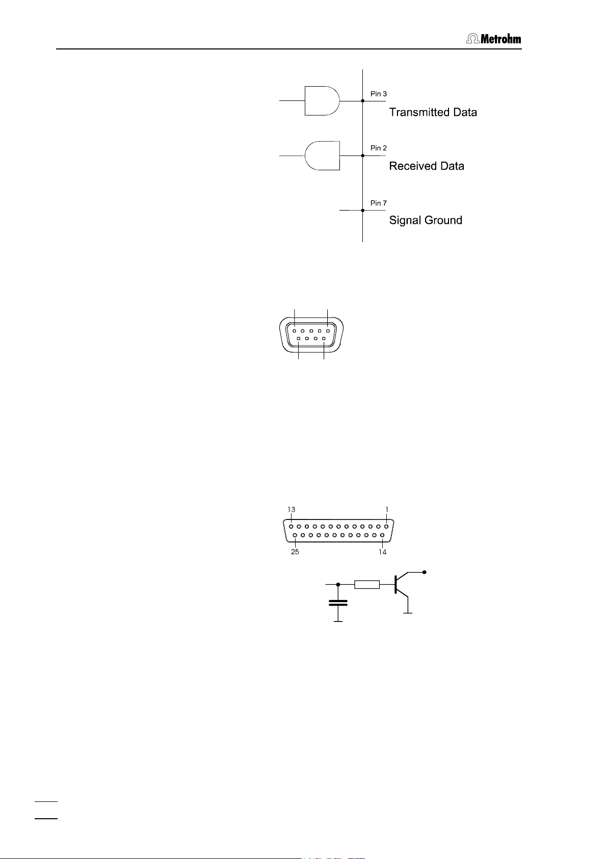
5 Appendix
Pin assignment
5.1.9 Analog output
Connector Dsub 9 pin (female)
5 1
Pin
1
6
5.1.10 Remote interface
Connector Dsub 25 pin (female)
Circuit diagram for
…
…
8
8
output lines 1
Assignment of
output lines 1
96
0 V
Signal 0...1 V
The other pins are not occupied.
Pin
Remote
Remote 1 Pin 18
Remote 2 Pin 4
Remote 3 Pin 3
Remote 4 Pin 1
Remote 5 Pin 2
Remote 6 Pin 16
Remote 7 Pin 17
Remote 8 Pin 5
88
861 Advanced Compact IC / Instructions for Use 8.861.1033
Page 99

5.1 Technical data
V+5V
Potentials
Pin 15
5.1.11 Mains connection
Voltage 115 V: 100...120 V ± 10 %
Frequency 50...60 Hz
Power consumption 100 VA
Fuse 5 mm dia., 20 mm length
5.1.12 Safety specifications
Construction/testing According to IEC 1010 / EN 61010 / UL 3101-1,
Safety directions The Instructions for Use include information and
0
230 V: 220...240 V ± 10 %
100…120 V: 0.63 A (slow-blow)
220…240 V: 0.315 A (slow-blow)
protection class 1, degree of protection IP20
warnings which must be heeded by the user to
assure safe operation of the instrument.
Pin 14
Pin 25
5.1.13 Electromagnetic compatibility (EMC)
Emitted interference Standards met:
-IEC/EN 61326
-EN 55022
-CISPR 22
-IEC/EN 61000-3-2
Immunity to interference Standards met:
- EN/IEC 61326
- EN/IEC 61000-4-2
- EN/IEC 61000-4-3
- EN/IEC 61000-4-4
- EN/IEC 61000-4-5
- EN/IEC 61000-4-6
- EN/IEC 61000-4-8
- EN/IEC 61000-4-11
- EN/IEC 61000-4-14
- Namur
5.1.14 Ambient temperature
Nominal operating range +5…+45°C
(at 20…80 % atmospheric humidity)
Storage –20…+70°C
Transport –40…+70°C
861 Advanced Compact IC / Instructions for Use 8.861.1033
89
Page 100

5 Appendix
5.1.15 Housing
Material of cover Polyurethane rigid foam (PUR) with fire protection
for fire class UL94VO, CFC-free
Material of base Steel, enameled
Width 259 mm
Height 446 mm
Depth 355 mm
Weight
2.861.0010
2.861.0020
13.5 kg (without accessories)
15.7 kg (with accessories)
14.7 kg (without accessories)
21.7 kg (with accessories)
90
861 Advanced Compact IC / Instructions for Use 8.861.1033
 Loading...